EP2365600A2 - Verfahren, computerlesbares Medium und System für Lastmanagement - Google Patents
Verfahren, computerlesbares Medium und System für Lastmanagement Download PDFInfo
- Publication number
- EP2365600A2 EP2365600A2 EP11153296A EP11153296A EP2365600A2 EP 2365600 A2 EP2365600 A2 EP 2365600A2 EP 11153296 A EP11153296 A EP 11153296A EP 11153296 A EP11153296 A EP 11153296A EP 2365600 A2 EP2365600 A2 EP 2365600A2
- Authority
- EP
- European Patent Office
- Prior art keywords
- power
- load
- time point
- rate interval
- electricity demand
- Prior art date
- Legal status (The legal status is an assumption and is not a legal conclusion. Google has not performed a legal analysis and makes no representation as to the accuracy of the status listed.)
- Ceased
Links
Images



Classifications
-
- H—ELECTRICITY
- H02—GENERATION; CONVERSION OR DISTRIBUTION OF ELECTRIC POWER
- H02J—ELECTRIC POWER NETWORKS; CIRCUIT ARRANGEMENTS OR SYSTEMS FOR SUPPLYING OR DISTRIBUTING ELECTRIC POWER; SYSTEMS FOR STORING ELECTRIC ENERGY
- H02J3/00—Circuit arrangements for AC mains or AC distribution networks
- H02J3/17—Demand-responsive operation of AC power transmission or distribution networks
-
- H—ELECTRICITY
- H02—GENERATION; CONVERSION OR DISTRIBUTION OF ELECTRIC POWER
- H02J—ELECTRIC POWER NETWORKS; CIRCUIT ARRANGEMENTS OR SYSTEMS FOR SUPPLYING OR DISTRIBUTING ELECTRIC POWER; SYSTEMS FOR STORING ELECTRIC ENERGY
- H02J3/00—Circuit arrangements for AC mains or AC distribution networks
- H02J3/12—Arrangements for adjusting voltage in AC networks by changing a characteristic of the network load
- H02J3/14—Arrangements for adjusting voltage in AC networks by changing a characteristic of the network load by switching loads on to, or off from, the networks, e.g. progressively balanced loading
-
- G—PHYSICS
- G06—COMPUTING OR CALCULATING; COUNTING
- G06Q—INFORMATION AND COMMUNICATION TECHNOLOGY [ICT] SPECIALLY ADAPTED FOR ADMINISTRATIVE, COMMERCIAL, FINANCIAL, MANAGERIAL OR SUPERVISORY PURPOSES; SYSTEMS OR METHODS SPECIALLY ADAPTED FOR ADMINISTRATIVE, COMMERCIAL, FINANCIAL, MANAGERIAL OR SUPERVISORY PURPOSES, NOT OTHERWISE PROVIDED FOR
- G06Q50/00—Information and communication technology [ICT] specially adapted for implementation of business processes of specific business sectors, e.g. utilities or tourism
- G06Q50/06—Energy or water supply
-
- H—ELECTRICITY
- H02—GENERATION; CONVERSION OR DISTRIBUTION OF ELECTRIC POWER
- H02J—ELECTRIC POWER NETWORKS; CIRCUIT ARRANGEMENTS OR SYSTEMS FOR SUPPLYING OR DISTRIBUTING ELECTRIC POWER; SYSTEMS FOR STORING ELECTRIC ENERGY
- H02J2105/00—Networks for supplying or distributing electric power characterised by their spatial reach or by the load
- H02J2105/40—Networks for supplying or distributing electric power characterised by their spatial reach or by the load characterised by the loads connecting to the networks or being supplied by the networks
- H02J2105/42—Home appliances
-
- Y—GENERAL TAGGING OF NEW TECHNOLOGICAL DEVELOPMENTS; GENERAL TAGGING OF CROSS-SECTIONAL TECHNOLOGIES SPANNING OVER SEVERAL SECTIONS OF THE IPC; TECHNICAL SUBJECTS COVERED BY FORMER USPC CROSS-REFERENCE ART COLLECTIONS [XRACs] AND DIGESTS
- Y02—TECHNOLOGIES OR APPLICATIONS FOR MITIGATION OR ADAPTATION AGAINST CLIMATE CHANGE
- Y02B—CLIMATE CHANGE MITIGATION TECHNOLOGIES RELATED TO BUILDINGS, e.g. HOUSING, HOUSE APPLIANCES OR RELATED END-USER APPLICATIONS
- Y02B70/00—Technologies for an efficient end-user side electric power management and consumption
- Y02B70/30—Systems integrating technologies related to power network operation and communication or information technologies for improving the carbon footprint of the management of residential or tertiary loads, i.e. smart grids as climate change mitigation technology in the buildings sector, including also the last stages of power distribution and the control, monitoring or operating management systems at local level
-
- Y—GENERAL TAGGING OF NEW TECHNOLOGICAL DEVELOPMENTS; GENERAL TAGGING OF CROSS-SECTIONAL TECHNOLOGIES SPANNING OVER SEVERAL SECTIONS OF THE IPC; TECHNICAL SUBJECTS COVERED BY FORMER USPC CROSS-REFERENCE ART COLLECTIONS [XRACs] AND DIGESTS
- Y02—TECHNOLOGIES OR APPLICATIONS FOR MITIGATION OR ADAPTATION AGAINST CLIMATE CHANGE
- Y02B—CLIMATE CHANGE MITIGATION TECHNOLOGIES RELATED TO BUILDINGS, e.g. HOUSING, HOUSE APPLIANCES OR RELATED END-USER APPLICATIONS
- Y02B70/00—Technologies for an efficient end-user side electric power management and consumption
- Y02B70/30—Systems integrating technologies related to power network operation and communication or information technologies for improving the carbon footprint of the management of residential or tertiary loads, i.e. smart grids as climate change mitigation technology in the buildings sector, including also the last stages of power distribution and the control, monitoring or operating management systems at local level
- Y02B70/3225—Demand response systems, e.g. load shedding, peak shaving
-
- Y—GENERAL TAGGING OF NEW TECHNOLOGICAL DEVELOPMENTS; GENERAL TAGGING OF CROSS-SECTIONAL TECHNOLOGIES SPANNING OVER SEVERAL SECTIONS OF THE IPC; TECHNICAL SUBJECTS COVERED BY FORMER USPC CROSS-REFERENCE ART COLLECTIONS [XRACs] AND DIGESTS
- Y04—INFORMATION OR COMMUNICATION TECHNOLOGIES HAVING AN IMPACT ON OTHER TECHNOLOGY AREAS
- Y04S—SYSTEMS INTEGRATING TECHNOLOGIES RELATED TO POWER NETWORK OPERATION, COMMUNICATION OR INFORMATION TECHNOLOGIES FOR IMPROVING THE ELECTRICAL POWER GENERATION, TRANSMISSION, DISTRIBUTION, MANAGEMENT OR USAGE, i.e. SMART GRIDS
- Y04S20/00—Management or operation of end-user stationary applications or the last stages of power distribution; Controlling, monitoring or operating thereof
- Y04S20/20—End-user application control systems
- Y04S20/222—Demand response systems, e.g. load shedding, peak shaving
-
- Y—GENERAL TAGGING OF NEW TECHNOLOGICAL DEVELOPMENTS; GENERAL TAGGING OF CROSS-SECTIONAL TECHNOLOGIES SPANNING OVER SEVERAL SECTIONS OF THE IPC; TECHNICAL SUBJECTS COVERED BY FORMER USPC CROSS-REFERENCE ART COLLECTIONS [XRACs] AND DIGESTS
- Y04—INFORMATION OR COMMUNICATION TECHNOLOGIES HAVING AN IMPACT ON OTHER TECHNOLOGY AREAS
- Y04S—SYSTEMS INTEGRATING TECHNOLOGIES RELATED TO POWER NETWORK OPERATION, COMMUNICATION OR INFORMATION TECHNOLOGIES FOR IMPROVING THE ELECTRICAL POWER GENERATION, TRANSMISSION, DISTRIBUTION, MANAGEMENT OR USAGE, i.e. SMART GRIDS
- Y04S20/00—Management or operation of end-user stationary applications or the last stages of power distribution; Controlling, monitoring or operating thereof
- Y04S20/20—End-user application control systems
- Y04S20/242—Home appliances
Definitions
- Example embodiments relate to a demand response method, a computer-readable medium and system reducing peak power rates when power rates are high to reduce electricity bills.
- demand management is a focus of attention, and a number of studies are underway into demand response (DR) about the developed demand management formats.
- the demand response (DR) can be defined as a variation of consumption format depending on variation in power rates.
- the demand response (DR) may be defined as incentive payment to restrict the use of electricity when power rates are high.
- the demand response (DR) may further include an intentional procedure for changing a consumption behavior in the same manner as in the aforementioned incentive payment.
- the demand response (DR) of consumers may be derived. Consumers can reduce the amount of power consumption during a specific time interval of high or expensive power rates even if they experience inconvenience during the specific time interval. For example, the consumer may temporarily stop an air-conditioner in midsummer to reduce the power consumption when power rates are high.
- a conventional DR system has proposed an easy and simple control scheme dependent upon cost or price information. That is, the conventional DR system has been designed to limit the operation of household appliances in response to power rates, which may cause user inconvenience.
- a demand response method including receiving, by a processor, electricity demand information, extracting, by the processor, an electricity demand pattern in response to the received electricity demand information, dividing, by the processor, a unit interval into a high-power-rate interval and a low-power-rate interval in response to the extracted electricity demand pattern, estimating, by the processor, an estimated operation start time point of a load, and changing, by the processor,, if the estimated operation time point is in the high-power-rate interval, an operation start time point of the load to any time of the low-power-rate interval to operate the load operation in the low-power-rate interval.
- the load may be a high-power-consumption load.
- the load may be any one of a defrosting heater of a refrigerator, a defrosting heater of an air-conditioner, or a heater of a washing machine.
- the changing of the operation time of the load to any time of the low-power-rate interval may include determining, if the estimated operation time point is in the high-power-rate interval, whether a limit delay time point at which the load operation is maximally delayed is contained in the high-power-rate interval, and performing a pre-operation for moving the operation time point of the load forward or a post-operation for moving the operation time point of the load backward according to the determined result to allow the operation time point of the load to move from the high-power-rate interval.
- the performing of the pre-operation or the post-operation may include, if a limit delay time point of the load is contained in the high-power-rate interval, shifting the operation time point of the load to the low-power-rate interval located before the high-power-rate interval, and if the limit delay time point of the load is not contained in the high-power-rate interval, delaying the operation time point of the load toward a low-power-rate interval located after the high-power-rate interval.
- a demand response method including receiving, by a processor, electricity demand information, extracting, by the processor, an electricity demand pattern in response to the received electricity demand information, dividing, by the processor, a unit interval into a high-power-rate interval and a low-power-rate interval in response to the extracted electricity demand pattern, and performing, by the processor, at least one of a pre-cooling operation wherein a household appliance starts a cooling operation in a low-power-rate interval before the high-power-rate interval, or a post-cooling operation wherein a start time of a final-cycle cooling operation performed in the high-power-rate interval is delayed to a low-power-rate interval located after the high-power-rate interval.
- the pre-cooling operation may be compulsorily cooled to a specific temperature lower than a predetermined temperature of a previous-cycle cooling operation.
- a demand response system including a receiving unit to receive electricity demand information, an electricity demand recording unit to record information on electricity demand amount in response to the received electricity demand information, an electricity demand pattern extracting unit to extract an electricity demand pattern from the electricity demand amount recorded in the electricity demand recording unit, and a demand response (DR) controller to compare an electricity demand amount of an electricity demand pattern extracted from the electricity demand pattern extracting unit with a predetermined electricity demand amount, divide a unit interval into a high-power-rate interval and a low-power-rate interval, estimate an estimated operation time point of a load, and shift a start time point of the load operation to the low-power-rate interval when the estimated operation time point is in the high-power-rate interval to start the load operation in the low-power-rate interval.
- DR demand response
- the load may be any one of a defrosting heater of a refrigerator, a defrosting heater of an air-conditioner, or a heater of a washing machine.
- the DR controller may determine, if the estimated operation time point falls within the high-power-rate interval, whether a limit delay time point at which the load operation is maximally delayed falls within the high-power-rate interval, move the operation time point of the load toward the low-power-rate interval located before the high-power-rate interval when the limit delay time point of the load falls within the high-power-rate interval, and delay the operation time point of the load toward a low-power-rate interval located after the high-power-rate interval when the limit delay time point of the load does not fall within the high-power-rate interval.
- a demand response method including receiving, by a processor, power rate information, establishing, by the processor, a plurality of demand response (DR) levels having different power rates and different allowed amounts of power in response to the power rate information, recognizing, by the processor, a current DR level, measuring, by the processor, an amount of power consumed by a household appliance, comparing, by the processor, the measured power amount with an allowed power amount corresponding to the recognized DR level, and delaying, by the processor, if the current power amount is equal to or greater than the allowed power amount corresponding to the current DR level, a load operation to an interval of a DR level lower than a current DR level until the power amount reaches the allowed power amount corresponding to the current DR level.
- DR demand response
- the establishing of the plurality of DR levels may include establishing a plurality of DR levels having different power rates and different allowed power amounts on a basis of a minimum power rate and a maximum power rate of the received power rate information.
- the load may include a plurality of loads having different priorities, and operation time points of individual loads may be sequentially delayed in ascending numerical order of priorities toward a low-DR-level interval having a DR level lower than the current DR level.
- a demand response system including a receiving unit to receive power rate information, a demand response (DR) level setup unit to establish a plurality of DR levels having different power rates and different allowed power amounts in response to the received power rate information, and a DR controller to recognize a current DR level, measure an amount of power consumed by a household appliance, compare the measured power amount with an allowed power amount corresponding to the recognized DR level, delay, when the power amount is equal to or higher than the allowed power amount corresponding to the current DR level, a load operation toward an interval of a DR level lower than a current DR level until the power amount reaches the allowed power amount corresponding to the current DR level.
- DR demand response
- the load may include a plurality of loads having different priorities, and the DR controller may delay an operation time point of each load in ascending numerical order of priorities toward a low-DR-level interval having a DR level lower than the current DR level.
- a demand response method including receiving, by a processor, power rate information, establishing, by the processor, a plurality of demand response (DR) levels having different power rates in response to the received power rate information, recognizing, by the processor, a current DR level, determining, by the processor, whether the current DR level is equal to or higher than a predetermined DR level, and delaying, by the processor, if the current DR level is equal to or higher than the predetermined DR level, a start time point of a load to be performed in the current-DR-level interval toward a low-DR-level interval having a low DR level.
- DR demand response
- a demand response system including a receiving unit to receive power rate information, a demand response (DR) level setup unit to establish a plurality of DR levels having different power rates in response to the received power rate information, and a DR controller to recognize a current DR level, determine whether the current DR level is equal to or higher than a predetermined DR level, and delay, if the current DR level is equal to or higher than the predetermined DR level, a start time point of a load to be performed in the current-DR-level interval to a low-DR-level interval having a low DR level.
- DR demand response
- a method including interpreting, by a processor, electricity demand information to generate an electricity demand pattern, determining, by the processor, demand rate levels to generate a high power rate time period and a low power rate time period by using the electricity demand pattern and modifying, by the processor, an electrical appliance operation time forward or backward in time to the low power rate time period if the electrical appliance operation time is preset in the high power rate time period, where the modifying is dependent upon at least one of a maximum delay time, a priority of an electrical appliance and an influence on quality.
- At least one non-transitory computer readable medium including computer readable instructions that control at least one processor to implement methods of one or more embodiments.
- FIG. 1 is a configuration diagram illustrating a demand response (DR) system according to example embodiments.
- the DR system may include a smartmeter 10 installed in a home to transmit and receive information to and from a power company; a DR control unit 20 to receive information about electric demand or electric charges from the smartmeter 10; and respective household appliances 30, 40 and 50 connected to the DR control unit 20 over a network.
- Each household appliance 30, 40 or 50 may perform a desired function using power received through a power line.
- the amount of power consumed by each household appliance 30, 40 or 50 may be measured by a wattmeter 31, 41 or 51 installed in the household appliance 30, 40 or 50. Each wattmeter 31, 41 or 51 may measure the actual power consumption of the household appliance 30, 40 or 50. Each wattmeter 30, 40 or 50 may be properly controlled by power information, and information about the amount of power used by a current household appliance may be transmitted to the DR control unit 20.
- the household appliance 30, 40 or 50 may include all kinds of electric household appliances, for example, a refrigerator, an air-conditioner, a washing machine, a television, an official machine, etc.
- the DR controller 50 may receive information about electricity demand or electric charges, etc, determine a DR level according to the received information, and transmit the determined DR level to each of the household appliances 30, 40 and 50.
- the DR control unit 20 may record electricity demand information received from the power company through the smartmeter 10 at intervals of a predetermined time (i.e., every unit time), and extract an electricity demand pattern using an average electricity demand for each time zone during a predetermined period.
- the DR control unit 20 may classify a time interval depending on the electricity demand pattern into a high-power-rate assessment interval and a low-power-rate assessment interval on the basis of a predetermined electricity demand amount.
- FIG. 2 is a control block diagram illustrating a DR control unit for use in a DR system according to example embodiments.
- the DR control unit 20 may include a DR controller 28, an input unit 21, a receiving unit 22, an electricity demand recording unit 23, an electricity demand pattern extracting unit 24, a transmitting unit 25, a display unit 26 and a storage unit 27.
- the input unit 21, may be for example, a keypad, a keyboard, a joystick, a touchpad, a button, etc., and may be used as an interface unit allowing a user to enter a desired command.
- the input unit 21 may be integrated with the display unit 26, and may be a touchscreen.
- the receiving unit 22 may receive electricity demand information from the smartmeter 10, and receive various kinds of information from each household appliance 30, 40 or 50.
- the electricity demand recording unit 23 may record information about the electricity demand amount received from the smartmeter 10 at intervals of a predetermined unit time.
- the electricity demand recording unit 23 may record information about the accumulated electricity demand amount used during the unit time. For example, assuming that the unit time is set to one hour, the electricity demand amount may be measured and recorded 24 times each day.
- the electricity demand pattern extracting unit 24 may extract the electricity demand pattern from the electricity demand amount recorded in the electricity demand recording unit 23.
- the electricity demand pattern extracting unit 24 may calculate the electricity demand amount at intervals of a predetermined time (e.g., every second) and the electricity demand pattern extracting unit 24 may make out the electricity demand pattern.
- the electricity demand pattern may be denoted by an electricity demand amount varying with the lapse of a unit time within a pattern period.
- the pattern period may be set to any of one day, one week, one month, one year, etc.
- the unit time may be set to one hour and a pattern period may be set to one day.
- An average of all the daily electricity demand amounts may be calculated for each unit time of the pattern period, and the electricity demand pattern may be obtained.
- the electricity demand amount data measured between midnight and 1 o'clock (1AM) for each day may be averaged to obtain the electricity demand amount of the 1 o'clock (1AM), the electricity demand amount data measured to 1 (1AM) or 2 o'clock (2AM) for each day is averaged to obtain the electricity demand amount of the 2 o'clock.
- the electricity demand pattern extracting unit 24 may calculate the average electricity demand amount for each unit time of the pattern period.
- the graph shown in FIG. 3 may show the electricity demand pattern.
- the electric demand pattern may be indicated by either the power rates in response to the lapse of a unit time or may also be denoted by different DR levels having different power rates.
- the transmitting unit 35 may transmit various kinds of information to the individual household appliances 30, 40 and 50.
- the display unit 26 may visually indicate operations of the DR control unit 20, or may display cost or rate information varying with the electricity demand pattern.
- the storage unit 27 may store the electricity demand pattern extracted from the electricity demand pattern extracting unit 24, as well as various kinds of information.
- the DR controller 28 may control individual elements of the DR control unit 20.
- the DR controller 28 may receive information about the daily electricity demand amount from the smartmeter 10, and record the received information in the electricity demand recording unit 23.
- the DR controller 28 may calculate an average for each time interval during the predetermined time interval in association with a daily electricity demand amount recorded in the electricity demand recording unit 23 using the electricity demand pattern extracting unit 24, to allow the electricity demand pattern extracting unit 24 to extract the electricity demand pattern.
- the DR controller 28 may apply a predetermined electricity demand amount for identifying each time interval to the extracted electricity demand pattern, to allow the DR controller 28 to classify a time interval in response to the electricity demand pattern into a high-power-rate assessment interval and a low-power-rate assessment interval.
- the DR controller 28 may determine a time interval in which the electricity demand amount of the electricity demand pattern is equal to or higher than a predetermined electricity demand amount to be a high-power-rate assessment interval, and determine another time interval in which the electricity demand amount of the electricity demand pattern is less than the predetermined electricity demand amount to be a low-power-rate assessment interval.
- the DR controller 28 may predict an estimated operation time point of a high-power-consumption load. If the estimated operation time point of the high-power-consumption load falls within the low-power-rate assessment interval, the DR controller 28 may start operating the load at the estimated operation time point.
- the DR controller 28 may move the operation time point of the high-power-consumption load toward a low-power-rate assessment interval located before a high-power-rate assessment interval, and the high-power-consumption load may be pre-operated. Otherwise, the DR controller 28 may move the operation time point of the high-power-consumption load toward a low-power-rate assessment interval located behind the high-power-rate assessment interval, and the high-power-consumption load may be post-operated.
- the DR controller 28 may move the load toward the low-power-rate assessment interval located just before the high-power-rate assessment interval, to perform the pre-operation of the load.
- the DR controller 28 may move the load toward the low-power-rate assessment interval located just after the high-power-rate assessment interval, to perform the post-operation of the load.
- FIG. 4 is a flowchart illustrating a load control method for use in a household appliance using an electricity demand pattern in a DR system according to example embodiments.
- the DR controller 28 may control the receiving unit 22 to receive information about a daily electricity demand amount from the smartmeter 10 at operation 100.
- the DR controller 28 may record the received electricity demand amount information in the electricity demand recording unit 23 at operation 101.
- the DR controller 28 may control the electricity demand pattern extracting unit 24 to calculate an average for each time interval during a predetermined time period in association with a daily electricity demand amount recorded in the electricity demand recording unit 23 at operation 102.
- the DR controller 28 may apply a predetermined electricity demand amount for each time interval classification to the extracted electricity demand pattern, and divide a time interval in response to the electricity demand pattern into a plurality of time zones having different rates at operation 103. In this case, the DR controller 28 may determine one time interval in which the electricity demand amount of the electricity demand pattern is equal to or higher than a predetermined electricity demand amount to be a high-power-rate assessment interval, and determine another time interval in which the electricity demand amount of the electricity demand pattern is less than the predetermined electricity demand amount to be a low-power-rate assessment interval.
- the time interval depending on the electricity demand pattern may be classified into a plurality of time intervals having different rates by the DR controller 28. Then, the DR controller 28 may communicate with the household appliance, and estimate an estimated operation time point of a high-power-consumption load from among loads of the household appliance at operation 104.
- the DR controller 28 may determine whether the estimated operation time point falls within the high-power-rate assessment interval at operation 105.
- the DR controller 28 may control the transmitting unit 25 to transmit a control command to a household appliance, wherein the control command may enable the load to operate at a predetermined time point (i.e., a low-power-rate assessment interval), and the load can be normally operated at operation 107. Therefore, the load may be operated at an original operation time point.
- a predetermined time point i.e., a low-power-rate assessment interval
- the DR controller 28 may determine whether a predetermined limit delay time point at which the load operation can be maximally delayed may be contained in the high-power-rate assessment interval at operation 106.
- the DR controller 28 may control the transmitting unit 25 to transmit a control command to the household appliance, wherein the control command may allow the beginning and completion of the load operation to be carried out in the low-power-rate assessment interval preceding the high-power-rate assessment interval, and the pre-operation of the load may be performed at operation 108. That is, the DR controller 28 may move the beginning point of the load operation toward the low-power-rate assessment interval located before the high-power-rate assessment interval, to perform the pre-operation of the load.
- the DR controller may transmit a control command to the household appliance through the transmitting unit 25 in such a manner that the load operation may be carried out when the high-power-rate assessment interval is changed to the low-power-rate assessment interval, to perform the post-operation of the load at operation 109.
- the DR controller may 28 control the beginning point of the load operation to be delayed toward the low-power-rate assessment interval located after the high-power-rate assessment interval, to post-operate the load at operation 109.
- the limit delay time point may be pre-determined in consideration of the load operation time.
- a refrigerator or air-conditioner may prevent the defrosting heater operation, which consumes a great deal of power or energy, from being operated in a high-power-rate interval, such that only the low-power-consumption load can be operated in the high-power-rate interval, thereby minimizing power consumption.
- the cooling operation conducted via a compressor of the refrigerator or air-conditioner may be pre-operated before a current time enters a high-power-rate interval, and temperature of the room air may be pre-decreased.
- the hot-water supplying operation conducted via a heater of a washing machine may be pre-operated before a current time enters the high-power-rate interval, and water may be pre-heated, such that only the low-power-consumption load may be operated in the high-power-rate interval, thereby minimizing power consumption.
- the DR controller may greatly reduce power consumption of the household appliance during a high-power-rate interval, and the power rates or energy costs may be greatly reduced and the limitation in operating the household appliance can be minimized, resulting in considerable reduction in user inconvenience.
- FIG. 5 is a graph illustrating a defrosting control method for a refrigerator using an electricity demand pattern in a DR system according to example embodiments.
- the frost may be formed at an evaporator during the cooling operation of the refrigerator, and it may be necessary for the refrigerator to periodically perform the defrosting operation.
- the defrosting operation may be carried out by a heater installed in the refrigerator, and a large amount of power or energy may be consumed during the defrosting operation.
- the defrosting operation is carried out in the remaining intervals other than the high-power-rate interval using the electricity demand pattern, the power rates or energy costs may be greatly reduced.
- the time interval depending on the electricity demand pattern may be classified into a high-power-rate assessment interval and a low-power-rate assessment interval according to a predetermined demand level decision line.
- the DR controller 28 may estimate the start point of the operation of the high-power-consumption load by communicating with the corresponding household appliance.
- the DR controller 28 may start operating the load at the time point "a1"
- the operation time point of the load falls within the high-power-rate assessment interval as denoted by a time point "b1" and the high-power-rate assessment interval is kept to a time point "b2", beyond which the load operation cannot be delayed, the operation time point of the load is shifted to a time point "b3" within the low-power-rate assessment interval located before the high-power-rate assessment interval, and the load pre-operation is performed.
- the operation time point of the load may be delayed to a time point "c3" contained in the low-power-rate assessment interval located after the high-power-rate assessment interval, and the load is post-operated.
- FIG. 6 is a graph illustrating a pre-cooling control method for a refrigerator using an electricity demand pattern in a DR system according to example embodiments.
- the DR system may pre-control the cooling operation at a low temperature prior to the increasing of the electricity demand, and then maintain the stationary status when the electricity demand is high.
- the DR system may prevent a first cooling operation from being performed in the high-power-rate assessment interval.
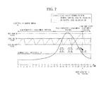
- FIG. 7 is a graph illustrating a post-cooling control method for a refrigerator using an electricity demand pattern in a DR system according to example embodiments.
- the DR system may delay the cooling operation of one cycle prior to the decreasing of the electricity demand using the electricity demand pattern, and perform the cooling operation when the electricity demand is decreased.
- the increased inner temperature may affect the quality, and a maximum ON temperature may be established.
- the cooling operation may be immediately performed.
- the DR system may prevent the last cooling operation from being performed in the high-power-rate assessment interval.
- the electricity demand pattern stored in the DR controller 20 may be pre-stored in each household appliance 30, 40 or 50.
- each household appliance 30, 40 or 50 may perform the load delay operation on the basis of the electricity demand pattern stored in each household appliance 30, 40 or 50.
- FIG.8 is a control block diagram illustrating a DR controller for use in a DR system according to example embodiments.
- the DR controller 20 of the DR system may include an input unit 21, a receiving unit 22, a DR level setup unit 60, a load measuring unit 61, a transmitting unit 25, a display unit 26, and a storage unit 27.
- the input unit 21 may be used as an interface unit to allow a user to enter a desired command, and may be for example, a keypad, a keyboard, a joystick, a touchpad, a button, etc.
- the receiving unit 22 may receive power rate information from the smartmeter 10, and receive various kinds of information from each household appliance 30, 40 or 50 installed in a home.
- the DR level setup unit 60 may establish a plurality of DR levels having different amounts of power on the basis of power rate information received from the smartmeter 10. For example, the DR level setup unit 60 may establish four DR levels having different power rates and different amounts of power on the basis of a minimum power rate and a maximum power rate.
- the load measuring unit 61 may measure the amount of power consumed in each household appliance installed in a home at intervals of a predetermined time.
- the transmitting unit 35 may transmit various kinds of information to the individual household appliances 30, 40 and 50.
- the display unit 26 may visually indicate operations of the DR control unit 20, or may display a DR level in response to the power rate.
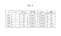
- the storage unit 27 may store DR level information or various kinds of information associated with the DR control unit 20. In addition, the storage unit 27 may store priority, quality influence, maximum delay time, delay standby time, and power consumption of respective loads of a household appliance (See FIG. 9 ).
- the DR controller 28 may receive power rate information from the smartmeter 10 through the receiving unit 22, and establish a plurality of DR levels having different amounts of power and different allowed amounts of power on the basis of a minimum power rate and a maximum power rate of the power rate information through the DR level setup unit 60.
- the DR controller 28 may recognize a current DR level form among DR levels established by the DR level setup unit 60, and measure a current amount of power consumed by the household appliance through the load measuring unit 61.
- the DR controller 28 may compare a current measured amount of power with an allowed amount of power corresponding to the current DR level. If the measured amount of power is equal to or higher than the allowed amount of power corresponding to the current DR level, the DR controller 28 may delay the operation of respective loads in descending numerical order of priorities until a current amount of power reaches an allowed amount of power corresponding to the current DR level. If the current amount of power is less than the allowed amount of power corresponding to the current DR level, the DR controller 28 may normally operate the respective loads in predetermined operation orders.
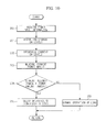
- FIG. 10 is a flowchart illustrating a method of delaying the operation of each load in such a manner that a DR system controls the amount of power used by a household appliance within an allowed amount of power in response to a current DR level according to example embodiments.
- the DR controller 28 may receive power rate information from the smartmeter 10 through the receiving unit 22 at operation 200.
- the DR controller 28 may establish a plurality of DR levels through the DR level setup unit 60 at operation 201.
- the DR level may have four levels (i.e., first to fourth DR levels), and have different power rates and different allowed amounts of power.
- the power rate to be assessed may be gradually increased and established.
- the DR controller 28 may recognize a current DR level of the household appliance at operation 202.
- the DR controller 28 may measure a current amount of power per unit time of the household appliance through the load measuring unit 61 at operation 203.
- the DR controller 28 may compare the measured amount of power with the allowed amount of power corresponding to the current DR level, and determine whether the current measured amount of power is equal to or higher than the allowed amount of power corresponding to the current DR level at operation 204.
- the DR controller 28 may delay the operation of respective loads in ascending numerical order of priorities until the current amount of power reaches the allowed amount of power corresponding to the current DR level at operation 205. In this case, the operation time point of the load may be delayed and the low-priority load may be operated in an interval of a low DR level.
- the DR controller 28 may normally operate the respective loads in predetermined operation orders at operation 206.
- the DR controller 28 may determine whether the current amount of power per unit time is higher than the allowed amount of power or there is a high possibility that current amount of power per unit time is higher than the allowed amount of power. If the current amount of power per unit time is higher than the allowed amount of power, the DR controller 28 may delay the operation of each load in ascending numerical order.
- the DR system may guarantee the load operation quality and reduce the amount of power consumption during a high-DR-level interval, resulting in reduction of power rates.
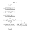
- FIG. 11 is a flowchart illustrating a method of delaying the operation of each load of a household appliance in response to a current DR level in a DR system according to example embodiments.
- the DR controller 28 may receive power rate information from the smartmeter 10 through the receiving unit 22 at operation 300.
- the DR controller 28 may establish a plurality of DR levels through the DR level setup unit 60 at operation 301.
- the DR level may have four levels (i.e., first to fourth DR levels), and have different power rates and different allowed amounts of power.
- the power rate to be assessed may be gradually increased and established.
- the DR controller 28 may recognize a current DR level of the household appliance at operation 302.
- the DR controller 28 may compare the recognized current DR level with a predetermined DR level, and determine whether the current DR level is high in level at operation 303. For example, if the DR level is a third DR level or a fourth DR level, this means that the current DR level is high.
- the DR controller 28 may delay the operation of a high-power-consumption load at operation 304.
- the DR controller may normally operate the load at operation 305.
- the DR system may shift the start time point of the defrosting operation of a refrigerator from a high-DR-level interval to a low-DR-level interval, and may reduce power consumption during the high-DR-level interval, thereby reducing power rates.
- the DR system, computer-readable medium and method according to the example embodiments may operate a high-power-consumption load with a positive or negative initiation delay in a low-power-rate interval according to the electricity demand pattern, and may smooth a power peak point and reduce a power rate in case of a real-time power rate system.
- the DR system, computer-readable medium and method according to the example embodiments controls a high-power-consumption load to be pre-operated or post-operated in a low-power-rate interval according to the electricity demand pattern, and may consider unique characteristics and driving histories of household appliances and reflect a user's personality in the design of household appliances.
- the above-described embodiments may be recorded in non-transitory computer-readable media including program instructions to implement various operations embodied by a computer.
- the media may also include, alone or in combination with the program instructions, data files, data structures, and the like.
- Examples of computer-readable media include magnetic media such as hard disks, floppy disks, and magnetic tape; optical media such as CD ROM disks and DVDs; magneto-optical media such as optical disks; and hardware devices that are specially configured to store and perform program instructions, such as read-only memory (ROM), random access memory (RAM), flash memory, and the like.
- the computer-readable media may be a plurality of computer-readable storage devices in a distributed network, so that the program instructions are stored in the plurality of computer-readable storage devices and executed in a distributed fashion.
- the program instructions may be executed by one or more processors or processing devices.
- the computer-readable media may also be embodied in at least one application specific integrated circuit (ASIC) or Field Programmable Gate Array (FPGA). Examples of program instructions include both machine code, such as produced by a compiler, and files containing higher level code that may be executed by the computer using an interpreter.
- the described hardware devices may be configured to act as one or more software modules in order to perform the operations of the above-described exemplary embodiments, or vice versa.
Landscapes
- Engineering & Computer Science (AREA)
- Power Engineering (AREA)
- Business, Economics & Management (AREA)
- Health & Medical Sciences (AREA)
- Economics (AREA)
- Public Health (AREA)
- Water Supply & Treatment (AREA)
- General Health & Medical Sciences (AREA)
- Human Resources & Organizations (AREA)
- Marketing (AREA)
- Primary Health Care (AREA)
- Strategic Management (AREA)
- Tourism & Hospitality (AREA)
- Physics & Mathematics (AREA)
- General Business, Economics & Management (AREA)
- General Physics & Mathematics (AREA)
- Theoretical Computer Science (AREA)
- Supply And Distribution Of Alternating Current (AREA)
- Remote Monitoring And Control Of Power-Distribution Networks (AREA)
Applications Claiming Priority (1)
| Application Number | Priority Date | Filing Date | Title |
|---|---|---|---|
| KR1020100015403A KR101702838B1 (ko) | 2010-02-19 | 2010-02-19 | 수요 반응 방법 및 수요 반응 시스템 |
Publications (2)
| Publication Number | Publication Date |
|---|---|
| EP2365600A2 true EP2365600A2 (de) | 2011-09-14 |
| EP2365600A3 EP2365600A3 (de) | 2016-09-14 |
Family
ID=44259962
Family Applications (1)
| Application Number | Title | Priority Date | Filing Date |
|---|---|---|---|
| EP11153296.6A Ceased EP2365600A3 (de) | 2010-02-19 | 2011-02-04 | Verfahren, computerlesbares Medium und System für Lastmanagement |
Country Status (4)
| Country | Link |
|---|---|
| US (1) | US8930033B2 (de) |
| EP (1) | EP2365600A3 (de) |
| KR (1) | KR101702838B1 (de) |
| CN (1) | CN102163305B (de) |
Cited By (2)
| Publication number | Priority date | Publication date | Assignee | Title |
|---|---|---|---|---|
| CN104035409A (zh) * | 2014-06-04 | 2014-09-10 | 国家电网公司 | 一种面向建筑楼宇能源优化运行的需求响应系统 |
| EP2674768A3 (de) * | 2012-06-12 | 2017-07-05 | LG Electronics, Inc. | Haushaltsgerät mit eingebautem Verbrauchsmessgerät |
Families Citing this family (39)
| Publication number | Priority date | Publication date | Assignee | Title |
|---|---|---|---|---|
| US8676953B2 (en) * | 2009-07-17 | 2014-03-18 | Honeywell International Inc. | Use of aggregated groups for managing demand response resources |
| US8572230B2 (en) * | 2009-07-17 | 2013-10-29 | Honeywell International Inc. | System for using attributes to deploy demand response resources |
| KR20110099542A (ko) * | 2010-03-02 | 2011-09-08 | 삼성전자주식회사 | 수요 반응 시스템 |
| US8670875B2 (en) * | 2010-06-30 | 2014-03-11 | Siemens Corporation | PLC function block for automated demand response integration |
| US9292804B2 (en) * | 2010-11-25 | 2016-03-22 | Samsung Electronics Co., Ltd. | Energy management system with user interface |
| KR101764251B1 (ko) * | 2011-04-19 | 2017-08-04 | 삼성전자주식회사 | 전력 사용 상태 표시 방법 및 이를 적용한 휴대기기 |
| KR20120132117A (ko) * | 2011-05-27 | 2012-12-05 | 한국전자통신연구원 | 전자기기의 사용 특성을 이용하는 에너지 제어 장치 및 방법 |
| WO2013012547A1 (en) | 2011-06-30 | 2013-01-24 | Lutron Electronics Co., Inc. | Load control device having internet connectivity, and method of programming the same using a smart phone |
| US9544977B2 (en) | 2011-06-30 | 2017-01-10 | Lutron Electronics Co., Inc. | Method of programming a load control device using a smart phone |
| US9386666B2 (en) | 2011-06-30 | 2016-07-05 | Lutron Electronics Co., Inc. | Method of optically transmitting digital information from a smart phone to a control device |
| US20130222122A1 (en) | 2011-08-29 | 2013-08-29 | Lutron Electronics Co., Inc. | Two-Part Load Control System Mountable To A Single Electrical Wallbox |
| US20130066482A1 (en) * | 2011-09-13 | 2013-03-14 | Samsung Electronics Co., Ltd. | Apparatus and method for executing energy demand response process in an electrical power network |
| JP5917132B2 (ja) * | 2011-12-22 | 2016-05-11 | 株式会社東芝 | 電気機器の運転制御システム及び方法 |
| US9235825B2 (en) * | 2012-03-05 | 2016-01-12 | Green Charge Neworks LLC | Processing load profiles for consumption management systems |
| JP5643791B2 (ja) * | 2012-07-23 | 2014-12-17 | 株式会社東芝 | 電力需給制御装置及び電力需給制御方法 |
| US9141102B2 (en) * | 2012-12-06 | 2015-09-22 | General Electric Company | Method and system for scheduling appliance operation during off-peak demand periods |
| US9413171B2 (en) | 2012-12-21 | 2016-08-09 | Lutron Electronics Co., Inc. | Network access coordination of load control devices |
| US10019047B2 (en) | 2012-12-21 | 2018-07-10 | Lutron Electronics Co., Inc. | Operational coordination of load control devices for control of electrical loads |
| US10244086B2 (en) | 2012-12-21 | 2019-03-26 | Lutron Electronics Co., Inc. | Multiple network access load control devices |
| EP2965397A4 (de) * | 2013-03-07 | 2016-12-14 | Siemens Corp | Nachfrageformung in einem stromnetz mit folgetagmarktpreisen und echtzeitmarktpreisen |
| EP2965282B1 (de) | 2013-03-07 | 2019-10-30 | Siemens Corporation | Nachfrageformung in einem stromnetz |
| JP2014180187A (ja) * | 2013-03-15 | 2014-09-25 | Toshiba Corp | 電力需要予測装置、方法及びプログラム並びに需要抑制計画策定装置 |
| US10135629B2 (en) | 2013-03-15 | 2018-11-20 | Lutron Electronics Co., Inc. | Load control device user interface and database management using near field communication (NFC) |
| US9366702B2 (en) * | 2013-08-23 | 2016-06-14 | Green Edge Technologies, Inc. | Devices and methods for determining whether an electrical device or component can sustain variations in voltage |
| SG11201500154YA (en) | 2013-09-11 | 2015-04-29 | Toshiba Kk | Battery controller, management system, battery control method, battery control program, and storage medium |
| TR201720276T3 (tr) * | 2013-11-01 | 2019-05-21 | Arcelik As | İyi̇leşti̇ri̇lmi̇ş enerji̇ yöneti̇m modu i̇çeren buzdolabi ve buzdolabi kontrol yöntemi̇ |
| US9891905B2 (en) * | 2014-02-10 | 2018-02-13 | General Electric Company | Utility meter intelligent firmware update system and method |
| CN104218683B (zh) * | 2014-10-11 | 2016-03-23 | 重庆邮电大学 | 一种闭环自学习需求响应系统及方法 |
| KR20170000732A (ko) | 2015-06-24 | 2017-01-03 | 주식회사 디피안 | 인터넷을 이용한 원격 도면작성 운용 방법 |
| JP6757915B2 (ja) * | 2015-07-30 | 2020-09-23 | パナソニックIpマネジメント株式会社 | 情報端末の制御方法および情報システム |
| US10054918B2 (en) | 2015-08-25 | 2018-08-21 | Engie Storage Services Na Llc | Emulator for optimizing energy consumption management systems |
| KR102638339B1 (ko) * | 2016-01-27 | 2024-02-19 | 주식회사 케이티 | 지능형 수요 반응 입찰 관리 시스템 및 그 방법 |
| US10999652B2 (en) | 2017-05-24 | 2021-05-04 | Engie Storage Services Na Llc | Energy-based curtailment systems and methods |
| US10658841B2 (en) | 2017-07-14 | 2020-05-19 | Engie Storage Services Na Llc | Clustered power generator architecture |
| JP7311319B2 (ja) * | 2019-06-19 | 2023-07-19 | ファナック株式会社 | 時系列データ表示装置 |
| US12437347B1 (en) * | 2019-07-31 | 2025-10-07 | West Technology Group, Llc | Energy usage tracking and management |
| CN111047141B (zh) * | 2019-11-14 | 2024-04-16 | 中国电力科学研究院有限公司 | 用于需求响应资源普查的云数据平台、手持客户端及方法 |
| CN114462725B (zh) * | 2022-04-13 | 2022-09-02 | 国网浙江省电力有限公司营销服务中心 | 一种基于动态资源池的非直控型需求侧响应优化调度方法 |
| WO2024117277A1 (ko) * | 2022-11-28 | 2024-06-06 | 주식회사 이아이피그리드 | 다중 수용가 게이트웨이 통합 운영 시스템 및 그 방법 |
Family Cites Families (28)
| Publication number | Priority date | Publication date | Assignee | Title |
|---|---|---|---|---|
| EP0808012A1 (de) * | 1992-07-03 | 1997-11-19 | EURO CP s.a.r.l. | Verfahren zur Steuerung der Stromverbrauchzählung in einer örtlichen Netzwerkanordnung |
| NO309550B1 (no) * | 1998-04-07 | 2001-02-12 | It & Process As | System for styring av effektforbruk hos en bruker av elektrisk effekt |
| AUPQ957600A0 (en) * | 2000-08-21 | 2000-09-14 | Perera, Anil Lasantha Michael | Method to enable customers to respond to prices in a pool type market |
| EP1263108A1 (de) * | 2001-06-01 | 2002-12-04 | Roke Manor Research Limited | Energieverwaltungssystem für eine Gemeinschaft |
| JP2003111311A (ja) * | 2001-09-26 | 2003-04-11 | Toyota Industries Corp | 電力コスト低減装置及び電力コスト低減方法 |
| JP3948253B2 (ja) | 2001-11-12 | 2007-07-25 | セイコーエプソン株式会社 | 電力需給システムおよび電力需給方法 |
| US6631622B1 (en) * | 2002-03-22 | 2003-10-14 | Whirlpool Corporation | Demand side management of freezer systems |
| US7561977B2 (en) * | 2002-06-13 | 2009-07-14 | Whirlpool Corporation | Total home energy management system |
| EP1441430B1 (de) * | 2003-01-21 | 2015-05-06 | Whirlpool Corporation | Verfahren zur Verwaltung und zur Beschränkung des Leistungsbedarfs von Geräte und deren Komponenten, und dasselbe Verfahren gebrauchendes System |
| JP4212369B2 (ja) | 2003-01-22 | 2009-01-21 | 中国電力株式会社 | 電力供給サービス方法およびシステム |
| US20040215529A1 (en) * | 2004-04-16 | 2004-10-28 | Foster Andre E. | System and method for energy price forecasting automation |
| KR100725178B1 (ko) * | 2004-10-30 | 2007-06-04 | 한국전력공사 | 전력선 통신을 이용한 전력부가 서비스 시스템 및 방법 |
| JP2007129873A (ja) | 2005-11-07 | 2007-05-24 | Nippon Telegr & Teleph Corp <Ntt> | エネルギー需要管理装置および方法 |
| JP4757151B2 (ja) * | 2006-09-06 | 2011-08-24 | 中国電力株式会社 | 電気機器の制御システム |
| US20080177678A1 (en) * | 2007-01-24 | 2008-07-24 | Paul Di Martini | Method of communicating between a utility and its customer locations |
| JP5288782B2 (ja) * | 2007-03-09 | 2013-09-11 | 三洋電機株式会社 | デマンド制御システム、デマンドコントローラ、デマンドプログラム及びデマンド制御方法 |
| JP2008236913A (ja) | 2007-03-20 | 2008-10-02 | Sanyo Electric Co Ltd | 電力制御システム、デマンドコントローラ、デマンドプログラム及び電力制御方法 |
| US8131403B2 (en) * | 2007-08-28 | 2012-03-06 | Consert, Inc. | System and method for determining and utilizing customer energy profiles for load control for individual structures, devices, and aggregation of same |
| JP5054590B2 (ja) | 2008-03-26 | 2012-10-24 | パナソニック株式会社 | デマンド制御システム、デマンド制御方法 |
| KR20090126104A (ko) * | 2008-06-03 | 2009-12-08 | 서울대학교산학협력단 | 전력 수요 관리 방법 및 시스템 |
| US8204633B2 (en) * | 2008-07-01 | 2012-06-19 | Carina Technology, Inc. | Water heater demand side management system |
| US20110231320A1 (en) * | 2009-12-22 | 2011-09-22 | Irving Gary W | Energy management systems and methods |
| CA2731433C (en) * | 2010-02-09 | 2018-05-15 | Open Access Technology International, Inc. | Systems and methods for demand response and distributed energy resource management |
| US20120083930A1 (en) * | 2010-09-30 | 2012-04-05 | Robert Bosch Gmbh | Adaptive load management: a system for incorporating customer electrical demand information for demand and supply side energy management |
| US9837821B2 (en) * | 2011-03-25 | 2017-12-05 | Green Charge Networks Llc | Energy allocation for energy storage cooperation |
| US20130144451A1 (en) * | 2011-10-25 | 2013-06-06 | San Diego State University Research Foundation | Residential and commercial energy management system |
| US9235825B2 (en) * | 2012-03-05 | 2016-01-12 | Green Charge Neworks LLC | Processing load profiles for consumption management systems |
| US8849715B2 (en) * | 2012-10-24 | 2014-09-30 | Causam Energy, Inc. | System, method, and apparatus for settlement for participation in an electric power grid |
-
2010
- 2010-02-19 KR KR1020100015403A patent/KR101702838B1/ko active Active
-
2011
- 2011-02-04 EP EP11153296.6A patent/EP2365600A3/de not_active Ceased
- 2011-02-16 US US12/929,803 patent/US8930033B2/en active Active
- 2011-02-18 CN CN201110041853.6A patent/CN102163305B/zh not_active Expired - Fee Related
Non-Patent Citations (1)
| Title |
|---|
| None |
Cited By (4)
| Publication number | Priority date | Publication date | Assignee | Title |
|---|---|---|---|---|
| EP2674768A3 (de) * | 2012-06-12 | 2017-07-05 | LG Electronics, Inc. | Haushaltsgerät mit eingebautem Verbrauchsmessgerät |
| US9797934B2 (en) | 2012-06-12 | 2017-10-24 | Lg Electronics Inc. | Home appliance having built-in power meter |
| CN104035409A (zh) * | 2014-06-04 | 2014-09-10 | 国家电网公司 | 一种面向建筑楼宇能源优化运行的需求响应系统 |
| CN104035409B (zh) * | 2014-06-04 | 2017-02-01 | 国家电网公司 | 一种面向建筑楼宇能源优化运行的需求响应系统 |
Also Published As
| Publication number | Publication date |
|---|---|
| CN102163305B (zh) | 2016-06-29 |
| KR20110095758A (ko) | 2011-08-25 |
| EP2365600A3 (de) | 2016-09-14 |
| CN102163305A (zh) | 2011-08-24 |
| KR101702838B1 (ko) | 2017-02-07 |
| US20110208369A1 (en) | 2011-08-25 |
| US8930033B2 (en) | 2015-01-06 |
Similar Documents
| Publication | Publication Date | Title |
|---|---|---|
| US8930033B2 (en) | Demand response method, computer-readable medium and system | |
| EP2375527B1 (de) | Anfrageantwortverfahren und Anfrageantwortsystem | |
| Li et al. | User-expected price-based demand response algorithm for a home-to-grid system | |
| Lakshmanan et al. | Electric water heater flexibility potential and activation impact in system operator perspective–Norwegian scenario case study | |
| US9153965B2 (en) | System and method for energy storage management | |
| Adhikari et al. | An algorithm for optimal management of aggregated HVAC power demand using smart thermostats | |
| Soares et al. | A customized evolutionary algorithm for multiobjective management of residential energy resources | |
| Rastegar et al. | Load commitment in a smart home | |
| JP5643791B2 (ja) | 電力需給制御装置及び電力需給制御方法 | |
| US8571720B2 (en) | Supply-demand balance controller | |
| EP2437368B1 (de) | Elektrisches Gerät, Leistungsverwaltungssystem mit dem elektrischen Gerät und Verfahren zu seiner Steuerung | |
| EP2487768B1 (de) | Elektrische Vorrichtung und Vorrichtung zur Leistungspegelregelung zur Veränderung der Leitebene der Anforderungsantwort (DR) | |
| JP6302197B2 (ja) | 電力需給制御装置及び電力需給制御方法 | |
| EP2667472A1 (de) | Strombedarfs-regelungsvorrichtung, stromregelungs-netzwerksystem und stromregelungsverfahren | |
| US9537317B2 (en) | Power management system and method for controlling the same | |
| CN117613976A (zh) | 一种储能供电控制方法、户用储能设备和存储介质 | |
| CN102279572B (zh) | 需求响应方法和需求响应系统 | |
| CN106125563A (zh) | 家电设备的控制方法、控制装置及家电设备 | |
| Arafat et al. | Maximum reserved capacity of aggregated electric water heaters virtual battery for peak management | |
| JP2017198374A (ja) | 管理装置、計画方法及び制御プログラム | |
| CN108063438A (zh) | 直流微电网系统的控制方法和装置 | |
| US20120101646A1 (en) | Interactive system for price-point control of power consumption | |
| US9407114B2 (en) | Network system and control method thereof | |
| Reymond et al. | Reinforcement learning for demand response of domestic household appliances | |
| CN112859956B (zh) | 温度调节设备的控制方法和装置 |
Legal Events
| Date | Code | Title | Description |
|---|---|---|---|
| PUAI | Public reference made under article 153(3) epc to a published international application that has entered the european phase |
Free format text: ORIGINAL CODE: 0009012 |
|
| AK | Designated contracting states |
Kind code of ref document: A2 Designated state(s): AL AT BE BG CH CY CZ DE DK EE ES FI FR GB GR HR HU IE IS IT LI LT LU LV MC MK MT NL NO PL PT RO RS SE SI SK SM TR |
|
| AX | Request for extension of the european patent |
Extension state: BA ME |
|
| RAP1 | Party data changed (applicant data changed or rights of an application transferred) |
Owner name: SAMSUNG ELECTRONICS CO., LTD. |
|
| PUAL | Search report despatched |
Free format text: ORIGINAL CODE: 0009013 |
|
| AK | Designated contracting states |
Kind code of ref document: A3 Designated state(s): AL AT BE BG CH CY CZ DE DK EE ES FI FR GB GR HR HU IE IS IT LI LT LU LV MC MK MT NL NO PL PT RO RS SE SI SK SM TR |
|
| AX | Request for extension of the european patent |
Extension state: BA ME |
|
| RIC1 | Information provided on ipc code assigned before grant |
Ipc: H02J 3/14 20060101AFI20160808BHEP |
|
| STAA | Information on the status of an ep patent application or granted ep patent |
Free format text: STATUS: REQUEST FOR EXAMINATION WAS MADE |
|
| 17P | Request for examination filed |
Effective date: 20170314 |
|
| RBV | Designated contracting states (corrected) |
Designated state(s): AL AT BE BG CH CY CZ DE DK EE ES FI FR GB GR HR HU IE IS IT LI LT LU LV MC MK MT NL NO PL PT RO RS SE SI SK SM TR |
|
| STAA | Information on the status of an ep patent application or granted ep patent |
Free format text: STATUS: EXAMINATION IS IN PROGRESS |
|
| 17Q | First examination report despatched |
Effective date: 20180226 |
|
| STAA | Information on the status of an ep patent application or granted ep patent |
Free format text: STATUS: THE APPLICATION HAS BEEN REFUSED |
|
| 18R | Application refused |
Effective date: 20210211 |