EP2365613B1 - Vorrichtung zum Fixieren von Endspulenteilen eines Stators gegen Vibrationen - Google Patents
Vorrichtung zum Fixieren von Endspulenteilen eines Stators gegen Vibrationen Download PDFInfo
- Publication number
- EP2365613B1 EP2365613B1 EP10155719A EP10155719A EP2365613B1 EP 2365613 B1 EP2365613 B1 EP 2365613B1 EP 10155719 A EP10155719 A EP 10155719A EP 10155719 A EP10155719 A EP 10155719A EP 2365613 B1 EP2365613 B1 EP 2365613B1
- Authority
- EP
- European Patent Office
- Prior art keywords
- screw
- trapezoidal
- end winding
- seats
- winding parts
- Prior art date
- Legal status (The legal status is an assumption and is not a legal conclusion. Google has not performed a legal analysis and makes no representation as to the accuracy of the status listed.)
- Not-in-force
Links
Images

Classifications
-
- H—ELECTRICITY
- H02—GENERATION; CONVERSION OR DISTRIBUTION OF ELECTRIC POWER
- H02K—DYNAMO-ELECTRIC MACHINES
- H02K3/00—Details of windings
- H02K3/46—Fastening of windings on the stator or rotor structure
- H02K3/50—Fastening of winding heads, equalising connectors, or connections thereto
- H02K3/505—Fastening of winding heads, equalising connectors, or connections thereto for large machine windings, e.g. bar windings
-
- F—MECHANICAL ENGINEERING; LIGHTING; HEATING; WEAPONS; BLASTING
- F16—ENGINEERING ELEMENTS AND UNITS; GENERAL MEASURES FOR PRODUCING AND MAINTAINING EFFECTIVE FUNCTIONING OF MACHINES OR INSTALLATIONS; THERMAL INSULATION IN GENERAL
- F16B—DEVICES FOR FASTENING OR SECURING CONSTRUCTIONAL ELEMENTS OR MACHINE PARTS TOGETHER, e.g. NAILS, BOLTS, CIRCLIPS, CLAMPS, CLIPS OR WEDGES; JOINTS OR JOINTING
- F16B2/00—Friction-grip releasable fastenings
- F16B2/02—Clamps, i.e. with gripping action effected by positive means other than the inherent resistance to deformation of the material of the fastening
- F16B2/04—Clamps, i.e. with gripping action effected by positive means other than the inherent resistance to deformation of the material of the fastening internal, i.e. with spreading action
Definitions
- the present invention relates to a device for connecting together end winding parts of stator bars.
- Stator bars are known to comprise straight parts or slot parts that are inserted in slots of the stator, and end winding parts that are usually bent with respect to the straight parts and are electrically connected together.
- the end winding parts 1 have an involute portion 3 and a terminal straight portion 5.
- Connection between adjacent end winding parts 1 is achieved at the terminal straight portions 5 via insulation caps that realise the electric connections between the stator bars.
- Vibration may damage connection of the end winding parts 1 to the phase rings and may cause insulation and/or bars to be damaged.
- stator bars may be provided with plastic blocks between the involute portions 3 of the end windings parts 1 for blocking them together.
- These plastic blocks typically have a fixed dimension and are provided with holes in which connecting laces are inserted.
- FR 2 320 653 discloses a device for blocking the end windings of stator bars of a rotating electric machine.
- This device has a trapezoidal element between side elements. The trapezoidal element is brought in position by a screw that is then removed. The trapezoidal element is then blocked by a lacing wrapped to a bar of the electric machine.
- US 942 326 discloses a device fir blocking the end windings of stator bars comprising first and second elements having sloped facingstructure and one trapezoidal cursor fixed by a sreen.
- the technical aim of the present invention is therefore to provide a device by which the said problems of the known art are eliminated.
- an aspect of the invention is to provide a device that is able to firmly block end winding parts of stator bars together, with no or only limited risk that during operation firm connection is lost.
- Another aspect of the invention is to provide a device that during operation of an electric generator prevents vibration generation.
- these show a device 10 for connecting together end winding parts 1 of stator bars 2 of an electric generator.
- the device 10 is arranged for stiffening the end winding parts of a generator.
- the device 10 comprises a first and a second element 11, 12 that are movable apart from one another to regulate the device dimension, to perfectly fit a gap between adjacent end winding parts.
- first and second element 11, 12 have sloped facing surfaces 13 defining trapezoidal seats housing trapezoidal cursors 14.
- screws 15 are axially fixed (i.e. along a longitudinal axis 16) and rotatably movable with respect to the first and second element 11, 12 and have threaded portions inserted in threaded through holes 17 of the cursors 14.
- the first and second element 11, 12 have sloped facing surfaces 13 defining two trapezoidal seats, and one cursor 14 is housed in each trapezoidal seat.
- the trapezoidal seats converge towards the other trapezoidal seat, i.e. the trapezoidal seats have the smaller basis that faces the other trapezoidal seat.
- the two trapezoidal seats are aligned along the longitudinal axis 16 of the device.
- the screws 15 have a guide portion 18 (defined by a disk with a diameter larger than the diameter of the screw) housed in recessed seats 19 of the first and second element 11, 12.
- figure 3 shows an embodiment in which one single screw 15 is provided; this screw 15 is inserted in the threaded through holes 17 of both cursors 14 and it is also provided with the guide portion 18 located centrally, that is slidingly inserted in the recessed seats 19 of the first and second element 11, 12.
- one of the holes 17 is right-hand threaded and the other is left-hand threaded and the screw 15 has corresponding threaded portions.
- FIG. 2 shows an embodiment similar to the one already described and in which like reference numbers identifies similar components; in addition, in this embodiment one screw 15 is inserted in the threaded through hole 17 of each cursor 14, such that two screws 15 are provided. Preferably, also in this embodiment one of the holes 17 of the cursors 14 is right-hand threaded and the other is left-hand threaded and the screws 15 have corresponding threaded portions.
- the two screws 15 are operable independently from one another and each of them has the guide portion 18 housed in the recessed seats 19 of the first and second element 11, 12.
- the two guide portions 18 of the two screws 15 are housed in the same seats 19 of the first and second element 11, 12.
- the outer surfaces of the first and second elements 11, 12 are padded, i.e. they are provided with soft pad, for example made of fibre glass (not shown).
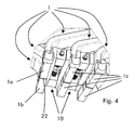
- the first and second element 11, 12 also have outer surfaces provided with ribs 20 insertable between adjoining end winding parts 1 when the devices 10 are mounted on an electric generator.
- the ribs are preferably provided with holes 21 that allow the device to be secured, for example by means of cords.
- the device 10 is made of insulating material and, thus, in particular, the first and second element 11 and 12, the screws 15 and the cursors 14 are made of an insulating material such as plastic or GRP or glass fibres embedded in a plastic matrix, and so on.
- the cursors 14 are in position apart from the centre of the device 10, such that the width of the device 10 is small and it can be inserted between the end winding parts 1.
- the ribs 20 are placed in the slits 22 between adjoining end winding parts 1a, 1b. It is anyhow clear that when needed the devices 10 can also be located between the insulation caps.
- securing means such as adhesive or resin-impregnated cords are provided in order to block the screws 15.
- the embodiment shown in figure 2 is particularly advantageous, since regulation of each screw 15 is possible independently from the other; in other words, when regulating the device 10, the first and second element 11 and 12 need not be parallel one to the other, but they may also rotate to perfectly fir the gap between the adjacent end winding parts 1c.
- a device may be inserted every gap, or every other gap, or only in positions where large vibration are measured during tests or calculations.
- the number of devices connected on a generator can be reduced by connecting a device 10 every second connection between end winding parts; the other connections can be achieved through blocks having fixed dimensions.
Landscapes
- Engineering & Computer Science (AREA)
- Power Engineering (AREA)
- Insulation, Fastening Of Motor, Generator Windings (AREA)
- Manufacture Of Motors, Generators (AREA)
Claims (13)
- Vorrichtung (10) zum Verbinden von Endspulenteilen (1) von Statorstäben (2) eines elektrischen Generators miteinander, wobei die Vorrichtung (10) ein erstes und ein zweites Element (11, 12) umfasst, die sich voneinander weg bewegen können, um die Vorrichtungsabmessungen zu regulieren,
wobei das erste und zweite Element (11, 12) geneigte, einander zugewandte Flächen (13) haben und mindestens eine Schraube (15) axial fixiert und drehbar gegenüber dem ersten und zweiten Element (11, 12) ist und einen Gewindeteil hat, der in ein Durchgangsloch (17) mit Gewinde des Läufers (14) eingeführt ist,
dadurch gekennzeichnet, dass die geneigten Flächen zwei trapezartige Aufnahmeflächen definieren, von denen jede einen trapezartigen Läufer (14) beherbergt, und dass die Vorrichtung (10) ferner Mittel zum Zusammenhalten des ersten und zweiten Elementes (11, 12), der Läufer (14) und der Schraube (15) umfasst. - Vorrichtung (10) nach Anspruch 1, dadurch gekennzeichnet, dass das erste und zweite Element (11, 12) geneigte, einander zugewandte Flächen (13) haben, die zwei trapezartige Aufnahmeflächen definieren, und dass ein Läufer (14) in jeder trapezartigen Fläche aufgenommen ist.
- Vorrichtung (10) nach Anspruch 2, dadurch gekennzeichnet, dass jede trapezartige Aufnahmefläche sich der anderen trapezartigen Aufnahmefläche nähert.
- Vorrichtung (10) nach Anspruch 3, dadurch gekennzeichnet, dass die zwei trapezartigen Aufnahmeflächen entlang einer Längsachse (16) der Vorrichtung (10) ausgerichtet sind.
- Vorrichtung (10) nach Anspruch 1, dadurch gekennzeichnet, dass zumindest eine Schraube (15) einen Führungsteil (18) hat, der in vertieften Aufnahmeflächen (19) des ersten und zweiten Elementes (11, 12) aufgenommen wird.
- Vorrichtung (10) nach Anspruch 5, dadurch gekennzeichnet, dass eine einzelne Schraube (15) vorgesehen ist, wobei diese Schraube (15) in die mit Gewinde versehenen Durchgangslöcher (17) beider Läufer (14) eingeführt ist.
- Vorrichtung (10) nach Anspruch 5, dadurch gekennzeichnet, dass eine Schraube (15) in das mit Gewinde versehene Durchgangsloch (17) jedes Läufers (14) eingeführt ist, wobei die zwei Schrauben (15) unabhängig voneinander bedient werden können.
- Vorrichtung (10) nach Anspruch 7, dadurch gekennzeichnet, dass jede Schraube (15) einen Führungsteil (18) hat, der in vertieften Aufnahmeflächen (19) des ersten und zweiten Elementes (11, 12) aufgenommen ist.
- Vorrichtung (10) nach Anspruch 8, dadurch gekennzeichnet, dass die Führungsteile (18) beider Schrauben (15) in denselben Aufnahmeflächen des ersten und zweiten Elementes (11, 12) aufgenommen sind.
- Vorrichtung (10) nach Anspruch 1, dadurch gekennzeichnet, dass das erste und zweite Element (11, 12) Außenflächen haben, die mit Rippen (20) versehen sind, welche zwischen benachbarten Endwicklungsteilen (1) eingeführt werden können.
- Vorrichtung (10) nach Anspruch 1, dadurch gekennzeichnet, dass das erste und zweite Element (11, 12), die Schrauben (15) und die Läufer (14) aus einem Isoliermaterial hergestellt sind.
- Vorrichtung (10) nach Anspruch 10, dadurch gekennzeichnet, dass die Rippen (20) mit Löchern (21) versehen sind, die ermöglichen, die Vorrichtung zu befestigen.
- Vorrichtung (10) nach Anspruch 1, dadurch gekennzeichnet, dass das Befestigungsmittel, wie zum Beispiel Klebstoff oder harzimprägnierte Schnüre, vorgesehen sind, um die Schrauben (15) zu blockieren.
Priority Applications (4)
| Application Number | Priority Date | Filing Date | Title |
|---|---|---|---|
| EP10155719A EP2365613B1 (de) | 2010-03-08 | 2010-03-08 | Vorrichtung zum Fixieren von Endspulenteilen eines Stators gegen Vibrationen |
| US13/033,691 US8441166B2 (en) | 2010-03-08 | 2011-02-24 | Device for connecting together end winding parts of stator |
| JP2011045990A JP2011188735A (ja) | 2010-03-08 | 2011-03-03 | 固定子の複数のコイル端部を一緒に結合するための装置 |
| CN201110054187XA CN102195416A (zh) | 2010-03-08 | 2011-03-04 | 用于将定子线棒的端部绕组部连接在一起的装置 |
Applications Claiming Priority (1)
| Application Number | Priority Date | Filing Date | Title |
|---|---|---|---|
| EP10155719A EP2365613B1 (de) | 2010-03-08 | 2010-03-08 | Vorrichtung zum Fixieren von Endspulenteilen eines Stators gegen Vibrationen |
Publications (2)
| Publication Number | Publication Date |
|---|---|
| EP2365613A1 EP2365613A1 (de) | 2011-09-14 |
| EP2365613B1 true EP2365613B1 (de) | 2012-11-28 |
Family
ID=42341647
Family Applications (1)
| Application Number | Title | Priority Date | Filing Date |
|---|---|---|---|
| EP10155719A Not-in-force EP2365613B1 (de) | 2010-03-08 | 2010-03-08 | Vorrichtung zum Fixieren von Endspulenteilen eines Stators gegen Vibrationen |
Country Status (4)
| Country | Link |
|---|---|
| US (1) | US8441166B2 (de) |
| EP (1) | EP2365613B1 (de) |
| JP (1) | JP2011188735A (de) |
| CN (1) | CN102195416A (de) |
Families Citing this family (1)
| Publication number | Priority date | Publication date | Assignee | Title |
|---|---|---|---|---|
| WO2016004616A1 (zh) * | 2014-07-11 | 2016-01-14 | 嘉华金属(上海)有限公司 | 异形管的迫紧连接装置 |
Family Cites Families (12)
| Publication number | Priority date | Publication date | Assignee | Title |
|---|---|---|---|---|
| US906A (en) * | 1838-09-05 | Steam-boiler | ||
| CH436857A (de) * | 1966-01-14 | 1967-05-31 | Schrepfer Rudolf | Nivellierschuh |
| FR2287798A1 (fr) * | 1974-10-08 | 1976-05-07 | Alsthom Cgee | Disposition de fixation de barres d'enroulement sur un stator de machine electrique tournante |
| FR2320653A1 (fr) * | 1975-08-07 | 1977-03-04 | Alsthom Cgee | Dispositif d'immobilisation des sorties des barres d'enroulements statoriques d'une machine electrique tournante |
| GB2093517B (en) * | 1981-02-21 | 1986-01-02 | Ibrahim Kemal | Securing means |
| US4480287A (en) * | 1982-12-27 | 1984-10-30 | Raytheon Company | Module retainer apparatus |
| GB8306690D0 (en) * | 1983-03-11 | 1983-04-20 | Lucas Ind Plc | Motor operated mechanism |
| DE3612819A1 (de) * | 1986-04-16 | 1987-10-22 | Siemens Ag | Anordnung zur befestigung einer luftspaltwicklung und verfahren zu ihrer montage und demontage |
| US4942326A (en) * | 1989-04-19 | 1990-07-17 | Westinghouse Electric Corp. | Biased securement system for end winding conductor |
| USH906H (en) * | 1990-06-04 | 1991-04-02 | The United States Of America As Represented By The United States Department Of Energy | Wedge assembly for electrical transformer component spacing |
| SE9704423D0 (sv) * | 1997-02-03 | 1997-11-28 | Asea Brown Boveri | Roterande elektrisk maskin med spolstöd |
| US6695524B2 (en) * | 2001-11-19 | 2004-02-24 | Robert James Monson | Mount locking plate |
-
2010
- 2010-03-08 EP EP10155719A patent/EP2365613B1/de not_active Not-in-force
-
2011
- 2011-02-24 US US13/033,691 patent/US8441166B2/en not_active Expired - Fee Related
- 2011-03-03 JP JP2011045990A patent/JP2011188735A/ja not_active Withdrawn
- 2011-03-04 CN CN201110054187XA patent/CN102195416A/zh active Pending
Also Published As
| Publication number | Publication date |
|---|---|
| US8441166B2 (en) | 2013-05-14 |
| EP2365613A1 (de) | 2011-09-14 |
| US20110215663A1 (en) | 2011-09-08 |
| JP2011188735A (ja) | 2011-09-22 |
| CN102195416A (zh) | 2011-09-21 |
Similar Documents
| Publication | Publication Date | Title |
|---|---|---|
| GB2478191A (en) | Stator core suspension system with circumferential spring bar | |
| US10439463B2 (en) | Assembly and method for supporting generator stator end winding coils | |
| US10355551B2 (en) | Support element and stator assembly comprising the same | |
| KR101874115B1 (ko) | 다이나모일렉트릭 기계용 지지 시스템 | |
| JP2013530666A (ja) | 圧電電動機械のローター | |
| EP2365613B1 (de) | Vorrichtung zum Fixieren von Endspulenteilen eines Stators gegen Vibrationen | |
| US4379243A (en) | Stator end turn support system | |
| JP5366624B2 (ja) | 架空送電線用スペーサ | |
| US20150008781A1 (en) | Stator core support system | |
| CN102625973B (zh) | 机电机器 | |
| KR101707338B1 (ko) | 회전식 송배전 케이블의 지지장치 | |
| US8664813B2 (en) | Phase ring assembly | |
| JP5791572B2 (ja) | 回転電気機器 | |
| US9551598B2 (en) | Fiber optic sensing apparatus with an improved fiber-affixing device | |
| KR20120054538A (ko) | 회전 전기 기계용 연결 링 조립체 | |
| KR101203870B1 (ko) | 유도 전동기 | |
| KR101283651B1 (ko) | 대용량 초전도 회전기에 결합되는 모듈형 회전자 장치 | |
| US1197092A (en) | Dynamo-electric machine. | |
| US20130140925A1 (en) | Stator including conductors provided with a composite sleeve | |
| JP5762135B2 (ja) | コネクタ | |
| JP2009203936A (ja) | 電動圧縮機のケーブル接続構造 | |
| EP2562433A1 (de) | Rotor für eine elektrische Maschine und Schraube | |
| JP5610939B2 (ja) | 回転電機および回転電機の固定子 | |
| HK40060358B (en) | A slip ring assembly | |
| SE515721C2 (sv) | Roterande elektrisk maskin och förfarande vid tillverkning av en sådan |
Legal Events
| Date | Code | Title | Description |
|---|---|---|---|
| PUAI | Public reference made under article 153(3) epc to a published international application that has entered the european phase |
Free format text: ORIGINAL CODE: 0009012 |
|
| AK | Designated contracting states |
Kind code of ref document: A1 Designated state(s): AT BE BG CH CY CZ DE DK EE ES FI FR GB GR HR HU IE IS IT LI LT LU LV MC MK MT NL NO PL PT RO SE SI SK SM TR |
|
| AX | Request for extension of the european patent |
Extension state: AL BA ME RS |
|
| 17P | Request for examination filed |
Effective date: 20120309 |
|
| GRAP | Despatch of communication of intention to grant a patent |
Free format text: ORIGINAL CODE: EPIDOSNIGR1 |
|
| GRAS | Grant fee paid |
Free format text: ORIGINAL CODE: EPIDOSNIGR3 |
|
| GRAL | Information related to payment of fee for publishing/printing deleted |
Free format text: ORIGINAL CODE: EPIDOSDIGR3 |
|
| GRAS | Grant fee paid |
Free format text: ORIGINAL CODE: EPIDOSNIGR3 |
|
| GRAF | Information related to payment of grant fee modified |
Free format text: ORIGINAL CODE: EPIDOSCIGR3 |
|
| GRAA | (expected) grant |
Free format text: ORIGINAL CODE: 0009210 |
|
| AK | Designated contracting states |
Kind code of ref document: B1 Designated state(s): AT BE BG CH CY CZ DE DK EE ES FI FR GB GR HR HU IE IS IT LI LT LU LV MC MK MT NL NO PL PT RO SE SI SK SM TR |
|
| REG | Reference to a national code |
Ref country code: GB Ref legal event code: FG4D |
|
| REG | Reference to a national code |
Ref country code: CH Ref legal event code: EP |
|
| REG | Reference to a national code |
Ref country code: AT Ref legal event code: REF Ref document number: 586601 Country of ref document: AT Kind code of ref document: T Effective date: 20121215 |
|
| REG | Reference to a national code |
Ref country code: IE Ref legal event code: FG4D |
|
| REG | Reference to a national code |
Ref country code: DE Ref legal event code: R096 Ref document number: 602010003782 Country of ref document: DE Effective date: 20130117 |
|
| REG | Reference to a national code |
Ref country code: AT Ref legal event code: MK05 Ref document number: 586601 Country of ref document: AT Kind code of ref document: T Effective date: 20121128 |
|
| REG | Reference to a national code |
Ref country code: NL Ref legal event code: VDEP Effective date: 20121128 |
|
| REG | Reference to a national code |
Ref country code: LT Ref legal event code: MG4D |
|
| PG25 | Lapsed in a contracting state [announced via postgrant information from national office to epo] |
Ref country code: NO Free format text: LAPSE BECAUSE OF FAILURE TO SUBMIT A TRANSLATION OF THE DESCRIPTION OR TO PAY THE FEE WITHIN THE PRESCRIBED TIME-LIMIT Effective date: 20130228 Ref country code: FI Free format text: LAPSE BECAUSE OF FAILURE TO SUBMIT A TRANSLATION OF THE DESCRIPTION OR TO PAY THE FEE WITHIN THE PRESCRIBED TIME-LIMIT Effective date: 20121128 Ref country code: LT Free format text: LAPSE BECAUSE OF FAILURE TO SUBMIT A TRANSLATION OF THE DESCRIPTION OR TO PAY THE FEE WITHIN THE PRESCRIBED TIME-LIMIT Effective date: 20121128 Ref country code: SE Free format text: LAPSE BECAUSE OF FAILURE TO SUBMIT A TRANSLATION OF THE DESCRIPTION OR TO PAY THE FEE WITHIN THE PRESCRIBED TIME-LIMIT Effective date: 20121128 Ref country code: ES Free format text: LAPSE BECAUSE OF FAILURE TO SUBMIT A TRANSLATION OF THE DESCRIPTION OR TO PAY THE FEE WITHIN THE PRESCRIBED TIME-LIMIT Effective date: 20130311 |
|
| PG25 | Lapsed in a contracting state [announced via postgrant information from national office to epo] |
Ref country code: BE Free format text: LAPSE BECAUSE OF FAILURE TO SUBMIT A TRANSLATION OF THE DESCRIPTION OR TO PAY THE FEE WITHIN THE PRESCRIBED TIME-LIMIT Effective date: 20121128 Ref country code: PT Free format text: LAPSE BECAUSE OF FAILURE TO SUBMIT A TRANSLATION OF THE DESCRIPTION OR TO PAY THE FEE WITHIN THE PRESCRIBED TIME-LIMIT Effective date: 20130328 Ref country code: GR Free format text: LAPSE BECAUSE OF FAILURE TO SUBMIT A TRANSLATION OF THE DESCRIPTION OR TO PAY THE FEE WITHIN THE PRESCRIBED TIME-LIMIT Effective date: 20130301 Ref country code: LV Free format text: LAPSE BECAUSE OF FAILURE TO SUBMIT A TRANSLATION OF THE DESCRIPTION OR TO PAY THE FEE WITHIN THE PRESCRIBED TIME-LIMIT Effective date: 20121128 Ref country code: PL Free format text: LAPSE BECAUSE OF FAILURE TO SUBMIT A TRANSLATION OF THE DESCRIPTION OR TO PAY THE FEE WITHIN THE PRESCRIBED TIME-LIMIT Effective date: 20121128 Ref country code: SI Free format text: LAPSE BECAUSE OF FAILURE TO SUBMIT A TRANSLATION OF THE DESCRIPTION OR TO PAY THE FEE WITHIN THE PRESCRIBED TIME-LIMIT Effective date: 20121128 |
|
| PG25 | Lapsed in a contracting state [announced via postgrant information from national office to epo] |
Ref country code: AT Free format text: LAPSE BECAUSE OF FAILURE TO SUBMIT A TRANSLATION OF THE DESCRIPTION OR TO PAY THE FEE WITHIN THE PRESCRIBED TIME-LIMIT Effective date: 20121128 |
|
| PG25 | Lapsed in a contracting state [announced via postgrant information from national office to epo] |
Ref country code: BG Free format text: LAPSE BECAUSE OF FAILURE TO SUBMIT A TRANSLATION OF THE DESCRIPTION OR TO PAY THE FEE WITHIN THE PRESCRIBED TIME-LIMIT Effective date: 20130228 Ref country code: DK Free format text: LAPSE BECAUSE OF FAILURE TO SUBMIT A TRANSLATION OF THE DESCRIPTION OR TO PAY THE FEE WITHIN THE PRESCRIBED TIME-LIMIT Effective date: 20121128 Ref country code: SK Free format text: LAPSE BECAUSE OF FAILURE TO SUBMIT A TRANSLATION OF THE DESCRIPTION OR TO PAY THE FEE WITHIN THE PRESCRIBED TIME-LIMIT Effective date: 20121128 Ref country code: EE Free format text: LAPSE BECAUSE OF FAILURE TO SUBMIT A TRANSLATION OF THE DESCRIPTION OR TO PAY THE FEE WITHIN THE PRESCRIBED TIME-LIMIT Effective date: 20121128 Ref country code: CZ Free format text: LAPSE BECAUSE OF FAILURE TO SUBMIT A TRANSLATION OF THE DESCRIPTION OR TO PAY THE FEE WITHIN THE PRESCRIBED TIME-LIMIT Effective date: 20121128 |
|
| PG25 | Lapsed in a contracting state [announced via postgrant information from national office to epo] |
Ref country code: NL Free format text: LAPSE BECAUSE OF FAILURE TO SUBMIT A TRANSLATION OF THE DESCRIPTION OR TO PAY THE FEE WITHIN THE PRESCRIBED TIME-LIMIT Effective date: 20121128 Ref country code: RO Free format text: LAPSE BECAUSE OF FAILURE TO SUBMIT A TRANSLATION OF THE DESCRIPTION OR TO PAY THE FEE WITHIN THE PRESCRIBED TIME-LIMIT Effective date: 20121128 |
|
| PLBE | No opposition filed within time limit |
Free format text: ORIGINAL CODE: 0009261 |
|
| STAA | Information on the status of an ep patent application or granted ep patent |
Free format text: STATUS: NO OPPOSITION FILED WITHIN TIME LIMIT |
|
| PG25 | Lapsed in a contracting state [announced via postgrant information from national office to epo] |
Ref country code: MC Free format text: LAPSE BECAUSE OF NON-PAYMENT OF DUE FEES Effective date: 20130331 |
|
| 26N | No opposition filed |
Effective date: 20130829 |
|
| PG25 | Lapsed in a contracting state [announced via postgrant information from national office to epo] |
Ref country code: CY Free format text: LAPSE BECAUSE OF FAILURE TO SUBMIT A TRANSLATION OF THE DESCRIPTION OR TO PAY THE FEE WITHIN THE PRESCRIBED TIME-LIMIT Effective date: 20121128 |
|
| REG | Reference to a national code |
Ref country code: DE Ref legal event code: R097 Ref document number: 602010003782 Country of ref document: DE Effective date: 20130829 |
|
| REG | Reference to a national code |
Ref country code: FR Ref legal event code: ST Effective date: 20131129 |
|
| REG | Reference to a national code |
Ref country code: IE Ref legal event code: MM4A |
|
| PG25 | Lapsed in a contracting state [announced via postgrant information from national office to epo] |
Ref country code: FR Free format text: LAPSE BECAUSE OF NON-PAYMENT OF DUE FEES Effective date: 20130402 Ref country code: HR Free format text: LAPSE BECAUSE OF FAILURE TO SUBMIT A TRANSLATION OF THE DESCRIPTION OR TO PAY THE FEE WITHIN THE PRESCRIBED TIME-LIMIT Effective date: 20130731 Ref country code: IE Free format text: LAPSE BECAUSE OF NON-PAYMENT OF DUE FEES Effective date: 20130308 |
|
| PGFP | Annual fee paid to national office [announced via postgrant information from national office to epo] |
Ref country code: IT Payment date: 20140318 Year of fee payment: 5 |
|
| PG25 | Lapsed in a contracting state [announced via postgrant information from national office to epo] |
Ref country code: MT Free format text: LAPSE BECAUSE OF FAILURE TO SUBMIT A TRANSLATION OF THE DESCRIPTION OR TO PAY THE FEE WITHIN THE PRESCRIBED TIME-LIMIT Effective date: 20121128 |
|
| PGFP | Annual fee paid to national office [announced via postgrant information from national office to epo] |
Ref country code: GB Payment date: 20140225 Year of fee payment: 5 Ref country code: DE Payment date: 20140331 Year of fee payment: 5 |
|
| REG | Reference to a national code |
Ref country code: CH Ref legal event code: PL |
|
| PG25 | Lapsed in a contracting state [announced via postgrant information from national office to epo] |
Ref country code: LI Free format text: LAPSE BECAUSE OF NON-PAYMENT OF DUE FEES Effective date: 20140331 Ref country code: CH Free format text: LAPSE BECAUSE OF NON-PAYMENT OF DUE FEES Effective date: 20140331 |
|
| REG | Reference to a national code |
Ref country code: DE Ref legal event code: R083 Ref document number: 602010003782 Country of ref document: DE |
|
| PG25 | Lapsed in a contracting state [announced via postgrant information from national office to epo] |
Ref country code: SM Free format text: LAPSE BECAUSE OF FAILURE TO SUBMIT A TRANSLATION OF THE DESCRIPTION OR TO PAY THE FEE WITHIN THE PRESCRIBED TIME-LIMIT Effective date: 20121128 |
|
| PG25 | Lapsed in a contracting state [announced via postgrant information from national office to epo] |
Ref country code: TR Free format text: LAPSE BECAUSE OF FAILURE TO SUBMIT A TRANSLATION OF THE DESCRIPTION OR TO PAY THE FEE WITHIN THE PRESCRIBED TIME-LIMIT Effective date: 20121128 |
|
| PG25 | Lapsed in a contracting state [announced via postgrant information from national office to epo] |
Ref country code: HU Free format text: LAPSE BECAUSE OF FAILURE TO SUBMIT A TRANSLATION OF THE DESCRIPTION OR TO PAY THE FEE WITHIN THE PRESCRIBED TIME-LIMIT; INVALID AB INITIO Effective date: 20100308 Ref country code: MK Free format text: LAPSE BECAUSE OF FAILURE TO SUBMIT A TRANSLATION OF THE DESCRIPTION OR TO PAY THE FEE WITHIN THE PRESCRIBED TIME-LIMIT Effective date: 20121128 Ref country code: LU Free format text: LAPSE BECAUSE OF NON-PAYMENT OF DUE FEES Effective date: 20130308 |
|
| REG | Reference to a national code |
Ref country code: DE Ref legal event code: R119 Ref document number: 602010003782 Country of ref document: DE |
|
| GBPC | Gb: european patent ceased through non-payment of renewal fee |
Effective date: 20150308 |
|
| PG25 | Lapsed in a contracting state [announced via postgrant information from national office to epo] |
Ref country code: IT Free format text: LAPSE BECAUSE OF NON-PAYMENT OF DUE FEES Effective date: 20150308 |
|
| PG25 | Lapsed in a contracting state [announced via postgrant information from national office to epo] |
Ref country code: DE Free format text: LAPSE BECAUSE OF NON-PAYMENT OF DUE FEES Effective date: 20151001 Ref country code: GB Free format text: LAPSE BECAUSE OF NON-PAYMENT OF DUE FEES Effective date: 20150308 |
|
| PG25 | Lapsed in a contracting state [announced via postgrant information from national office to epo] |
Ref country code: IS Free format text: LAPSE BECAUSE OF FAILURE TO SUBMIT A TRANSLATION OF THE DESCRIPTION OR TO PAY THE FEE WITHIN THE PRESCRIBED TIME-LIMIT Effective date: 20121128 |