EP2365696A2 - Procédé et dispositif pour réduire le bruit de couleur d'une image - Google Patents
Procédé et dispositif pour réduire le bruit de couleur d'une image Download PDFInfo
- Publication number
- EP2365696A2 EP2365696A2 EP11153675A EP11153675A EP2365696A2 EP 2365696 A2 EP2365696 A2 EP 2365696A2 EP 11153675 A EP11153675 A EP 11153675A EP 11153675 A EP11153675 A EP 11153675A EP 2365696 A2 EP2365696 A2 EP 2365696A2
- Authority
- EP
- European Patent Office
- Prior art keywords
- pixel
- weight
- ycbcr
- chrominance
- luminance
- Prior art date
- Legal status (The legal status is an assumption and is not a legal conclusion. Google has not performed a legal analysis and makes no representation as to the accuracy of the status listed.)
- Granted
Links
Images


Classifications
-
- H—ELECTRICITY
- H04—ELECTRIC COMMUNICATION TECHNIQUE
- H04N—PICTORIAL COMMUNICATION, e.g. TELEVISION
- H04N23/00—Cameras or camera modules comprising electronic image sensors; Control thereof
- H04N23/80—Camera processing pipelines; Components thereof
- H04N23/81—Camera processing pipelines; Components thereof for suppressing or minimising disturbance in the image signal generation
-
- H—ELECTRICITY
- H04—ELECTRIC COMMUNICATION TECHNIQUE
- H04N—PICTORIAL COMMUNICATION, e.g. TELEVISION
- H04N23/00—Cameras or camera modules comprising electronic image sensors; Control thereof
- H04N23/80—Camera processing pipelines; Components thereof
- H04N23/84—Camera processing pipelines; Components thereof for processing colour signals
-
- G—PHYSICS
- G06—COMPUTING OR CALCULATING; COUNTING
- G06T—IMAGE DATA PROCESSING OR GENERATION, IN GENERAL
- G06T5/00—Image enhancement or restoration
- G06T5/20—Image enhancement or restoration using local operators
-
- G—PHYSICS
- G06—COMPUTING OR CALCULATING; COUNTING
- G06T—IMAGE DATA PROCESSING OR GENERATION, IN GENERAL
- G06T5/00—Image enhancement or restoration
- G06T5/70—Denoising; Smoothing
-
- H—ELECTRICITY
- H04—ELECTRIC COMMUNICATION TECHNIQUE
- H04N—PICTORIAL COMMUNICATION, e.g. TELEVISION
- H04N9/00—Details of colour television systems
- H04N9/64—Circuits for processing colour signals
- H04N9/646—Circuits for processing colour signals for image enhancement, e.g. vertical detail restoration, cross-colour elimination, contour correction, chrominance trapping filters
-
- G—PHYSICS
- G06—COMPUTING OR CALCULATING; COUNTING
- G06T—IMAGE DATA PROCESSING OR GENERATION, IN GENERAL
- G06T2207/00—Indexing scheme for image analysis or image enhancement
- G06T2207/10—Image acquisition modality
- G06T2207/10024—Color image
-
- G—PHYSICS
- G06—COMPUTING OR CALCULATING; COUNTING
- G06T—IMAGE DATA PROCESSING OR GENERATION, IN GENERAL
- G06T2207/00—Indexing scheme for image analysis or image enhancement
- G06T2207/20—Special algorithmic details
- G06T2207/20024—Filtering details
- G06T2207/20032—Median filtering
Definitions
- the present invention relates generally to an image processing method and an image processing device, and more specifically, to a method and device for reducing image color noise captured by an image sensor.
- a digital camera or a camcorder uses an image sensor, such as a Charge Coupled Device (CCD), a Complementary Metal Oxide Semiconductor (CMOS), or the like, instead of using film.
- the CCD is classified into a multiple CCD and a single CCD depending to the number of colors focused on a pixel.
- a multiple CCD can provide more accurate luminance and more accurate matching with a primary color for each pixel, as compared to a single CCD.
- the multiple CCD uses at least three times as many sensors as those used in the single CCD in order to detect each color component according to used color formats, such that the hardware architecture becomes complex and increases hardware size. For this reason, the single CCD has been predominantly used rather than the multiple CCD.
- each pixel stores only one color information of RGB color channels. Therefore, in order to obtain the complete information on images, the color information of other color channels that is not stored in the pixel should be interpolated from pixel information adjacent to the pixel. However, when unwanted information is interpolated during the interpolation process, noise or artifacts, which are largely unpleasant to the eye, are generated in images.
- a noise reducing algorithm may be classified into a method using a restoration mechanism, a method using a filtering mechanism, and the like. Since the restoration mechanism depends on accurate modeling for noise, excellent results are obtained but the burden on hardware is increased. Therefore, a method of using local probabilistic characteristics, for example, Local Linear Minimum Mean Square Error (LLMMSE), or the like, has been primarily used. A relatively simple bilateral filter approximating the LLMMSE, and the like, has been primarily used.
- LLMMSE Local Linear Minimum Mean Square Error
- Equation (1) when the variance (var_noise) of noise is relatively larger than variance (var(in[r][c]) of signal, var (in[r][c])/(var_noise + var(in[r][c]) approximates "0" and the output out[r][c] approximates the mean accordingly, such that noise is reduced.
- var(in[r][c])/(var_noise + var(in[r][c])) approximates "1" and an output (out[r)[c]) approximates an original signal in [r][c] accordingly, such that noise is less reduced.
- color noise reducing filters may include a Mean Filter (MF), a Vector Median Filter (VMF), a Vector Directional Filter (VDF), and the like.
- MF Mean Filter
- VMF Vector Median Filter
- VDF Vector Directional Filter
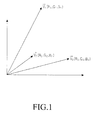
- FIG. 1 is a diagram illustrating an example of MF, VMF, and VDF according to the related art.
- the MF depends on a method of obtaining a mean of pixel values in a local region.
- the MF is a Low Pass Filter (LPF)
- LPF Low Pass Filter
- the median filter is a filter, which is efficient in reducing laplacian noise, which can efficiently reduce pixels in which colors are visually splashed.
- the methods for reducing color noise such as MF, VMF, VDF, or the like, according to the related art, uniformly reduce the color noise to the same degree without accurately considering the correlation between luminance Y of images and chrominance Cb and Cr of images and edge characteristics.
- the present invention has been made to solve the above-mentioned problems occurring in the prior art, and the present invention provides a method and apparatus for reducing color noise capable of keeping a high frequency component necessary for an image such as an edge to vividly output the image by reducing color noise generated by an image sensor by using the correlation between luminance and chrominance and edge characteristics in order to provide a high definition image.
- a method for reducing color noise including calculating a distance weight according to a distance from a central pixel to each pixel of an input image in a mask having a predetermined size; calculating an edge weight depending on a luminance and a chrominance between the central pixel and each pixel; calculating a weight mean of each pixel by using the calculated distance weight and edge weight; and correcting the luminance and the chrominance of each pixel by using the calculated weight mean.
- a device for reducing color noise including a distance weight calculator calculating a distance weight according to a distance from a central pixel to each pixel of an input image in a mask having a predetermined size; an edge weight calculator calculating an edge weight depending on a luminance and a chrominance between the central pixel and each pixel; a weight mean calculator calculating a weight mean of each pixel by using the calculated distance weight and the edge weight; and a color noise reducing unit correcting the luminance and the chrominance of each pixel by using the calculated weight mean.
- an image photographing apparatus including an image photographing unit photographing images and converting them into image signals; an image signal processor processing the images into image signals including luminance and chrominance; a device for reducing color noise correcting luminance and chrominance of each pixel by using a distance weight depending on a distance from a central pixel to each pixel of an input image and an edge weight depending on a difference in luminance and chrominance between the central pixel and each pixel of the image; a display unit outputting an image signal from which color noise is reduced; and a storage unit storing the image signal from which color noise is reduced.
- the present invention reduces the color noise generated by the image sensor using the correlation between luminance and chrominance and the edge characteristics, the high frequency components necessary for images, such as edges, are maintained to vividly represent the detailed portions, as compared to the method of uniformly reducing color noise by the average value in the relationship between the adjacent pixels.
- FIG. 2 is a flow chart showing each process in a method for reducing color noise according to an embodiment of the present invention.
- the method for reducing color noise includes calculating a distance weight in step S21, calculating an edge weight in step S22, calculating a weight mean in step S23, and correcting luminance and chrominance in step S24.
- the method of reducing color noise uses the correlation between the luminance and the chrominance and edge characteristics, thereby making it possible to effectively reduce the color noise generated by an image sensor.
- the distance weight is calculated on the basis of coordinates of a central pixel within a mask having a predetermined size in an image.
- the predetermined size can be a pixel array of 5 x 5, 7 x 7, or the like.
- the distance weight is determined to be inversely proportional to the distance between the coordinates of each pixel to be calculated from the coordinates of the central pixel. Therefore, as the distance between the coordinates of the central pixel and the coordinates of each pixel to be calculated is increased, the distance weight is decreased.
- the distance weight W d (r,c) may be determined to be in inverse proportion to the distance between the coordinates of the central pixel and the coordinates of the pixel to be calculated, that is, between the coordinates of each pixel. Additionally, the relationship between them may be represented in various forms.
- the distance weight is introduced into the method to reduce color noise is to apply differentially the color noise reducing ratio depending on the distance from the central pixel, with respect to any two pixels where the luminance Y and the chrominance Cb and Cr are changed at the same ratio based on the central pixel.
- the edge weight is the difference in size between the luminance and the chrominance of the central pixel and the luminance and the chrominance of each pixel.
- the edge is a portion where the luminance or the chrominance is suddenly changed between adjacent pixels in the mask 3-1, that is, a portion corresponding to a contour of an object (for example, a person, animal, building, or the like) formed in the frame 3 corresponding to a subject.
- an absolute value of the difference in size between the YCbCr components forming the central pixel and each pixel is first calculated. It is assumed that the luminance and the chrominance of the central pixel are Y in (r c ,c c ) and Cb in (r c ,c c ) and Cr in (r c ,c c ), respectively, and the luminance and the chrominance of each pixel are Y in (r,c) and Cb in (r,c) and Cr in (r,c), respectively.
- the absolute values D Y , D Cb , and D Cr of the difference in the luminance and the chrominance between the central pixel and each pixel are represented by the following Equation (3).
- D Y Y in r c ⁇ c c - Y in r ⁇ c
- D Cb Cb in r c ⁇ c c - Cb in r ⁇ c
- D Cr Cr in r c ⁇ c c - Cr in r ⁇ c
- the edge weight W e_Y (r,c) of the luminance Y, the edge weight W e_Cb (r,c) of the chrominance Cb, and the edge weight W e_Cr (r,c) of the chrominance Cr are calculated by using the absolute values D Y , D Cb , and D Cr depending on the difference in size of the calculated YCbCr signal.
- the edge weights W e_Y (r,c), W e_Cb (r,c), and W e_Cr (r,c) are calculated by the following Equation (4) depending on preset threshold values th e_Y , th e_Cb , and th e_Cr .
- Equation (4) if the absolute value D Y is the threshold value th e_Y or less, 0 ⁇ D Y /th e_Y ⁇ 1.
- D Cr is the threshold value th e_Cr or less
- the weight mean of each pixel is calculated by using the calculated distance weight and the edge weight.
- Equation (5) the weight mean is calculated by the above four types and the weights of each edge are changed according to the type used.
- N in R N and C N represents a serial number of each pixel in addition to the central pixel within one mask. For example, when the size of the mask is formed by a 5 x 5 pixel array, there will be 24 pixels other than the central pixel. Equation 5 represents each of 24 pixels to which an integer serial number is attached.
- the four types of weight means can calculate Y wm_y , Y wm_ycbcr , Cb wm_ycbcr , and Cr wm_ycbcr from Equation (5).
- the color noise of the image is reduced by correcting the YCbCr of each pixel using the weight mean calculated at in step S23.
- Equation (6) K', K", and K"' represent any constant. Additionally, relationships in Equation (7) may be derived by modifying Equation (6).
- Equation (7) K"", K""', and K""" represent any constant.
- the YCbCr format is transformed by using an RGB format and the relationship of Equation (7) may be applied to each component in the YCbCr format.
- the relationship of each component is represented by Equation (8).
- Equation (8) K1 and K2 represent any constant.
- the correlation between the YCbCr components of three pixels in Equation (8) is derived under the assumption that the three pixels are in similar regions. However, since the edge is actually present in the image and the pixel of the region having different characteristics is actually present in the image, the relationship of the following Equation (9) may be derived considering edge characteristics.
- Y out - C ⁇ b out Y wm_ycbcr - C ⁇ b wm_ycbcr
- Y out - C ⁇ r out Y wm_ycbcr - C ⁇ r wm_ycbcr
- Equation (9) If Equation (9) is arranged depending on Cb out and Cr out , it becomes Equation (10).
- C ⁇ b out Cb wm_ycbcr - Y wm_ycbcr - Y out
- C ⁇ r out Cr wm_ycbcr - Y wm_ycbcr - Y out
- Equation (10) can be converted to Equation (11).
- C ⁇ b out Cb wm_ycbcr - W cb ⁇ Y wm_ycbcr - Y wm_y
- C ⁇ r out Cr wm_ycbcr - W cr ⁇ Y wm_ycbcr - Y wm_y
- Equation (11) W Cb and W Cr are a preset weight. Cb component and Cr component from which noise is finally reduced by Equation (11) is obtained.
- the method for reducing color noise of an image may be implemented by reflecting the distance weight and the edge weight through steps S21 to S24.
- the present invention provides a method for more effectively reducing color noise of an image than the existing methods using only color information Cb and Cr, thereby making it possible to more efficiently reduce color noise at the time of photographing images under a low luminance environment.
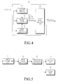
- FIG. 4 is a diagram showing a device for reducing color noise according to an embodiment of the present invention.
- a device for reducing color noise of an image includes a distance weight calculator 41, an edge weight calculator 42, a weight mean calculator 43, and a color noise reducing unit 44.
- the distance weight calculator 41 calculates a distance weight depending on a distance from the central pixel in the mask having a predetermined size to each pixel in the mask in the input image.
- the predetermined size implies a pixel array of 5 x 5, 7 x 7, or the like.
- the distance weight is determined to be in inverse proportion to the distance between the coordinates of each pixel to be calculated from the coordinates of the central pixel.
- the distance weight becomes smaller.
- the distance weight W d (r,c) may be determined to be in inverse proportion to the distance between the coordinates of the central pixel and the coordinates of the pixel to be calculated, that is, between the coordinates of each pixel. Additionally, the relationship between them may be represented by various forms.
- the reason the distance weight is introduced into the method for reducing color noise is to apply the color noise reducing ratio differentially according to the distance from the central pixel, with respect to any two pixels where the luminance Y and the chrominance Cb and Cr are changed at the same ratio based on the central pixel.
- the edge weight calculator 42 calculates the edge weight depending on the difference in size between the luminance and the chrominance of the central pixel and the luminance and the chrominance of every other pixel.
- an absolute value of the difference in size between the YCbCr components forming the central pixel and each pixel is first calculated. It is assumed that the luminance and the chrominance of the central pixel are Y in (r c ,c c ) and Cb in (r c ,c c ) and Cr in (r c ,c c ), respectively, and the luminance and the chrominance of each pixel are Y in (r,c) and Cb in (r,c) and Cr in (r,c), respectively.
- absolute values D Y , D Cb , and D Cr of the difference in the luminance and the chrominance between the central pixel and each pixel were described in Equation (3).
- the edge weight W e_Y (r,c) of luminance Y, the edge weight We_Cb(r,c) of the chrominance Cb, and the edge weight W e_Cr (r,c) of the chrominance Cr are calculated by using the absolute values D Y , D Cb , and D Cr according to the difference in size of the calculated YCbCr signal.
- Equation (4) describes the edge weights W e_Y (r,c), W e_Cb (r,c), and W e_Cr (r,c) calculated depending on the preset threshold values th e_Y , the_Cb, and th e_Cr .
- Equation (4) if absolute value D Y is threshold value th e_Y or less, 0 ⁇ D Y /th e_Y ⁇ 1.
- D Cr is the threshold value th e_Cr or less
- the weight mean calculator 43 calculates the mean weight of each pixel by using the calculated distance weight and the edge weight.
- the weight mean according to the embodiment of the present invention is calculated according to Equation (5).
- the mean weight is calculated by depending on the above four types and the weights of each edge are changed according to whether any one of the four types is used.
- N in R N and the C N represents a serial number of each pixel in addition to the central pixel within one mask. For example, when the size of the mask is formed by a 5 x 5 pixel array, there are 24 pixels other than the central pixel. Equation (5) represents each of 24 pixels to which an integer serial number is attached.
- the four types of mean weights can calculate Y wm_y , Y wm_ycbcr , Cb wm_ycbcr , and Cr wm_ycbcr from Equation (5).
- the color noise reducing unit 44 reduces the color noise of the image by correcting the luminance (Y) and the chrominance (Cb, Cr) of each pixel by using the calculated weight mean.
- each component of YCbCr format is derived from the relationship between each component of the RGB format in a similar region depending on Equations (6) to (8).
- the relationship of each component of YCbCr is derived from Equations (9) and (10) considering the edge characteristics and Equation (11) is finally derived by replacing Y out with Y wm_y and imparting a weight to (Y wm_ycbcr -Y out ) in Equation (10).
- the Cb component and Cr component, from which color noise is reduced, is obtained by using the predetermined weights W Cb and W Cr .
- the apparatus for reducing color noise of an image according to the embodiment of the present invention can more effectively reduce the color noise of the image than the method using only the color information Cb and Cr according to the related art, thereby making it possible to more efficiently reduce the color noise at the time of photographing images under a low luminance environment.
- FIG. 5 is a diagram showing an image photographing apparatus according to an embodiment of the present invention.
- the image photographing apparatus includes an image photographing unit 51, an Image Signal Processor (ISP) 52, a device for reducing color noise 40, a display unit 53, and a storage unit 54.
- ISP Image Signal Processor
- the image photographing unit 51 photographs an image for a subject and converts it into an image signal.
- the image photographing unit includes a lens unit (not shown), an infrared blocking filter unit (not shown), and an image sensor (not shown).
- the lens unit includes a plurality of lenses. Additionally, each of the plurality of lenses has a rotational symmetry with respect to an optical axis and the optical axes of the plurality of lenses are arranged on a single axis.
- the plurality of lenses may be formed in a spherical or an aspherical shape.
- the lens unit may be formed of three lenses made of a plastic material.
- the infrared blocking filter unit serves to block incident light in an infrared band, which the human eye cannot see.
- the image sensor sensitively responds to the incident light of the infrared band (ray having about 750 nm of wavelength) that is not recognized by the human eye. Therefore, since the image photographed by the image sensor would be changed due to the incident light of the infrared band, the infrared blocking filter is used in order to block the incident light of the infrared band.
- the image sensor has a structure where the pixels having the same configuration are disposed in an N x M matrix structure.
- An example of the image sensor may include a CCD, a CMOS, or the like.
- the image sensor is operated under a principle of producing color images by disposing a three primary filter in front of the image sensor and storing information passing through it and then summing it with the stored shading information in the image sensor.
- the ISP 52 is an apparatus for converting the electrical signal converted in the image sensor into the image signal.
- the image signal processor may be implemented in one chip when the image sensor is a CMOS and may be disposed in a chip in a DSP and SoC type. Special functions, such as a handshake preventing function, a low luminance compensating function, or the like may be implemented.
- a device for reducing color noise 40 includes a distance weight calculator, an edge weight calculator, a weight mean calculator, and a color noise reducing unit and includes the same components as the device for reducing color noise in FIG. 4 .
- the display unit 53 displays the image of the subject to be photographed or displays stored images.
- the display unit 53 may be implemented using a Liquid Crystal Display (LCD), a Light Emitting Diode (LED), an Organic Light Emitting Diode (OLED), or the like.
- LCD Liquid Crystal Display
- LED Light Emitting Diode
- OLED Organic Light Emitting Diode
- the storage unit 54 stores the image signal data photographed by the image photographing unit 51. Additionally, the storage unit 54 may store a general program and applications for driving the image photographing apparatus. In particular, the storage unit 54 can store the above equations required to drive the device for reducing color noise included in the image photographing apparatus and store an input/output look-up table corresponding to the equation, such that the output values corresponding to the input values can also refer to the look-up table.
- the image photographing apparatus can more effectively reduce color noise of the image than a method using only the color information Cb and Cr according to the related art, thus making it possible to more efficiently reduce the color noise at the time of photographing images under a low luminance environment.
- Embodiments of the present invention may be implemented in the form of hardware, software, and a combination thereof. Any such software may be stored, for example, in a volatile or non-volatile storage device such as a ROM, a memory such as a RAM, a memory chip, a memory device, or a memory IC, or a recordable optical or magnetic medium such as a CD, a DVD, a magnetic disk, or a magnetic tape, regardless of erasability or re-recordability. It can be also appreciated that the storage device and the storage medium are embodiments of machine-readable devices suitable for storing a program including instructions that are executed by a processor device to thereby implement embodiments of the present invention.
- a volatile or non-volatile storage device such as a ROM, a memory such as a RAM, a memory chip, a memory device, or a memory IC, or a recordable optical or magnetic medium such as a CD, a DVD, a magnetic disk, or a magnetic tape, regardless of eras
- embodiments of the present invention provide a program including codes for implementing a system or method claimed in any claim of the accompanying claims and a machine-readable device for storing such a program. Further, this program may be electronically conveyed through any medium such as a communication signal transferred via a wired or wireless connection, and embodiments of the present invention appropriately include equivalents thereto.
Landscapes
- Engineering & Computer Science (AREA)
- Multimedia (AREA)
- Signal Processing (AREA)
- Physics & Mathematics (AREA)
- General Physics & Mathematics (AREA)
- Theoretical Computer Science (AREA)
- Color Image Communication Systems (AREA)
- Facsimile Image Signal Circuits (AREA)
- Image Processing (AREA)
- Processing Of Color Television Signals (AREA)
- Color Television Image Signal Generators (AREA)
Applications Claiming Priority (1)
| Application Number | Priority Date | Filing Date | Title |
|---|---|---|---|
| KR1020100021218A KR101119268B1 (ko) | 2010-03-10 | 2010-03-10 | 영상의 컬러 잡음 제거 방법 및 장치 |
Publications (3)
| Publication Number | Publication Date |
|---|---|
| EP2365696A2 true EP2365696A2 (fr) | 2011-09-14 |
| EP2365696A3 EP2365696A3 (fr) | 2015-09-09 |
| EP2365696B1 EP2365696B1 (fr) | 2019-10-02 |
Family
ID=43608372
Family Applications (1)
| Application Number | Title | Priority Date | Filing Date |
|---|---|---|---|
| EP11153675.1A Active EP2365696B1 (fr) | 2010-03-10 | 2011-02-08 | Procédé et dispositif pour réduire le bruit de couleur d'une image |
Country Status (4)
| Country | Link |
|---|---|
| US (1) | US8711251B2 (fr) |
| EP (1) | EP2365696B1 (fr) |
| KR (1) | KR101119268B1 (fr) |
| CN (1) | CN102194218B (fr) |
Cited By (1)
| Publication number | Priority date | Publication date | Assignee | Title |
|---|---|---|---|---|
| JP2014216019A (ja) * | 2013-04-26 | 2014-11-17 | 富士通株式会社 | 画像ノイズ低減方法及び画像ノイズ低減装置 |
Families Citing this family (10)
| Publication number | Priority date | Publication date | Assignee | Title |
|---|---|---|---|---|
| KR101361114B1 (ko) * | 2012-07-12 | 2014-02-13 | 매크로영상기술(주) | 디지털 영상을 위한 적응적 잡음 저감 시스템 및 그 방법 |
| JP2014090359A (ja) * | 2012-10-31 | 2014-05-15 | Sony Corp | 画像処理装置、および画像処理方法、並びにプログラム |
| KR102082779B1 (ko) * | 2013-04-16 | 2020-03-02 | 삼성디스플레이 주식회사 | 플렉서블 디스플레이 장치 및 그 제어 방법 |
| US9047665B2 (en) * | 2013-08-21 | 2015-06-02 | Panasonic Intellectual Property Management Co., Ltd. | Image processing apparatus |
| US10382711B2 (en) * | 2014-09-26 | 2019-08-13 | Lg Electronics Inc. | Method and device for processing graph-based signal using geometric primitives |
| US9674466B2 (en) * | 2015-02-26 | 2017-06-06 | Dual Aperture International Co., Ltd. | Hybrid image correction for dual-aperture camera |
| KR102055253B1 (ko) * | 2015-04-28 | 2019-12-13 | 삼성전자주식회사 | 영상 개선 장치 및 영상 개선 방법 |
| US11250769B2 (en) * | 2020-03-31 | 2022-02-15 | Shenzhen China Star Optoelectronics Semiconductor Display Technology Co., Ltd. | Compensation system and compensation method for life attenuation of OLED device |
| JP7604949B2 (ja) * | 2021-03-03 | 2024-12-24 | 富士通株式会社 | 表示制御プログラム、表示制御方法及び表示制御装置 |
| KR20240139314A (ko) * | 2023-03-14 | 2024-09-23 | 주식회사 엘엑스세미콘 | 디스플레이 구동 장치 및 이를 포함하는 디스플레이 장치 |
Family Cites Families (11)
| Publication number | Priority date | Publication date | Assignee | Title |
|---|---|---|---|---|
| JP4269367B2 (ja) | 1997-11-28 | 2009-05-27 | ソニー株式会社 | カメラ信号処理装置及びカメラ信号処理方法 |
| JP4097587B2 (ja) * | 2002-10-16 | 2008-06-11 | 松下電器産業株式会社 | 画像処理装置および画像処理方法 |
| US7292733B2 (en) * | 2002-10-16 | 2007-11-06 | Matsushita Electric Industrial Co., Ltd. | Image processing apparatus and image processing method |
| JP2005109991A (ja) * | 2003-09-30 | 2005-04-21 | Canon Inc | 信号処理方法及び装置、撮像装置 |
| US7945111B2 (en) * | 2004-12-20 | 2011-05-17 | Nikon Corporation | Image processing method for adaptively filtering image data |
| KR100667803B1 (ko) * | 2005-06-21 | 2007-01-11 | 삼성전자주식회사 | 컬러 채널 상호간의 특성을 고려한 컬러 잡음 제거 방법 및장치 |
| JP4977395B2 (ja) * | 2006-04-14 | 2012-07-18 | 富士フイルム株式会社 | 画像処理装置及び方法 |
| KR101340518B1 (ko) * | 2007-08-23 | 2013-12-11 | 삼성전기주식회사 | 영상의 색수차 보정 방법 및 장치 |
| KR101385961B1 (ko) * | 2007-12-21 | 2014-04-16 | 삼성전자주식회사 | 영상신호의 색 노이즈 제거 장치 및 방법 |
| US8135237B2 (en) * | 2008-02-25 | 2012-03-13 | Aptina Imaging Corporation | Apparatuses and methods for noise reduction |
| US8254718B2 (en) * | 2008-05-15 | 2012-08-28 | Microsoft Corporation | Multi-channel edge-aware chrominance noise reduction |
-
2010
- 2010-03-10 KR KR1020100021218A patent/KR101119268B1/ko not_active Expired - Fee Related
-
2011
- 2011-02-08 EP EP11153675.1A patent/EP2365696B1/fr active Active
- 2011-03-10 US US13/045,110 patent/US8711251B2/en not_active Expired - Fee Related
- 2011-03-10 CN CN201110057331.5A patent/CN102194218B/zh not_active Expired - Fee Related
Non-Patent Citations (1)
| Title |
|---|
| None |
Cited By (2)
| Publication number | Priority date | Publication date | Assignee | Title |
|---|---|---|---|---|
| JP2014216019A (ja) * | 2013-04-26 | 2014-11-17 | 富士通株式会社 | 画像ノイズ低減方法及び画像ノイズ低減装置 |
| GB2514895B (en) * | 2013-04-26 | 2020-03-25 | Fujitsu Ltd | A method and an apparatus for reducing image noise |
Also Published As
| Publication number | Publication date |
|---|---|
| KR20110101880A (ko) | 2011-09-16 |
| EP2365696B1 (fr) | 2019-10-02 |
| KR101119268B1 (ko) | 2012-03-20 |
| CN102194218B (zh) | 2016-06-22 |
| US20110221937A1 (en) | 2011-09-15 |
| EP2365696A3 (fr) | 2015-09-09 |
| US8711251B2 (en) | 2014-04-29 |
| CN102194218A (zh) | 2011-09-21 |
Similar Documents
| Publication | Publication Date | Title |
|---|---|---|
| EP2365696B1 (fr) | Procédé et dispositif pour réduire le bruit de couleur d'une image | |
| US20250156996A1 (en) | Systems and Methods for Synthesizing High Resolution Images Using Images Captured by an Array of Independently Controllable Imagers | |
| US8320712B2 (en) | Satellite image fusion method and system | |
| TWI737979B (zh) | 圖像去馬賽克裝置及方法 | |
| CN102844788B (zh) | 图像处理装置及使用该图像处理装置的图像拾取装置 | |
| US8798389B2 (en) | Image processing method, image processing apparatus, and image pickup apparatus for correcting degradation component of image | |
| US8666153B2 (en) | Image input apparatus | |
| US8379976B2 (en) | Image processing apparatus and method and a computer-readable recording medium on which an image processing program is stored | |
| JP6525718B2 (ja) | 画像処理装置、その制御方法、および制御プログラム | |
| US7986352B2 (en) | Image generation system including a plurality of light receiving elements and for correcting image data using a spatial high frequency component, image generation method for correcting image data using a spatial high frequency component, and computer-readable recording medium having a program for performing the same | |
| US7880772B2 (en) | Imaging apparatus and method for approximating color matching functions | |
| US20070139739A1 (en) | Color correction apparatus and method | |
| US20090219417A1 (en) | Image capturing system and computer readable recording medium for recording image processing program | |
| US20100265352A1 (en) | Image processing apparatus, control method therefor, and storage medium | |
| JPWO2011122284A1 (ja) | 画像処理装置、およびそれを用いた撮像装置 | |
| US8085320B1 (en) | Early radial distortion correction | |
| EP3381012B1 (fr) | Procédé et système pour générer une image de sortie à partir d'une pluralité de canaux d'image d'entrée correspondants | |
| US6542187B1 (en) | Correcting for chrominance interpolation artifacts | |
| CN106165398A (zh) | 摄像元件、摄像装置以及图像处理装置 | |
| US20240087086A1 (en) | Image processing method, image processing apparatus, program, trained machine learning model production method, processing apparatus, and image processing system | |
| JP7504629B2 (ja) | 画像処理方法、画像処理装置、画像処理プログラム、および記憶媒体 | |
| KR101230909B1 (ko) | 차량용 광각 영상 처리장치 및 그 방법 | |
| US8068145B1 (en) | Method, systems, and computer program product for demosaicing images | |
| JP2021170197A (ja) | 画像処理方法、画像処理装置、画像処理プログラム、および学習済みモデルの製造方法 | |
| WO2011121761A1 (fr) | Appareil de traitement d'images et appareil de capture d'images le comprenant |
Legal Events
| Date | Code | Title | Description |
|---|---|---|---|
| PUAI | Public reference made under article 153(3) epc to a published international application that has entered the european phase |
Free format text: ORIGINAL CODE: 0009012 |
|
| AK | Designated contracting states |
Kind code of ref document: A2 Designated state(s): AL AT BE BG CH CY CZ DE DK EE ES FI FR GB GR HR HU IE IS IT LI LT LU LV MC MK MT NL NO PL PT RO RS SE SI SK SM TR |
|
| AX | Request for extension of the european patent |
Extension state: BA ME |
|
| RAP1 | Party data changed (applicant data changed or rights of an application transferred) |
Owner name: SAMSUNG ELECTRONICS CO., LTD. |
|
| PUAL | Search report despatched |
Free format text: ORIGINAL CODE: 0009013 |
|
| AK | Designated contracting states |
Kind code of ref document: A3 Designated state(s): AL AT BE BG CH CY CZ DE DK EE ES FI FR GB GR HR HU IE IS IT LI LT LU LV MC MK MT NL NO PL PT RO RS SE SI SK SM TR |
|
| AX | Request for extension of the european patent |
Extension state: BA ME |
|
| RIC1 | Information provided on ipc code assigned before grant |
Ipc: H04N 9/04 20060101AFI20150804BHEP Ipc: H04N 9/64 20060101ALI20150804BHEP Ipc: G06T 5/00 20060101ALI20150804BHEP |
|
| 17P | Request for examination filed |
Effective date: 20160309 |
|
| RBV | Designated contracting states (corrected) |
Designated state(s): AL AT BE BG CH CY CZ DE DK EE ES FI FR GB GR HR HU IE IS IT LI LT LU LV MC MK MT NL NO PL PT RO RS SE SI SK SM TR |
|
| STAA | Information on the status of an ep patent application or granted ep patent |
Free format text: STATUS: EXAMINATION IS IN PROGRESS |
|
| 17Q | First examination report despatched |
Effective date: 20171026 |
|
| RIC1 | Information provided on ipc code assigned before grant |
Ipc: H04N 9/04 20060101AFI20190305BHEP Ipc: G06T 5/00 20060101ALI20190305BHEP Ipc: H04N 9/64 20060101ALI20190305BHEP Ipc: G06T 5/20 20060101ALI20190305BHEP |
|
| GRAP | Despatch of communication of intention to grant a patent |
Free format text: ORIGINAL CODE: EPIDOSNIGR1 |
|
| STAA | Information on the status of an ep patent application or granted ep patent |
Free format text: STATUS: GRANT OF PATENT IS INTENDED |
|
| INTG | Intention to grant announced |
Effective date: 20190417 |
|
| GRAS | Grant fee paid |
Free format text: ORIGINAL CODE: EPIDOSNIGR3 |
|
| GRAA | (expected) grant |
Free format text: ORIGINAL CODE: 0009210 |
|
| STAA | Information on the status of an ep patent application or granted ep patent |
Free format text: STATUS: THE PATENT HAS BEEN GRANTED |
|
| AK | Designated contracting states |
Kind code of ref document: B1 Designated state(s): AL AT BE BG CH CY CZ DE DK EE ES FI FR GB GR HR HU IE IS IT LI LT LU LV MC MK MT NL NO PL PT RO RS SE SI SK SM TR |
|
| REG | Reference to a national code |
Ref country code: GB Ref legal event code: FG4D |
|
| REG | Reference to a national code |
Ref country code: CH Ref legal event code: EP Ref country code: AT Ref legal event code: REF Ref document number: 1187509 Country of ref document: AT Kind code of ref document: T Effective date: 20191015 |
|
| REG | Reference to a national code |
Ref country code: DE Ref legal event code: R096 Ref document number: 602011062409 Country of ref document: DE |
|
| REG | Reference to a national code |
Ref country code: IE Ref legal event code: FG4D |
|
| REG | Reference to a national code |
Ref country code: NL Ref legal event code: MP Effective date: 20191002 |
|
| REG | Reference to a national code |
Ref country code: LT Ref legal event code: MG4D |
|
| REG | Reference to a national code |
Ref country code: AT Ref legal event code: MK05 Ref document number: 1187509 Country of ref document: AT Kind code of ref document: T Effective date: 20191002 |
|
| PG25 | Lapsed in a contracting state [announced via postgrant information from national office to epo] |
Ref country code: SE Free format text: LAPSE BECAUSE OF FAILURE TO SUBMIT A TRANSLATION OF THE DESCRIPTION OR TO PAY THE FEE WITHIN THE PRESCRIBED TIME-LIMIT Effective date: 20191002 Ref country code: LV Free format text: LAPSE BECAUSE OF FAILURE TO SUBMIT A TRANSLATION OF THE DESCRIPTION OR TO PAY THE FEE WITHIN THE PRESCRIBED TIME-LIMIT Effective date: 20191002 Ref country code: AT Free format text: LAPSE BECAUSE OF FAILURE TO SUBMIT A TRANSLATION OF THE DESCRIPTION OR TO PAY THE FEE WITHIN THE PRESCRIBED TIME-LIMIT Effective date: 20191002 Ref country code: PT Free format text: LAPSE BECAUSE OF FAILURE TO SUBMIT A TRANSLATION OF THE DESCRIPTION OR TO PAY THE FEE WITHIN THE PRESCRIBED TIME-LIMIT Effective date: 20200203 Ref country code: BG Free format text: LAPSE BECAUSE OF FAILURE TO SUBMIT A TRANSLATION OF THE DESCRIPTION OR TO PAY THE FEE WITHIN THE PRESCRIBED TIME-LIMIT Effective date: 20200102 Ref country code: FI Free format text: LAPSE BECAUSE OF FAILURE TO SUBMIT A TRANSLATION OF THE DESCRIPTION OR TO PAY THE FEE WITHIN THE PRESCRIBED TIME-LIMIT Effective date: 20191002 Ref country code: GR Free format text: LAPSE BECAUSE OF FAILURE TO SUBMIT A TRANSLATION OF THE DESCRIPTION OR TO PAY THE FEE WITHIN THE PRESCRIBED TIME-LIMIT Effective date: 20200103 Ref country code: NO Free format text: LAPSE BECAUSE OF FAILURE TO SUBMIT A TRANSLATION OF THE DESCRIPTION OR TO PAY THE FEE WITHIN THE PRESCRIBED TIME-LIMIT Effective date: 20200102 Ref country code: PL Free format text: LAPSE BECAUSE OF FAILURE TO SUBMIT A TRANSLATION OF THE DESCRIPTION OR TO PAY THE FEE WITHIN THE PRESCRIBED TIME-LIMIT Effective date: 20191002 Ref country code: NL Free format text: LAPSE BECAUSE OF FAILURE TO SUBMIT A TRANSLATION OF THE DESCRIPTION OR TO PAY THE FEE WITHIN THE PRESCRIBED TIME-LIMIT Effective date: 20191002 Ref country code: LT Free format text: LAPSE BECAUSE OF FAILURE TO SUBMIT A TRANSLATION OF THE DESCRIPTION OR TO PAY THE FEE WITHIN THE PRESCRIBED TIME-LIMIT Effective date: 20191002 Ref country code: ES Free format text: LAPSE BECAUSE OF FAILURE TO SUBMIT A TRANSLATION OF THE DESCRIPTION OR TO PAY THE FEE WITHIN THE PRESCRIBED TIME-LIMIT Effective date: 20191002 |
|
| PGFP | Annual fee paid to national office [announced via postgrant information from national office to epo] |
Ref country code: GB Payment date: 20200123 Year of fee payment: 10 Ref country code: DE Payment date: 20200121 Year of fee payment: 10 |
|
| PG25 | Lapsed in a contracting state [announced via postgrant information from national office to epo] |
Ref country code: HR Free format text: LAPSE BECAUSE OF FAILURE TO SUBMIT A TRANSLATION OF THE DESCRIPTION OR TO PAY THE FEE WITHIN THE PRESCRIBED TIME-LIMIT Effective date: 20191002 Ref country code: IS Free format text: LAPSE BECAUSE OF FAILURE TO SUBMIT A TRANSLATION OF THE DESCRIPTION OR TO PAY THE FEE WITHIN THE PRESCRIBED TIME-LIMIT Effective date: 20200224 Ref country code: CZ Free format text: LAPSE BECAUSE OF FAILURE TO SUBMIT A TRANSLATION OF THE DESCRIPTION OR TO PAY THE FEE WITHIN THE PRESCRIBED TIME-LIMIT Effective date: 20191002 Ref country code: RS Free format text: LAPSE BECAUSE OF FAILURE TO SUBMIT A TRANSLATION OF THE DESCRIPTION OR TO PAY THE FEE WITHIN THE PRESCRIBED TIME-LIMIT Effective date: 20191002 |
|
| PG25 | Lapsed in a contracting state [announced via postgrant information from national office to epo] |
Ref country code: AL Free format text: LAPSE BECAUSE OF FAILURE TO SUBMIT A TRANSLATION OF THE DESCRIPTION OR TO PAY THE FEE WITHIN THE PRESCRIBED TIME-LIMIT Effective date: 20191002 |
|
| PGFP | Annual fee paid to national office [announced via postgrant information from national office to epo] |
Ref country code: FR Payment date: 20200123 Year of fee payment: 10 |
|
| REG | Reference to a national code |
Ref country code: DE Ref legal event code: R097 Ref document number: 602011062409 Country of ref document: DE |
|
| PG2D | Information on lapse in contracting state deleted |
Ref country code: IS |
|
| PG25 | Lapsed in a contracting state [announced via postgrant information from national office to epo] |
Ref country code: EE Free format text: LAPSE BECAUSE OF FAILURE TO SUBMIT A TRANSLATION OF THE DESCRIPTION OR TO PAY THE FEE WITHIN THE PRESCRIBED TIME-LIMIT Effective date: 20191002 Ref country code: RO Free format text: LAPSE BECAUSE OF FAILURE TO SUBMIT A TRANSLATION OF THE DESCRIPTION OR TO PAY THE FEE WITHIN THE PRESCRIBED TIME-LIMIT Effective date: 20191002 Ref country code: DK Free format text: LAPSE BECAUSE OF FAILURE TO SUBMIT A TRANSLATION OF THE DESCRIPTION OR TO PAY THE FEE WITHIN THE PRESCRIBED TIME-LIMIT Effective date: 20191002 Ref country code: IS Free format text: LAPSE BECAUSE OF FAILURE TO SUBMIT A TRANSLATION OF THE DESCRIPTION OR TO PAY THE FEE WITHIN THE PRESCRIBED TIME-LIMIT Effective date: 20200202 |
|
| PLBE | No opposition filed within time limit |
Free format text: ORIGINAL CODE: 0009261 |
|
| STAA | Information on the status of an ep patent application or granted ep patent |
Free format text: STATUS: NO OPPOSITION FILED WITHIN TIME LIMIT |
|
| PG25 | Lapsed in a contracting state [announced via postgrant information from national office to epo] |
Ref country code: SM Free format text: LAPSE BECAUSE OF FAILURE TO SUBMIT A TRANSLATION OF THE DESCRIPTION OR TO PAY THE FEE WITHIN THE PRESCRIBED TIME-LIMIT Effective date: 20191002 Ref country code: IT Free format text: LAPSE BECAUSE OF FAILURE TO SUBMIT A TRANSLATION OF THE DESCRIPTION OR TO PAY THE FEE WITHIN THE PRESCRIBED TIME-LIMIT Effective date: 20191002 Ref country code: SK Free format text: LAPSE BECAUSE OF FAILURE TO SUBMIT A TRANSLATION OF THE DESCRIPTION OR TO PAY THE FEE WITHIN THE PRESCRIBED TIME-LIMIT Effective date: 20191002 |
|
| 26N | No opposition filed |
Effective date: 20200703 |
|
| REG | Reference to a national code |
Ref country code: CH Ref legal event code: PL |
|
| REG | Reference to a national code |
Ref country code: BE Ref legal event code: MM Effective date: 20200229 |
|
| PG25 | Lapsed in a contracting state [announced via postgrant information from national office to epo] |
Ref country code: LU Free format text: LAPSE BECAUSE OF NON-PAYMENT OF DUE FEES Effective date: 20200208 Ref country code: MC Free format text: LAPSE BECAUSE OF FAILURE TO SUBMIT A TRANSLATION OF THE DESCRIPTION OR TO PAY THE FEE WITHIN THE PRESCRIBED TIME-LIMIT Effective date: 20191002 |
|
| PG25 | Lapsed in a contracting state [announced via postgrant information from national office to epo] |
Ref country code: SI Free format text: LAPSE BECAUSE OF FAILURE TO SUBMIT A TRANSLATION OF THE DESCRIPTION OR TO PAY THE FEE WITHIN THE PRESCRIBED TIME-LIMIT Effective date: 20191002 Ref country code: LI Free format text: LAPSE BECAUSE OF NON-PAYMENT OF DUE FEES Effective date: 20200229 Ref country code: CH Free format text: LAPSE BECAUSE OF NON-PAYMENT OF DUE FEES Effective date: 20200229 |
|
| PG25 | Lapsed in a contracting state [announced via postgrant information from national office to epo] |
Ref country code: IE Free format text: LAPSE BECAUSE OF NON-PAYMENT OF DUE FEES Effective date: 20200208 |
|
| PG25 | Lapsed in a contracting state [announced via postgrant information from national office to epo] |
Ref country code: BE Free format text: LAPSE BECAUSE OF NON-PAYMENT OF DUE FEES Effective date: 20200229 |
|
| REG | Reference to a national code |
Ref country code: DE Ref legal event code: R119 Ref document number: 602011062409 Country of ref document: DE |
|
| GBPC | Gb: european patent ceased through non-payment of renewal fee |
Effective date: 20210208 |
|
| PG25 | Lapsed in a contracting state [announced via postgrant information from national office to epo] |
Ref country code: DE Free format text: LAPSE BECAUSE OF NON-PAYMENT OF DUE FEES Effective date: 20210901 Ref country code: GB Free format text: LAPSE BECAUSE OF NON-PAYMENT OF DUE FEES Effective date: 20210208 Ref country code: FR Free format text: LAPSE BECAUSE OF NON-PAYMENT OF DUE FEES Effective date: 20210228 |
|
| PG25 | Lapsed in a contracting state [announced via postgrant information from national office to epo] |
Ref country code: TR Free format text: LAPSE BECAUSE OF FAILURE TO SUBMIT A TRANSLATION OF THE DESCRIPTION OR TO PAY THE FEE WITHIN THE PRESCRIBED TIME-LIMIT Effective date: 20191002 Ref country code: MT Free format text: LAPSE BECAUSE OF FAILURE TO SUBMIT A TRANSLATION OF THE DESCRIPTION OR TO PAY THE FEE WITHIN THE PRESCRIBED TIME-LIMIT Effective date: 20191002 Ref country code: CY Free format text: LAPSE BECAUSE OF FAILURE TO SUBMIT A TRANSLATION OF THE DESCRIPTION OR TO PAY THE FEE WITHIN THE PRESCRIBED TIME-LIMIT Effective date: 20191002 |
|
| PG25 | Lapsed in a contracting state [announced via postgrant information from national office to epo] |
Ref country code: MK Free format text: LAPSE BECAUSE OF FAILURE TO SUBMIT A TRANSLATION OF THE DESCRIPTION OR TO PAY THE FEE WITHIN THE PRESCRIBED TIME-LIMIT Effective date: 20191002 |