EP2365738A1 - Circuit haute tension pour la stimulation électrique - Google Patents
Circuit haute tension pour la stimulation électrique Download PDFInfo
- Publication number
- EP2365738A1 EP2365738A1 EP10156155A EP10156155A EP2365738A1 EP 2365738 A1 EP2365738 A1 EP 2365738A1 EP 10156155 A EP10156155 A EP 10156155A EP 10156155 A EP10156155 A EP 10156155A EP 2365738 A1 EP2365738 A1 EP 2365738A1
- Authority
- EP
- European Patent Office
- Prior art keywords
- circuit
- stimulus
- current
- converter
- animal
- Prior art date
- Legal status (The legal status is an assumption and is not a legal conclusion. Google has not performed a legal analysis and makes no representation as to the accuracy of the status listed.)
- Granted
Links
Images

Classifications
-
- H—ELECTRICITY
- H05—ELECTRIC TECHNIQUES NOT OTHERWISE PROVIDED FOR
- H05C—ELECTRIC CIRCUITS OR APPARATUS SPECIALLY DESIGNED FOR USE IN EQUIPMENT FOR KILLING, STUNNING, OR GUIDING LIVING BEINGS
- H05C1/00—Circuits or apparatus for generating electric shock effects
- H05C1/04—Circuits or apparatus for generating electric shock effects providing pulse voltages
-
- A—HUMAN NECESSITIES
- A01—AGRICULTURE; FORESTRY; ANIMAL HUSBANDRY; HUNTING; TRAPPING; FISHING
- A01K—ANIMAL HUSBANDRY; AVICULTURE; APICULTURE; PISCICULTURE; FISHING; REARING OR BREEDING ANIMALS, NOT OTHERWISE PROVIDED FOR; NEW BREEDS OF ANIMALS
- A01K15/00—Devices for taming animals, e.g. nose-rings or hobbles; Devices for overturning animals in general; Training or exercising equipment; Covering boxes
- A01K15/02—Training or exercising equipment, e.g. mazes or labyrinths for animals ; Electric shock devices; Toys specially adapted for animals
- A01K15/021—Electronic training devices specially adapted for dogs or cats
-
- H—ELECTRICITY
- H05—ELECTRIC TECHNIQUES NOT OTHERWISE PROVIDED FOR
- H05C—ELECTRIC CIRCUITS OR APPARATUS SPECIALLY DESIGNED FOR USE IN EQUIPMENT FOR KILLING, STUNNING, OR GUIDING LIVING BEINGS
- H05C3/00—Other circuits or apparatus
Definitions
- the present invention relates to a module circuit for controlling an electric stimulus applied to an animal.
- the stimulus is usually generated by a means such as a collar bearing electrodes and attached to the animal's neck.
- the collar is typically remote-controlled by radio-frequency means.
- the intensity of the stimulus through the skin of the animal is preferably variable in order to train the animal.
- Dog handlers often use electrical collars in order to keep control of their dog.
- FIG.1 shows a typical module that generates the electrical stimulus through electrodes EP1 and EP2.
- the circuit 1 depicted in FIG.1 is powered by a low voltage battery 3, typically a 3V-battery, and works in two phases:
- Typical repetition frequencies are of the order of 200Hz.
- Document EP 1 968 359 A1 discloses a remote receiving circuit and a method for verifying the impedance of electrodes and for controlling the intensity of an electric stimulus.
- the circuit includes an electronic switch powered by a battery in series on a primary of a high-voltage transformer and whose on/off state can be modified by control pulses to create a source of alternating current to supply the primary of the transformer.
- the circuit further includes a first electrode and a second electrode configured to be in contact with the animal and connected to the respective ends of a secondary of the transformer, and a device for measuring the peak intensity of a stimulus current applied by the electrodes to the animal's body.
- the circuit further comprises means to adjust the generation of control pulses to the measurement of the peak current.
- the present invention aims at circumventing the drawbacks of prior art.
- the invention aims to provide a device of reduced size for controlling an electric stimulus applied to an animal.
- the invention intends also to provide a device suitable to control the shape and the intensity of the stimulus current.
- the invention additionally aims at using the electrodes for other functions such as battery charging.
- Another aim of the invention is to provide a device as above mith multiple electrodes.
- the invention also aims at providing a training collar with means for an easy and/or a high-level parameter setting.
- a first object of the present invention is related to a remote-receiving circuit for providing and controlling an electric stimulus applied to an animal, the circuit comprising :
- preferred embodiments of the remote-receiving circuit according to the invention include one or an appropriate combination of the following characteristics :
- Another object of the invention relates to a device for remotely providing and controlling an electric stimulus applied to an animal, the device comprising :
- FIG.1 shows a typical prior art electronic circuit for the generation of an electrical stimulus.
- FIG.2 shows a general block diagram for the circuit of the present invention.
- FIG.3 shows a preferred embodiment corresponding to the block diagram of FIG.2
- FIG.4 depicts the circuit of FIG.3 with an added diode allowing battery charging.
- FIG.5 shows a variation of the block diagram of FIG.2 with the current limiting circuit connected in an alternative way.
- FIG.6 shows a block diagram as in FIG.5 but having three electrodes instead of one.
- the originality of the present invention lies in the idea of storing the stimulus energy in a capacitor instead of in a transformer and in the addition of a simple high voltage current limiting circuit to control the stimulus.
- the present invention allows a tight control of the current meaning that the previous invention of EP 1 968 359 A1 is still fully applicable.
- the present invention thus proposes to store the energy of the stimulus pulse in a capacitor 8 (called C2) instead of a transformer (see FIG.2 ).
- a 4,7nF / 1000V capacitor can store up to 2.35mJ but has dimensions of only 4.5mm x 2mm x 2mm (to be compared with 20mm x 15mm x 15mm as above).
- a classical isolated DC/DC converter 4 is proposed.
- a flyback converter can be used as a preferred embodiment of a DC/DC converter but other topologies are also possible and would yield the same result.
- the DC/DC converter 4 In order to be able to sustain the typical 200 Hz stimulus pulse frequency, the DC/DC converter 4 has to be able to charge the capacitor 8 (C2) in less than 5 ms, let us consider 4ms.
- the transformer operation at high frequency has another advantage.
- the primary current pulse can be filtered using a very small ceramic capacitor instead of a large tantalum capacitor as in the prior art.
- the present invention additionally proposes to insert a high voltage current limiting circuit 9.
- the current limiting circuit 9 can be built with classical transistors (MOSFET or BJT). It should be noted that the current limiting circuit should be designed to limit the current to 0 during the charge phase of the capacitor. This allows the high frequency transformer to charge capacitor 8 (C2) very quickly because there is then no load on the converter 4.
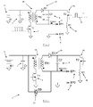
- FIG.3 shows a typical embodiment according to the block diagram presented in FIG.2 .
- the isolated DC/DC converter 4 is made of the input decoupling capacitor 7 (C1), the main switcher 2 (T1), the isolation transformer 4A (TR1), the rectifier 10 (D1) and the output decoupling and storage capacitor 8 (C2). It should be noted that C1 and TR1 are smaller (by one or two orders of magnitude) than C1 and TR1 of the above-mentioned prior art. Even if the presented invention needs more components than the prior art (D1, C2, T2 and R1), these components are very small and the overall size of the presented invention is clearly smaller than the overall size of a prior art circuit.
- the stimulus energy is stored in C2.
- R1 is a simple resistor but it can be advantageously replaced by a more sophisticated circuit that allows peak current measurement, for example the dedicated circuit portion as described in EP 1 968 359 A1 .
- transistors T1 and T2 are MOSFET transistors but these can be replaced by other transistor technologies.
- the pulse train controlling T1 is a high frequency pulse train that is different from that of the prior art.
- the effective stimulus control is performed with the gate voltage applied to T2.
- Equation (1) shows that I stimulus is perfectly controlled with Vg.
- the duration, the peak amplitude and the shape of I stimulus are tightly controlled with Vg. For example, it is possible to generate high and narrow or low and wide stimulus pulses. This was obviously not possible in prior art.
- Diode 11 does not affect the normal operation of the circuit because it is always reverse polarized. However, when T1 and T2 are maintained in the off state, applying a positive voltage between EP1(+) and EP2(-) creates a current through D3 that is suitable to charge battery 3 (B1) .
- circuit of FIG.4 has an additional interesting property. If the voltage source applied to electrodes EP1 and EP2 for battery charging is wrongly connected (reverse polarity), diodes D1 and D3 are reverse polarized, no current flows through the electrodes and the circuit of FIG.4 cannot be damaged. This is a "natural" reverse polarity protection.
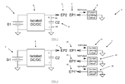
- the current limiting circuit is connected to the positive side 8A of C2. It is however not mandatory to do so because the only requirement for the current limiting circuit 9 is to be in series with C2. Connecting the current limiting circuit to the negative side 8B of C2 yields the circuit of FIG.5 below.
- the isolated DC / DC converter and the current limiting circuit of the invention in this embodiment can be implemented in the same way the block diagram of FIG.2 has been implemented in the circuit of FIG.3 .
- FIG.5 does not allow the battery to be charged using EP1 and EP2.
- connecting the current limiting circuit in that way allows several current limiting circuits to be implemented as shown in the next section ( FIG.6 ).
- the present invention allows to generate the stimulus in different positions of the device on the skin of the animal by simply using multiple electrodes 15, 25, 35 coupled with corresponding current limiting circuits 19, 29, 39, respectively.
- the main difference with the prior art is that adding electrodes only requires additional current limiting circuits but no additional transformer.
- FIG.6 illustrates a manner to generate the stimulus through three different electrodes 15, 25, 35 with only one transformer 4A.
- the size of the circuit is therefore kept very small in comparison to the prior art that would instead require three transformers.
- the three current limiting circuits 19, 29, 39 can be controlled individually. This type of circuit allows an enormous number of ways to generate various stimuli.
- the present invention allows a high degree of control of the shape of the stimulus current. That means that it is possible to define a lot of different stimulation shapes with a lot of different parameters. In the context of dog education, this allows the handler to adapt the stimulus current to his dogs and to his dressage methods.
- PC-like device for example a PC, a laptop, a PDA, a Netbook, an i-phone, etc.
- the communication channel between the PC-like device and the collar to be parameterized can be made with a protocol translation device (USB to radio-frequency for example).
- the handler can also change the way the stimulations are distributed. For example, he can decrease the amplitude of the lowest stimulation (to start with a lower stimulation) or increase the amplitude of the highest stimulation.
- the invention allows a late configuration of the collar by specialists.
- the collar is initially manufactured with default stimulations parameters (restricted to lower levels) but higher levels are accessible to advised persons like a veterinary, a professional in dog training, etc.
- the advantage is that the latter only has to manufacture one product that can serve both usages (consumer and professional), while preserving the animal welfare in all cases.
Landscapes
- Life Sciences & Earth Sciences (AREA)
- Insects & Arthropods (AREA)
- Environmental Sciences (AREA)
- Health & Medical Sciences (AREA)
- General Health & Medical Sciences (AREA)
- Physical Education & Sports Medicine (AREA)
- Animal Behavior & Ethology (AREA)
- Zoology (AREA)
- Animal Husbandry (AREA)
- Biodiversity & Conservation Biology (AREA)
- Electrotherapy Devices (AREA)
Priority Applications (3)
| Application Number | Priority Date | Filing Date | Title |
|---|---|---|---|
| EP10156155.3A EP2365738B1 (fr) | 2010-03-11 | 2010-03-11 | Circuit haute tension pour la stimulation électrique |
| US13/044,114 US8711544B2 (en) | 2010-03-11 | 2011-03-09 | High voltage circuit for electrical stimulation |
| CA2733740A CA2733740A1 (fr) | 2010-03-11 | 2011-03-10 | Circuit haute tension pour stimulation electrique |
Applications Claiming Priority (1)
| Application Number | Priority Date | Filing Date | Title |
|---|---|---|---|
| EP10156155.3A EP2365738B1 (fr) | 2010-03-11 | 2010-03-11 | Circuit haute tension pour la stimulation électrique |
Publications (2)
| Publication Number | Publication Date |
|---|---|
| EP2365738A1 true EP2365738A1 (fr) | 2011-09-14 |
| EP2365738B1 EP2365738B1 (fr) | 2016-07-13 |
Family
ID=42270060
Family Applications (1)
| Application Number | Title | Priority Date | Filing Date |
|---|---|---|---|
| EP10156155.3A Active EP2365738B1 (fr) | 2010-03-11 | 2010-03-11 | Circuit haute tension pour la stimulation électrique |
Country Status (3)
| Country | Link |
|---|---|
| US (1) | US8711544B2 (fr) |
| EP (1) | EP2365738B1 (fr) |
| CA (1) | CA2733740A1 (fr) |
Cited By (2)
| Publication number | Priority date | Publication date | Assignee | Title |
|---|---|---|---|---|
| WO2020051775A1 (fr) * | 2018-09-11 | 2020-03-19 | Oppo广东移动通信有限公司 | Dispositif de fourniture d'alimentation électrique et procédé de commande de charge |
| CN112491124A (zh) * | 2020-10-19 | 2021-03-12 | 安克创新科技股份有限公司 | 一种关于充电器减小体积和提高效率的电路和方法 |
Families Citing this family (5)
| Publication number | Priority date | Publication date | Assignee | Title |
|---|---|---|---|---|
| EP2365738B1 (fr) * | 2010-03-11 | 2016-07-13 | Nouveaux établissements Charles MARTIN S.A: | Circuit haute tension pour la stimulation électrique |
| CN103796406B (zh) * | 2014-01-06 | 2015-09-16 | 南京农业大学 | 一种家禽电麻机调频调压方法 |
| US10451386B2 (en) * | 2016-08-24 | 2019-10-22 | Axon Enterprise, Inc. | Systems and methods for calibrating a conducted electrical weapon |
| EP3723476B1 (fr) * | 2017-12-12 | 2024-04-17 | Radio Systems Corporation | Procédé et appareil pour appliquer, surveiller et ajuster un stimulus à un animal de compagnie |
| US12349660B2 (en) | 2022-11-11 | 2025-07-08 | Radio Systems Corporation | Electrical stimulus device, such as an animal collar, and variable pulse stimulation circuit |
Citations (2)
| Publication number | Priority date | Publication date | Assignee | Title |
|---|---|---|---|---|
| GB2000919A (en) * | 1977-06-29 | 1979-01-17 | Reofon As | Apparatus for generating electric shock pulses |
| EP1968359A1 (fr) | 2007-03-07 | 2008-09-10 | Martin, Charles | Circuit et méthode de vérification de l'impédance d'électrodes et de contrôle de l'intensité d'un stimulus électrique |
Family Cites Families (21)
| Publication number | Priority date | Publication date | Assignee | Title |
|---|---|---|---|---|
| US4618919A (en) * | 1984-10-04 | 1986-10-21 | Sperry Corporation | Topology for miniature power supply with low voltage and low ripple requirements |
| US4667431A (en) * | 1986-02-20 | 1987-05-26 | Mendicino Lyle J | Shark prod |
| JP2520609B2 (ja) * | 1986-09-06 | 1996-07-31 | ファナック 株式会社 | ワイヤ放電加工方法 |
| CA1297937C (fr) * | 1987-02-17 | 1992-03-24 | Paul Podsiadly | Appareil servant a retirer des vers de terre hors de la terre a l'aide de pulsations electriques et methode connexe |
| US4802482A (en) * | 1987-09-21 | 1989-02-07 | Tri-Tronics, Inc. | Method and apparatus for remote control of animal training stimulus |
| US4997418A (en) * | 1988-04-21 | 1991-03-05 | C. P. Chambers | Epidermal iontophoresis device |
| JP2807388B2 (ja) * | 1993-03-19 | 1998-10-08 | 株式会社東芝 | フォトカプラ装置 |
| US5962806A (en) * | 1996-11-12 | 1999-10-05 | Jaycor | Non-lethal projectile for delivering an electric shock to a living target |
| US5892389A (en) * | 1997-06-03 | 1999-04-06 | Motorola, Inc. | Method and circuit for current limiting of DC-DC regulators |
| US6222149B1 (en) * | 1998-06-10 | 2001-04-24 | Sodick Co., Ltd. | Power supply device for electric discharge machining apparatus |
| US6404613B1 (en) * | 2000-01-15 | 2002-06-11 | Pulse-Wave Protective Devices International, Inc. | Animal stun gun |
| US20050000469A1 (en) * | 2003-06-17 | 2005-01-06 | Petrak, Llc | Programming fixture for a virtual fencing system |
| US7602597B2 (en) * | 2003-10-07 | 2009-10-13 | Taser International, Inc. | Systems and methods for immobilization using charge delivery |
| CN1306554C (zh) * | 2004-04-20 | 2007-03-21 | 陈宗烈 | 无灯丝热阴极荧光灯 |
| JP4912577B2 (ja) * | 2004-09-01 | 2012-04-11 | 本田技研工業株式会社 | 2足歩行ロボットの充電システム |
| US7559291B2 (en) * | 2006-03-24 | 2009-07-14 | Innotek, Inc. | Method and apparatus for adjusting the correction level of an animal training receiver |
| US8660660B2 (en) * | 2006-11-14 | 2014-02-25 | Second Sight Medical Products, Inc. | Power scheme for implant stimulators on the human or animal body |
| TW200938090A (en) * | 2008-03-06 | 2009-09-16 | Univ Chang Gung | Multi-channel uniform-current stunner |
| AU2009296712A1 (en) * | 2008-09-23 | 2010-04-01 | Aegis Industries, Inc. | Stun device testing apparatus and methods |
| EP2365738B1 (fr) * | 2010-03-11 | 2016-07-13 | Nouveaux établissements Charles MARTIN S.A: | Circuit haute tension pour la stimulation électrique |
| TWI413559B (zh) * | 2010-12-17 | 2013-11-01 | Ind Tech Res Inst | 自調式放電加工節能電源裝置及其方法 |
-
2010
- 2010-03-11 EP EP10156155.3A patent/EP2365738B1/fr active Active
-
2011
- 2011-03-09 US US13/044,114 patent/US8711544B2/en active Active
- 2011-03-10 CA CA2733740A patent/CA2733740A1/fr not_active Abandoned
Patent Citations (2)
| Publication number | Priority date | Publication date | Assignee | Title |
|---|---|---|---|---|
| GB2000919A (en) * | 1977-06-29 | 1979-01-17 | Reofon As | Apparatus for generating electric shock pulses |
| EP1968359A1 (fr) | 2007-03-07 | 2008-09-10 | Martin, Charles | Circuit et méthode de vérification de l'impédance d'électrodes et de contrôle de l'intensité d'un stimulus électrique |
Cited By (2)
| Publication number | Priority date | Publication date | Assignee | Title |
|---|---|---|---|---|
| WO2020051775A1 (fr) * | 2018-09-11 | 2020-03-19 | Oppo广东移动通信有限公司 | Dispositif de fourniture d'alimentation électrique et procédé de commande de charge |
| CN112491124A (zh) * | 2020-10-19 | 2021-03-12 | 安克创新科技股份有限公司 | 一种关于充电器减小体积和提高效率的电路和方法 |
Also Published As
| Publication number | Publication date |
|---|---|
| US20110220034A1 (en) | 2011-09-15 |
| EP2365738B1 (fr) | 2016-07-13 |
| CA2733740A1 (fr) | 2011-09-11 |
| US8711544B2 (en) | 2014-04-29 |
Similar Documents
| Publication | Publication Date | Title |
|---|---|---|
| EP2365738B1 (fr) | Circuit haute tension pour la stimulation électrique | |
| US9333356B2 (en) | Systems and methods that provide an electrical waveform for neural stimulation or nerve block | |
| EP3008803B1 (fr) | Procede de chargement et appareil manuel pour petit appareil électrique mobile | |
| US9755530B2 (en) | Power converter with synchronous control function and control method thereof | |
| US10498171B2 (en) | Wireless power receiver voltage control enabling simultaneous communications to transmitter in over-voltage state | |
| CN107026573B (zh) | 用于同步整流的自适应关断触发消隐 | |
| DE112015006497T5 (de) | Senderseitige steuerung eines drahtlosleistungsübertragungssystems ohne verwendung von transformatorkopplungsinformationen oder drahtlosrückkopplung | |
| US20080216766A1 (en) | Circuit and method for checking the impedance of electrodes and for controlling the intensity of an electric stimulus | |
| GB2052116A (en) | Micropower systems | |
| EP0384680B1 (fr) | Circuit à commutation | |
| Zan et al. | Wireless power transfer for implantable medical devices using piecewise resonance to achieve high peak-to-average power ratio | |
| US4890616A (en) | Energy saving technique for battery powered inductor | |
| US10236777B2 (en) | Magnetically isolated feedback circuits and regulated power supplies incorporating the same | |
| AU2008203367A1 (en) | Stock Prodder | |
| JP2015202030A (ja) | 非接触給電装置及び非接触給電システム | |
| WO1993022825A1 (fr) | Circuit efficace de commande a transistors pour des circuits convertisseurs de courant electrique et similaire | |
| CN102439834A (zh) | 使用多负载并联磁路中的共享磁通量的电磁装置及其操作方法 | |
| US20180351542A1 (en) | Biasing circuit for switch | |
| CN107947776B (zh) | 一种隔离的开关管驱动电路 | |
| JP2000295783A (ja) | 充電装置の電源回路 | |
| Jiang et al. | A low switching frequency ac-dc boost converter for wireless powered miniaturized implants | |
| EP3160028A1 (fr) | Convertisseur electronique et procede associe de fonctionnement d'un convertisseur electronique | |
| Zou et al. | Dynamic power control circuit for implantable biomedical devices | |
| DE112021005762T5 (de) | Halbleiterrelaisvorrichtung | |
| Tamtrakarn | A 115V bi-phasic pulse electrical muscle stimulator by using inductor-sharing dual-output boost converter with supply-stepping switch driver |
Legal Events
| Date | Code | Title | Description |
|---|---|---|---|
| PUAI | Public reference made under article 153(3) epc to a published international application that has entered the european phase |
Free format text: ORIGINAL CODE: 0009012 |
|
| AK | Designated contracting states |
Kind code of ref document: A1 Designated state(s): AT BE BG CH CY CZ DE DK EE ES FI FR GB GR HR HU IE IS IT LI LT LU LV MC MK MT NL NO PL PT RO SE SI SK SM TR |
|
| AX | Request for extension of the european patent |
Extension state: AL BA ME RS |
|
| 17P | Request for examination filed |
Effective date: 20120313 |
|
| 17Q | First examination report despatched |
Effective date: 20140403 |
|
| GRAP | Despatch of communication of intention to grant a patent |
Free format text: ORIGINAL CODE: EPIDOSNIGR1 |
|
| INTG | Intention to grant announced |
Effective date: 20160208 |
|
| GRAS | Grant fee paid |
Free format text: ORIGINAL CODE: EPIDOSNIGR3 |
|
| GRAA | (expected) grant |
Free format text: ORIGINAL CODE: 0009210 |
|
| AK | Designated contracting states |
Kind code of ref document: B1 Designated state(s): AT BE BG CH CY CZ DE DK EE ES FI FR GB GR HR HU IE IS IT LI LT LU LV MC MK MT NL NO PL PT RO SE SI SK SM TR |
|
| REG | Reference to a national code |
Ref country code: GB Ref legal event code: FG4D |
|
| REG | Reference to a national code |
Ref country code: AT Ref legal event code: REF Ref document number: 813186 Country of ref document: AT Kind code of ref document: T Effective date: 20160715 Ref country code: CH Ref legal event code: EP |
|
| REG | Reference to a national code |
Ref country code: IE Ref legal event code: FG4D |
|
| REG | Reference to a national code |
Ref country code: DE Ref legal event code: R096 Ref document number: 602010034608 Country of ref document: DE |
|
| REG | Reference to a national code |
Ref country code: LT Ref legal event code: MG4D |
|
| REG | Reference to a national code |
Ref country code: NL Ref legal event code: MP Effective date: 20160713 |
|
| REG | Reference to a national code |
Ref country code: AT Ref legal event code: MK05 Ref document number: 813186 Country of ref document: AT Kind code of ref document: T Effective date: 20160713 |
|
| PG25 | Lapsed in a contracting state [announced via postgrant information from national office to epo] |
Ref country code: FI Free format text: LAPSE BECAUSE OF FAILURE TO SUBMIT A TRANSLATION OF THE DESCRIPTION OR TO PAY THE FEE WITHIN THE PRESCRIBED TIME-LIMIT Effective date: 20160713 Ref country code: LT Free format text: LAPSE BECAUSE OF FAILURE TO SUBMIT A TRANSLATION OF THE DESCRIPTION OR TO PAY THE FEE WITHIN THE PRESCRIBED TIME-LIMIT Effective date: 20160713 Ref country code: HR Free format text: LAPSE BECAUSE OF FAILURE TO SUBMIT A TRANSLATION OF THE DESCRIPTION OR TO PAY THE FEE WITHIN THE PRESCRIBED TIME-LIMIT Effective date: 20160713 Ref country code: IT Free format text: LAPSE BECAUSE OF FAILURE TO SUBMIT A TRANSLATION OF THE DESCRIPTION OR TO PAY THE FEE WITHIN THE PRESCRIBED TIME-LIMIT Effective date: 20160713 Ref country code: NO Free format text: LAPSE BECAUSE OF FAILURE TO SUBMIT A TRANSLATION OF THE DESCRIPTION OR TO PAY THE FEE WITHIN THE PRESCRIBED TIME-LIMIT Effective date: 20161013 Ref country code: IS Free format text: LAPSE BECAUSE OF FAILURE TO SUBMIT A TRANSLATION OF THE DESCRIPTION OR TO PAY THE FEE WITHIN THE PRESCRIBED TIME-LIMIT Effective date: 20161113 Ref country code: NL Free format text: LAPSE BECAUSE OF FAILURE TO SUBMIT A TRANSLATION OF THE DESCRIPTION OR TO PAY THE FEE WITHIN THE PRESCRIBED TIME-LIMIT Effective date: 20160713 |
|
| PG25 | Lapsed in a contracting state [announced via postgrant information from national office to epo] |
Ref country code: PT Free format text: LAPSE BECAUSE OF FAILURE TO SUBMIT A TRANSLATION OF THE DESCRIPTION OR TO PAY THE FEE WITHIN THE PRESCRIBED TIME-LIMIT Effective date: 20161114 Ref country code: AT Free format text: LAPSE BECAUSE OF FAILURE TO SUBMIT A TRANSLATION OF THE DESCRIPTION OR TO PAY THE FEE WITHIN THE PRESCRIBED TIME-LIMIT Effective date: 20160713 Ref country code: PL Free format text: LAPSE BECAUSE OF FAILURE TO SUBMIT A TRANSLATION OF THE DESCRIPTION OR TO PAY THE FEE WITHIN THE PRESCRIBED TIME-LIMIT Effective date: 20160713 Ref country code: GR Free format text: LAPSE BECAUSE OF FAILURE TO SUBMIT A TRANSLATION OF THE DESCRIPTION OR TO PAY THE FEE WITHIN THE PRESCRIBED TIME-LIMIT Effective date: 20161014 Ref country code: SE Free format text: LAPSE BECAUSE OF FAILURE TO SUBMIT A TRANSLATION OF THE DESCRIPTION OR TO PAY THE FEE WITHIN THE PRESCRIBED TIME-LIMIT Effective date: 20160713 Ref country code: ES Free format text: LAPSE BECAUSE OF FAILURE TO SUBMIT A TRANSLATION OF THE DESCRIPTION OR TO PAY THE FEE WITHIN THE PRESCRIBED TIME-LIMIT Effective date: 20160713 Ref country code: LV Free format text: LAPSE BECAUSE OF FAILURE TO SUBMIT A TRANSLATION OF THE DESCRIPTION OR TO PAY THE FEE WITHIN THE PRESCRIBED TIME-LIMIT Effective date: 20160713 |
|
| REG | Reference to a national code |
Ref country code: DE Ref legal event code: R097 Ref document number: 602010034608 Country of ref document: DE |
|
| PG25 | Lapsed in a contracting state [announced via postgrant information from national office to epo] |
Ref country code: EE Free format text: LAPSE BECAUSE OF FAILURE TO SUBMIT A TRANSLATION OF THE DESCRIPTION OR TO PAY THE FEE WITHIN THE PRESCRIBED TIME-LIMIT Effective date: 20160713 Ref country code: RO Free format text: LAPSE BECAUSE OF FAILURE TO SUBMIT A TRANSLATION OF THE DESCRIPTION OR TO PAY THE FEE WITHIN THE PRESCRIBED TIME-LIMIT Effective date: 20160713 |
|
| PLBE | No opposition filed within time limit |
Free format text: ORIGINAL CODE: 0009261 |
|
| STAA | Information on the status of an ep patent application or granted ep patent |
Free format text: STATUS: NO OPPOSITION FILED WITHIN TIME LIMIT |
|
| REG | Reference to a national code |
Ref country code: FR Ref legal event code: PLFP Year of fee payment: 8 |
|
| PG25 | Lapsed in a contracting state [announced via postgrant information from national office to epo] |
Ref country code: CZ Free format text: LAPSE BECAUSE OF FAILURE TO SUBMIT A TRANSLATION OF THE DESCRIPTION OR TO PAY THE FEE WITHIN THE PRESCRIBED TIME-LIMIT Effective date: 20160713 Ref country code: SM Free format text: LAPSE BECAUSE OF FAILURE TO SUBMIT A TRANSLATION OF THE DESCRIPTION OR TO PAY THE FEE WITHIN THE PRESCRIBED TIME-LIMIT Effective date: 20160713 Ref country code: BG Free format text: LAPSE BECAUSE OF FAILURE TO SUBMIT A TRANSLATION OF THE DESCRIPTION OR TO PAY THE FEE WITHIN THE PRESCRIBED TIME-LIMIT Effective date: 20161013 Ref country code: SK Free format text: LAPSE BECAUSE OF FAILURE TO SUBMIT A TRANSLATION OF THE DESCRIPTION OR TO PAY THE FEE WITHIN THE PRESCRIBED TIME-LIMIT Effective date: 20160713 Ref country code: DK Free format text: LAPSE BECAUSE OF FAILURE TO SUBMIT A TRANSLATION OF THE DESCRIPTION OR TO PAY THE FEE WITHIN THE PRESCRIBED TIME-LIMIT Effective date: 20160713 |
|
| 26N | No opposition filed |
Effective date: 20170418 |
|
| PG25 | Lapsed in a contracting state [announced via postgrant information from national office to epo] |
Ref country code: SI Free format text: LAPSE BECAUSE OF FAILURE TO SUBMIT A TRANSLATION OF THE DESCRIPTION OR TO PAY THE FEE WITHIN THE PRESCRIBED TIME-LIMIT Effective date: 20160713 |
|
| REG | Reference to a national code |
Ref country code: CH Ref legal event code: PL |
|
| PG25 | Lapsed in a contracting state [announced via postgrant information from national office to epo] |
Ref country code: MC Free format text: LAPSE BECAUSE OF FAILURE TO SUBMIT A TRANSLATION OF THE DESCRIPTION OR TO PAY THE FEE WITHIN THE PRESCRIBED TIME-LIMIT Effective date: 20160713 |
|
| REG | Reference to a national code |
Ref country code: IE Ref legal event code: MM4A |
|
| PG25 | Lapsed in a contracting state [announced via postgrant information from national office to epo] |
Ref country code: LU Free format text: LAPSE BECAUSE OF NON-PAYMENT OF DUE FEES Effective date: 20170311 |
|
| REG | Reference to a national code |
Ref country code: FR Ref legal event code: PLFP Year of fee payment: 9 |
|
| PG25 | Lapsed in a contracting state [announced via postgrant information from national office to epo] |
Ref country code: CH Free format text: LAPSE BECAUSE OF NON-PAYMENT OF DUE FEES Effective date: 20170331 Ref country code: IE Free format text: LAPSE BECAUSE OF NON-PAYMENT OF DUE FEES Effective date: 20170311 Ref country code: LI Free format text: LAPSE BECAUSE OF NON-PAYMENT OF DUE FEES Effective date: 20170331 |
|
| PG25 | Lapsed in a contracting state [announced via postgrant information from national office to epo] |
Ref country code: MT Free format text: LAPSE BECAUSE OF NON-PAYMENT OF DUE FEES Effective date: 20170311 |
|
| PG25 | Lapsed in a contracting state [announced via postgrant information from national office to epo] |
Ref country code: HU Free format text: LAPSE BECAUSE OF FAILURE TO SUBMIT A TRANSLATION OF THE DESCRIPTION OR TO PAY THE FEE WITHIN THE PRESCRIBED TIME-LIMIT; INVALID AB INITIO Effective date: 20100311 |
|
| PG25 | Lapsed in a contracting state [announced via postgrant information from national office to epo] |
Ref country code: CY Free format text: LAPSE BECAUSE OF NON-PAYMENT OF DUE FEES Effective date: 20160713 |
|
| PG25 | Lapsed in a contracting state [announced via postgrant information from national office to epo] |
Ref country code: MK Free format text: LAPSE BECAUSE OF FAILURE TO SUBMIT A TRANSLATION OF THE DESCRIPTION OR TO PAY THE FEE WITHIN THE PRESCRIBED TIME-LIMIT Effective date: 20160713 |
|
| PG25 | Lapsed in a contracting state [announced via postgrant information from national office to epo] |
Ref country code: TR Free format text: LAPSE BECAUSE OF FAILURE TO SUBMIT A TRANSLATION OF THE DESCRIPTION OR TO PAY THE FEE WITHIN THE PRESCRIBED TIME-LIMIT Effective date: 20160713 |
|
| PGFP | Annual fee paid to national office [announced via postgrant information from national office to epo] |
Ref country code: GB Payment date: 20260323 Year of fee payment: 17 |
|
| PGFP | Annual fee paid to national office [announced via postgrant information from national office to epo] |
Ref country code: DE Payment date: 20260325 Year of fee payment: 17 |
|
| PGFP | Annual fee paid to national office [announced via postgrant information from national office to epo] |
Ref country code: BE Payment date: 20260323 Year of fee payment: 17 |
|
| PGFP | Annual fee paid to national office [announced via postgrant information from national office to epo] |
Ref country code: FR Payment date: 20260325 Year of fee payment: 17 |