EP2366082B1 - Luftdurchlass mit einem gehäuse sowie ein deckensegel mit luftdurchlass - Google Patents
Luftdurchlass mit einem gehäuse sowie ein deckensegel mit luftdurchlass Download PDFInfo
- Publication number
- EP2366082B1 EP2366082B1 EP10784497.9A EP10784497A EP2366082B1 EP 2366082 B1 EP2366082 B1 EP 2366082B1 EP 10784497 A EP10784497 A EP 10784497A EP 2366082 B1 EP2366082 B1 EP 2366082B1
- Authority
- EP
- European Patent Office
- Prior art keywords
- air
- air passage
- housing
- air outlet
- section
- Prior art date
- Legal status (The legal status is an assumption and is not a legal conclusion. Google has not performed a legal analysis and makes no representation as to the accuracy of the status listed.)
- Active
Links
Images


Classifications
-
- F—MECHANICAL ENGINEERING; LIGHTING; HEATING; WEAPONS; BLASTING
- F24—HEATING; RANGES; VENTILATING
- F24F—AIR-CONDITIONING; AIR-HUMIDIFICATION; VENTILATION; USE OF AIR CURRENTS FOR SCREENING
- F24F13/00—Details common to, or for air-conditioning, air-humidification, ventilation or use of air currents for screening
- F24F13/02—Ducting arrangements
- F24F13/06—Outlets for directing or distributing air into rooms or spaces, e.g. ceiling air diffuser
- F24F13/068—Outlets for directing or distributing air into rooms or spaces, e.g. ceiling air diffuser formed as perforated walls, ceilings or floors
-
- F—MECHANICAL ENGINEERING; LIGHTING; HEATING; WEAPONS; BLASTING
- F24—HEATING; RANGES; VENTILATING
- F24F—AIR-CONDITIONING; AIR-HUMIDIFICATION; VENTILATION; USE OF AIR CURRENTS FOR SCREENING
- F24F2221/00—Details or features not otherwise provided for
- F24F2221/14—Details or features not otherwise provided for mounted on the ceiling
-
- F—MECHANICAL ENGINEERING; LIGHTING; HEATING; WEAPONS; BLASTING
- F24—HEATING; RANGES; VENTILATING
- F24F—AIR-CONDITIONING; AIR-HUMIDIFICATION; VENTILATION; USE OF AIR CURRENTS FOR SCREENING
- F24F5/00—Air-conditioning systems or apparatus not covered by F24F1/00 or F24F3/00, e.g. using solar heat or combined with household units such as an oven or water heater
- F24F5/0089—Systems using radiation from walls or panels
- F24F5/0092—Systems using radiation from walls or panels ceilings, e.g. cool ceilings
Definitions
- the invention relates to an air passage with a housing having an air inlet nozzle and an air outlet surface, which is provided with a perforation or providable, wherein the housing has a partition which divides an interior of the housing into an inlet space and an outlet space, wherein the air inlet nozzle opens into the inlet space and the outlet space is bounded by the air outlet surface, and wherein the housing has a Matterströmquerites which forms a flow connection between the inlet space and the outlet space, wherein the air passage through the air flowing in the region of the overflow is deflected by approximately 180 °.
- the invention relates to a ceiling sail with a support plate and thus heat-conducting coupled heat exchanger elements which are thermally coupled with at least one flow-through line for a heat transfer medium.
- Air vents are used to air-condition rooms and are typically installed in the area of ceilings or walls.
- Suspended ceiling structures offer the possibility to arrange the air outlets in the space between the suspended ceiling and the actual ceiling, the air outlet surface is either in the plane of the suspended ceiling or directly above it.
- the DE 10 2007 008 019 A1 describes an air passage that works on the principle of a turbulent mixed air system.
- the supply air does not emerge perpendicular to the ceiling, but the perforation is flowed through at the lowest possible angle, so that there is a ceiling-parallel air flow, which induces the room air.
- a disadvantage of the known air outlet is its relatively high height, which is due to the fact that the air passage is traversed perpendicular to its exit surface. It is also disadvantageous that the known air passage must be arranged centrally in the ceiling, as it blows the supply air in all directions radially. A directed outflow in a small angular range is not possible with this known air passage.
- this object is achieved in that a perpendicular to the air outlet surface extending flow cross-section of the outlet space in the flow direction continuously narrows to zero according to claim 1.
- the supply air leaves the previously mentioned unlike the known air passage DE 10 2007 008 019 A1 the air passage according to the invention at its air outlet surface not only parallel to the deck, but moreover also exclusively in one direction, which is why it is particularly useful for the arrangement in the edge regions of a room.
- the air conditioning of corridors can be easily realized by means of the air passage according to the invention.
- the air leaving the air passage according to the invention flows in a strip-shaped area with almost parallel boundary lines.
- an air passage according to the invention also has a flow cross-section in the air inlet space, which preferably preferably narrows continuously from the air inlet nozzle to the overflow cross-section when viewed in the flow direction.
- the already described effect of the acceleration of the air passage flowing through the air flow is further amplified by such a cross-sectional reduction already in the air inlet space and consequently improves the induction effect.
- the overflow cross-section which forms a flow connection between the inlet space and the outlet space of the air passage, is smaller than the cross-section of the inlet space, so that the air flowing through the air passage is accelerated when passing the overflow cross section.
- the actual deflection of the air passage through the air flowing takes place at the edge of the partition, which limits the overflow cross-section to one side. Accordingly, the air is guided around the ending separating plate, whereby the supply air is already deflected into a flow which is almost parallel to the air outlet surface.
- an embodiment of the present invention provides that the partition wall emanates from a housing wall, which extends approximately perpendicular to the air outlet surface, wherein preferably the air inlet nozzle is arranged on said housing wall.
- the partition may further be integrally formed with the housing wall and thus represent a kinked continuation of the same.
- the housing and / or the air outlet surface and / or the partition wall may or may be elongated, wherein the flow direction extends in each case in the transverse direction of the housing and / or the air outlet surface and / or the partition wall. While the ratio of the width to the height of the housing is significantly greater than 1, the length of the housing is typically smaller than the width thereof, so that on the one hand large flow widths can be realized and the air passage on the other hand particularly well in the edge region of rooms or can be used by cooling sails.
- the width of the housing is two to six times as large as the length of the housing.
- the housing is cuboid in shape of a truncated pyramid or prism-shaped, wherein the partition is flat and extends at an angle to the air outlet surface.
- the angle between the partition and the air outlet surface is between 5 ° and 15 °.
- an air-impermeable region which is imperforate or in which the perforation is covered, preferably the air-impermeable region is integrally formed from the housing.
- This embodiment is suitable, for example, when the perforation of the air outlet surface is formed by an existing perforated ceiling, which has a relatively large free passage cross-section.
- the perforation in the air outlet surface consists of a plurality of openings whose surfaces in total 10% to 40%, preferably 15% to 30%, of the surface of Make out the air outlet surface.
- the lower limit which states that a total of 10% of the area of the air outlet surface is open due to openings for outflowing air, ensures that there is no excessive pressure in the air passage when using the air passage, which would be caused by the In the air passage through the air inlet nozzle incoming air could not escape quickly enough from a small opening cross-section in the air outlet surface and would consequently accumulate. Generation of a cocurrent flow would no longer be guaranteed in such an arrangement.
- the upper limit of 40% open area in the air outlet surface should be observed, especially from an optical point of view, so that a component, on which an air passage according to the invention is arranged, does not stand out too much from the rest of the component surface.
- the area of the openings is too large, the pressure drop across the air outlet surface is too low to ensure a uniform flow over the entire surface.
- a diameter of the preferably circular openings in the air outlet surface should generally be greater than or equal to twice the thickness of a perforation-containing plate, wherein the openings should advantageously have a diameter between 1 mm and 4 mm.
- Another embodiment of the present invention provides for the arrangement of a fan on one side of the air inlet nozzle, which faces away from the housing.
- a ventilator placed in this way, the air passage can also be operated without the supply of air from a central system in the form of a decentralized circulating air device. In this case, air sucked by the fan is blown into the air passage, which is then passed according to the above descriptions within the air passage.
- an air passage according to the invention if at least one nozzle, preferably a nozzle row, which is arranged in the housing, starting from the inlet space and with the at least a partial volume flow from the interior of the housing is blown, wherein at least one nozzle, preferably a row of nozzles, is arranged below the air inlet nozzle and has a parallel to the air outlet surface extending discharge direction.
- At least one nozzle may be arranged in a housing wall, which is located on a side of the partition wall facing away from the air outlet surface. If the air passage is used in the intermediate space of a suspended ceiling, then the supply air flowing from these nozzles can be used for cooling the actual ceiling, which is designed, for example, as a concrete ceiling (preferably cooling by means of night air).
- the amount of air flowing through the nozzles air is adjustable.
- the obturator is advantageously carried out in the form of a pivotable flap with which both an inlet cross section of a nozzle or nozzle row and between the nozzle or nozzle row and the Matterströmquerrough befind Anlagen flow cross-section in the inlet space can be locked.
- the air passage according to the invention can be adapted to a wide variety of applications.
- the object is achieved in that the ceiling sail is provided with an air passage according to one of claims 1 to 8, wherein the air outlet surface of the air passage is arranged parallel to and preferably flush with an underside of the support plate facing a room to be tempered.
- the supply air emerging from the air outlet surface of the air passage thus flows along the heat exchanger elements of the ceiling sail, whereby the temperature of the room is increased.
- the air passage according to the invention can be used very advantageously in conjunction with ceiling sails, since it can be set by its 180 ° air deflection between the supply line in the nozzle and Heilaustrittsrichtüng to the edge of the cooling sail and the cooling elements thus need not be interrupted.
- this type of mounting offers the possibility to supply the ceiling sail over its entire length with supply air, whereby increased by the increased air movement of the heat transfer coefficient and thus increases the performance of the ceiling sail, which then acts as a cooling sail.
- the heat exchanger elements are advantageously located only on the side of the housing of the air passage which faces away from the overflow cross section.
- a partial volume flow from at least one nozzle can be blown along an upper side of the carrier plate provided with the heat exchanger elements. Since a ceiling sail is typically mounted only in one area of the ceiling and the area above the ceiling sail is consequently in communication with the room air, the supply air flowing along the heat exchanger elements also benefits the space. In addition, the total air volume of the air passage is increased by the additionally blown through the nozzles supply air, without changing the size of the same.
- the FIG. 1 shows a first example of an air passage 1 according to the invention in vertical section.
- the air passage 1 has a formed from sheet metal housing 2 with a prismatic cross-section, wherein in the FIG. 1 recognizable length L is smaller than the width and greater than the average height H of the housing 2.
- the prism-like configuration of the housing 2 is the reason that the left in the FIG. 1 shown side wall 3 is higher than the right side wall 4, wherein on the higher side wall 3, an air inlet nozzle 5 is provided for connection to a supply air duct, not shown.
- the footprint representing the lower side surface 6 of the air passage 1 forms an air outlet surface 7, which has a perforation 8.
- the air outlet surface 7 is formed by a perforated plate 9, which is an integral part of the air passage 1 and correspondingly connected to the housing 2.
- a partition wall 10 which divides the interior of the air passage 1 into an inlet space 11 and an outlet space 12, wherein the partition wall 10 projects from the lower left edge 13 of the housing 2 obliquely into the interior and an angle ⁇ with the Air outlet area 7 of 8 ° includes.
- the partition 10 is integrally formed from the housing 2 by a corresponding part of the left side surface 3 has been folded over.
- the inlet space 11 starting from its side facing the air inlet connection 5, becomes smaller towards the side facing the overflow cross section 15.
- the exit space 12 runs wedge-shaped in the direction of its end 16, so that the flow cross-section narrows to zero on the side facing the air inlet connection 5.
- the air flowing through the air passage 1 is made clear by arrows.
- the supply air (arrow 17) introduced horizontally into the air outlet 1 first flows through the inlet space 11, being deflected slightly downward (arrow 18) until it reaches the overflow cross section 15.
- FIG. 2 In the FIG. 2 is shown as the air passage 1 off FIG. 1 is arranged on a ceiling panel 22 and how the air flowing from the air passage 1 incoming air is discharged along the underside of the ceiling panel 22. Since the Deckenpaneel 22 is also provided with a perforation 8, and an air passage 1 can be used, which is formed open at the bottom. The air outlet surface 7 is then formed by the region of the ceiling panel 22 which is located below the housing 2 of the air passage 1.
- FIG. 3 shows a second example of an air passage 1 'according to the invention, in which the housing 2 is open at the bottom and the air outlet surface 7 is thus formed by a perforated ceiling panel 22.
- the housing 2 has on its side facing the overflow 15 in the region of the air outlet surface 7 an air-impermeable region 23 which covers the perforation 8 of the ceiling panel 22.
- the Indian FIG. 3 shown air-impermeable region 23 is integrally formed from the housing 2, wherein it is also conceivable to produce the air-impermeable region 23 as a separate component and to install. Through the air-impermeable region 23 is at the air passage according to FIG. 3 the deflection of the supply air effectively ensured.
- FIG. 3 Based on the dashed line a possible arrangement variant of an additionally arranged on the housing 2 fan housing, which includes a fan.
- FIG. 4 shows a third example of an air passage 1 "according to the invention, which is installed on a wall 24, that the outflowing incoming air is first directed against a ceiling and then again along its bottom and thus far into the depth of the room of the FIG. 4 has two air inlet nozzle 5, 5 ', which are located at the corner, but depending on the structural conditions, only one air inlet nozzle 5, 5' is used and the other is closed by blind plugs. Consequently, an air inlet nozzle 7 - as in the previous examples - to a housing wall 25 arranged perpendicular to the air outlet surface 7 and the other air inlet nozzle 5 'on one of the air outlet surface 7 parallel and opposite housing wall 26th
- FIG. 5 Another example of an air passage 1 '' according to the invention is in the FIG. 5 shown.
- the construction of the air passage 1 ''' corresponds to that in the FIG. 1 illustrated air passage 1, wherein the air passage 1 "'according to FIG. 5 in addition has a series of nozzles 27 arranged one behind the other, which are mounted below the air inlet nozzle 5 in the left side wall 3 and lead supply air from the interior of the housing 2 to the outside.
- the air passage 1 "' is arranged on a carrier plate 28, on which heat exchanger elements 29 in the form of meandering copper lines and aluminum contact profiles, which are flowed through by a heat transfer medium, are arranged an inventive ceiling sail 30, which is mounted either as a single part or in combination with other ceiling panels below a ceiling.
- the ceiling sail 30 is between 1.0 m and 1.5 m wide and between 2.0 m and 4.0 m long, with multiple ceiling sails 30 can be arranged side by side with a distance of 100 to 500 mm.
- the supply air leaving the nozzles 27 as a partial air flow flows above the carrier plate 28 along the heat exchanger elements 29, whereby the power of the ceiling sail 30 is increased, and enters the room after it has overflowed the ceiling sail above.
- FIG. 6 illustrated air passage 1 "" is in addition to the nozzles 27 equipped with a shut-off device 31 in the form of a pivotable flap, by means of an inlet cross-section 32 of the nozzle 27 can be partially or completely blocked, whereby the amount of air leaving the nozzle can be adjusted.
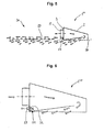
- FIG. 7 shows a further example of an air passage 1 '"" according to the invention, which can be arranged either on a ceiling panel or a support plate of a ceiling sail.
- the air passage 1 ""' is on its surface opposite the air outlet surface 7 with a series of nozzles 27' equipped to blow the supply air to the underside of a concrete ceiling 33, which also takes place a room temperature.
- the air passage 1 ""' in the FIG. 8 is shown enlarged, also has a shut-off device 31 ', by means of which both the inlet cross-section 32' of the nozzle 27 'and between the nozzle 27' and the overflow 15 befind Anlagen flow cross-section 34 can be blocked.
- FIG. 9 a plan view of the ceiling sail 30 after FIG. 5 , wherein in particular the support plate 28, which is attached at a distance to a facade 35, and the air passage 1 "'located in the region of a short side of the support plate 28 can be seen its length L '.
- the supply air introduced through the air inlet nozzle illustrated by arrow 36
- the air inlet nozzle is rotated through 180 ° in the air passage 1 '"and thus flows almost along the entire support plate underside, the flow in towards the arrow 36
- the area of the support plate underside, which is detected by the flow of the air passage 1 "', is indicated by a dashed line 37.
Landscapes
- Engineering & Computer Science (AREA)
- Chemical & Material Sciences (AREA)
- Combustion & Propulsion (AREA)
- Mechanical Engineering (AREA)
- General Engineering & Computer Science (AREA)
- Duct Arrangements (AREA)
Applications Claiming Priority (2)
| Application Number | Priority Date | Filing Date | Title |
|---|---|---|---|
| DE102010001319A DE102010001319A1 (de) | 2010-01-28 | 2010-01-28 | Luftdurchlass mit einem Gehäuse sowie ein Deckensegel mit Luftdurchlass |
| PCT/EP2010/068022 WO2011091886A1 (de) | 2010-01-28 | 2010-11-23 | Luftdurchlass mit einem gehäuse sowie ein deckensegel mit luftdurchlass |
Publications (2)
| Publication Number | Publication Date |
|---|---|
| EP2366082A1 EP2366082A1 (de) | 2011-09-21 |
| EP2366082B1 true EP2366082B1 (de) | 2013-06-26 |
Family
ID=43606428
Family Applications (1)
| Application Number | Title | Priority Date | Filing Date |
|---|---|---|---|
| EP10784497.9A Active EP2366082B1 (de) | 2010-01-28 | 2010-11-23 | Luftdurchlass mit einem gehäuse sowie ein deckensegel mit luftdurchlass |
Country Status (5)
| Country | Link |
|---|---|
| EP (1) | EP2366082B1 (da) |
| DE (1) | DE102010001319A1 (da) |
| DK (1) | DK2366082T3 (da) |
| ES (1) | ES2424959T3 (da) |
| WO (1) | WO2011091886A1 (da) |
Cited By (3)
| Publication number | Priority date | Publication date | Assignee | Title |
|---|---|---|---|---|
| WO2019229044A1 (de) * | 2018-05-30 | 2019-12-05 | Krantz Gmbh | Verdrängungsluftauslass |
| DE102022102497A1 (de) | 2022-02-03 | 2023-08-03 | Krantz Gmbh | Luftdurchlass |
| EP4148331B1 (en) * | 2021-09-14 | 2026-01-28 | Hoffman Enclosures, Inc. | Cover for an air conditioner for sealed enclosures |
Families Citing this family (6)
| Publication number | Priority date | Publication date | Assignee | Title |
|---|---|---|---|---|
| DE102011084423A1 (de) | 2011-10-13 | 2013-04-18 | Yit Germany Gmbh | Gebäude mit einer Raumdecke sowie Verfahren zur Kühlung des Gebäudes |
| DE202016102082U1 (de) | 2016-04-20 | 2016-04-26 | Caverion Deutschland GmbH | Deckensegel |
| DE102016111195A1 (de) | 2016-06-20 | 2017-12-21 | Caverion Deutschland GmbH | Heiz- und Kühlsegel mit mindestens einem Ventilator |
| DE102017125131A1 (de) | 2017-10-26 | 2019-05-02 | Krantz Gmbh | Luftverteilvorrichtung sowie Verfahren zur Belüftung eines Raumes |
| DE202018103628U1 (de) | 2018-06-26 | 2019-09-27 | Krantz Gmbh | Vorrichtung zur Belüftung und Temperierung eines Raums eines Gebäudes |
| DE102022107654A1 (de) | 2022-03-31 | 2023-10-05 | Krantz Gmbh | Vorrichtung zur Belüftung und Temperierung eines Raumes |
Family Cites Families (5)
| Publication number | Priority date | Publication date | Assignee | Title |
|---|---|---|---|---|
| GB316779A (en) * | 1928-08-10 | 1929-08-08 | Alexander William Stewart | Improvements in ventilating apparatus |
| SE351287B (da) * | 1970-02-26 | 1972-11-20 | Svenska Flaektfabriken Ab | |
| DE8805774U1 (de) * | 1988-04-30 | 1988-06-23 | Babcock-BSH AG vormals Büttner-Schilde-Haas AG, 4150 Krefeld | Tunnelmodul zum Aufbau eines Reinraumes in Laminar-Flow-Technik |
| DE4320162C2 (de) * | 1993-06-18 | 1995-11-16 | Krantz Tkt Gmbh | Modul für eine Reinraumdecke |
| DE102007008019B4 (de) | 2007-02-15 | 2018-11-15 | Krantz Gmbh | Luftauslass |
-
2010
- 2010-01-28 DE DE102010001319A patent/DE102010001319A1/de not_active Ceased
- 2010-11-23 EP EP10784497.9A patent/EP2366082B1/de active Active
- 2010-11-23 DK DK10784497.9T patent/DK2366082T3/da active
- 2010-11-23 WO PCT/EP2010/068022 patent/WO2011091886A1/de not_active Ceased
- 2010-11-23 ES ES10784497T patent/ES2424959T3/es active Active
Cited By (4)
| Publication number | Priority date | Publication date | Assignee | Title |
|---|---|---|---|---|
| WO2019229044A1 (de) * | 2018-05-30 | 2019-12-05 | Krantz Gmbh | Verdrängungsluftauslass |
| EP4148331B1 (en) * | 2021-09-14 | 2026-01-28 | Hoffman Enclosures, Inc. | Cover for an air conditioner for sealed enclosures |
| DE102022102497A1 (de) | 2022-02-03 | 2023-08-03 | Krantz Gmbh | Luftdurchlass |
| EP4224077A1 (de) | 2022-02-03 | 2023-08-09 | Krantz GmbH | Luftdurchlass |
Also Published As
| Publication number | Publication date |
|---|---|
| DE102010001319A1 (de) | 2011-08-18 |
| DK2366082T3 (da) | 2013-08-26 |
| WO2011091886A1 (de) | 2011-08-04 |
| ES2424959T3 (es) | 2013-10-10 |
| EP2366082A1 (de) | 2011-09-21 |
Similar Documents
| Publication | Publication Date | Title |
|---|---|---|
| EP2366082B1 (de) | Luftdurchlass mit einem gehäuse sowie ein deckensegel mit luftdurchlass | |
| EP2614196B1 (de) | Anordnung zur belüftung eines raums, insbesondere eines laborraums | |
| EP0497296A2 (de) | Filter-Ventilator-Einrichtung zur Verwendung bei Reinräumen | |
| EP3327366B1 (de) | Luftauslass zum temperieren eines raumes | |
| EP1586823B1 (de) | Decke, insbesondere Kühl- oder Heizdecke | |
| EP3120085B1 (de) | Lüftungsvorrichtung | |
| EP2354686B9 (de) | Deckenluftauslass für Zuluft und Induktion von Raumluft in horizontaler Richtung einer klimatechnischen Anlage | |
| EP2846108A1 (de) | Deckenluftauslass | |
| DE2328186C2 (de) | Induktionsgerät | |
| DE3217803C2 (de) | Einbauteil für eine Mischkammer einer raumlufttechnischen Anlage | |
| EP3285017B1 (de) | Heiz- und kühlsegel mit mindestens einem ventilator | |
| EP0311934B1 (de) | Quell-Luftauslass für Lüftungs- und Klimatisierungszwecke | |
| DE102008031220A1 (de) | Hybridkühlturm | |
| EP0043504B1 (de) | Aussenwandkasten für die Verbrennungsluft- und Abgaskanäle eines mit einem Brennersystem arbeitenden Gerätes | |
| DE20200246U1 (de) | Anordnung zur Erzeugung eines Luftschottes | |
| EP0816772B1 (de) | Luftauslass | |
| DE102019104872A1 (de) | Klimatisierung von Räumen mit Quellluftzuführung und Temperierung | |
| EP3236173B1 (de) | Verfahren zum klimatisieren eines raums | |
| EP3587943B1 (de) | Vorrichtung zur belüftung und temperierung eines raums eines gebäudes | |
| EP3477212B1 (de) | Luftverteilvorrichtung sowie verfahren zur belüftung eines raumes | |
| DE2442378C3 (de) | Deckenluftauslaß | |
| DE4213812A1 (de) | Luftauslaß | |
| DE3025342A1 (de) | Vorrichtung zur belueftung von arbeitsraeumen, insbesondere von fabrikhallen | |
| EP0787954A2 (de) | Vorrichtung für die Einführung von Luft | |
| EP2647918B1 (de) | Einrichtung zum Belüften, zum Heizen und/oder zum Kühlen eines Raumes |
Legal Events
| Date | Code | Title | Description |
|---|---|---|---|
| PUAI | Public reference made under article 153(3) epc to a published international application that has entered the european phase |
Free format text: ORIGINAL CODE: 0009012 |
|
| 17P | Request for examination filed |
Effective date: 20110513 |
|
| AK | Designated contracting states |
Kind code of ref document: A1 Designated state(s): AL AT BE BG CH CY CZ DE DK EE ES FI FR GB GR HR HU IE IS IT LI LT LU LV MC MK MT NL NO PL PT RO RS SE SI SK SM TR |
|
| 17Q | First examination report despatched |
Effective date: 20120402 |
|
| RIN1 | Information on inventor provided before grant (corrected) |
Inventor name: MAKULLA, DETLEF Inventor name: LAUDENBERG, RAINER |
|
| GRAP | Despatch of communication of intention to grant a patent |
Free format text: ORIGINAL CODE: EPIDOSNIGR1 |
|
| DAX | Request for extension of the european patent (deleted) | ||
| INTG | Intention to grant announced |
Effective date: 20130405 |
|
| GRAS | Grant fee paid |
Free format text: ORIGINAL CODE: EPIDOSNIGR3 |
|
| GRAA | (expected) grant |
Free format text: ORIGINAL CODE: 0009210 |
|
| AK | Designated contracting states |
Kind code of ref document: B1 Designated state(s): AL AT BE BG CH CY CZ DE DK EE ES FI FR GB GR HR HU IE IS IT LI LT LU LV MC MK MT NL NO PL PT RO RS SE SI SK SM TR |
|
| REG | Reference to a national code |
Ref country code: GB Ref legal event code: FG4D Free format text: NOT ENGLISH |
|
| REG | Reference to a national code |
Ref country code: CH Ref legal event code: EP |
|
| REG | Reference to a national code |
Ref country code: AT Ref legal event code: REF Ref document number: 618864 Country of ref document: AT Kind code of ref document: T Effective date: 20130715 |
|
| REG | Reference to a national code |
Ref country code: IE Ref legal event code: FG4D Free format text: LANGUAGE OF EP DOCUMENT: GERMAN |
|
| REG | Reference to a national code |
Ref country code: DE Ref legal event code: R096 Ref document number: 502010003824 Country of ref document: DE Effective date: 20130822 |
|
| REG | Reference to a national code |
Ref country code: DK Ref legal event code: T3 |
|
| REG | Reference to a national code |
Ref country code: SE Ref legal event code: TRGR |
|
| REG | Reference to a national code |
Ref country code: NL Ref legal event code: T3 |
|
| REG | Reference to a national code |
Ref country code: NO Ref legal event code: T2 Effective date: 20130626 |
|
| REG | Reference to a national code |
Ref country code: ES Ref legal event code: FG2A Ref document number: 2424959 Country of ref document: ES Kind code of ref document: T3 Effective date: 20131010 |
|
| PG25 | Lapsed in a contracting state [announced via postgrant information from national office to epo] |
Ref country code: FI Free format text: LAPSE BECAUSE OF FAILURE TO SUBMIT A TRANSLATION OF THE DESCRIPTION OR TO PAY THE FEE WITHIN THE PRESCRIBED TIME-LIMIT Effective date: 20130626 Ref country code: LT Free format text: LAPSE BECAUSE OF FAILURE TO SUBMIT A TRANSLATION OF THE DESCRIPTION OR TO PAY THE FEE WITHIN THE PRESCRIBED TIME-LIMIT Effective date: 20130626 Ref country code: SI Free format text: LAPSE BECAUSE OF FAILURE TO SUBMIT A TRANSLATION OF THE DESCRIPTION OR TO PAY THE FEE WITHIN THE PRESCRIBED TIME-LIMIT Effective date: 20130626 Ref country code: GR Free format text: LAPSE BECAUSE OF FAILURE TO SUBMIT A TRANSLATION OF THE DESCRIPTION OR TO PAY THE FEE WITHIN THE PRESCRIBED TIME-LIMIT Effective date: 20130927 |
|
| REG | Reference to a national code |
Ref country code: LT Ref legal event code: MG4D |
|
| PG25 | Lapsed in a contracting state [announced via postgrant information from national office to epo] |
Ref country code: BG Free format text: LAPSE BECAUSE OF FAILURE TO SUBMIT A TRANSLATION OF THE DESCRIPTION OR TO PAY THE FEE WITHIN THE PRESCRIBED TIME-LIMIT Effective date: 20130926 Ref country code: HR Free format text: LAPSE BECAUSE OF FAILURE TO SUBMIT A TRANSLATION OF THE DESCRIPTION OR TO PAY THE FEE WITHIN THE PRESCRIBED TIME-LIMIT Effective date: 20130626 Ref country code: RS Free format text: LAPSE BECAUSE OF FAILURE TO SUBMIT A TRANSLATION OF THE DESCRIPTION OR TO PAY THE FEE WITHIN THE PRESCRIBED TIME-LIMIT Effective date: 20130626 |
|
| PG25 | Lapsed in a contracting state [announced via postgrant information from national office to epo] |
Ref country code: LV Free format text: LAPSE BECAUSE OF FAILURE TO SUBMIT A TRANSLATION OF THE DESCRIPTION OR TO PAY THE FEE WITHIN THE PRESCRIBED TIME-LIMIT Effective date: 20130626 |
|
| PG25 | Lapsed in a contracting state [announced via postgrant information from national office to epo] |
Ref country code: IS Free format text: LAPSE BECAUSE OF FAILURE TO SUBMIT A TRANSLATION OF THE DESCRIPTION OR TO PAY THE FEE WITHIN THE PRESCRIBED TIME-LIMIT Effective date: 20131026 Ref country code: CY Free format text: LAPSE BECAUSE OF FAILURE TO SUBMIT A TRANSLATION OF THE DESCRIPTION OR TO PAY THE FEE WITHIN THE PRESCRIBED TIME-LIMIT Effective date: 20130619 Ref country code: CZ Free format text: LAPSE BECAUSE OF FAILURE TO SUBMIT A TRANSLATION OF THE DESCRIPTION OR TO PAY THE FEE WITHIN THE PRESCRIBED TIME-LIMIT Effective date: 20130626 Ref country code: PT Free format text: LAPSE BECAUSE OF FAILURE TO SUBMIT A TRANSLATION OF THE DESCRIPTION OR TO PAY THE FEE WITHIN THE PRESCRIBED TIME-LIMIT Effective date: 20131028 Ref country code: SK Free format text: LAPSE BECAUSE OF FAILURE TO SUBMIT A TRANSLATION OF THE DESCRIPTION OR TO PAY THE FEE WITHIN THE PRESCRIBED TIME-LIMIT Effective date: 20130626 Ref country code: EE Free format text: LAPSE BECAUSE OF FAILURE TO SUBMIT A TRANSLATION OF THE DESCRIPTION OR TO PAY THE FEE WITHIN THE PRESCRIBED TIME-LIMIT Effective date: 20130626 |
|
| REG | Reference to a national code |
Ref country code: DE Ref legal event code: R082 Ref document number: 502010003824 Country of ref document: DE Representative=s name: BAUER WAGNER PRIESMEYER, PATENT- UND RECHTSANW, DE |
|
| PG25 | Lapsed in a contracting state [announced via postgrant information from national office to epo] |
Ref country code: RO Free format text: LAPSE BECAUSE OF FAILURE TO SUBMIT A TRANSLATION OF THE DESCRIPTION OR TO PAY THE FEE WITHIN THE PRESCRIBED TIME-LIMIT Effective date: 20130626 Ref country code: PL Free format text: LAPSE BECAUSE OF FAILURE TO SUBMIT A TRANSLATION OF THE DESCRIPTION OR TO PAY THE FEE WITHIN THE PRESCRIBED TIME-LIMIT Effective date: 20130626 |
|
| REG | Reference to a national code |
Ref country code: DE Ref legal event code: R081 Ref document number: 502010003824 Country of ref document: DE Owner name: CAVERION DEUTSCHLAND GMBH, DE Free format text: FORMER OWNER: YIT GERMANY GMBH, 80992 MUENCHEN, DE Effective date: 20140217 Ref country code: DE Ref legal event code: R082 Ref document number: 502010003824 Country of ref document: DE Representative=s name: BAUER WAGNER PRIESMEYER, PATENT- UND RECHTSANW, DE Effective date: 20140217 Ref country code: DE Ref legal event code: R082 Ref document number: 502010003824 Country of ref document: DE Representative=s name: PATENT- & RECHTSANWAELTE BAUER WAGNER PRIESMEY, DE Effective date: 20140217 Ref country code: DE Ref legal event code: R081 Ref document number: 502010003824 Country of ref document: DE Owner name: KRANTZ GMBH, DE Free format text: FORMER OWNER: YIT GERMANY GMBH, 80992 MUENCHEN, DE Effective date: 20140217 |
|
| PG25 | Lapsed in a contracting state [announced via postgrant information from national office to epo] |
Ref country code: CY Free format text: LAPSE BECAUSE OF FAILURE TO SUBMIT A TRANSLATION OF THE DESCRIPTION OR TO PAY THE FEE WITHIN THE PRESCRIBED TIME-LIMIT Effective date: 20130626 |
|
| PLBE | No opposition filed within time limit |
Free format text: ORIGINAL CODE: 0009261 |
|
| STAA | Information on the status of an ep patent application or granted ep patent |
Free format text: STATUS: NO OPPOSITION FILED WITHIN TIME LIMIT |
|
| 26N | No opposition filed |
Effective date: 20140327 |
|
| REG | Reference to a national code |
Ref country code: DE Ref legal event code: R097 Ref document number: 502010003824 Country of ref document: DE Effective date: 20140327 |
|
| PG25 | Lapsed in a contracting state [announced via postgrant information from national office to epo] |
Ref country code: MC Free format text: LAPSE BECAUSE OF FAILURE TO SUBMIT A TRANSLATION OF THE DESCRIPTION OR TO PAY THE FEE WITHIN THE PRESCRIBED TIME-LIMIT Effective date: 20130626 |
|
| REG | Reference to a national code |
Ref country code: IE Ref legal event code: MM4A |
|
| PG25 | Lapsed in a contracting state [announced via postgrant information from national office to epo] |
Ref country code: IE Free format text: LAPSE BECAUSE OF NON-PAYMENT OF DUE FEES Effective date: 20131123 |
|
| PG25 | Lapsed in a contracting state [announced via postgrant information from national office to epo] |
Ref country code: SM Free format text: LAPSE BECAUSE OF FAILURE TO SUBMIT A TRANSLATION OF THE DESCRIPTION OR TO PAY THE FEE WITHIN THE PRESCRIBED TIME-LIMIT Effective date: 20130626 |
|
| PG25 | Lapsed in a contracting state [announced via postgrant information from national office to epo] |
Ref country code: TR Free format text: LAPSE BECAUSE OF FAILURE TO SUBMIT A TRANSLATION OF THE DESCRIPTION OR TO PAY THE FEE WITHIN THE PRESCRIBED TIME-LIMIT Effective date: 20130626 |
|
| PG25 | Lapsed in a contracting state [announced via postgrant information from national office to epo] |
Ref country code: MK Free format text: LAPSE BECAUSE OF FAILURE TO SUBMIT A TRANSLATION OF THE DESCRIPTION OR TO PAY THE FEE WITHIN THE PRESCRIBED TIME-LIMIT Effective date: 20130626 Ref country code: LU Free format text: LAPSE BECAUSE OF NON-PAYMENT OF DUE FEES Effective date: 20131123 Ref country code: HU Free format text: LAPSE BECAUSE OF FAILURE TO SUBMIT A TRANSLATION OF THE DESCRIPTION OR TO PAY THE FEE WITHIN THE PRESCRIBED TIME-LIMIT; INVALID AB INITIO Effective date: 20101123 |
|
| PG25 | Lapsed in a contracting state [announced via postgrant information from national office to epo] |
Ref country code: MT Free format text: LAPSE BECAUSE OF FAILURE TO SUBMIT A TRANSLATION OF THE DESCRIPTION OR TO PAY THE FEE WITHIN THE PRESCRIBED TIME-LIMIT Effective date: 20130626 |
|
| REG | Reference to a national code |
Ref country code: FR Ref legal event code: PLFP Year of fee payment: 6 |
|
| REG | Reference to a national code |
Ref country code: FR Ref legal event code: PLFP Year of fee payment: 7 |
|
| REG | Reference to a national code |
Ref country code: FR Ref legal event code: PLFP Year of fee payment: 8 |
|
| REG | Reference to a national code |
Ref country code: DE Ref legal event code: R082 Ref document number: 502010003824 Country of ref document: DE Representative=s name: PATENT- & RECHTSANWAELTE BAUER WAGNER PRIESMEY, DE Ref country code: DE Ref legal event code: R081 Ref document number: 502010003824 Country of ref document: DE Owner name: KRANTZ GMBH, DE Free format text: FORMER OWNER: CAVERION DEUTSCHLAND GMBH, 80992 MUENCHEN, DE |
|
| PG25 | Lapsed in a contracting state [announced via postgrant information from national office to epo] |
Ref country code: AL Free format text: LAPSE BECAUSE OF FAILURE TO SUBMIT A TRANSLATION OF THE DESCRIPTION OR TO PAY THE FEE WITHIN THE PRESCRIBED TIME-LIMIT Effective date: 20130626 |
|
| PGFP | Annual fee paid to national office [announced via postgrant information from national office to epo] |
Ref country code: SE Payment date: 20201123 Year of fee payment: 11 Ref country code: ES Payment date: 20201217 Year of fee payment: 11 Ref country code: DK Payment date: 20201123 Year of fee payment: 11 Ref country code: NO Payment date: 20201118 Year of fee payment: 11 |
|
| REG | Reference to a national code |
Ref country code: DE Ref legal event code: R082 Ref document number: 502010003824 Country of ref document: DE Representative=s name: BAUER WAGNER PELLENGAHR SROKA PATENT- & RECHTS, DE Ref country code: DE Ref legal event code: R082 Ref document number: 502010003824 Country of ref document: DE Representative=s name: BAUER PSU PARTG MBB, DE |
|
| REG | Reference to a national code |
Ref country code: DK Ref legal event code: EBP Effective date: 20211130 |
|
| REG | Reference to a national code |
Ref country code: NO Ref legal event code: MMEP |
|
| PG25 | Lapsed in a contracting state [announced via postgrant information from national office to epo] |
Ref country code: SE Free format text: LAPSE BECAUSE OF NON-PAYMENT OF DUE FEES Effective date: 20211124 Ref country code: NO Free format text: LAPSE BECAUSE OF NON-PAYMENT OF DUE FEES Effective date: 20211130 |
|
| PG25 | Lapsed in a contracting state [announced via postgrant information from national office to epo] |
Ref country code: DK Free format text: LAPSE BECAUSE OF NON-PAYMENT OF DUE FEES Effective date: 20211130 |
|
| REG | Reference to a national code |
Ref country code: ES Ref legal event code: FD2A Effective date: 20230217 |
|
| PG25 | Lapsed in a contracting state [announced via postgrant information from national office to epo] |
Ref country code: ES Free format text: LAPSE BECAUSE OF NON-PAYMENT OF DUE FEES Effective date: 20211124 |
|
| P01 | Opt-out of the competence of the unified patent court (upc) registered |
Effective date: 20230523 |
|
| REG | Reference to a national code |
Ref country code: CH Ref legal event code: U11 Free format text: ST27 STATUS EVENT CODE: U-0-0-U10-U11 (AS PROVIDED BY THE NATIONAL OFFICE) Effective date: 20251201 |
|
| PLCP | Request for limitation filed |
Free format text: ORIGINAL CODE: EPIDOSNLIM1 |
|
| PGFP | Annual fee paid to national office [announced via postgrant information from national office to epo] |
Ref country code: NL Payment date: 20251124 Year of fee payment: 16 |
|
| PGFP | Annual fee paid to national office [announced via postgrant information from national office to epo] |
Ref country code: DE Payment date: 20251130 Year of fee payment: 16 |
|
| PGFP | Annual fee paid to national office [announced via postgrant information from national office to epo] |
Ref country code: GB Payment date: 20251125 Year of fee payment: 16 |
|
| PGFP | Annual fee paid to national office [announced via postgrant information from national office to epo] |
Ref country code: AT Payment date: 20251118 Year of fee payment: 16 |
|
| PGFP | Annual fee paid to national office [announced via postgrant information from national office to epo] |
Ref country code: IT Payment date: 20251121 Year of fee payment: 16 |
|
| PGFP | Annual fee paid to national office [announced via postgrant information from national office to epo] |
Ref country code: FR Payment date: 20251124 Year of fee payment: 16 |
|
| PGFP | Annual fee paid to national office [announced via postgrant information from national office to epo] |
Ref country code: BE Payment date: 20251124 Year of fee payment: 16 |
|
| PGFP | Annual fee paid to national office [announced via postgrant information from national office to epo] |
Ref country code: CH Payment date: 20251201 Year of fee payment: 16 |