EP2366320B1 - Sac d'aspirateur - Google Patents
Sac d'aspirateur Download PDFInfo
- Publication number
- EP2366320B1 EP2366320B1 EP10163462.4A EP10163462A EP2366320B1 EP 2366320 B1 EP2366320 B1 EP 2366320B1 EP 10163462 A EP10163462 A EP 10163462A EP 2366320 B1 EP2366320 B1 EP 2366320B1
- Authority
- EP
- European Patent Office
- Prior art keywords
- vacuum cleaner
- filter bag
- cleaner filter
- folds
- bag
- Prior art date
- Legal status (The legal status is an assumption and is not a legal conclusion. Google has not performed a legal analysis and makes no representation as to the accuracy of the status listed.)
- Active
Links
Images


Classifications
-
- A—HUMAN NECESSITIES
- A47—FURNITURE; DOMESTIC ARTICLES OR APPLIANCES; COFFEE MILLS; SPICE MILLS; SUCTION CLEANERS IN GENERAL
- A47L—DOMESTIC WASHING OR CLEANING; SUCTION CLEANERS IN GENERAL
- A47L9/00—Details or accessories of suction cleaners, e.g. mechanical means for controlling the suction or for effecting pulsating action; Storing devices specially adapted to suction cleaners or parts thereof; Carrying-vehicles specially adapted for suction cleaners
- A47L9/10—Filters; Dust separators; Dust removal; Automatic exchange of filters
- A47L9/14—Bags or the like; Rigid filtering receptacles; Attachment of, or closures for, bags or receptacles
-
- A—HUMAN NECESSITIES
- A47—FURNITURE; DOMESTIC ARTICLES OR APPLIANCES; COFFEE MILLS; SPICE MILLS; SUCTION CLEANERS IN GENERAL
- A47L—DOMESTIC WASHING OR CLEANING; SUCTION CLEANERS IN GENERAL
- A47L11/00—Machines for cleaning floors, carpets, furniture, walls, or wall coverings
- A47L11/40—Parts or details of machines not provided for in groups A47L11/02 - A47L11/38, or not restricted to one of these groups, e.g. handles, arrangements of switches, skirts, buffers, levers
- A47L11/4013—Contaminants collecting devices, i.e. hoppers, tanks or the like
- A47L11/4016—Contaminants collecting devices, i.e. hoppers, tanks or the like specially adapted for collecting fluids
- A47L11/4019—Fill level sensors; Security means to prevent overflow, e.g. float valves
-
- A—HUMAN NECESSITIES
- A47—FURNITURE; DOMESTIC ARTICLES OR APPLIANCES; COFFEE MILLS; SPICE MILLS; SUCTION CLEANERS IN GENERAL
- A47L—DOMESTIC WASHING OR CLEANING; SUCTION CLEANERS IN GENERAL
- A47L5/00—Structural features of suction cleaners
- A47L5/12—Structural features of suction cleaners with power-driven air-pumps or air-compressors, e.g. driven by motor vehicle engine vacuum
- A47L5/22—Structural features of suction cleaners with power-driven air-pumps or air-compressors, e.g. driven by motor vehicle engine vacuum with rotary fans
- A47L5/225—Convertible suction cleaners, i.e. convertible between different types thereof, e.g. from upright suction cleaners to sledge-type suction cleaners
-
- A—HUMAN NECESSITIES
- A47—FURNITURE; DOMESTIC ARTICLES OR APPLIANCES; COFFEE MILLS; SPICE MILLS; SUCTION CLEANERS IN GENERAL
- A47L—DOMESTIC WASHING OR CLEANING; SUCTION CLEANERS IN GENERAL
- A47L9/00—Details or accessories of suction cleaners, e.g. mechanical means for controlling the suction or for effecting pulsating action; Storing devices specially adapted to suction cleaners or parts thereof; Carrying-vehicles specially adapted for suction cleaners
- A47L9/10—Filters; Dust separators; Dust removal; Automatic exchange of filters
- A47L9/12—Dry filters
- A47L9/122—Dry filters flat
-
- A—HUMAN NECESSITIES
- A47—FURNITURE; DOMESTIC ARTICLES OR APPLIANCES; COFFEE MILLS; SPICE MILLS; SUCTION CLEANERS IN GENERAL
- A47L—DOMESTIC WASHING OR CLEANING; SUCTION CLEANERS IN GENERAL
- A47L9/00—Details or accessories of suction cleaners, e.g. mechanical means for controlling the suction or for effecting pulsating action; Storing devices specially adapted to suction cleaners or parts thereof; Carrying-vehicles specially adapted for suction cleaners
- A47L9/10—Filters; Dust separators; Dust removal; Automatic exchange of filters
- A47L9/14—Bags or the like; Rigid filtering receptacles; Attachment of, or closures for, bags or receptacles
- A47L9/1427—Means for mounting or attaching bags or filtering receptacles in suction cleaners; Adapters
- A47L9/1436—Connecting plates, e.g. collars, end closures
-
- B—PERFORMING OPERATIONS; TRANSPORTING
- B01—PHYSICAL OR CHEMICAL PROCESSES OR APPARATUS IN GENERAL
- B01D—SEPARATION
- B01D46/00—Filters or filtering processes specially modified for separating dispersed particles from gases or vapours
- B01D46/52—Particle separators, e.g. dust precipitators, using filters embodying folded corrugated or wound sheet material
- B01D46/521—Particle separators, e.g. dust precipitators, using filters embodying folded corrugated or wound sheet material using folded, pleated material
- B01D46/523—Particle separators, e.g. dust precipitators, using filters embodying folded corrugated or wound sheet material using folded, pleated material with means for maintaining spacing between the pleats or folds
Definitions
- the invention relates to a vacuum cleaner filter bag having a first bag wall comprising a filter material and a second bag wall and a bottom comprising a filter material, wherein the first and second bag walls are connected to each other along a portion of their circumference to the bottom and along the remaining portion of its circumference, wherein the connection between the first bag wall, the second bag wall and the bottom is formed so that the vacuum cleaner filter bag is completely closed, wherein the filter material of the first and the second bag wall is formed of nonwoven fabric, the vacuum cleaner filter bag having an inlet opening through the air to be cleaned into the vacuum cleaner filter bag can flow in, and has a holding plate.
- Vacuum cleaner filter bags are made today mainly from nonwovens. Due to their excellent dust storage capacity, vacuum cleaner filter bags made of nonwoven fabric filter bags made of paper, such as those from the US 3,596,443 are known, almost completely supplanted. The production of filter bags made of nonwovens is fundamentally different from the production of paper bags. Therefore, manufacturing methods and features of paper filter bags are generally not transferable to nonwoven filter bags.
- Vacuum cleaner filter bag of the type mentioned which are thus formed in particular of a first and a second filter wall and a bottom, are sometimes called block bottom bag, also block bottom bag.
- Such vacuum cleaner filter bags made of nonwoven fabric, which are also the subject of the preamble of claim 1, are expensive to manufacture. They are for example from the DE 20 2005 016309 known.
- vacuum cleaner filter bags are also used with side folds.
- Such vacuum cleaner filter bags are from the EP 1 677 660 known.
- the side folds can also be designed ausstülpbar, such as in the DE 20 2007 017 064 or the DE 20 2009 004 433 disclosed.
- folding is defined in the sense of the present invention as a sequence of two or more folds, wherein a single fold in the sense of the present invention is defined in each case by two fold legs and one fold hinge.
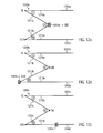
- FIG. 12a shows a side fold 1200a, which consists of a first or upper bag wall 1201a and a second or lower bag wall 1202a. These two bag walls are connected by a weld 1203a.
- To form the side fold three folds I, II and III are provided. Both fold legs of the folds I 1210a and 1211a are formed by the first bag wall and the fold hinge SI of the fold I lies in the first bag wall. Both fold legs of the folds III 1212a and 1213a are formed by the second bag wall and the fold hinge SIII of the fold III lies in the second bag wall.
- the first pleat leg of the pleat II 1211 a is formed by the first bag wall (and corresponds to the second pleat leg of the fold I).
- the second pleat leg of the pleat II 1212a is formed by the second bag wall (and corresponds to the first pleat leg of the pleat III).
- the fold hinge SII of the fold II runs along the weld 1203a.
- FIG. 12b shows a side fold 1200b, which consists of a first or upper bag wall 1201 b and a second or lower bag wall 1202b.
- a side fold 1200b which consists of a first or upper bag wall 1201 b and a second or lower bag wall 1202b.
- To form the side fold three folds I, II and III are provided. Both pleat legs of the pleats I 1210b and 1211b are formed by the first bag wall and the pleat hinge SI of the pleat I lies in the first bag wall. Both pleat legs of the pleat III 1212b and 1213b are formed by the second bag wall and the pleat hinge SIII of the pleat III runs along the weld 1203b.
- connection between the first or upper bag wall of the vacuum cleaner filter bag and the second or lower bag wall of the vacuum cleaner filter bag is realized in the embodiment shown by a fold, namely the fold II with its first pleat leg 1211b (corresponding to the second pleat leg of the pleat I) and its second Pleat leg 1212b (corresponding to the first pleat leg of pleat III).
- FIG. 12c Another alternative for forming a side gusset 1200c according to the prior art is shown.
- the vacuum cleaner filter bag according to FIG. 12c also, there is a first or upper bag wall 1201 c and a second or lower bag wall 1202c.
- To form the side fold three folds 1, II and III are also provided.
- Both pleat legs of the pleats I 1210c and 1211c are formed by the upper bag wall and the pleat hinge SI of the pleat I lies in the upper bag wall.
- Both pleat legs of the pleat III 1212c and 1213c are formed by the lower bag wall and the pleat hinge SIII of the pleat III lies in the lower bag wall.
- the first pleat leg of the pleat II 1211 c is formed by the upper bag wall (and corresponds to the second pleat leg of the fold I).
- the second pleat leg of the pleat II 1212c is formed by the lower bag wall (and corresponds to the first pleat leg of the pleat III).
- the pleat legs of the pleat II and thus the upper and lower bag wall are connected by the folding hinge SII with each other.
- the weld 1203a is located in the lower bag wall.
- the WO 2006/025249 shows a filter bag with multiple side folds.
- vacuum cleaner filter bags In order for the previously described vacuum cleaner filter bags to efficiently fill with dust, they must be made of flexible filter material. Because the filter material is too stiff, then the bag can not unfold during use and do not provide sufficient volume for the dust to be absorbed. If the vacuum cleaner filter bag is to have a gusset, the flexibility of the filter material must also be given, so that such gusset can be provided at all and can also unfold during use again.
- Vacuum cleaner filter bags of various sizes can be folded together so that, despite their different dimensions, they can be offered in packages of the same dimensions, which leads to considerable advantages in terms of warehousing and offering in the showroom.
- Multi-layer filter media made of nonwovens are known.
- a prefiltration by loose fibers for example, in the DE 10 2007 060 747 , of the DE 20 2007 010 692 and the WO 2005/060807 disclosed.
- a pre-separation through a filter bag in the filter bag was through the WO 2010/000453 , the DE 20 2009 002 970 and the DE 20 2006 016 303 disclosed.
- the DE 10 2007 060 748 discloses a filter bag in which the nonwoven material is stretched to form a three-dimensionally shaped bag wall.
- the EP 1 982 625 discloses a filter bag, wherein the filter material is at least partially embossed and by profiling the filter material, the effective filter area is increased. The profiling can be carried out in the form of elongated mutually parallel ribs.
- the DE 20 2005 010 357 discloses a vacuum cleaner filter bag, wherein the bag wall has at least one layer of filter material, wherein at least one layer consists of creped fiber material.
- a coarse filter layer, a fine filter layer or all layers of the bag can be creped.
- a disadvantage of the previously described vacuum cleaner filter bags is that the volume flow of air to be cleaned, which is conveyed through the vacuum cleaner, still decreases considerably as the degree of filling of the vacuum cleaner filter bag increases.
- the dust, ie the cleaning effect of a vacuum cleaner is so much lower in a partially filled vacuum cleaner bag as in a corresponding empty bag.
- This decrease in suction power is particularly strong in filter bags with a high degree of separation (high particle retention or low penetration).
- the object of the present invention is therefore to provide a vacuum cleaner filter bag in which the volume flow of air to be cleaned, which is conveyed through the vacuum cleaner, decreases slightly with increasing filling level of the vacuum cleaner filter bag than in the prior art.
- the invention provides a vacuum cleaner filter bag having a first bag wall comprising a filter material and a second bag wall and a bottom comprising a filter material, wherein the first and second bag walls are interconnected along a portion of their circumference to the bottom and along the remaining portion of its circumference, wherein the connection between the first bag wall, the second bag wall and the bottom is formed so that the vacuum cleaner filter bag is completely closed, wherein the filter material of the first and the second bag wall is formed of nonwoven fabric, the vacuum cleaner filter bag having an inlet opening through the air to be cleaned into the vacuum cleaner filter bag can flow in, and has a holding plate, in which the first and / or the second bag wall has at least five folds.
- surface folds can be provided on the surface of the first and / or second bag wall.
- the surface folding of the filter medium has considerable advantages. Due to the surface folding, the area flowed through is much larger than the regular area available for throughflow (inflow area). This can have several positive effects.
- the service life of the filter is extended proportionally to the area increase, as more filter material is available, can be stored in the dust.
- the service life is defined as the time after which a given filter resistance (pressure loss) is reached.
- the increase in the pressure loss is noticeable in the vacuum cleaner as a reduction in the volume flow (suction air flow) and ultimately as a loss of cleaning effect.
- the speed with which the filter medium flows through decreases.
- a media passage velocity ratio of volume flow to area of the vacuum cleaner filter bag through which flows
- a material thickness of 3.4 mm With a material thickness of 3.4 mm, the bag wall is thus flowed through in about 0.019 s.
- a wrinkled one Bag according to the invention with comparable external dimensions, for example, have a filter area of 3780 cm 2 .
- the result is a media passage speed of 9.3 cm / s and a flow-through time of 0.034 s.
- the lower fluid passage velocity results in a lower pressure drop across the filter medium, ie the initial volume flow (without dust loading of the filter bag) is higher than in a filter bag without the inventive fold.
- the intake power of the vacuum cleaner motor is more effectively converted into a high suction air flow. With the same cleaning performance, a motor with lower power consumption can thus be used.
- each fold as the term is used in connection with the present invention, comprises two pleat legs and one pleat hinge.
- a fold hinge is understood to mean the point of a fold with the smallest radius of curvature. Through the imaginary connection of the fold hinges a so-called fold axis is obtained.
- the fold axis is also called pleat back.
- the fold axis may correspond to the longitudinal axis of a fold.
- Regions of a fold having a radius of curvature greater than the minimum radius of curvature of the fold are referred to as fold legs.
- the area lying between the pleat legs of a fold is referred to as a pleated core.
- the pleat legs of a pleat can thus in particular also have a curvature.
- Wrinkles can also have turning points.
- Turning points are those places of a fold, in particular the pleat legs, to which the curvature of the fold from concave to convex changes.
- a connecting line connecting several turning points of a fold is called an inflexion line (turning line).
- Two adjacent folds can also share a fold leg. If several folds are provided in this way, a fold package or a fold can be realized.
- Folds can also have legs that run parallel to the bag wall. Such legs may lie between folds that protrude from the bag wall plane and thus have an upstream opening with respect to the bag wall.
- the width of the parallel leg may be less than, preferably less than half, or most preferably less than one quarter of, the width of the opening of the fold protruding from the bag wall.
- the pleat legs of the pleats of the first and / or second bag wall may in particular be smooth.
- smooth is meant here that the pleat legs have no densifications and / or structuring, in particular to stabilize the shape of the wrinkles.
- One or more pleat legs of one or more pleats of the first and / or second bag wall may comprise one or more embossed structures, in particular wherein the embossed structures are not used to stabilize the shape of the pleats. As a result, a further enlargement of the available area for filtration can be achieved.
- the first and / or the second bag wall may in particular have more than 5, 10, 20, 30, 40 or 50 folds, in particular also folds of these folds.
- the folds of the first and / or second bag wall may have a substantially regular spacing from each other. In other words, the distance between the fold backs of each two adjacent folds can be substantially constant.
- Folds can be lying or standing. Underlying folds are to be understood as folds whose fold limbs are arranged substantially parallel to the bag wall. Under standing folds are to be understood folds, whose folds legs with the bag wall at an angle greater than 0 ° and less than 180 °, in particular greater than 20 ° or greater 45 ° include.
- a standing fold is also understood to mean a fold in which a plane in which both the fold axis and the fold line of the fold lie, with a flat, horizontal surface, is arranged on the first and / or second bag wall, an angle greater than 45 °, in particular greater than 30 °, in particular greater than 10 °.
- a lying convolution in this case can be understood as a convolution in which the plane with this surface encloses an angle smaller than 45 °, in particular smaller than 30 °, in particular smaller than 10 °.
- the vacuum cleaner filter bag for measuring or determining the above-mentioned angles, is arranged on a flat, horizontal surface.
- the vacuum cleaner filter bag can also be cut open and, in particular be arranged on the surface such that the inflow side or inside of the original vacuum cleaner filter bag rests on the surface.
- Lying convolutions may be mutually overlapping, non-overlapping and / or partially overlapping.
- the folded nonwoven material may comprise one or more layers of nonwoven material. In particular, multiple layers of nonwoven material may be folded together.
- the bag wall may in particular also comprise or consist of a laminate of several layers, in particular two or more layers.
- the laminate may be a spunbonded filament spunbonded microfiber spunbonded nonwoven spunbonded nonwoven laminate (SMS laminate). Also, two or more meltblown nonwoven layers are possible (SMMS laminate, Sn ⁇ MS laminate).
- the bag wall may comprise embossed nonwoven material.
- the retainer plate is generally considered herein to be an element of the vacuum cleaner filter bag used to hold the vacuum cleaner filter bag inside a vacuum cleaner housing.
- the holding plate may in particular be connected to the bag wall of the vacuum cleaner filter bag and arranged in the region of an inflow opening. It can be beneficial be compacted the folds having bag wall in a first step, for example by ultrasonic welding, and in a second step to weld the holding plate.
- the holding plate is connected to a corresponding support member of the vacuum cleaner, in particular brought into engagement.
- the retaining plate can in principle have any shape.
- the retaining plate as a flat, planar component as in the EP 1 849 392 shown to be trained.
- the retaining plate may also have a more complex structure, such as in the DE 20 2008 006 904 shown have.
- the inflow opening and the holding plate can be arbitrarily positioned on the surface of the bag wall of the vacuum cleaner filter bag.
- the inflow opening and the holding plate can be centered on the vacuum cleaner filter bag.
- the bottom may preferably comprise filter material and / or the retaining plate.
- the soil also has filter material, it is particularly preferable to provide it with at least five folds.
- the floor can adapt flexibly to the installation space and contribute to the enlargement of the filter surface.
- the pleat legs of the at least five folds on the first bag wall and / or the second bag wall and / or the bottom have lines of inflection which run essentially straight.
- the fold In contrast to a curved inflexion line, which causes the fold to be stabilized, the fold remains unstiffened by a substantially straight inflexion line.
- the pleat legs may be formed such that they are not stabilized in shape.
- the vacuum cleaner bag remains more flexible overall and the folds can better adapt to the space of a vacuum cleaner.
- the at least five folds on the first bag wall and / or the second bag wall and / or the bottom form at least a surface folding, wherein the maximum height of the surface fold before the first start of the vacuum cleaner filter bag in a vacuum cleaner is smaller than the maximum height corresponding maximum width of the surface folding. How the terms maximum height and maximum width are to be measured here is explained in detail below.
- a vacuum cleaner filter bag may also be provided in which, prior to the first use of the vacuum cleaner filter bag in a vacuum cleaner, each of the at least five pleats has a length greater than one third of the total extent of the vacuum cleaner filter bag in the direction the crease is preferably greater than half the total extension of the vacuum cleaner filter bag in the direction of the crease, and most preferably equal to the total expansion of the bag in the direction of the crease.
- the folds, that is to say in particular the fold axes, of the nonwoven material can run from a first side of the vacuum cleaner filter bag formed by the edge or the hem to a second side of the vacuum cleaner filter bag opposite the first side and formed by the edge or seam.
- An edge or a seam of the vacuum cleaner filter bag can in this case be formed in particular by a welded seam.
- the folds, in particular fold axes, of the nonwoven material can in this case be formed in a straight line.
- the fold axes of the folds may also be formed such that they have no area in which the nonwoven material is fused, welded or plasticized in any form, in particular that they are not formed by a weld.
- the folds of the first and / or second bag wall and / or the bottom of a fold height between 3 mm and 100 mm, in particular between 3 mm and 50 mm, in particular between 5 mm and 15 mm.
- the pleat height can also be greater than 100 mm. This may be the case in particular for large (volume of more than 10 liters), in particular commercially used, vacuum cleaner filter bags.
- the folds of the first and / or second bag wall and / or the bottom may also have a fold width between 3 mm and 100 mm, in particular between 3 mm and 50 mm, in particular between 5 mm and 15 mm.
- the fold width can also be greater than 100 mm. This may be the case in particular for large (volume of more than 10 liters), in particular commercially used, vacuum cleaner filter bags.
- At least two folds of the first and / or second bag wall and / or the bottom may have a different fold height and / or fold width and / or fold shape.
- several or all folds of the first and / or second bag wall may have the same pleat heights and / or pleat widths.
- Another development of the invention provides that a plurality of folds is provided, which are distributed over the first and / or second bag wall and / or the bottom, preferably substantially uniformly.
- the vacuum cleaner filter bag may also include a side fold in addition to the surface fold on the first and / or second bag walls.
- a particularly preferred side folding results when the bag wall regions from which this side fold is formed also have folds which preferably extend at an angle greater than 45 °, most preferably at a substantially right angle, to the side fold.
- the entire filter material can be provided with folds or folds, without the areas from which the side fold is to be formed, must be excluded from this.
- the folds and folds of the first and / or second bag wall and / or bottom may have any shape.
- the pleat legs can also be curved.
- a preferred folding is the so-called dovetail folding.
- a folding with dovetail shape is to be understood in particular as a sequence of four folds with the following configuration.
- the first leg of the first fold and the second leg of the fourth fold are parallel to the bag wall, as well as the second leg of the second fold, which is identical to the first leg of the third fold, parallel to the bag wall.
- the second leg of the first fold is identical to the first leg of the second fold and the second leg of the third fold is identical to the first leg of the fourth fold.
- the folds or folds of the first and / or second bag wall and / or the bottom may each comprise different lengths of pleat legs.
- An edge at which the pleat legs meet, in particular the pleat axis, can be formed by a fold line.
- nonwoven fabric material a dry-laid or wet-laid nonwoven fabric or an extrusion nonwoven fabric, particularly a melt-spun microfiber spunbond fabric (meltblown nonwoven fabric) or spunbonded nonwoven fabric, may be used. There may also be additional nanofiber layers.
- wet laid nonwovens and conventional wet laid paper is made according to the definition given below, as used by the International Association Serving the Nonwoven and Related Industries (EDANA).
- EDANA International Association Serving the Nonwoven and Related Industries
- a conventionally known (filter) paper is therefore not a nonwoven fabric.
- the nonwoven fabric may comprise staple fibers or continuous fibers. Manufacturing technology can also provide several layers of staple fibers or continuous fibers, which are solidified to exactly one layer of nonwoven fabric.
- the bag wall particularly the folded nonwoven material, may comprise a filament spunbond, meltblown nonwoven and spunbond nonwoven fabric (SMS) laminate, as well as other combinations of these layers (SMMS, Sn x MS).
- SMS meltblown nonwoven and spunbond nonwoven fabric
- This laminate may be laminated or calendered by means of a hot melt adhesive.
- the layer of meltblown nonwoven fabric may be creped.
- nonwoven fabric is used in accordance with the definition of ISO standard ISO 9092: 1988 or CEN standard EN29092.
- nonwoven fabric or nonwoven fabric and nonwoven fabric in the field of production of nonwoven fabrics are delimited from one another as follows and also to be understood in the sense of the present invention.
- To produce a nonwoven fabric fibers and / or filaments are used.
- the loose or loose and still unconnected fibers and / or filaments are referred to as nonwoven or nonwoven web.
- non-woven binding step such a non-woven fabric is finally used to form a non-woven fabric which has sufficient strength to be wound into rolls, for example.
- a nonwoven fabric is self-supportingly formed by the solidification.
- the nonwoven material may have (before the pleats are introduced) for vacuum cleaner filter bags for household use a basis weight of less than 250 g / m 2 , in particular less than 200 g / m 2 , in particular between 25 g / m 2 and 150 g / m 2 .
- the nonwoven material (before the folds are introduced) also have a basis weight of about 250 g / m 2. Depending on the mechanical requirement, this may be advantageous, in particular for commercial vacuum cleaner filter bags.
- a fixing device can be provided which prevents at least one of the at least five folds from fully unfolding.
- the folds of a bag wall can be at least partially connected to one another by means of a fixing device.
- a fixing device By means of the fixing device, it is also possible to keep folds of the first and / or second bag wall at a predetermined distance from one another.
- the fixing device may comprise at least one strip of material, in particular a non-woven material strip, or consist of at least one strip of material, in particular at least one strip of non-woven material. Several strips of material may be spaced apart from each other or directly adjacent to each other.
- Several strips of material may run transversely, in particular perpendicularly or at a predetermined angle, to the longitudinal direction of the folds.
- the predetermined angle may be greater than 0 ° and less than 180 °, in particular greater than 30 ° and less than 150 °.
- the fixing device is preferably arranged upstream of the bag wall and / or the bottom. On the inflow side here means facing the interior of the vacuum cleaner filter bag.
- the fixing device may be at least partially connected to the bag wall, in particular with the folds of the first and / or second bag wall, in particular directly connected, in particular adhesively bonded and / or welded. Furthermore, the fixing device can be glued and / or welded at locations where fold limbs of two different folds of the first and / or second pouch wall adjoin one another.
- the fixing device can be glued and / or welded to the bag wall in one or more regions of the bag wall, which are each arranged between two folds of the first and / or second bag wall. In particular, in lying creases that do not overlap each other, thereby a simple production of the vacuum cleaner filter bag can be achieved.
- two or more folds of the first and / or second bag wall can be connected to one another by the fixing device, while two or more folds of the first and / or second bag wall are not connected to one another by the fixing device.
- the fixing device can be glued and / or welded to one or more folds of a bag wall in such a way that the connection is released during operation of the vacuum cleaner filter bag. This can be influenced by the at least partially releasing fixing the air flow within the vacuum cleaner filter bag. In other words, parts of the fixing device can serve as an air distributor during operation of the vacuum cleaner filter bag.
- the vacuum cleaner filter bag can comprise at least one element for flow deflection or flow distribution in the Vacuum cleaner filter bags, in particular, wherein the element in the air flow of the air flowing into the vacuum cleaner filter bag can move.
- an element is for example from the EP 1 787 560 or the EP 1 804 635 known.
- such an element may be in the form of at least one strip of material attached to the bag wall inside the vacuum cleaner filter bag, or may comprise such a strip of material.
- such an element may correspond to at least one strip of nonwoven fabric or filter paper or at least comprise a strip of nonwoven fabric or filter paper.
- the at least one strip of material may be at least partially slotted.
- such an element may be in the form of at least one strip of material attached to a side of the bag wall opposite the inflow opening of the vacuum cleaner filter bag, inside the vacuum cleaner filter bag.
- the at least one strip of material may, in particular directly, be connected to the folded bag wall. It can thereby be achieved that the at least one strip of material can move well in the air flow of the air flowing into the vacuum cleaner filter bag, since the air can reach at least one fold under the at least one strip of material via the pleated core.
- the fixing device may be designed such that the fold width and / or the spacing of the folds or folds which are connected to one another by the fixing device, is kept substantially constant during operation of the vacuum cleaner filter bag.
- the fixing device may have a predetermined expansion behavior.
- a better adaptation of the vacuum cleaner filter bag can be achieved during operation on the available space in the vacuum cleaner.
- a predetermined expansion behavior is understood to mean that the length of the fixing device is changeable, in particular enlargeable, in the pulling direction of an engaging force.
- the fixing device can be designed such that the width of the folds or folds and / or their distance from each other during operation of the bag by changing an extension of the fixing device in at least one direction, in particular in a direction perpendicular to the longitudinal direction of the folds, be enlarged can. It can thereby be achieved that, during operation, the vacuum cleaner filter bag can make the best possible use of the space available in the vacuum cleaner.
- the change in the extent may correspond in particular to an increase in the extent or length of the fixing device.
- the change in expansion can be achieved by stretching the material of the fixing device.
- the change in the extent can be achieved by a geometric deformation of the fixing device.
- the fixing device may be in the form of a net, wherein the shape or geometry of the meshes of the net can be changed under tensile load.
- the fixing device may also be creped, wherein the creping runs parallel to the folds of the first and / or second bag wall. As a result, a change in the extent of the fixing device can be achieved during operation of the vacuum cleaner filter bag.
- the fixing device can also be at least partially folded, in particular wherein the folds run parallel to the folds of the first and / or second bag wall.
- the fold height of the folds of the fixing device can be used to determine the change in the extent of the fixing device to be achieved.
- the fixing device may have an elasticity which is selected such that the fixing device returns to its original shape after operation of the vacuum cleaner filter bag, that is, after switching off the vacuum cleaner. As a result, the change in the extent of the fixing device can be made reversible.
- the fixing device may also be partially, in particular in sub-areas, formed by stretchable strips of material and partially, in particular in other sub-areas, by non-stretchable strips of material.
- the vacuum cleaner filter bag can be adapted to the installation space of a vacuum cleaner.
- the material of the fixing device may have a high air permeability. If the material of the fixing device is impermeable to air, the fixing device may be perforated and / or slotted.
- the fixing device may be in the form of at least one continuous adhesive strip.
- the adhesive in particular, a hot melt adhesive (hot melt) can be used.
- the fixing device can be executed in the form of a continuous or interrupted weld.
- the at least one strip of material may have a width of 0.5 cm to 4 cm, in particular of 1 cm to 3 cm, for example 2 cm.
- the at least one strip of material may have a thickness of 0.1 mm to 10 mm, in particular of 0.3 mm to 4 mm.
- the fixing device may be in the form of one or two strips of material whose width and / or length correspond to the width and / or length of the bag wall. In other words, the fixing device can be formed over the entire surface.
- the fixing device may comprise a nonwoven material, a film and / or a paper.
- nonwoven material for the fixing device for example, filament spunbonded nonwoven fabrics, carded or airlaid nonwoven fabrics and / or laminates of a plurality of nonwoven fabrics are possible.
- the different nonwoven fabric layers may have a gradient in pore diameter.
- the fixing device can also be designed in the form of a fabric or a net.
- the fixing device may be in the form of an extruded net.
- the mesh size of the network can be between 0.5 mm and 10 cm, in particular between 3 mm and 6 mm.
- the shape of the holes of the net can be square or rectangular.
- One or more holes of the mesh may be square and one or more holes of the mesh may be rectangular.
- the fixing device may also comprise filaments, tows and / or yarns.
- the fixing device may be arranged parallel to the bag wall, in particular parallel to an outer surface of the bag wall.
- the outer surface of the bag wall can be understood here a surface in which lie the fold axes of the folds of the first and / or second bag wall, or a parallel to it surface.
- the fixing device may also correspond to or comprise a holding plate of the vacuum cleaner filter bag.
- the folds of the first and / or second Bag wall at least partially connected to each other by means of the holding plate of the vacuum cleaner filter bag.
- a nonwoven material of the fixing device may (optionally before folding) have a weight per unit area of 5 g / m 2 to 250 g / m 2 .
- the fixing device can also be designed as a prefilter layer.
- the fixing device itself may be formed as a filter layer.
- the basis weight of the fixing device may be smaller than 200 g / m 2 .
- the fuser may correspond to a laminate of one or more filament spunbond webs and one or more meltblown microfiber spunbond webs, particularly wherein the at least one meltblown microfiber spunbond web comprises electrostatically charged fibers.
- fibers and / or absorbents may be arranged in a cavity formed by the fixing device and the fold limbs of at least one fold of the nonwoven material (pleated core).
- the fibers may in particular be electrostatically charged fibers.
- the fibers can be coated.
- absorbents for example, porous polymers and / or activated carbon can be used.
- Absorbents based on coated polymer fibers are, for example, by the DE 10 2004 009 956 and the EP 1 725 153 disclosed.
- the porous polymer for example, the crosslinked SDVB (styrene-divinylbenzene) can be used.
- Absorbents which may also be used are impregnated activated carbon, functionalized carbon, hydrophobic zeolites, hydrophobic, porous polymers, bentonites and / or crystalline organometallic complexes.
- the bag wall in particular the folded nonwoven material and / or the fixing device, may be at least partially electrostatically charged. It can be the fibers of the Nonwoven material prior to solidification and / or the nonwoven fabric, so after solidification, are charged electrostatically.
- the electrostatic charge can be achieved, for example, by a corona process.
- the web or nonwoven web is centered in a range of about 1.5 inches (3.8 cm) to 7.6 cm (3 inches) wide between two DC corona discharge electrodes.
- one of the electrodes can have a positive DC voltage of 20 to 30 kV while the second electrode has a negative DC voltage of 20 to 30 kV.
- the vacuum cleaner filter bag may in particular be a disposable vacuum cleaner filter bag.
- the vacuum cleaner filter bag can be designed such that the space utilization of the vacuum cleaner filter bag during operation is greater than 65%, in particular greater than 80%.
- the space utilization can be influenced by appropriate choice of one or more properties of the nonwoven material and / or a fixing device used.
- a fold in the sense of the present invention is defined in each case by two fold legs and a fold hinge.
- the length of the pleat hinge defines in such a fold the length of the pleat.
- a fold in the sense of the present invention is a sequence of two or more folds.
- a side fold is a sequence of folds in the area of the side edge of the vacuum cleaner filter bag.
- the seam along the respective side edge of the vacuum cleaner filter bag is in this case a part of one of the folds forming the side fold;
- the hem in the region of the respective side edge is a pleat hinge or the hem is almost completely in a pleat leg.
- a surface fold is a sequence of folds provided on the bag wall. Such surface folding is at best fixed by a part of the seam along a side edge. However, this part of the hem is neither a fold hinge nor a component of the pleat leg of one of the folds of the fold.
- the air permeability is determined according to DIN EN IS09237: 1995-12. In particular, a differential pressure of 200 Pa and a test area of 20 cm 2 are used .
- the air permeability tester FX3300 from Texttest AG was used to determine the air permeability.
- the basis weight is determined according to DIN EN 29073-1: 1992-08.
- DIN EN 29073-1 1992-08.
- the method according to standard DIN EN ISO 9073-2: 1997-02 is used, method A being used.
- Penetration NaCl permeability
- TSI 8130 tester a TSI 8130 tester.
- 0.3 ⁇ m sodium chloride is used at 86 L / min.
- the width of a multi-fold surface fold in the first and / or second pouch wall is defined for a given cross-section through the fold as a projection of the maximum extent of surface fold on the pouch wall plane.
- the height of a multi-pleated surface fold in the first and / or second bag walls is defined for a given cross-section through the fold as a projection of the maximum extent of surface fold to the normal to the bag wall plane.
- the maximum height of a surface fold is defined here as the greatest height of the surface fold along its entire length.
- the maximum width of a surface fold corresponding to the maximum height is the largest width having the surface fold in the plane containing the maximum height and perpendicular to the axis of the surface fold.
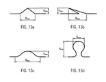
- FIGS. 13a to 13d Illustrative examples are given for determining the maximum height and width of a surface fold. Shown in each case is a cross section through a surface fold in the plane in which the maximum height of the fold is along its length and which is perpendicular to the fold axis. In this cross section, the maximum height H max and the maximum width B max are shown. In the examples according to the FIGS. 13a to 13c surface folds are shown whose maximum height is less than the maximum width; in FIG. 13d a surface fold is shown whose maximum height is greater than its maximum width. The in the FIGS. 13a to 13d folds shown are all standing folds. A lying convolution would be obtained, if one in the FIG. 13b as the height of the fold H max can go to zero.
- the maximum usable volume of the dust chamber of the vacuum cleaner filter bag is determined in accordance with DIN EN 60312-1: 2009.
- the theoretical volume of the installation space of the vacuum cleaner can be calculated from geometric data of the installation space, in particular wherein the space between existing in the space ribs, which serve to support the vacuum cleaner filter bag and to space from the wall surface of the space of the vacuum cleaner, is not calculated to the theoretical volume.
- the theoretical volume of the installation space can be determined, for example, by placing a surface in a computer model of the installation space by means of a computer, which surface rests on the inner wall surface of the installation space, in particular directly. If the installation space has ribs which serve to support the vacuum cleaner filter bag and to space it from the wall surface of the installation space of the vacuum cleaner, the surface may also correspond to a surface parallel to the inner wall surface, which rests on the upper edges of these ribs, in particular directly. The volume enclosed by this surface may correspond to the theoretical volume of the installation space.
- FIG. 1 shows an exemplary vacuum cleaner filter bag comprising a first bag wall 104 and a second bag wall hidden by the first bag wall.
- the first and second bag walls are interconnected by three welds 120, 130, and 140.
- the vacuum cleaner filter bag further comprises a bottom 103, which in the present embodiment has the shape of a holding plate.
- This bottom 103 is connected to the first bag wall by a first adhesive seam and to the second bag wall by a second adhesive seam; the adhesive seams are located on the invisible back of the support plate and are therefore indicated by an arrow 110a for the first adhesive seam and an arrow 110b for the second adhesive seam.
- the vacuum cleaner filter bag after FIG. 1 also includes an inflow port 102 through which air to be cleaned can flow into the vacuum cleaner filter bag.
- the holding plate is used for fixing the vacuum cleaner filter bag in a chamber of a vacuum cleaner and has a through hole in the region of the inflow opening 102.
- the folded nonwoven material comprises a plurality, in particular more than two, folds 101.
- the folds 101 are formed here as lying folds. A lying convolution is obtained when looking at the in FIG. 13b folding shown the height H max can go to zero.
- other folds, in particular standing folds, as will be described below or as they are described in the following FIGS. 13a to 13c shown are possible.
- the bag wall may in particular comprise two or more filter layers, wherein at least one layer comprises the folded nonwoven material.
- the bottom 103 is indeed in the execution after FIG. 1 provided in the form of a holding plate, but may alternatively comprise filter material to increase the total filter area, on which the retaining plate in a known manner, for example by gluing, is attached.
- the filter material of the soil may, but need not, also have folds.
- the folds run in the in FIG. 1 shown embodiments transverse to the longitudinal axis of the vacuum cleaner filter bag. It is alternatively also possible to let the folds run parallel or at an angle to this longitudinal axis.
- FIG. 2 shows an oblique view of an inside of a bag wall of an exemplary vacuum cleaner filter bag.
- the pleats 201 of the nonwoven material are connected together in this example by a fixing device in the form of a plurality of strips of material 205.
- the pleats 201 are held by the strips of material 205 at a predetermined distance from each other.
- the fold width of the folds 201 is fixed by the material strips 205.
- the material strips 205 are connected at connection points 206 with the folds 201, in particular with an edge of the folds 201, for example glued or welded.
- the arrow 210 indicates the direction of flow of the air to be cleaned through the nonwoven material.
- the material strips 205 may, for example, have a width of 0.5 cm to 4 cm, in particular from 1 cm to 3 cm, for example 2 cm.
- the material strips 205 may comprise a nonwoven material.
- the nonwoven material may in particular comprise extrusion nonwoven fabric, for example a filament spunbonded nonwoven, and / or a carded or airlaid nonwoven fabric.
- the strips of material 205 may also comprise a laminate of a plurality of nonwoven fabrics, in particular a filament spunbonded nonwoven laminate - melt spun microfiber spunbond nonwoven - filament spunbond web.
- the basis weight of the material strips 205 can be less than 250 g / m 2 , in particular between 10 g / m 2 and 30 g / m 2 .
- connection points 206 may be formed such that the connection dissolves during operation of the vacuum cleaner filter bag. By the at least partially dissolved strips of material 205, the flow behavior of the air flowing into the bag can be influenced.
- the material strips 205 may also have a predetermined elongation behavior. Thus, a predetermined expansion of the bag can be achieved during operation.
- the material strips 205 may also have an elasticity, so that the expansion of the bag after operation, ie after switching off the vacuum cleaner, is reduced again by elastic restoring forces. This also allows dust to be carried from the bag wall to the interior of the vacuum cleaner filter bag.
- the fixing device can also be designed as a full-surface material strip.
- the fixing device can have a high air permeability, in particular more than 5000 l / (m 2 s).
- the fixing device may also comprise an air-permeable paper, tissue and / or a film.
- the fixing device can also be perforated and / or slotted.
- FIG. 3 shows an oblique view of an inner side of a bag wall of another exemplary vacuum cleaner filter bag.
- the fixing device is in the form of a net 307 which connects the folds 301 of the nonwoven material in a partial area of the surface. In other areas of the surface, the folds of the first and / or second bag walls are not connected by the fixing device.
- the arrow 310 indicates the direction of flow of the air to be cleaned through the nonwoven material.
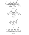
- FIG. 4 shows a cross section through a portion of the bag wall of an exemplary vacuum cleaner filter bag, wherein the cross section is perpendicular to the course of the folds of the first and / or second bag wall.
- FIG. 4 shows FIG. 4 a zig-zag fold of three folds 401 comprising seven pleats I-VII.
- the pleats I, I II, V and VII are connected to each other by a fixing device 405.
- the fixing device 405 is connected at connection points 406 to the fold hinges of these folds.
- the arrow 410 indicates the direction of flow of the air to be cleaned to the bag wall. In this example, the fixing device 405 is thus upstream with respect to the bag wall.
- FIG. 4 also shows the pleat width B max and the pleat height H max of the pleats.
- the pleat height h and / or the pleat width b can be between 3 mm and 100 mm, in particular between 5 mm and 15 mm.
- the folds are standing folds; one part of the pleat legs here has an angle ⁇ of about 64 °, the other part of the pleat legs an angle ⁇ of about 116 °.
- FIG. 5 shows a further cross-section through part of a bag wall of an exemplary vacuum cleaner filter bag.
- two folds 501 from six folds I-VI are shown in the cut-out, and a fixing device 505 arranged upstream with respect to the inflow direction 510, which are connected at connection points 506 to the folds I, III or IV and VI.
- connection point 506.1 is arranged in the region of the nonwoven material which forms the leg of the folds III and IV and runs parallel to the bag wall.
- the folds of this vacuum cleaner bag thus have legs that are parallel to the bag wall and lie between the folds that protrude from the bag wall plane.
- the width of the parallel leg is smaller than the width of the opening of the protruding from the bag wall fold.
- FIG. 6 shows a cross section through a portion of a bag wall of an exemplary vacuum cleaner filter bag, in which the folds 601 have different lengths of pleat legs in cross section.
- the cavities formed between the folds and the fixing device can be filled with fibers, in particular electrostatically charged fibers, and / or with absorbents.
- fibers in particular electrostatically charged fibers, and / or with absorbents.
- absorbents for example, coated fibers, activated carbon and / or porous polymers can be used as absorbents.
- FIG. 7 a cross section of a portion of such a bag wall.
- a plurality of folds 701 are shown forming triangular folds.
- a fixing device 705 is connected to a part of the folds.
- fibers 711 and / or activated carbon 712 are arranged in the cavities between the Folded legs and the fixing device 705 .
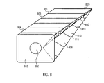
- FIG. 8 shows an exemplary vacuum cleaner filter bag in plan view of an outside of the vacuum cleaner filter bag.
- the vacuum cleaner bag has an upper or first bag wall 804 and a lower or second bag wall 805. Further, the vacuum cleaner filter bag has a bottom 803 formed as a holding plate and having an inflow port 802.
- the upper bag wall 804 and the lower bag wall 805 are defined by three welds, one of which FIG. 8 two are visible, connected. These are identified by the reference numerals 820 and 830.
- the vacuum cleaner filter bag In the area of the weld seam 830, the vacuum cleaner filter bag has a side fold 813. Accordingly, there is also another side fold in the region of the weld seam 813 which is not visible.
- the upper bag wall 804 and the lower bag wall 805 include a plurality of recumbent folds 801. Also, folds 811 are provided in the area of the side folds (see particularly at 813). These folds 811 are here also lying folds and extend substantially perpendicular to the hinge of the side fold.
- the side folds may also have an unfolded filter material.
- the folds could also run parallel to the longitudinal axis of the bag.
- the folds have the shape of a triangle.
- the folds can also have any other shape.
- the shape of the folds in the figures is only to be understood schematically.
- the pleat legs can also be curved.
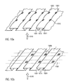
- the fold shape of one or more folds and / or folds of the first and / or second bag wall may have a dovetail shape in a cross section perpendicular to the longitudinal axis of the folds. Examples of folds with a dovetailed cross-section are shown in FIGS Figures 10a and 10b shown.
- the edges 1015 of the pleat legs of the pleats 1001 pointing towards the interior of the bag are arranged at a distance from each other. This allows the air to be cleaned easily penetrate into the fold.
- the direction in which the air to be cleaned flows through the bag wall is illustrated by an arrow 1010.
- the pleats 1002 of the nonwoven material are respectively connected to the parallel legs of the pleats 1001, in particular adhesively bonded and / or welded.
- the connecting points 1016 have a distance to one another in the longitudinal direction of the pleats 1002 that is greater than 1/5, in particular greater than 1/4, the length of the pleat 1002.
- the pleats 1002 can be better flowed through the air to be cleaned during operation than at smaller distances between junctions 1016.
- connection points 1016 may also lie on a continuous welding line.
- a fixing device 1105 is provided in the form of a plurality of strips of material, which is glued and / or welded to the at least folded nonwoven material with the pleat legs of the folds 1001.
- multiple connection points 1006 are shown.
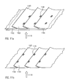
- FIGs 11 A and 11B show further exemplary sections of a bag wall with a nonwoven material having surface folds.
- the folds formed from the pleats 1101, 1102 and 1103 of the nonwoven material are formed lying in these examples, ie, the pleat legs are substantially parallel to the surface of the bag wall. Since substantially parallel to the surface extending pleat legs are graphically not represented, the pleat legs were shown here at an angle with respect to the surface of the bag wall.
- FIG. 11a In addition, a fixing device 1105 is shown, which is connected to the surface provided with nonwoven fabric material in areas of the bag wall, in particular glued and / or welded, which form the fold limbs of the folds 1101.
- a fixing device 1105 is shown, which is connected to the surface provided with nonwoven fabric material in areas of the bag wall, in particular glued and / or welded, which form the fold limbs of the folds 1101.
- the fixing device 1105 is in FIG. 11a formed over the entire surface.
- the fixing device 1105 could also be in the form of a plurality of strips of material, as illustrated for example in FIG.
- connection points 1106 can also lie on a continuous welding line, which preferably runs parallel to the fold axes.
- the folds 1101 of the nonwoven material are respectively connected to the fold limbs of the folds 1102, in particular glued and / or welded, which is arranged between two fold edges of the pouch wall.
- the connecting points 1116 have a distance from each other in the longitudinal direction of the pleats 1101 that is greater than 1/5, in particular greater than 1/4, the length of the pleat 1101.
- the pleats 1101 can be better flowed through the air to be cleaned during operation than at smaller distances between junctions 1116.
- connection points 1116 may also lie on a continuous welding line, which preferably runs perpendicular to the fold axes.
- the area available for filtration can be increased at given dimensions of the vacuum cleaner filter bag. This leads to a high separation efficiency with low initial pressure loss. This is accompanied by a lower media passage speed, which increases the separation efficiency, in particular by electrostatically charged fibers of the bag wall.
- vacuum cleaner filter bag may be formed in different geometries and / or sizes.
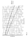
- FIG. 9 serves as an illustration and shows a diagram showing the volume flow through the vacuum cleaner (Vorwerk VK 140) as a function of the dust load (DMT-8 dust) in grams.
- the bag walls each consist of a SMMS laminate of an outer layer of spunbonded nonwoven (35 g / m 2 ) two layers of meltblown nonwoven fabric (2 x 20 g / m 2 ) and an inner layer of spunbonded fabric (17 g / m 2 ).
- Example 1 Block bottom bag according to the prior art (without surface folds).
- the shape of this vacuum cleaner filter bag is the same as the shape of the in FIG. 8 shown vacuum cleaner filter bag.
- the vacuum cleaner filter bag according to Example 1 has no surface folds.
- the bottom next to the retaining plate also includes filter material without surface folds.
- the width of the vacuum cleaner filter bag is 140 mm (corresponds to the width along the weld 820 in FIG. 8 ).
- the length of the vacuum cleaner filter bag (corresponding to the length along the upper bag wall from the holding plate to the weld) is 240 mm.
- the height of the vacuum cleaner bag in the area of the bottom is 85 mm.
- the retaining plate measures about 65 mm ⁇ 70 mm.
- Example 2 Block bottom bag with surface folds in dovetail shape.
- the vacuum cleaner filter bag has the same shape and size as Examples 1.
- on the bag top and the bag bottom are each 3 dovetails with a first leg with a length of 15 mm, a second - parallel to the bag wall - leg with a length of 40 mm and a third leg of 15 mm again.
- the soil however, has no surface folds.
- the vacuum cleaner filter bags with a bag wall comprising a folded nonwoven material, even at high dust loads a larger volume flow, as a vacuum cleaner filter bag with a bag wall without folds in the nonwoven material.
- the higher dust storage capacity reduces the pressure loss increase of the vacuum cleaner filter bag.
- Filter medium 1 is an SMMS laminate of an outer layer of spunbonded nonwoven (35 g / m 2 ) two layers of meltblown nonwoven fabric (2 x 20 g / m 2 ) and an inner layer of spunbonded fabric (17 g / m 2 ).
- Filter medium 2 is a SMMMMS laminate of an outer layer of spunbonded non-woven (35 g / m 2 ) four layers of meltblown nonwoven fabric (4 x 19 g / m 2 ) and an inner layer of spunbonded fabric (17 g / m 2 ).
- Table 1 The different media throughput speeds were determined by changing the volume flow on the TS! 8130 set. It was worked with test specimens with an area of 100 cm ⁇ sup> 2 ⁇ / sup>.
- TSI 8130 Media passage velocity [cm / s] Pressure drop ⁇ P [mm H 2 O] Penetration [%] Filter medium 1 14.3 14.5 32.2 7.15 6.9 18.7 Filter medium 2 14.3 32.1 0,025 7.15 15.5 0,004
- the pressure loss and the penetration in the filter medium and the flow rate corresponding to a folded bag wall are significantly lower than the filter medium and the flow rate corresponding to the prior art (unfolded). With the lower media passage velocity, the pressure loss is only about half as high in the case of the two filter media considered as with the high media passage speed.
- the separation efficiency improves significantly at the lower medium throughput rate.
- the reduction of penetration is disproportionately stronger in the filter medium 2 than in the filter medium 1, because in this case the effect of the electrostatic charge of the filter material comes to bear even more than in the more open material. 1
- an optimal adaptation of the vacuum cleaner filter bag during operation to the predetermined installation space in the vacuum cleaner can be achieved.
- a space utilization of more than 65% can be achieved.
- a space utilization of more than 80% can be achieved.
Landscapes
- Engineering & Computer Science (AREA)
- Mechanical Engineering (AREA)
- Chemical & Material Sciences (AREA)
- Chemical Kinetics & Catalysis (AREA)
- Filters For Electric Vacuum Cleaners (AREA)
- Filtering Materials (AREA)
- Filtering Of Dispersed Particles In Gases (AREA)
Claims (19)
- Sac filtrant d'aspirateur comprenant une première paroi de sac (104; 804) comportant un matériau filtrant, et une deuxième paroi de sac comportant un matériau filtrant, ainsi qu'un fond (103; 803), sac dans lequel la première et la deuxième paroi de sac sont reliées ou connectées respectivement au fond le long d'une partie de leur pourtour, et entre elles le long de la partie restante de leur pourtour (120, 130, 140; 820, 830), dans lequel la liaison entre la première paroi de sac, la deuxième paroi de sac et le fond, est conçue pour que le sac filtrant d'aspirateur soit entièrement fermé, dans lequel le matériau filtrant de la première et de la deuxième paroi de sac est constitué d'un matériau non-tissé, et dans lequel le sac d'aspirateur comporte une ouverture d'entrée (102; 902) à travers laquelle l'air à purifier ou nettoyer peut pénétrer dans le sac filtrant d'aspirateur, ainsi qu'une plaque de rétention ou plaque d'embout de maintien (103; 803),
caractérisé en ce que
la première et/ou la deuxième paroi de sac comportent au moins cinq plis (101; 801). - Sac filtrant d'aspirateur selon la revendication 1, dans lequel le fond comporte un matériau filtrant et/ou la plaque d'embout de maintien.
- Sac filtrant d'aspirateur selon la revendication 2, dans lequel le matériau filtrant constituant le fond présente au moins cinq plis.
- Sac filtrant d'aspirateur selon l'une des revendications précédentes, dans lequel les flancs ou jambes de pli desdits au moins cinq plis comportent des lignes d'inflexion, qui s'étendent essentiellement de manière rectiligne.
- Sac filtrant d'aspirateur selon l'une des revendications précédentes, dans lequel lesdits au moins cinq plis forment un pliage de surface, dans lequel la hauteur maximale du pliage de surface (Hmax) est, avant la première mise en service du sac filtrant d'aspirateur dans un aspirateur, inférieure à la largeur maximale du pliage de surface (Bmax) correspondant à la hauteur maximale.
- Sac filtrant d'aspirateur selon l'une des revendications précédentes, dans lequel, avant la première mise en service du sac filtrant d'aspirateur dans un aspirateur, chacun desdits au moins cinq plis (101; 801) présente une longueur, qui est supérieure à un tiers de l'extension totale du sac filtrant d'aspirateur dans la direction du pli, qui de préférence est supérieure à la moitié de l'extension totale du sac filtrant d'aspirateur dans la direction du pli, et qui correspond de manière particulièrement préférée à l'extension totale du sac dans la direction du pli.
- Sac filtrant d'aspirateur selon l'une des revendications précédentes, dans lequel, avant la première mise en service du sac filtrant d'aspirateur dans un aspirateur, chacun desdits au moins cinq plis présente une hauteur comprise entre 3 mm et 100 mm, en particulier entre 3 mm et 50 mm, et plus particulièrement encore entre 5 mm et 15 mm.
- Sac filtrant d'aspirateur selon l'une des revendications précédentes, dans lequel, avant la première mise en service du sac filtrant d'aspirateur dans un aspirateur, chacun desdits au moins cinq plis présente une largeur comprise entre 3 mm et 100 mm, en particulier entre 3 mm et 50 mm, et plus particulièrement encore entre 5 mm et 15 mm.
- Sac filtrant d'aspirateur selon l'une des revendications précédentes, dans lequel au moins deux desdits au moins cinq plis présentent des hauteurs et/ou des largeurs et/ou des formes qui diffèrent entre elles.
- Sac filtrant d'aspirateur selon l'une des revendications précédentes, dans lequel est prévue une pluralité de plis (101; 801), qui sont distribués ou répartis sur les première et/ou deuxième parois de sac, de préférence de manière essentiellement uniforme.
- Sac filtrant d'aspirateur selon l'une des revendications précédentes, comportant, en outre, au moins un pliage latéral (813), qui est formé par la première et/ou la deuxième paroi de sac.
- Sac filtrant d'aspirateur selon la revendication 11, dans lequel ledit au moins un pliage latéral comporte pour sa part, au moins un pli qui s'étend de préférence selon un angle supérieur à 45° par rapport au pliage latéral, et de manière particulièrement préférée selon un angle sensiblement droit par rapport au pliage latéral.
- Sac filtrant d'aspirateur selon l'une des revendications précédentes, dans lequel il est prévu un dispositif de fixation (205; 307), qui empêche que l'un au moins desdits cinq plis ne se déplie entièrement.
- Sac filtrant d'aspirateur selon la revendication 13, dans lequel le dispositif de fixation est agencé du côté amont de l'écoulement par rapport auxdites première et/ou deuxième parois de sac et/ou au fond.
- Sac filtrant d'aspirateur selon la revendication 13 ou la revendication 14, dans lequel le dispositif de fixation est collé et/ou soudé audit au moins un pli et/ou à la paroi de sac adjacente audit au moins un pli.
- Sac filtrant d'aspirateur selon l'une des revendications 13 à 15, dans lequel le dispositif de fixation comporte au moins une bande de matériau (205), en particulier une bande de matériau non tissé, et/ou dans lequel le dispositif de fixation présente un comportement prédéterminé d'extension et/ou un comportement élastique prédéterminé.
- Sac filtrant d'aspirateur selon l'une des revendications 13 à 15, dans lequel le dispositif de fixation est une couche de matériau non tissé, une couche en treillis (307), un film perforé ou une couche de tissu, qui s'étend sur l'ensemble de la première et/ou de la deuxième paroi de sac.
- Sac filtrant d'aspirateur selon l'une des revendications 13 à 17, dans lequel des fibres et/ou des matières absorbantes sont prévues dans une cavité qui est formée par le dispositif de fixation et les flancs ou jambes de pli dudit au moins un pli.
- Appareil aspirateur avec un sac filtrant d'aspirateur selon l'une des revendications précédentes, dans lequel l'appareil aspirateur et le sac filtrant d'aspirateur sont d'une constitution telle, que l'utilisation de l'espace d'installation du sac filtrant d'aspirateur dans l'appareil aspirateur lors du fonctionnement de celui-ci, soit supérieure à 65%, en particulier supérieure à 80%.
Priority Applications (11)
| Application Number | Priority Date | Filing Date | Title |
|---|---|---|---|
| EP10163462.4A EP2366320B2 (fr) | 2010-03-19 | 2010-05-20 | Sac d'aspirateur |
| PL10163462.4T PL2366320T5 (pl) | 2010-03-19 | 2010-05-20 | Worek filtrujący do odkurzacza |
| CN201180024870.7A CN102905599B (zh) | 2010-03-19 | 2011-03-09 | 真空清洁器过滤袋 |
| PCT/EP2011/001166 WO2011113545A2 (fr) | 2010-03-19 | 2011-03-09 | Sac d'aspirateur filtrant |
| US13/635,089 US10188248B2 (en) | 2010-03-19 | 2011-03-09 | Vacuum cleaner filter bag |
| PCT/EP2011/001164 WO2011113543A1 (fr) | 2010-03-19 | 2011-03-09 | Sac d'aspirateur filtrant |
| PCT/EP2011/001165 WO2011113544A2 (fr) | 2010-03-19 | 2011-03-09 | Sac d'aspirateur filtrant |
| US13/635,102 US10182691B2 (en) | 2010-03-19 | 2011-03-09 | Vacuum cleaner filter bag |
| CN201180024800.1A CN102905597B (zh) | 2010-03-19 | 2011-03-09 | 真空清洁器过滤袋 |
| US13/635,001 US10178932B2 (en) | 2010-03-19 | 2011-03-09 | Vacuum cleaner filter bag |
| CN201180024868.XA CN102905598B (zh) | 2010-03-19 | 2011-03-09 | 真空清洁器过滤袋 |
Applications Claiming Priority (2)
| Application Number | Priority Date | Filing Date | Title |
|---|---|---|---|
| EP10002964.4A EP2366319B1 (fr) | 2010-03-19 | 2010-03-19 | Sac d'aspirateur |
| EP10163462.4A EP2366320B2 (fr) | 2010-03-19 | 2010-05-20 | Sac d'aspirateur |
Publications (3)
| Publication Number | Publication Date |
|---|---|
| EP2366320A1 EP2366320A1 (fr) | 2011-09-21 |
| EP2366320B1 true EP2366320B1 (fr) | 2015-04-15 |
| EP2366320B2 EP2366320B2 (fr) | 2022-08-17 |
Family
ID=42313071
Family Applications (4)
| Application Number | Title | Priority Date | Filing Date |
|---|---|---|---|
| EP13179356.4A Active EP2662010B1 (fr) | 2010-03-19 | 2010-03-19 | Sac d'aspirateur |
| EP10002964.4A Active EP2366319B1 (fr) | 2010-03-19 | 2010-03-19 | Sac d'aspirateur |
| EP10163463.2A Active EP2366321B2 (fr) | 2010-03-19 | 2010-05-20 | Sac d'aspirateur |
| EP10163462.4A Active EP2366320B2 (fr) | 2010-03-19 | 2010-05-20 | Sac d'aspirateur |
Family Applications Before (3)
| Application Number | Title | Priority Date | Filing Date |
|---|---|---|---|
| EP13179356.4A Active EP2662010B1 (fr) | 2010-03-19 | 2010-03-19 | Sac d'aspirateur |
| EP10002964.4A Active EP2366319B1 (fr) | 2010-03-19 | 2010-03-19 | Sac d'aspirateur |
| EP10163463.2A Active EP2366321B2 (fr) | 2010-03-19 | 2010-05-20 | Sac d'aspirateur |
Country Status (7)
| Country | Link |
|---|---|
| US (3) | US10178932B2 (fr) |
| EP (4) | EP2662010B1 (fr) |
| CN (3) | CN102905598B (fr) |
| DK (4) | DK2662010T3 (fr) |
| ES (4) | ES2508291T3 (fr) |
| PL (4) | PL2662010T3 (fr) |
| WO (3) | WO2011113545A2 (fr) |
Families Citing this family (36)
| Publication number | Priority date | Publication date | Assignee | Title |
|---|---|---|---|---|
| US20100098354A1 (en) * | 2008-10-20 | 2010-04-22 | Fraser Robert W | Bag and Methods of Making the Same |
| US9016945B2 (en) * | 2008-10-20 | 2015-04-28 | The Glad Products Company | Bag and method of making the same |
| ES2508291T3 (es) * | 2010-03-19 | 2014-10-16 | Eurofilters Holding N.V. | Bolsa de filtro de aspiradora |
| DK2428151T3 (en) | 2010-09-08 | 2017-02-13 | Eurofilters Holding Nv | Vacuum cleaner with vacuum cleaner and filter bag |
| ES2713074T3 (es) | 2011-03-22 | 2019-05-17 | Eurofilters Nv | Dispositivo ecológicamente eficiente para la aspiración de polvo |
| EP2502538B1 (fr) | 2011-03-22 | 2015-09-23 | Eurofilters Holding N.V. | Sac filtrant d'aspirateur doté d'un dispositif de liaison murale d'un sac filtrant |
| DE102011014682A1 (de) | 2011-03-22 | 2012-09-27 | Eurofilters Holding N.V. | Vorrichtung zum Staubsaugen mit Staubsaugergerät und Filterbeutel |
| EP3072430B1 (fr) | 2012-03-22 | 2017-05-10 | Eurofilters Holding N.V. | Dispositif destiné à aspirer à l'aide d'un aspirateur et d'un sac filtrant |
| EP2644075A1 (fr) | 2012-03-27 | 2013-10-02 | Jan Schultink | Procédé d'optimisation d'un dispositif d'aspiration doté d'un aspirateur de sol ou vertical et d'un sac filtrant |
| EP2644077A1 (fr) * | 2012-03-27 | 2013-10-02 | Jan Schultink | Procédé d'optimisation d'un dispositif d'aspiration doté d'un aspirateur manuel, compact ou vertical et d'un sac filtrant |
| US9642508B1 (en) * | 2012-04-16 | 2017-05-09 | Billy Goat Indutries, Inc. | Debris-collecting apparatus and method of collecting debris |
| DE102012219344A1 (de) * | 2012-10-23 | 2014-04-24 | BSH Bosch und Siemens Hausgeräte GmbH | Filtersystem für ein Raumpflegegerät |
| US20140208705A1 (en) * | 2013-01-25 | 2014-07-31 | Baldwin Filters, Inc. | Mutli-Pass Fluted Filter |
| DK2777795T3 (en) | 2013-03-15 | 2016-06-06 | Eurofilters Holding Nv | Vacuum cleaner filter bag |
| EP2786689B1 (fr) * | 2013-04-05 | 2019-03-13 | Branofilter Gmbh | Sac de filtre à poussière |
| CN104116462B (zh) * | 2013-04-26 | 2017-06-30 | 天佑电器(苏州)有限公司 | 过滤袋及具有该过滤袋的吸尘器 |
| CN103432846A (zh) * | 2013-06-27 | 2013-12-11 | 中国北方车辆研究所 | 一种平板式滤芯纸褶结构 |
| ES2609483T3 (es) | 2013-08-09 | 2017-04-20 | Eurofilters N.V. | Bolsa de filtro para una aspiradora, así como procedimiento para la determinación de una superficie de una bolsa de filtro de aspiradora en la que incide directamente el flujo de aire |
| EP2835087B1 (fr) * | 2013-08-09 | 2018-10-10 | Eurofilters N.V. | Sac filtrant d'aspirateur avec élément d'écartement |
| EP2926705A1 (fr) | 2014-04-04 | 2015-10-07 | Eurofilters Holding N.V. | Dispositif destiné à aspirer à l'aide d'un aspirateur de chaudière |
| EP2926706B1 (fr) | 2014-04-04 | 2024-06-05 | Eurofilters Holding N.V. | Dispositif d'aspiration de poussière |
| ES2625427T3 (es) | 2014-04-08 | 2017-07-19 | Eurofilters N.V. | Bolsa de filtro para aspiradores de polvo para un aspirador de polvo vertical |
| US20170173500A1 (en) * | 2015-12-21 | 2017-06-22 | Kuss Filtration Inc. | Filter with flexible ribs |
| PL3219237T3 (pl) * | 2016-03-17 | 2018-10-31 | Eurofilters Holding N.V. | Płytka mocująca z udoskonalonym elementem zamykającym |
| CN106215564A (zh) * | 2016-10-11 | 2016-12-14 | 赵本军 | 一种新型除尘滤袋 |
| EP3354178B1 (fr) | 2017-01-31 | 2021-11-17 | Eurofilters Holding N.V. | Aspirateur |
| RU2661469C1 (ru) * | 2017-06-26 | 2018-07-16 | Общество с ограниченной ответственностью "Топ-маркет" | Мешок для пылесоса |
| KR102619773B1 (ko) * | 2018-03-08 | 2024-01-02 | 쓰리엠 이노베이티브 프로퍼티즈 캄파니 | 필터 및 이를 포함하는 마스크 |
| PL3753463T3 (pl) * | 2019-06-17 | 2023-09-18 | Eurofilters Holding N.V. | Worek filtrujący do odkurzacza ręcznego |
| DK3821776T3 (da) * | 2019-11-12 | 2025-02-03 | Eurofilters Holding Nv | Støvsugerfilterpose til håndstøvsuger |
| PL3821777T3 (pl) | 2019-11-12 | 2025-04-14 | Eurofilters Holding N.V. | Worek filtrujący do odkurzacza ręcznego |
| DE102020100577B4 (de) | 2020-01-13 | 2021-09-23 | Branofilter Gmbh | Staubsaugerfilterbeuteleinrichtung |
| CA3177177A1 (fr) * | 2020-03-26 | 2021-09-30 | 3M Innovative Properties Company | Filtre a air encadre avec volet stabilisateur |
| US20220023784A1 (en) * | 2020-07-23 | 2022-01-27 | Hollingsworth & Vose Company | Filter media comprising a polyethersulfone-based fine fiber layer |
| CN113877317A (zh) * | 2021-10-18 | 2022-01-04 | 嘉兴市小田环保科技有限公司 | 一种立体方形过滤袋及其制备方法 |
| USD1019034S1 (en) * | 2022-01-07 | 2024-03-19 | Haowen Mo | Vacuum cleaner dust storage bag |
Family Cites Families (111)
| Publication number | Priority date | Publication date | Assignee | Title |
|---|---|---|---|---|
| DE484759C (de) * | 1927-06-03 | 1929-10-21 | Friedrich Wilhelm Carl Alex Fe | Aus Papier hergestellter Staubbeutel fuer Staubsauger |
| BE364551A (fr) * | 1929-03-18 | |||
| US1878384A (en) * | 1929-04-18 | 1932-09-20 | Hoover Co | Suction cleaner |
| DE656164C (de) * | 1935-11-14 | 1938-01-31 | Siemens Schuckertwerke Akt Ges | Staubsaugerfilter |
| US2514280A (en) * | 1945-03-24 | 1950-07-04 | Eureka Williams Corp | Suction cleaner |
| US2792076A (en) * | 1954-04-22 | 1957-05-14 | Lewyt Corp | Filter bag |
| DE1403128A1 (de) * | 1958-04-22 | 1968-11-28 | Fritz Donner | Staubbeutel aus Papier fuer Staubsauger |
| GB879188A (en) * | 1959-06-01 | 1961-10-04 | Joseph Chadwick & Sons Ltd | Improvements in or relating to manufacturing of paper bags |
| US3107989A (en) † | 1961-10-18 | 1963-10-22 | Studley Paper Company Inc | Disposable filter bag |
| GB1046199A (en) * | 1964-09-08 | 1966-10-19 | Electrolux Ltd | Improvements relating to vacuum cleaners |
| DE1703030A1 (de) * | 1966-08-10 | 1972-01-27 | Eck B | Staubsauger |
| US3416721A (en) | 1967-01-31 | 1968-12-17 | Studley Paper Company Inc | Disposable vacuum cleaner bag |
| US3430843A (en) | 1967-11-13 | 1969-03-04 | Studley Paper Co | Disposable filter bag |
| US3596443A (en) | 1969-10-29 | 1971-08-03 | Modern Dust Bag Co Inc | Vacuum cleaner filter bag |
| US3710948A (en) * | 1970-06-10 | 1973-01-16 | American Air Filter Co | Self-sustaining pocket type filter |
| NO137844C (no) * | 1976-07-16 | 1978-05-24 | Anders Engen | Stoevsugersekk. |
| SE410399B (sv) * | 1976-10-08 | 1979-10-15 | Lectrostatic Ab | Naetfilter avsett att arbeta med hoega pulserande tryck |
| GB1594700A (en) | 1978-05-25 | 1981-08-05 | Marshall D A G | Pleated filtering material |
| DE3129371A1 (de) † | 1981-07-25 | 1983-02-17 | Vorwerk & Co Interholding Gmbh, 5600 Wuppertal | Staubsauger-filtertuete |
| FI73877C (fi) * | 1982-09-29 | 1987-12-10 | Raupak Oy | Dammpaose foer anvaendning i en dammsugare. |
| US4589894A (en) | 1984-04-11 | 1986-05-20 | Minnesota Mining And Manufacturing Co. | Disposable filter for a vacuum cleaner |
| GB2162768B (en) * | 1984-08-06 | 1989-01-11 | Tilghman Wheelabrator Ltd | Filtering apparatus |
| DE3812849C3 (de) * | 1988-04-18 | 1996-03-21 | Gessner & Co Gmbh | Staubfilterbeutel, dessen Herstellung und Verwendung |
| US5080702A (en) * | 1990-02-15 | 1992-01-14 | Home Care Industries, Inc. | Disposable two-ply filter |
| DE102004009956A1 (de) | 2004-03-01 | 2005-09-29 | Eurofilters N.V. | Adsorbens für Staubsammelfilter, Staubsammelfilter und Verfahren zur Geruchsadsorption |
| US5181946A (en) * | 1992-02-07 | 1993-01-26 | Home Care Industries, Inc. | Crimped vacuum bag seal and method of making the same |
| DE4214990A1 (de) | 1992-05-06 | 1993-11-11 | Minnesota Mining & Mfg | Staubsaugerbeutel und Verfahren zu seiner Herstellung |
| DE4227744A1 (de) | 1992-08-21 | 1994-02-24 | Knecht Filterwerke Gmbh | Zick-zack-förmig gefaltetes Filterbahnmaterial und daraus gefertigtes Filterelement |
| US5401446A (en) | 1992-10-09 | 1995-03-28 | The University Of Tennessee Research Corporation | Method and apparatus for the electrostatic charging of a web or film |
| JP3274010B2 (ja) † | 1993-12-16 | 2002-04-15 | 株式会社日立製作所 | 電気掃除機用集塵紙袋 |
| JP3291672B2 (ja) † | 1994-10-06 | 2002-06-10 | 三菱電機ホーム機器株式会社 | 電気掃除機の集塵袋 |
| DE29704079U1 (de) † | 1997-03-06 | 1997-04-24 | Alfred Kärcher GmbH & Co, 71364 Winnenden | Filterbeutel für Staubsauger |
| DE19713238A1 (de) | 1997-03-29 | 1998-10-01 | Vorwerk Co Interholding | Filterelement aus einem im wesentlichen biegeschlaffen Werkstoff und Verfahren zur Herstellung eines zick-zackförmig gefalteten Filterelementes |
| US5871836A (en) | 1997-08-27 | 1999-02-16 | Airflo Europe N.V. | Composite pleated fibrous structures containing split film fibers |
| DE19752143A1 (de) * | 1997-11-25 | 1999-05-27 | Mann & Hummel Filter | Filterelement |
| DE19820153C1 (de) * | 1998-05-06 | 1999-12-02 | Branofilter Gmbh | Filtervorrichtung für schmutzsaugende Geräte |
| DK0960645T3 (da) | 1998-05-11 | 2003-12-22 | Airflo Europe Nv | Støvsugerpose eller -filter og fremgangsmåde til filtrering af en gas |
| AU4614899A (en) † | 1998-06-30 | 2000-01-17 | Otmar Kohler | Folded filter |
| US6156086A (en) * | 1999-03-22 | 2000-12-05 | 3M Innovative Properties Company | Dual media vacuum filter bag |
| SE520872C2 (sv) † | 1999-04-28 | 2003-09-09 | Electrolux Ab | Dammbehållare |
| EP1059056B1 (fr) * | 1999-06-08 | 2004-11-03 | 3M Innovative Properties Company | Sac à poussières et procédé pour le fabriquer |
| JP2000350685A (ja) * | 1999-06-14 | 2000-12-19 | Hitachi Ltd | 電気掃除機用集塵フィルター |
| DE19941029C2 (de) | 1999-08-28 | 2001-07-26 | Freudenberg Carl Fa | Filtereinsatz aus einem zickzackförmig gefalteten Faltenpack und Verfahren zu seiner Herstellung |
| JP3883767B2 (ja) * | 2000-01-28 | 2007-02-21 | 東芝テック株式会社 | 集塵フィルターおよびこの集塵フィルターを用いた電気掃除機 |
| DE10013315C2 (de) * | 2000-03-17 | 2002-06-06 | Freudenberg Carl Kg | Plissiertes Filter aus einem mehrlagigen Filtermedium |
| US20010047721A1 (en) * | 2000-05-03 | 2001-12-06 | Scanlon John J. | Vacuum collection bag and method of operation |
| DE10064608A1 (de) † | 2000-09-29 | 2002-04-11 | Vorwerk Co Interholding | Filterbeutel für einen Staubsager |
| ATE324824T1 (de) † | 2000-09-29 | 2006-06-15 | Vorwerk Co Interholding | Filterbeutel für einen staubsauger |
| DE10061073A1 (de) † | 2000-12-08 | 2002-06-20 | Vorwerk Co Interholding | Filterbeutel für einen Staubsauger |
| DE20101466U1 (de) | 2001-01-27 | 2001-04-19 | Wolf GmbH, 32602 Vlotho | In einen Staubsauger einsetzbare Filtereinrichtung |
| DE10135421A1 (de) * | 2001-07-20 | 2003-02-13 | Hydac Filtertechnik Gmbh | Verfahren zum Herstellen einer Verbindungsstelle bei einem Filterelement und Vorrichtung zum Herstellen derselben |
| US6814773B2 (en) * | 2001-10-09 | 2004-11-09 | Carrier Corporation | Expandable media filter assembly |
| US7147756B2 (en) * | 2003-02-11 | 2006-12-12 | Albany International Corp. | Unique fabric structure for industrial fabrics |
| DE10348375B4 (de) | 2003-10-17 | 2006-05-04 | Eurofilters N.V. | Filterbeutel und Verfahren zu dessen Herstellung |
| ITGE20030025U1 (it) | 2003-11-27 | 2005-05-28 | Filtri Di Padroni Marco Genova | Sacchetto per aspirapolvere realizzato in tessuto non tessuto |
| DE10359948A1 (de) | 2003-12-19 | 2005-07-14 | Eurofilters N.V. | Staubsammelfilter und Verfahren zur Standzeitverlängerung von Staubsammelfiltern |
| US20050204714A1 (en) * | 2004-03-22 | 2005-09-22 | 3M Innovative Properties Company | Self-supporting pleated filter and method of making same |
| US7235115B2 (en) * | 2004-07-09 | 2007-06-26 | 3M Innovative Properties Company | Method of forming self-supporting pleated filter media |
| JP2006061582A (ja) * | 2004-08-30 | 2006-03-09 | Toshiba Tec Corp | 電気掃除機 |
| US20060102275A1 (en) | 2004-11-18 | 2006-05-18 | Jorgen Poulsen | Method of making a filter cartridge |
| CA2587661C (fr) * | 2004-12-01 | 2013-08-20 | Haldex Hydraulics Corporation | Systeme d'alimentation en energie hydraulique |
| DE202005000917U1 (de) | 2005-01-20 | 2005-03-24 | Branofilter Gmbh | Staubfilterbeutel |
| DE202005000918U1 (de) | 2005-01-20 | 2005-03-31 | Branofilter Gmbh | Staubfilterbeutel |
| DE202005010357U1 (de) | 2005-07-01 | 2005-09-08 | Branofilter Gmbh | Staubfilterbeutel |
| DE102005049118B3 (de) * | 2005-10-14 | 2007-02-01 | Papierverarbeitung Görlitz GmbH | Staubfilterbeutel für Staubsauger |
| DE202005016309U1 (de) | 2005-10-18 | 2005-12-15 | Wolf Gmbh | Staubsaugerbeutel |
| ES2306436T5 (es) | 2005-11-22 | 2011-05-10 | Eurofilters Holding N.V. | Bolsa filtrante de aspirador y uso de una bolsa filtrante de aspirador. |
| US8382871B2 (en) * | 2005-11-22 | 2013-02-26 | Eurofilters Holding N.V. | Vacuum cleaner filter bag and use of said bag |
| EP2343001A1 (fr) * | 2005-11-22 | 2011-07-13 | Eurofilters Holding N.V. | Sac d'aspirateur |
| US7799107B2 (en) * | 2006-03-15 | 2010-09-21 | Techtronic Floor Care Technology Limited | Self-sealing bag arrangement for a floor cleaning device |
| ATE410112T1 (de) | 2006-04-25 | 2008-10-15 | Eurofilters Holding Nv | Halteplatte für einen staubsaugerfilterbeutel |
| DE102006023707B3 (de) * | 2006-05-19 | 2008-01-03 | Eurofilters N.V. | Staubfilterbeutel |
| JP2008073683A (ja) * | 2006-07-24 | 2008-04-03 | Sintokogio Ltd | 集塵機用プリーツ型フィルタおよび集塵機 |
| JP4944540B2 (ja) * | 2006-08-17 | 2012-06-06 | 日本バイリーン株式会社 | フィルタエレメント、その製造方法、並びに使用方法 |
| DE202006016304U1 (de) | 2006-10-23 | 2006-12-21 | Wolf Gmbh & Co. Kg | Filterbeutel |
| DE202006016303U1 (de) * | 2006-10-23 | 2006-12-21 | Wolf Gmbh & Co. Kg | Filterbeutel |
| US20080099053A1 (en) * | 2006-10-31 | 2008-05-01 | Michael Loveless | Wet/dry vacuum bag |
| ES2361118T3 (es) * | 2006-11-03 | 2011-06-14 | Eurofilters Holding N.V. | Bolsa de filtro de aspiradora antibacterial. |
| DE202006019108U1 (de) | 2006-12-19 | 2007-02-22 | Branofilter Gmbh | Staubfilterbeutel |
| DE202007000198U1 (de) | 2007-01-05 | 2007-03-08 | Branofilter Gmbh | Staubfilterbeutel für Staubsauger |
| US7942948B2 (en) * | 2007-03-05 | 2011-05-17 | Bha Group, Inc. | Filter element including a composite filter media |
| US7981177B2 (en) † | 2007-04-18 | 2011-07-19 | Transweb, Llc | Filtration media having a slit-film layer |
| DE202007005847U1 (de) | 2007-04-20 | 2007-08-02 | Wolf Gmbh & Co. Kg | Filterbeutel für einen Staubsauger |
| DE202007010692U1 (de) | 2007-08-01 | 2007-10-04 | Branofilter Gmbh | Filtervorrichtung in Gestalt eines Staubfilterbeutels oder einer Filtertasche |
| DE202007017064U1 (de) | 2007-12-07 | 2008-03-20 | Branofilter Gmbh | Staubfilterbeutel für Staubsauger |
| DE102007060747B4 (de) | 2007-12-17 | 2022-11-10 | Vorwerk & Co. Interholding Gmbh | Staubfilterbeutel für einen Staubsauger |
| DE102007060748A1 (de) | 2007-12-17 | 2009-06-25 | Vorwerk & Co. Interholding Gmbh | Verfahren zur Herstellung eines Filterbeutels |
| US8157881B1 (en) * | 2007-12-31 | 2012-04-17 | Research Products Corporation | Collapsible extended surface filter and air cleaner system using collapsible extended surface filter |
| DE102008006769B4 (de) | 2008-01-30 | 2013-08-08 | Arwed Löseke Papierverarbeitung und Druckerei GmbH | Verfahren zur Herstellung eines Staubfilterbeutels mit Seitenfalten |
| DE202008003248U1 (de) * | 2008-03-07 | 2008-05-08 | Eurofilters Holding N.V. | Staubsaugerfilterbeutel |
| ES2440722T3 (es) † | 2008-03-07 | 2014-01-30 | Eurofilters Holding N.V. | Bolsa de filtro de aspiradora |
| DE202008006904U1 (de) | 2008-05-21 | 2009-10-15 | Wolf Pvg Gmbh & Co. Kg | Halteplatte für einen Staubsaugerbeutel |
| DE202008007717U1 (de) * | 2008-06-10 | 2008-08-07 | Wolf Pvg Gmbh & Co. Kg | Filterbeutel |
| DE102009009152A1 (de) * | 2009-02-06 | 2010-08-12 | Branofilter Gmbh | Filterbeutel mit äußerem und innerem Beutel zum Einsatz in einem Staubsauger |
| DE202009002970U1 (de) | 2008-07-02 | 2009-11-19 | Branofilter Gmbh | Staubfilterbeutel mit Pralleinrichtung |
| DE202008017637U1 (de) * | 2008-09-04 | 2010-03-25 | Branofilter Gmbh | Staubfilterbeuteleinrichtung für einen Staubsauger |
| GB0819209D0 (en) * | 2008-10-20 | 2008-11-26 | Numatic Int Ltd | Vacuum cleaning filter arrangement |
| US8728401B2 (en) * | 2008-10-27 | 2014-05-20 | Sefar BDH, Inc. | Filter bag, pleatable filtration material therefore, and process of making same |
| DE202008016300U1 (de) | 2008-12-10 | 2009-02-26 | Wolf Pvg Gmbh & Co. Kg | Staubsaugerbeutel |
| US8209914B2 (en) * | 2010-01-25 | 2012-07-03 | Vermont Slate & Copper Services, Inc. | Roofing grommet forming a seal between a roof-mounted structure and a roof |
| DE202009004433U1 (de) | 2009-03-26 | 2009-06-04 | Branofilter Gmbh | Blockbodenbeutel mit zusätzlicher Schweißnaht und Sollfaltlinien |
| EP3443880B1 (fr) * | 2009-06-19 | 2021-05-12 | Eurofilters N.V. | Sachet plat pour aspirateur |
| ES2549756T3 (es) * | 2009-06-19 | 2015-11-02 | Eurofilters N.V. | Bolsa plana para aspirador de polvo con al menos dos difusores |
| ES2607032T3 (es) * | 2009-06-24 | 2017-03-28 | Eurofilters N.V. | Bolsa de filtro de fondo macizado para aspirador de polvo |
| DE202009012839U1 (de) | 2009-09-22 | 2009-12-17 | Arwed Löseke Papierverarbeitung und Druckerei GmbH | Staubfilterbeutel |
| DE202009013081U1 (de) * | 2009-09-29 | 2009-12-17 | Sandler Ag | Staubfilterbeutel |
| DK2311360T3 (da) * | 2009-10-19 | 2014-10-06 | Eurofilters Holding Nv | Støvsugerfilterpose |
| ES2508291T3 (es) * | 2010-03-19 | 2014-10-16 | Eurofilters Holding N.V. | Bolsa de filtro de aspiradora |
| US8372181B2 (en) * | 2010-07-07 | 2013-02-12 | General Electric Company | Pleated walled bag filters for gas turbine inlet systems |
| PL2452603T3 (pl) * | 2010-11-10 | 2016-03-31 | Eurofilters Holding Nv | Składany worek filtrujący do odkurzacza |
| DE202011000339U1 (de) * | 2011-02-15 | 2011-04-14 | Wolf Pvg Gmbh & Co. Kg | Staubsaugerbeutel |
-
2010
- 2010-03-19 ES ES13179356.4T patent/ES2508291T3/es active Active
- 2010-03-19 DK DK13179356.4T patent/DK2662010T3/da active
- 2010-03-19 ES ES10002964.4T patent/ES2537101T3/es active Active
- 2010-03-19 PL PL13179356T patent/PL2662010T3/pl unknown
- 2010-03-19 PL PL10002964T patent/PL2366319T3/pl unknown
- 2010-03-19 EP EP13179356.4A patent/EP2662010B1/fr active Active
- 2010-03-19 DK DK10002964.4T patent/DK2366319T3/en active
- 2010-03-19 EP EP10002964.4A patent/EP2366319B1/fr active Active
- 2010-05-20 DK DK10163462.4T patent/DK2366320T4/da active
- 2010-05-20 DK DK10163463.2T patent/DK2366321T4/da active
- 2010-05-20 PL PL10163463T patent/PL2366321T5/pl unknown
- 2010-05-20 EP EP10163463.2A patent/EP2366321B2/fr active Active
- 2010-05-20 ES ES10163463T patent/ES2451698T5/es active Active
- 2010-05-20 PL PL10163462.4T patent/PL2366320T5/pl unknown
- 2010-05-20 ES ES10163462T patent/ES2537105T5/es active Active
- 2010-05-20 EP EP10163462.4A patent/EP2366320B2/fr active Active
-
2011
- 2011-03-09 WO PCT/EP2011/001166 patent/WO2011113545A2/fr not_active Ceased
- 2011-03-09 US US13/635,001 patent/US10178932B2/en active Active
- 2011-03-09 US US13/635,102 patent/US10182691B2/en active Active
- 2011-03-09 US US13/635,089 patent/US10188248B2/en active Active
- 2011-03-09 CN CN201180024868.XA patent/CN102905598B/zh active Active
- 2011-03-09 WO PCT/EP2011/001165 patent/WO2011113544A2/fr not_active Ceased
- 2011-03-09 CN CN201180024800.1A patent/CN102905597B/zh active Active
- 2011-03-09 CN CN201180024870.7A patent/CN102905599B/zh active Active
- 2011-03-09 WO PCT/EP2011/001164 patent/WO2011113543A1/fr not_active Ceased
Also Published As
Similar Documents
| Publication | Publication Date | Title |
|---|---|---|
| EP2366320B1 (fr) | Sac d'aspirateur | |
| EP2098151B1 (fr) | Sac d'aspirateur | |
| EP0338479B1 (fr) | Sac de filtration de poussière, fabrication et emploi | |
| DE202008003248U1 (de) | Staubsaugerfilterbeutel | |
| WO2010145783A1 (fr) | Sac plat pour aspirateur, présentant au moins deux diffuseurs | |
| DE10120223A1 (de) | Luftfilter mit elektrostatisch wirksamen Vliesstoffinlinern und deren Verwendung | |
| DE202006016303U1 (de) | Filterbeutel | |
| WO2009007059A2 (fr) | Sac de filtre pour aspirateur à poussières | |
| EP2613682B1 (fr) | Dispositif d'aspiration comprenant un aspirateur et un sac filtrant | |
| EP2777795B1 (fr) | Sac d'aspirateur | |
| EP2445382B1 (fr) | Filtre sac à fond plat pour aspirateurs | |
| WO2015154963A1 (fr) | Sachet filtrant d'aspirateur pour aspirateur vertical | |
| DE102004020555B4 (de) | Staubfilterbeutel, enthaltend Schaumstofflage | |
| EP2452603B1 (fr) | Sachet de filtre d'aspirateur plié | |
| WO2012126612A1 (fr) | Dispositif d'aspiration comprenant un aspirateur et un sac filtrant | |
| WO2011160808A1 (fr) | Procédé de production d'un élément filtrant | |
| DE102011120688B4 (de) | Staubfilterbeutel mit einer Staubfängereinlage | |
| WO2012062457A1 (fr) | Sac filtre pour aspirateur avec système de fixation supplémentaire |
Legal Events
| Date | Code | Title | Description |
|---|---|---|---|
| PUAI | Public reference made under article 153(3) epc to a published international application that has entered the european phase |
Free format text: ORIGINAL CODE: 0009012 |
|
| AK | Designated contracting states |
Kind code of ref document: A1 Designated state(s): AL AT BE BG CH CY CZ DE DK EE ES FI FR GB GR HR HU IE IS IT LI LT LU LV MC MK MT NL NO PL PT RO SE SI SK SM TR |
|
| AX | Request for extension of the european patent |
Extension state: BA ME RS |
|
| 17P | Request for examination filed |
Effective date: 20120320 |
|
| 17Q | First examination report despatched |
Effective date: 20131024 |
|
| GRAP | Despatch of communication of intention to grant a patent |
Free format text: ORIGINAL CODE: EPIDOSNIGR1 |
|
| INTG | Intention to grant announced |
Effective date: 20141113 |
|
| GRAS | Grant fee paid |
Free format text: ORIGINAL CODE: EPIDOSNIGR3 |
|
| GRAA | (expected) grant |
Free format text: ORIGINAL CODE: 0009210 |
|
| AK | Designated contracting states |
Kind code of ref document: B1 Designated state(s): AL AT BE BG CH CY CZ DE DK EE ES FI FR GB GR HR HU IE IS IT LI LT LU LV MC MK MT NL NO PL PT RO SE SI SK SM TR |
|
| REG | Reference to a national code |
Ref country code: GB Ref legal event code: FG4D Free format text: NOT ENGLISH Ref country code: CH Ref legal event code: EP |
|
| REG | Reference to a national code |
Ref country code: DK Ref legal event code: T3 Effective date: 20150424 |
|
| REG | Reference to a national code |
Ref country code: IE Ref legal event code: FG4D Free format text: LANGUAGE OF EP DOCUMENT: GERMAN |
|
| REG | Reference to a national code |
Ref country code: AT Ref legal event code: REF Ref document number: 721467 Country of ref document: AT Kind code of ref document: T Effective date: 20150515 |
|
| REG | Reference to a national code |
Ref country code: FR Ref legal event code: PLFP Year of fee payment: 6 |
|
| REG | Reference to a national code |
Ref country code: DE Ref legal event code: R096 Ref document number: 502010009339 Country of ref document: DE Effective date: 20150528 |
|
| REG | Reference to a national code |
Ref country code: ES Ref legal event code: FG2A Ref document number: 2537105 Country of ref document: ES Kind code of ref document: T3 Effective date: 20150602 |
|
| REG | Reference to a national code |
Ref country code: NL Ref legal event code: T3 |
|
| REG | Reference to a national code |
Ref country code: PL Ref legal event code: T3 |
|
| REG | Reference to a national code |
Ref country code: SE Ref legal event code: TRGR |
|
| REG | Reference to a national code |
Ref country code: LT Ref legal event code: MG4D |
|
| PG25 | Lapsed in a contracting state [announced via postgrant information from national office to epo] |
Ref country code: FI Free format text: LAPSE BECAUSE OF FAILURE TO SUBMIT A TRANSLATION OF THE DESCRIPTION OR TO PAY THE FEE WITHIN THE PRESCRIBED TIME-LIMIT Effective date: 20150415 Ref country code: PT Free format text: LAPSE BECAUSE OF FAILURE TO SUBMIT A TRANSLATION OF THE DESCRIPTION OR TO PAY THE FEE WITHIN THE PRESCRIBED TIME-LIMIT Effective date: 20150817 Ref country code: NO Free format text: LAPSE BECAUSE OF FAILURE TO SUBMIT A TRANSLATION OF THE DESCRIPTION OR TO PAY THE FEE WITHIN THE PRESCRIBED TIME-LIMIT Effective date: 20150715 Ref country code: HR Free format text: LAPSE BECAUSE OF FAILURE TO SUBMIT A TRANSLATION OF THE DESCRIPTION OR TO PAY THE FEE WITHIN THE PRESCRIBED TIME-LIMIT Effective date: 20150415 Ref country code: LT Free format text: LAPSE BECAUSE OF FAILURE TO SUBMIT A TRANSLATION OF THE DESCRIPTION OR TO PAY THE FEE WITHIN THE PRESCRIBED TIME-LIMIT Effective date: 20150415 |
|
| PG25 | Lapsed in a contracting state [announced via postgrant information from national office to epo] |
Ref country code: LV Free format text: LAPSE BECAUSE OF FAILURE TO SUBMIT A TRANSLATION OF THE DESCRIPTION OR TO PAY THE FEE WITHIN THE PRESCRIBED TIME-LIMIT Effective date: 20150415 Ref country code: IS Free format text: LAPSE BECAUSE OF FAILURE TO SUBMIT A TRANSLATION OF THE DESCRIPTION OR TO PAY THE FEE WITHIN THE PRESCRIBED TIME-LIMIT Effective date: 20150815 Ref country code: GR Free format text: LAPSE BECAUSE OF FAILURE TO SUBMIT A TRANSLATION OF THE DESCRIPTION OR TO PAY THE FEE WITHIN THE PRESCRIBED TIME-LIMIT Effective date: 20150716 |
|
| REG | Reference to a national code |
Ref country code: DE Ref legal event code: R026 Ref document number: 502010009339 Country of ref document: DE |
|
| PLBI | Opposition filed |
Free format text: ORIGINAL CODE: 0009260 |
|
| REG | Reference to a national code |
Ref country code: CH Ref legal event code: PL |
|
| 26 | Opposition filed |
Opponent name: WOLF PVG GMBH & CO. KG Effective date: 20151218 |
|
| PG25 | Lapsed in a contracting state [announced via postgrant information from national office to epo] |
Ref country code: MC Free format text: LAPSE BECAUSE OF FAILURE TO SUBMIT A TRANSLATION OF THE DESCRIPTION OR TO PAY THE FEE WITHIN THE PRESCRIBED TIME-LIMIT Effective date: 20150415 Ref country code: CH Free format text: LAPSE BECAUSE OF NON-PAYMENT OF DUE FEES Effective date: 20150531 Ref country code: EE Free format text: LAPSE BECAUSE OF FAILURE TO SUBMIT A TRANSLATION OF THE DESCRIPTION OR TO PAY THE FEE WITHIN THE PRESCRIBED TIME-LIMIT Effective date: 20150415 Ref country code: LI Free format text: LAPSE BECAUSE OF NON-PAYMENT OF DUE FEES Effective date: 20150531 |
|
| PLAX | Notice of opposition and request to file observation + time limit sent |
Free format text: ORIGINAL CODE: EPIDOSNOBS2 |
|
| REG | Reference to a national code |
Ref country code: IE Ref legal event code: MM4A |
|
| PG25 | Lapsed in a contracting state [announced via postgrant information from national office to epo] |
Ref country code: RO Free format text: LAPSE BECAUSE OF NON-PAYMENT OF DUE FEES Effective date: 20150415 Ref country code: SK Free format text: LAPSE BECAUSE OF FAILURE TO SUBMIT A TRANSLATION OF THE DESCRIPTION OR TO PAY THE FEE WITHIN THE PRESCRIBED TIME-LIMIT Effective date: 20150415 Ref country code: CZ Free format text: LAPSE BECAUSE OF FAILURE TO SUBMIT A TRANSLATION OF THE DESCRIPTION OR TO PAY THE FEE WITHIN THE PRESCRIBED TIME-LIMIT Effective date: 20150415 |
|
| PG25 | Lapsed in a contracting state [announced via postgrant information from national office to epo] |
Ref country code: IE Free format text: LAPSE BECAUSE OF NON-PAYMENT OF DUE FEES Effective date: 20150520 |
|
| PLBB | Reply of patent proprietor to notice(s) of opposition received |
Free format text: ORIGINAL CODE: EPIDOSNOBS3 |
|
| REG | Reference to a national code |
Ref country code: FR Ref legal event code: PLFP Year of fee payment: 7 |
|
| PG25 | Lapsed in a contracting state [announced via postgrant information from national office to epo] |
Ref country code: SI Free format text: LAPSE BECAUSE OF FAILURE TO SUBMIT A TRANSLATION OF THE DESCRIPTION OR TO PAY THE FEE WITHIN THE PRESCRIBED TIME-LIMIT Effective date: 20150415 |
|
| REG | Reference to a national code |
Ref country code: AT Ref legal event code: MM01 Ref document number: 721467 Country of ref document: AT Kind code of ref document: T Effective date: 20150520 |
|
| PG25 | Lapsed in a contracting state [announced via postgrant information from national office to epo] |
Ref country code: AT Free format text: LAPSE BECAUSE OF NON-PAYMENT OF DUE FEES Effective date: 20150520 |
|
| PG25 | Lapsed in a contracting state [announced via postgrant information from national office to epo] |
Ref country code: MT Free format text: LAPSE BECAUSE OF FAILURE TO SUBMIT A TRANSLATION OF THE DESCRIPTION OR TO PAY THE FEE WITHIN THE PRESCRIBED TIME-LIMIT Effective date: 20150415 |
|
| REG | Reference to a national code |
Ref country code: FR Ref legal event code: PLFP Year of fee payment: 8 |
|
| PG25 | Lapsed in a contracting state [announced via postgrant information from national office to epo] |
Ref country code: BG Free format text: LAPSE BECAUSE OF FAILURE TO SUBMIT A TRANSLATION OF THE DESCRIPTION OR TO PAY THE FEE WITHIN THE PRESCRIBED TIME-LIMIT Effective date: 20150415 Ref country code: SM Free format text: LAPSE BECAUSE OF FAILURE TO SUBMIT A TRANSLATION OF THE DESCRIPTION OR TO PAY THE FEE WITHIN THE PRESCRIBED TIME-LIMIT Effective date: 20150415 Ref country code: HU Free format text: LAPSE BECAUSE OF FAILURE TO SUBMIT A TRANSLATION OF THE DESCRIPTION OR TO PAY THE FEE WITHIN THE PRESCRIBED TIME-LIMIT; INVALID AB INITIO Effective date: 20100520 |
|
| PG25 | Lapsed in a contracting state [announced via postgrant information from national office to epo] |
Ref country code: CY Free format text: LAPSE BECAUSE OF FAILURE TO SUBMIT A TRANSLATION OF THE DESCRIPTION OR TO PAY THE FEE WITHIN THE PRESCRIBED TIME-LIMIT Effective date: 20150415 |
|
| PG25 | Lapsed in a contracting state [announced via postgrant information from national office to epo] |
Ref country code: TR Free format text: LAPSE BECAUSE OF FAILURE TO SUBMIT A TRANSLATION OF THE DESCRIPTION OR TO PAY THE FEE WITHIN THE PRESCRIBED TIME-LIMIT Effective date: 20150415 |
|
| PG25 | Lapsed in a contracting state [announced via postgrant information from national office to epo] |
Ref country code: LU Free format text: LAPSE BECAUSE OF NON-PAYMENT OF DUE FEES Effective date: 20150520 |
|
| PLCK | Communication despatched that opposition was rejected |
Free format text: ORIGINAL CODE: EPIDOSNREJ1 |
|
| STAA | Information on the status of an ep patent application or granted ep patent |
Free format text: STATUS: THE PATENT HAS BEEN GRANTED |
|
| REG | Reference to a national code |
Ref country code: FR Ref legal event code: PLFP Year of fee payment: 9 |
|
| PG25 | Lapsed in a contracting state [announced via postgrant information from national office to epo] |
Ref country code: MK Free format text: LAPSE BECAUSE OF FAILURE TO SUBMIT A TRANSLATION OF THE DESCRIPTION OR TO PAY THE FEE WITHIN THE PRESCRIBED TIME-LIMIT Effective date: 20150415 |
|
| APAH | Appeal reference modified |
Free format text: ORIGINAL CODE: EPIDOSCREFNO |
|
| APBM | Appeal reference recorded |
Free format text: ORIGINAL CODE: EPIDOSNREFNO |
|
| APBP | Date of receipt of notice of appeal recorded |
Free format text: ORIGINAL CODE: EPIDOSNNOA2O |
|
| APBQ | Date of receipt of statement of grounds of appeal recorded |
Free format text: ORIGINAL CODE: EPIDOSNNOA3O |
|
| PG25 | Lapsed in a contracting state [announced via postgrant information from national office to epo] |
Ref country code: AL Free format text: LAPSE BECAUSE OF FAILURE TO SUBMIT A TRANSLATION OF THE DESCRIPTION OR TO PAY THE FEE WITHIN THE PRESCRIBED TIME-LIMIT Effective date: 20150415 |
|
| APBU | Appeal procedure closed |
Free format text: ORIGINAL CODE: EPIDOSNNOA9O |
|
| PLAY | Examination report in opposition despatched + time limit |
Free format text: ORIGINAL CODE: EPIDOSNORE2 |
|
| PLBC | Reply to examination report in opposition received |
Free format text: ORIGINAL CODE: EPIDOSNORE3 |
|
| PLAL | Information related to reply to examination report in opposition modified |
Free format text: ORIGINAL CODE: EPIDOSCORE3 |
|
| RIC2 | Information provided on ipc code assigned after grant |
Ipc: A47L 11/40 20060101AFI20220202BHEP |
|
| PUAH | Patent maintained in amended form |
Free format text: ORIGINAL CODE: 0009272 |
|
| STAA | Information on the status of an ep patent application or granted ep patent |
Free format text: STATUS: PATENT MAINTAINED AS AMENDED |
|
| 27A | Patent maintained in amended form |
Effective date: 20220817 |
|
| AK | Designated contracting states |
Kind code of ref document: B2 Designated state(s): AL AT BE BG CH CY CZ DE DK EE ES FI FR GB GR HR HU IE IS IT LI LT LU LV MC MK MT NL NO PL PT RO SE SI SK SM TR |
|
| REG | Reference to a national code |
Ref country code: DE Ref legal event code: R102 Ref document number: 502010009339 Country of ref document: DE |
|
| REG | Reference to a national code |
Ref country code: DK Ref legal event code: T4 Effective date: 20220829 |
|
| REG | Reference to a national code |
Ref country code: SE Ref legal event code: RPEO |
|
| REG | Reference to a national code |
Ref country code: NL Ref legal event code: FP |
|
| REG | Reference to a national code |
Ref country code: ES Ref legal event code: DC2A Ref document number: 2537105 Country of ref document: ES Kind code of ref document: T5 Effective date: 20221205 |
|
| PGFP | Annual fee paid to national office [announced via postgrant information from national office to epo] |
Ref country code: NL Payment date: 20250523 Year of fee payment: 16 |
|
| PGFP | Annual fee paid to national office [announced via postgrant information from national office to epo] |
Ref country code: DE Payment date: 20250528 Year of fee payment: 16 Ref country code: PL Payment date: 20250506 Year of fee payment: 16 |
|
| PGFP | Annual fee paid to national office [announced via postgrant information from national office to epo] |
Ref country code: GB Payment date: 20250524 Year of fee payment: 16 Ref country code: ES Payment date: 20250602 Year of fee payment: 16 Ref country code: DK Payment date: 20250520 Year of fee payment: 16 |
|
| PGFP | Annual fee paid to national office [announced via postgrant information from national office to epo] |
Ref country code: BE Payment date: 20250520 Year of fee payment: 16 Ref country code: IT Payment date: 20250529 Year of fee payment: 16 |
|
| PGFP | Annual fee paid to national office [announced via postgrant information from national office to epo] |
Ref country code: FR Payment date: 20250520 Year of fee payment: 16 |
|
| PGFP | Annual fee paid to national office [announced via postgrant information from national office to epo] |
Ref country code: SE Payment date: 20250524 Year of fee payment: 16 |