EP2366423B1 - Elektrokinetischer Aktuator zur Flüssigkeitsstromtitrierung - Google Patents
Elektrokinetischer Aktuator zur Flüssigkeitsstromtitrierung Download PDFInfo
- Publication number
- EP2366423B1 EP2366423B1 EP10252240.6A EP10252240A EP2366423B1 EP 2366423 B1 EP2366423 B1 EP 2366423B1 EP 10252240 A EP10252240 A EP 10252240A EP 2366423 B1 EP2366423 B1 EP 2366423B1
- Authority
- EP
- European Patent Office
- Prior art keywords
- distal end
- actuator
- chamber
- proximal end
- spring
- Prior art date
- Legal status (The legal status is an assumption and is not a legal conclusion. Google has not performed a legal analysis and makes no representation as to the accuracy of the status listed.)
- Not-in-force
Links
- 239000012530 fluid Substances 0.000 title claims description 103
- 230000007246 mechanism Effects 0.000 claims description 59
- 239000003792 electrolyte Substances 0.000 claims description 37
- 210000001175 cerebrospinal fluid Anatomy 0.000 claims description 30
- 230000005684 electric field Effects 0.000 claims description 20
- 238000004448 titration Methods 0.000 claims description 19
- 230000003247 decreasing effect Effects 0.000 claims description 11
- 238000000034 method Methods 0.000 claims description 11
- 238000005370 electroosmosis Methods 0.000 claims description 10
- 238000006073 displacement reaction Methods 0.000 claims description 5
- 230000000295 complement effect Effects 0.000 claims description 4
- 230000004044 response Effects 0.000 claims description 2
- 230000008602 contraction Effects 0.000 claims 1
- 230000007423 decrease Effects 0.000 claims 1
- 230000002861 ventricular Effects 0.000 description 14
- 238000004891 communication Methods 0.000 description 11
- 210000004556 brain Anatomy 0.000 description 9
- 230000001276 controlling effect Effects 0.000 description 8
- 208000003906 hydrocephalus Diseases 0.000 description 8
- 230000033001 locomotion Effects 0.000 description 7
- 230000037361 pathway Effects 0.000 description 7
- 210000004303 peritoneum Anatomy 0.000 description 6
- 238000010586 diagram Methods 0.000 description 5
- 238000010521 absorption reaction Methods 0.000 description 3
- 239000003990 capacitor Substances 0.000 description 3
- 238000007917 intracranial administration Methods 0.000 description 3
- 230000001105 regulatory effect Effects 0.000 description 3
- 210000001015 abdomen Anatomy 0.000 description 2
- 210000002987 choroid plexus Anatomy 0.000 description 2
- 230000006870 function Effects 0.000 description 2
- 210000003128 head Anatomy 0.000 description 2
- 239000007943 implant Substances 0.000 description 2
- 239000007788 liquid Substances 0.000 description 2
- 238000004519 manufacturing process Methods 0.000 description 2
- 239000000203 mixture Substances 0.000 description 2
- 238000006467 substitution reaction Methods 0.000 description 2
- 206010010071 Coma Diseases 0.000 description 1
- 230000005526 G1 to G0 transition Effects 0.000 description 1
- 206010022773 Intracranial pressure increased Diseases 0.000 description 1
- 239000000956 alloy Substances 0.000 description 1
- 229910045601 alloy Inorganic materials 0.000 description 1
- 238000003491 array Methods 0.000 description 1
- 230000015572 biosynthetic process Effects 0.000 description 1
- 210000000601 blood cell Anatomy 0.000 description 1
- 230000017531 blood circulation Effects 0.000 description 1
- 210000005013 brain tissue Anatomy 0.000 description 1
- 230000001413 cellular effect Effects 0.000 description 1
- 210000004289 cerebral ventricle Anatomy 0.000 description 1
- 230000006835 compression Effects 0.000 description 1
- 238000007906 compression Methods 0.000 description 1
- 230000001627 detrimental effect Effects 0.000 description 1
- 239000003989 dielectric material Substances 0.000 description 1
- 239000013013 elastic material Substances 0.000 description 1
- 235000020774 essential nutrients Nutrition 0.000 description 1
- 230000001747 exhibiting effect Effects 0.000 description 1
- 239000011521 glass Substances 0.000 description 1
- 229940088597 hormone Drugs 0.000 description 1
- 239000005556 hormone Substances 0.000 description 1
- 230000001771 impaired effect Effects 0.000 description 1
- 238000002513 implantation Methods 0.000 description 1
- 231100000518 lethal Toxicity 0.000 description 1
- 230000001665 lethal effect Effects 0.000 description 1
- 230000007774 longterm Effects 0.000 description 1
- 238000002595 magnetic resonance imaging Methods 0.000 description 1
- 239000000463 material Substances 0.000 description 1
- 210000004379 membrane Anatomy 0.000 description 1
- 239000012528 membrane Substances 0.000 description 1
- 239000002184 metal Substances 0.000 description 1
- 239000002245 particle Substances 0.000 description 1
- 239000013618 particulate matter Substances 0.000 description 1
- 230000001575 pathological effect Effects 0.000 description 1
- 210000003200 peritoneal cavity Anatomy 0.000 description 1
- 230000035699 permeability Effects 0.000 description 1
- 229920000642 polymer Polymers 0.000 description 1
- 229920001296 polysiloxane Polymers 0.000 description 1
- 229920002635 polyurethane Polymers 0.000 description 1
- 239000004814 polyurethane Substances 0.000 description 1
- 239000010979 ruby Substances 0.000 description 1
- 229910001750 ruby Inorganic materials 0.000 description 1
- 230000035939 shock Effects 0.000 description 1
- 210000003625 skull Anatomy 0.000 description 1
- 210000000278 spinal cord Anatomy 0.000 description 1
- 239000004575 stone Substances 0.000 description 1
- 229920001187 thermosetting polymer Polymers 0.000 description 1
- 230000002792 vascular Effects 0.000 description 1
Images


Classifications
-
- A—HUMAN NECESSITIES
- A61—MEDICAL OR VETERINARY SCIENCE; HYGIENE
- A61M—DEVICES FOR INTRODUCING MEDIA INTO, OR ONTO, THE BODY; DEVICES FOR TRANSDUCING BODY MEDIA OR FOR TAKING MEDIA FROM THE BODY; DEVICES FOR PRODUCING OR ENDING SLEEP OR STUPOR
- A61M27/00—Drainage appliance for wounds or the like, i.e. wound drains, implanted drains
- A61M27/002—Implant devices for drainage of body fluids from one part of the body to another
- A61M27/006—Cerebrospinal drainage; Accessories therefor, e.g. valves
Definitions
- the present invention relates to a method and apparatus for managing hydrocephalus in a patient. More particularly, the invention relates to a method and apparatus for adjusting, controlling or programming the drainage rate of cerebrospinal fluid (CSF) in a hydrocephalus patient. Even more particularly, the invention relates to a shunt system for varying the opening pressure and/or diameter of the shunt and thus controlling the rate of fluid flow (drainage) of cerebrospinal fluid from a ventricular cavity.
- CSF cerebrospinal fluid
- Cerebrospinal fluid is normally produced by the choroid plexus of the brain and carries essential nutrients, hormones, and other cellular components to various portions of the brain as the fluid circulates through the ventricular system. Moreover, the CSF also helps absorb shock and cushions the brain as the fluid diffuses over the brain and spinal cord. Cerebrospinal fluid that is not recirculated eventually drains into the sagittal sinus where it is naturally absorbed by the body's venous system.
- the CSF absorption rate fails to keep up with the production rate, either because of an obstruction along the natural CSF pathway or due to diseased choroid plexus which increases CSF formation.
- the unabsorbed or excess CSF accumulates in the ventricles of the patient's brain, leading to an increase in intracranial pressure. If left untreated, the increased intracranial pressure can lead to serious medical conditions such as compression of the brain tissue and impaired blood flow to the brain, with such potential consequences as coma and/or death.
- the conventional treatment for hydrocephalus patients has involved draining the excess fluid away from the ventricles and rerouting the excess CSF to another area of the patient's body, such as the peritoneum (abdomen) or vascular system.
- An implantable drainage system commonly referred to as a shunt such as that disclosed in US Patent No. 4,595,390 , is often used to transfer fluid so as to restore the balance between the production and absorption of CSF in the patient.
- the shunt has several basic components.
- a first portion is the called the proximal, head or ventricular catheter implanted into the ventricular cavity of the patient's brain.
- the proximal catheter in turn, is connected to the valve and reservoir.
- the valve controls how much fluid is drained from the brain, it is then stored in the reservoir until it is released to pass via the distal, peritoneum or drainage catheter.
- the distal or drainage catheter leads the excess CSF to drain to a predetermined absorption site (e.g., the abdomen (peritoneum)) of the patient's body where it will be absorbed.
- a shunt performs two basic operations or functions. It allows the fluid to flow only in one direction when the intracranial pressure has exceeded some predetermined value (usually referred to as the "opening pressure" for the shunt). This system regulates the amount of the CSF in the body so that the correct amount of fluid (neither too much, nor too little) is released from the brain.
- the main body of the shunt usually includes a pump or a control valve.
- shunt systems include a valve mechanism that operates by permitting fluid flow only once the fluid pressure reaches a certain threshold level. That is, fluid enters the valve only when the fluid pressure overcomes the valve mechanism's resistance to open.
- Shunts having valve mechanisms that continuously drain CSF at a fixed rate are well known, as are shunts with valves that control and/or adjust the opening pressure and/or drainage rate of the patient's CSF.
- US Patent Publication No. 2005/0055009 assigned to Codman & Shurtleff, Inc. discloses an adjustable drainage system for regulating cerebrospinal fluid flow in a hydrocephalus patient where the drainage rate is adjusted in response to the ventricular volume variations in the patient.
- the adjustable resistance valve 40 includes a multi lumen catheter 48 having a plurality of different resistances and a selection mechanism 44 by way of a rotatable disc 46 with a single aperture 46a. During adjustment, disc 46 is rotated via an actuator 42 so that the aperture 46 aligns with the lumen having the desired resistance. Selection of the desired resistance for the adjustable resistance valve 40 is achieved by rotation of the actuator 42.
- This shunt configuration is disadvantageous in that it is limited in the range of resistances offered by the number of different lumens provided. Only step or incremental changes can be made to regulate the drainage as defined by the different resistances employed. Fewer pressure increments produces greater variability. Furthermore, as acknowledged in the publication itself, the resistors are prone to being clogged with particulate matter such as blood cells. Lastly, following implantation, the selection of a particular resistance in the adjustable resistance valve is accomplished using a magnetic tool that influences complementary magnets associated with the implant. As is well known, magnets are subject to unwanted external magnetic influences.
- valve 100 includes a T-shape flow system in which a microchannel 110 contains a porous dielectric 120, extending past outlet 145 about 1-2 channel diameters.
- Fluid inlet 140 and outlet 145 in communication with microchannel 110 provide for the flow of a fluid (liquid or gas) 150 therethrough.
- a fluid (liquid or gas) 150 In order to close communication between fluid inlet 140 and outlet 145 an electric potential is applied by a power supply to spaced electrodes 130 to provide the electro-osmotic force required to move electrolyte 115 to close fluid outlet 145, and prevent fluid 150 from flowing through outlet 145.
- Valve 100 can be opened by simply shutting off the electric potential applied to spaced electrodes 130.
- valve 100 can be caused to operate in the opposite direction by simply reversing the sign of the electric potential applied to spaced electrodes 130.
- the electrolyte used in the system mixes with the fluid the system is controlling.
- FIG. 5 An alternative valve configuration is shown in Figure 5 of US Patent No. 6,019,882 .
- a cavity is divided into two chambers 20, 25 separated by a fluid tight flexible member 30.
- a fluid stream enters chamber 25 through fluid inlet line 40 and exits through fluid outlet line 35.
- the flow of the fluid stream is controlled by applying hydraulic pressure generated by electro-osmotic pump 170 through inlet line 45 to the fluid contained in chamber 20 and, in turn, on flexible member 30 causing it to deform and thereby close off fluid inlet line 40 and stop fluid flow.
- To open valve 5 the polarity of the electric potential applied to spaced electrodes 130 is reversed.
- the flow of fluid through fluid inlet line 40 is controllable between one of only two possible states.
- Valve 5 is either open thereby permitting full flow through the fluid inlet line or closed off completely.
- This alternative patented embodiment therefore does not permit what is hereinafter referred to as "fine titration" that allows for additional adjustments in fluid flow aside from only the two flow states of full fluid flow (OPEN state) and fluid flow cut off completely (CLOSED state). That is, fine titration is not limited to only two flow states of full fluid flow and fluid flow cut off completely, but is capable of a range of fine adjustments in between.
- Neither patented embodiment discloses an electrokinetic pump without intermixing between the pump electrolyte and fluid being finely varied or titrated. Furthermore, the patented system is directed to high-pressure industrial or analytical systems for generating a pressure greater than 2500 psi (corresponding to 172,368.9 mbar or 129,287.3 mmHg) with gross open-close control. In contrast, an implantable programmable shunt system operates at a much lower and limited pressure range with fine titration.
- Normal intracranial pressure has a baseline in a range of approximately 13 mbar through approximately 20 mbar (corresponding to a range of approximately 10 mmHg through approximately 15 mmHg), with amplitude variations in a range of approximately 4 mbar through approximately 7 mbar (corresponding to a range of approximately 3 mmHg to approximately 5 mmHg). While maximum pathologic values may range from approximately -45 mbar (corresponding to approximately - 33 mmHg) to approximately 130 mbar (corresponding to approximately 100 mmHg). Pressures beyond this maximum range may be lethal or at the very least detrimentally affect the patient. Specifically, pressures beyond 500 mbar would be physiologically irrelevant. Use of the present inventive electrokinetic actuator in an implantable shunt valve system would also require the drainage of CSF in relatively small units of ml/day.
- US 2005/0045480 A1 which represents the closest prior art, discloses a valve for controlling flow of a primary fluid in a primary flow channel.
- an electrokinetic actuator capable of adjusting, controlling or programming the fine titration of fluid flow through a valve mechanism, in addition to full fluid flow and/or complete cut off of fluid flow, without any intermixing between the pump electrolyte and fluid being titrated while functioning in the physiological pressure ranges of interest.
- An aspect of the present invention is directed to an electrokinetic actuator according to claims 1, 2, 4 and 6 for adjusting, controlling or programming fine titration of fluid flow through a valve mechanism without intermixing between the electrolyte and fluid.
- an electrokinetic actuator for fluid flow titration including a first chamber having a closed proximal end and an opposite open distal end.
- a second chamber having an open proximal end and an opposite open distal end is separated at its open proximal end from the open distal end of the first chamber by a porous dielectric disposed therebetween.
- a plurality of electrodes are disposed about a perimeter of the first and second chambers.
- Polar electrolyte disposed within the actuator is adapted to pass through the porous dielectric between the first and second chambers upon the application of an electric field or electric potential to the plural electrodes.
- a mechanical valve actuation mechanism connected to the open distal end of the second chamber is used to finely titrate a fluid using electro-osmosis.
- the polar electrolyte is isolated to prohibit intermixing with the fluid being titrated (such as the CSF).
- Still another aspect of the present invention is directed to a method for using the electrokinetic actuator as described in the preceding paragraph.
- Yet another aspect of the present invention is directed to the particular use of the previously described electrokinetic actuator in an implantable shunt system for finely titrating cerebrospinal fluid from a proximal catheter to a drainage catheter by controlling an opening pressure and/or diameter of a valve apparatus disposed between the proximal or drainage catheters, wherein fine titration includes full fluid flow and/or complete cut off of fluid flow.
- Figure 1 is a perspective view of an externally programmable implantable shunt system for treatment of a hydrocephalus patient in accordance with the present invention implanted in a patient;
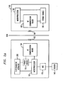
- Figure 2a is a schematic diagram of the implantable shunt apparatus and external controller in the system of Figure 1 in accordance with the present invention
- Figures 2b and 2c are partial cross-sectional views of the electrokinetic actuator of Figure 2a , wherein Figure 2b depicts the electrokinetic actuator at an initial start position and Figure 2c depicts the electrokinetic actuator at a final position when the actuator pin is displaced due to the application of an electric field;
- Figures 3a & 3b are schematic diagrams of a combination rotational and translational mechanical valve actuation mechanism for the electrokinetic actuator of Figure 2a , wherein the mechanical valve actuation mechanism is a rack-n-pinion system in combination with a coil-spring rotating in a clockwise and counter-clockwise direction, respectively;
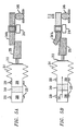
- Figures 4a & b are schematic diagrams of a translational mechanical valve actuation mechanism for the electrokinetic actuator of Figure 2a , wherein the mechanical valve actuation mechanism is a bias-spring, wherein an initial starting position in which the bias-spring is subject to minimum force from the actuator pin is depicted in Figure 4a , while a final position subject to maximum force in the presence of an applied electric field is depicted in Figure 4b ;
- Figures 5a & b are schematic diagrams of a translational mechanical valve actuation mechanism for the electrokinetic actuator of Figure 2a , wherein the mechanical valve actuation mechanism is a combination of a bias-spring and an increasing slope wedge member, wherein an initial start position in which the bias-spring is subject to minimum force from the wedge member is depicted in Figure 5a , while a final position subject to maximum force in the presence of an applied electric field is depicted in Figure 5b ; and
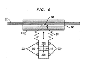
- Figure 6 is a schematic diagram of an electrokinetic actuator wherein the mechanical valve actuation mechanism is a constrictor block and hemispherical constrictor for compressing a flexible tubing through which fluid flows.
- FIG. 1 is an exemplary system 100 including an implantable shunt apparatus 105 implanted within a hydrocephalus patient 110.
- Shunt apparatus 105 includes a proximal, head or ventricular catheter 115 installed in a ventricular cavity 120 of the patient 110, and a distal, peritoneum or drainage catheter 125 disposed in the peritoneum 130 of the patient 110.
- Extending between the ventricular and drainage catheters 115, 125 is a programmable valve apparatus 135 for regulating the flow of CSF into and out of the ventricular cavity 120 of the patient 110.
- the programmable valve apparatus 135 may be disposed anywhere along the fluid pathway of the proximal catheter 115, the distal catheter 125 or therebetween.
- programmable valve apparatus 135 is located within the peritoneal cavity of the patient 110, as illustrated in Figure 1 , so that size constraints for the programmable valve apparatus 135 are minimized (e.g., larger valves can be implanted within the peritoneum than adjacent to the skull).
- One or more sensor elements 140 may be used to measure or detect a physiological characteristic of the patient.
- the single sensor element 140 depicted in Figure 1 may be a volume sensor for detecting volumetric variations within the ventricular cavity or the ventricular catheter of the patient.
- Sensor element 140 may be coupled to the programmable valve apparatus 135, or it may be separate therefrom, as shown in Figure 1 .
- sensor element 140 may be disposed outside of the CSF fluid pathway while still residing within the ventricular cavity 120 of the patient 110.
- the sensor element 140 may be eliminated entirely, if desired.
- System 100 further includes an external controller 145 to communicate data to and from the implantable shunt apparatus 105 when the external controller is positioned proximate the patient and the shunt apparatus is energized.
- external controller 145 may be configured to energize and receive an input signal generated from the sensor element 140 that is representative of the measured value of the physiological characteristic.
- sensor element 140 is a volume sensor and the physiological characteristic is a measured volume of the ventricular cavity 120 of the patient 110.
- Sensor element 140 may measure the volume of fluid flowing through the shunt to monitor proper functioning of the shunt in order to detect a blockage.
- sensor element 140 may be used to determine the drained volume. This determination of drained volume will disadvantageously consume a significant amount of power.
- External controller 145 may be configured to generate and transmit to the programmable valve apparatus 135 a control signal that commands the valve to adjust its pressure.
- the external controller 145 preferably communicates with the implantable shunt wirelessly, e.g., via RF communication.
- Implantable shunt apparatus 105 may include more than one sensor element 140 for measuring an additional physiological characteristic of the patient.
- a second sensor 150 may be a pressure sensor for detecting the ventricular pressure of the patient.
- additional sensor elements transmit data representing a measured or detected value of the additional physiological characteristic to the external controller 145.
- any additional sensors may either be coupled to the valve 135 or be separate therefrom.
- Implantable shunt apparatus 105 and external controller 145 of the present invention are equipped with electronic circuitry similar to those for medical telemetry systems that communicate physiological data (e.g., temperature, pressure, etc.) between an implant and a receiver unit.
- sensor element 140 may be configured to generate an analog signal that is received by the implantable shunt apparatus 105 and converted electronically to a digital pulse.
- the digital pulse is transmitted from the implantable shunt apparatus 105 to the external controller 145 wirelessly such as by radiofrequency (RF) communication.
- RF radiofrequency
- any control signal may be processed by the implantable medical device 105 itself using microprocessor 165.
- RF radiofrequency
- Implantable shunt apparatus 105 has an associated secondary coil 155, RF communication block 160 and microprocessor 165.
- RF communication block 160 transmits/receives and respectively modulates/demodulates the RF data signals.
- Internal power source 170 such as a primary battery, smart rechargeable battery or a super capacitor is used to power the implantable medical device 105 and all components and circuitry associated therewith.
- An analog-to-digital converter (ADC) 175 converts the analog signal generated by the senor element 140 to a digital signal prior to being processed by the microprocessor 165. Only a single sensor element 140 is shown, however, more than one sensor element may be employed to gather information regarding a physiological characteristic or the sensor element may be eliminated.
- External controller 145 includes a primary coil 180 electrically connected to an RF communication block 185 that transmits/receives and respectively modulates the RF data signals.
- the output of the RF communication block 185 is connected to a microprocessor 190.
- All components and circuitry associated with the external controller 145 are powered by a power source 195, e.g., a battery or super capacitor.
- the power source 195 for powering the external device 145 and its associated circuitry and components is a secondary/rechargeable battery, most preferably a smart rechargeable battery, or a super capacitor.
- Microprocessor 190 of external controller 145 compares the measured physiological characteristic (e.g., measured volume detected by sensor element 140) to a predetermined target or reference value (e.g., target or reference volume) for the patient 110.
- the predetermined target value may be ascertained through clinical assessment of the patient 110 and is therefore preferably customized for each particular patient. This target value is then preset or programmed into a memory associated with the external controller 145.
- the external controller 145 energizes the implantable shunt apparatus 105 and detects the measured value of the physiological characteristic detected or measured by sensor element 140.
- Microprocessor 190 associated with external controller 145 determines whether the measured physiological characteristic value is higher than, lower than, or within an acceptable range of the target value.
- the microprocessor 190 determines whether the opening pressure and/or internal diameter or circumference of the shunt and flow rate of fluid passing therethrough should be increased, decreased or maintained accordingly in order to achieve the target ventricular volume for the patient 110. Once again, such functionality may alternatively be performed in a closed loop manner by the microprocessor 165 of the implantable medical device 105. For instance, the rate of fluid flow or drainage is increased if the measured volume is higher than the target volume; conversely, the flow rate and internal diameter of the shunt is decreased if the measured volume is lower than the target volume. The microprocessor 190 generates an output control signal to control the flow rate of the valve by altering the opening pressure and/or the opening, size, diameter or circumference of the shunt itself. If the measured volume is essentially the same as, or within an acceptable range of the target value, then no adjustment is made.
- Electrokinetic actuator 200 is used to convert electric potential to a movement or a force that may be used to adjust the valve 135 that controls the drainage rate through the shunt.
- a basic configuration of the electrokinetic actuator 200 is depicted in Figures 2b & 2c .
- Electrokinetic actuator 200 has two chambers 208, 209 separated by a porous dielectric 210. Chamber 209 is connected to one end of a bellows 211 capable of expanding and collapsing.
- a linearly displaceable actuator pin 212 is disposed at the opposite end of the bellows 211.
- Polar electrolyte 215 passes from chamber 208 to chamber 209 via the porous dielectric 210 upon the application of an electric field or potential to spaced-electrodes or electrode-arrays 220.
- the porous dielectric 210 may include non-porous particles, high surface area structures fabricated within the channel, or microporous such as monolithic polymer networks. Porous dielectric 210 offers at a minimum significant resistance or may prevent the polar electrolyte 215 from moving from one chamber to the other naturally in the absence of an electric field or potential.
- the electrokinetic actuator is biased to apply a minimum pressure or force even in the start position depicted in Figure 2b .
- Figure 2c when an electric field or potential is applied across the electrodes 220, the polar electrolyte 215 is driven from chamber 208 to 209 due to electro-osmotic flow.
- This movement of polar electrolyte 215 expands the bellows 211 attached to chamber 209 with a pressure corresponding to Darcy permeability of the porous dielectric 210 and also the volume of the chamber 209 and the attached bellows 211.
- the displacement of the bellows 211 and the actuator pin 212 with the associated pressure supporting it is utilized as the actuation mechanism for controlling the valve mechanism 135 that controls fluid flow in a shunt.
- Pump performance in terms of pressure generated per volt of applied electric potential is determined by any one or more of several factors including composition of the porous dielectric material, the composition of the stationary phase and geometry as well as the properties of the electrolyte.
- the electrokinetic actuator 200 includes a mechanical valve actuation mechanism to titrate or adjust the pressure at which the fluid pathway will open or even the size of the fluidic pathway itself.
- the mechanical valve actuation mechanism is the bellows 211 and actuator pin 212.
- FIGs 3a, 3b , 4a, 4b , 5a, 5b and 6 Several alternative more complex mechanical valve actuation mechanisms exhibiting rotation, translation or a combination thereof are shown in Figures 3a, 3b , 4a, 4b , 5a, 5b and 6 , however, different mechanical valve actuation mechanisms are contemplated and within the intended scope of the present invention. A brief description of each of the mechanical valve actuation mechanisms is provided below.
- Figures 3a & 3b shows a mechanical valve actuation mechanism including a rack-n-pinion gear in combination with a coil-spring and a linear extension or bias plate 241a.
- Rack and pinion gear converts or translates rotation into linear motion or vice-versa.
- the relatively flat, toothed part is the rack 230 and the gear 235 is the pinion.
- Rack 230 and pinion gear 235 each have formed or cut therein complementary teeth which mesh or engage with one another.
- the speed with which the pinion gear turns as the rack advances or retreats is determined by the diameter of the pinion gear and geometric ratios of the teeth.
- Pinion gear 235 is connected to one end of a coil-spring 240 while the opposite end of the coil-spring 240 is connected to a proximal end of a bias plate 241a.
- An opposite distal end of the bias plate 241a is affixed, fastened or secured to the valve mechanism 245 such as a ball-socket valve.
- Bias plate 241a is supported and held fixed by a guide/fulcrum 216.
- an electric field is applied via a power source 170 to electrodes 220 producing an electro-osmotic force that moves electrolyte 215 from chamber 208 towards chamber 209 thereby expanding the bellows 211 and displacing the actuator pin 212 which, in turn, pushes the proximal end of the rack 230 causing it to move to the right and rotate pinion gear 235 clock-wise, as depicted in Figure 3a .
- Rotation of pinion gear 235 applies tension on the coil-spring 240 causing it to apply increased pressure via the bias plate 241a on the valve mechanism 245 thereby restricting fluid flow. This increase in pressure on the valve mechanism 245 will increase the resistance on the valve mechanism opening and thereby decreasing the rate of drainage.
- This collapse or reverse movement will also be aided by the energy stored within the coil-spring 240.
- the release in energy from the coil-spring 240 will, in turn, reduce the pressure applied by the bias plate 241a on the valve mechanism 245 decreasing the resistance at the valve mechanism opening and thereby increasing the rate of drainage.
- FIG. 4a & 4b An alternative embodiment of a translational mechanical valve actuation mechanism is shown in Figures 4a & 4b wherein the bellows 211 is in contact with an actuator pin 212 which, in turn, is in contact with, a proximal end of a bias-spring 241b whereas its opposite distal end is affixed, fastened or secured to the valve mechanism 245 such as a ball-socket valve.
- an electric field is applied via a power source 170 to electrodes 220 producing an electro-osmotic force that moves electrolyte 215 from chamber 208 towards chamber 209 thereby expanding the bellows 211 which, in turn, displaces actuator pin 212 that pushes against a proximal end of a bias-spring 241b causing it to deflect, as depicted in Figure 4b .
- a counterbalancing force will thereby be created on the opposite distal end of the bias-spring 241b that increases the pressure on the valve mechanism 245 correspondingly increasing the resistance to opening and thereby decreasing the rate of drainage.
- This reverse movement will also be aided by the energy stored within the bias-spring 241b.
- the release in energy from the bias-spring 241b will, in turn, reduce the pressure applied on the valve mechanism 245 thereby decreasing the resistance to opening of the valve mechanism 245 and increasing the rate of drainage.
- FIG. 5a & 5b Still another embodiment of a translational mechanical valve driving mechanism is shown in Figures 5a & 5b , wherein one end of the bellows 211 is in contact with the actuator pin 212 while the opposite end of the actuator pin is in contact with an increasing slope wedge member 255 that moves under the bias-spring 241b affixed, fastened or secured to the valve mechanism 245 such as a ball-socket valve.
- an electric field is applied via a power source 170 to electrodes 220 producing an electro-osmotic force that moves electrolyte 215 from chamber 208 towards chamber 209 thereby expanding the bellows 211 and displacing the actuator pin 212 and wedge 255 to the right, as shown in Figure 5b .
- the wedge 255 Since the wedge 255 has an increasing slope with its widest part at its proximal end that is connected to the actuator pin, displacement of the wedge 255 pushes the proximal end of the bias-spring 241b upward causing the energy contained within it to increase. This increase in energy will result in increased pressure on the valve mechanism 245 and thus increase the resistance to opening; thereby decreasing the rate of drainage.
- All embodiments of the mechanical valve actuator mechanism described above may not only finely titrate the fluid flow therethrough but are also adapted to permit full fluid flow or cease or close off completely all fluid flow.
- the flexible tubing 275 in which drainage of the fluid therethrough is to be controlled or regulated is received within a channel 243 of a constrictor block 241c.
- One side of constrictor block 241c is preferably connected directly to one end of the bellows 211 thereby eliminating the actuator pin 212 in order to maximize the surface area of contact.
- a constrictor 242, preferably hemispherical in shape, is disposed within the channel 243 between the flexible tubing 275 and the side of the constrictor block 241c connected to the bellows 211.
- the constrictor 242 and constrictor block 241c are preferably made from a magnetic resonance imaging (MRI) compatible thermoset polymer, glass, natural stone (e.g., ruby), hardened metal or alloy. Materials used for the constrictor 242 and constrictor block 241c may be the same or different.
- Constrictor 242 pushes against the flexible tubing 275 made of a biocompatible flexible and elastic material, for example, silicone or polyurethane.
- an electric field is applied via a power source 170 to electrodes 220 producing an electro-osmotic force that moves electrolyte 215 from chamber 208 towards chamber 209 thereby expanding the bellows 211 which, in turn, pushes the constrictor block 241c upward.
- constrictor block 241c and constrictor 242 imposes a force against flexible tubing 275 causing it to deform and thereby restricting the cross-sectional size of the passage available for the fluid to drain therethrough.
- the preferred hemispherical shape of constrictor 242 distributes the pressure more gradually than a sharp edge and minimizes any damage to the flexible tubing with long-term operation.
- the electric field applied via the power source 170 to the electrodes 220 may be reversed producing an electro-osmotic force that moves electrolyte 215 from chamber 209 towards chamber 208 thereby causing the bellows 211 to collapse and reduce the pressure applied by the constrictor 242 on the flexible tubing 275 which will result in decreasing the resistance at the opening of valve member 245 and thereby increasing the rate of drainage.
- the embodiment depicted in Figure 6 of the present invention is adapted to finely titrate or full fluid flow rather than close off fluid passage completely.
- the present inventive electrokinetic actuator is not limited to only those mechanical value actuation mechanisms expressly disclosed and illustrated herein. Furthermore, the present inventive electrokinetic actuator to finely titrate fluid flow has been described with respect to a particular application of use with an externally programmable implantable shunt system for draining CSF. Other medical uses both implanted and external to the body as well as non-medical applications are contemplated and within the intended scope of the present invention.
Landscapes
- Health & Medical Sciences (AREA)
- Engineering & Computer Science (AREA)
- Biomedical Technology (AREA)
- Neurology (AREA)
- Ophthalmology & Optometry (AREA)
- Otolaryngology (AREA)
- Anesthesiology (AREA)
- Heart & Thoracic Surgery (AREA)
- Hematology (AREA)
- Life Sciences & Earth Sciences (AREA)
- Animal Behavior & Ethology (AREA)
- General Health & Medical Sciences (AREA)
- Public Health (AREA)
- Veterinary Medicine (AREA)
- External Artificial Organs (AREA)
Claims (19)
- Elektrokinetischer Aktuator (200) zur Titration eines Flüssigkeitsstroms mit:einer ersten Kammer (208), die ein geschlossenes proximales Ende und ein gegenüberliegendes offenes distales Ende aufweist;einer zweiten Kammer (209), die ein offenes proximales Ende und ein gegenüberliegendes offenes distales Ende aufweist, wobei das offene distale Ende der ersten Kammer (208) von dem offenen proximalen Ende der zweiten Kammer (209) durch ein poröses Dielektrikum (210) abgetrennt ist, das dazwischen angeordnet ist;mehreren Elektroden (220), die über einen Umfang der ersten und zweiten Kammer hinweg angeordnet sind; undeinem polaren Elektrolyt (215), der im Aktuator angeordnet und geeignet ist, beim Anlegen eines elektrischen Feldes oder elektrischen Potenzials an die mehreren Elektroden durch das poröse Dielektrikum (210) zwischen der ersten (208) und zweiten Kammer (209) hindurchzutreten; undeinem mechanischen Ventilbetätigungsmechanismus, der an das offene distale Ende der zweiten Kammer (209) zur Feintitration einer Flüssigkeit angeschlossen ist, wobei die Elektroosmose des polaren Elektrolyts verwendet wird, das isoliert ist, um ein Vermischen mit einer zu titrierenden Flüssigkeit zu verhindern;dadurch gekennzeichnet, dass der mechanische Ventilbetätigungsmechanismus aufweist:einen Faltenbalg (211) mit einem offenen proximalen Ende und einem gegenüberliegenden distalen Ende, wobei das offene proximale Ende des Faltenbalgs an das offene distale Ende der zweiten Kammer (209) angeschlossen ist;einen Aktuatorstift (212) mit einem proximalen Ende, der so angeschlossen ist, dass er das offene distale Ende des Faltenbalgs (211) verschließt, und mit einem gegenüberliegenden distalen Ende;eine Zahnstange (230), die an das distale Ende des Aktuatorstifts (212) angeschlossen ist, wobei die Zahnstange (230) mehrere Zähne aufweist;ein Ritzel (235), das darauf abgestimmte Zähne aufweist und so angeordnet ist, dass es in die Zähne der Zahnstange (230) eingreift;eine Spiralfeder (240), die mit einem ersten Ende des Ritzels (235) verbunden ist und ein gegenüberliegendes zweites Ende aufweist;eine Vorspannplatte (241a), die an einem proximalen Ende mit dem zweiten Ende der Spiralfeder (240) verbunden ist, und ein gegenüberliegendes distales Ende, wobei die Vorspannplatte (241a) durch eine Abstützung unterstützt und festgehalten wird.
- Elektrokinetischer Aktuator (200) zur Titration eines Flüssigkeitsstroms mit:einer ersten Kammer (208), die ein geschlossenes proximales Ende und ein gegenüberliegendes offenes distales Ende aufweist;einer zweiten Kammer (209), die ein offenes proximales Ende und ein gegenüberliegendes offenes distales Ende aufweist, wobei das offene distale Ende der ersten Kammer (208) von dem offenen proximalen Ende der zweiten Kammer (209) durch ein poröses Dielektrikum (210) abgetrennt ist, das dazwischen angeordnet ist;mehreren Elektroden (220), die über einen Umfang der ersten und zweiten Kammer hinweg angeordnet sind; undeinem polaren Elektrolyt (215), der im Aktuator angeordnet und geeignet ist, beim Anlegen eines elektrischen Feldes oder elektrischen Potenzials an die mehreren Elektroden durch das poröse Dielektrikum (210) zwischen der ersten (208) undzweiten Kammer (209) hindurchzutreten; undeinem mechanischen Ventilbetätigungsmechanismus,der an das offene distale Ende der zweiten Kammer (209) zur Feintitration einer Flüssigkeit angeschlossen ist, wobei die Elektroosmose des polaren Elektrolyts verwendet wird, das isoliert ist, um ein Vermischen mit einer zu titrierenden Flüssigkeit zu verhindern;dadurch gekennzeichnet, dass der mechanische Ventilbetätigungsmechanismus aufweist:einen Faltenbalg (211) mit einem offenen proximalen Ende und einem gegenüberliegenden distalen Ende, wobei das offene proximale Ende des Faltenbalgs an das offene distale Ende der zweiten Kammer (209) angeschlossen ist;einen Aktuatorstift (230) mit einem proximalen Ende und einem gegenüberliegenden distalen Ende,wobei das proximale Ende des Aktuatorstifts so angeschlossen ist, dass er das distale Ende des Faltenbalgs (211) verschließt;eine Vorspannfeder (241b), die an einem proximalen Ende mit dem distalen Ende des Aktuatorstifts (230) verbunden ist, und die ein gegenüberliegendes distales Ende aufweist, wobei die Vorspannfeder durch eine Abstützung unterstützt und festgehalten wird, wobei das proximale Ende der Vorspannfeder (241b) in Reaktion auf den Übergang des Elektrolyts aus der ersten Kammer (208) in die zweite Kammer (209) beim Anlegen eines elektrischen Feldes an die mehreren Elektroden (220) verformbar ist.
- Elektrokinetischer Aktuator nach Anspruch 1 oder Anspruch 2, wobei das distale Ende der Vorspannplatte mit einem Ventilmechanismus verbunden ist, um eine Öffnung davon einzustellen.
- Elektrokinetischer Aktuator (200) zur Titration eines Flüssigkeitsstromes mit:einer ersten Kammer (208), die ein geschlossenes proximales Ende und ein gegenüberliegendes offenes distales Ende aufweist;einer zweiten Kammer (209), die ein offenes proximales Ende und ein gegenüberliegendes offenes distales Ende aufweist, wobei das offene distale Ende der ersten Kammer (208) von dem offenen proximalen Ende der zweiten Kammer (209) durch ein poröses Dielektrikum (210) abgetrennt ist, das dazwischen angeordnet ist;mehreren Elektroden (220), die über einen Umfang der ersten und zweiten Kammer hinweg angeordnet sind; undeinem polaren Elektrolyt (215), der im Aktuator angeordnet und geeignet ist, beim Anlegen eines elektrischen Feldes oder elektrischen Potenzials an die mehreren Elektroden durch das poröse Dielektrikum (210) zwischen der ersten (208) und zweiten Kammer (209) hindurchzutreten; undeinem mechanischen Ventilbetätigungsmechanismus, der an das offene distale Ende der zweiten Kammer (209) zur Feintitration einer Flüssigkeit angeschlossen ist, wobei die Elektroosmose des polaren Elektrolyts verwendet wird, das isoliert ist, um ein Vermischen mit einer zu titrierenden Flüssigkeit zu verhindern;dadurch gekennzeichnet, dass der mechanische Ventilbetätigungsmechanismus aufweist:einen Faltenbalg (211) mit einem offenen proximalen Ende und einem gegenüberliegenden distalen Ende, wobei das offene proximale Ende des Faltenbalgs an das offene distale Ende der zweiten Kammer (209) angeschlossen ist;einen Aktuatorstift (230) mit einem proximalen Ende und einem distalen Ende, wobei das proximale Ende des Aktuatorstifts so angeschlossen ist, dass er das distale Ende des Faltenbalgs (211) verschließt;ein Keilbauteil (255) mit ansteigender Flanke, das ein schmaleres distales Ende und ein gegenüberliegendes größeres proximales Ende aufweist, das mit dem distalen Ende des Aktuatorstifts (230) verbunden ist;eine Vorspannfeder (241b) mit einem proximalen Ende, das durch das distale Ende des Keilbauteils (255) unterstützt wird, und einem gegenüberliegenden distalen Ende, wobei die Vorspannfeder durch eine Abstützung unterstützt und festgehalten wird.
- Elektrokinetischer Aktuator nach Anspruch 4, wobei das distale Ende der Vorspannfeder mit einem Ventilmechanismus verbunden ist, um eine Öffnung davon einzustellen.
- Elektrokinetischer Aktuator (200) zur Titration eines Flüssigkeitsstromes mit:einer ersten Kammer (208), die ein geschlossenes proximales Ende und ein gegenüberliegendes offenes distales Ende aufweist;einer zweiten Kammer (209), die ein offenes proximales Ende und ein gegenüberliegendes offenes distales Ende aufweist, wobei das offene distale Ende der ersten Kammer (208) von dem offenen proximalen Ende der zweiten Kammer (209) durch ein poröses Dielektrikum (210) abgetrennt ist, das dazwischen angeordnet ist;mehreren Elektroden (220), die über einen Umfang der ersten und zweiten Kammer hinweg angeordnet sind; undeinem polaren Elektrolyt (215), der im Aktuator angeordnet und geeignet ist, beim Anlegen eines elektrischen Feldes oder elektrischen Potenzials an die mehreren Elektroden durch das poröse Dielektrikum (210) zwischen der ersten (208) undzweiten Kammer (209) hindurchzutreten; undeinem mechanischen Ventilbetätigungsmechanismus,der an das offene distale Ende der zweiten Kammer (209) zur Feintitration einer Flüssigkeit angeschlossen ist, wobei die Elektroosmose des polaren Elektrolyts verwendet wird, das isoliert ist, um ein Vermischen mit einer zu titrierenden Flüssigkeit zu verhindern;dadurch gekennzeichnet, dass der mechanische Ventilbetätigungsmechanismus aufweist:einen Faltenbalg (211) mit einem offenen proximalen Ende und einem gegenüberliegenden offenen distalen Ende, wobei das offene proximale Ende des Faltenbalgs an das offene distale Ende der zweiten Kammer (209) angeschlossen ist;einen Einschnürungsblock (241c), der einen Kanal (243) aufweist, der dort längs hindurchgehend festgelegt ist, um ein flexibles und elastisches Rohr (275) aufzunehmen, wobei das offene distale Ende des Faltenbalgs (211) an einem Umfang des Einschnürungsblock (241c) angeschlossen ist;ein Einschnürungsbauteil (242), das in dem Kanal (243) zwischen dem Rohr (275) und dem Einschnürungsblock (241c) angeordnet ist, der an den Faltenbalg (211) angeschlossen ist.
- Elektrokinetischer Aktuator nach einem der vorhergehenden Ansprüche, wobei der Aktuator eine hydraulische Kraft von weniger als circa 500 mbar ausübt.
- Elektrokinetischer Aktuator nach einem der vorhergehenden Ansprüche, wobei die Feintitration des Flüssigkeitsstroms, die durch den mechanischen Aktuatormechanismus bewirkt wird, nicht nur auf die zwei Stromzustände mit uneingeschränktem Flüssigkeitsstrom und vollständig unterbrochenen Flüssigkeitsstrom beschränkt ist.
- Elektrokinetischer Aktuator nach Anspruch 6, wobei der mechanische Betätigungsmechanismus nicht ein vollständiges Unterbrechen des Flüssigkeitsstroms erlaubt.
- Verfahren für die Feintitration eines Flüssigkeitsstroms unter Verwendung des elektrokinetischen Aktuators nach einem der Ansprüche 1 bis 9, die Schritte umfassend zum:Ausüben einer mechanischen Kraft über den mechanischen Ventilbetätigungsmechanismus auf eine Öffnung eines Ventilbauteils, um einen Flüssigkeitsstrom dort hindurch einzustellen.
- Verfahren nach Anspruch 10, wobei der Anwendungsschritt die Schritte umfasst zum:Anlegen eines elektrischen Potenzials oder elektrischen Feldes an mehrere Elektroden, um eine Elektroosmose hervorzurufen, die den Elektrolyt zwischen den zwei Kammern durch das poröse Dielektrikum hindurch verschiebt;Expandieren/Kontraktion des Faltenbalgs, der an die zweite Kammer angeschlossen ist, als Ergebnis der Elektroosmose des Elektrolyts;linearen Verschieben des Aktuatorstifts, der mit dem Faltenbalg verbunden ist, im Ergebnis der Expansion/Kontraktion des Faltenbalgs;Einstellen einer Kraft, die auf die Öffnung des Ventilbauteils ausgeübt wird, auf Basis der linearen Verschiebung des Aktuatorstifts.
- Verfahren nach Anspruch 11 unter Verwendung des Aktuators von Anspruch 1, wobei der Krafteinstellungsschritt die Schritte umfasst zum:linearen Verschieben der Zahnstange, die an den Aktuatorstift angeschlossen ist;Eingreifen der mehreren Zähne der Zahnstange in die darauf abgestimmten Zähne des Ritzels, um so die Spiralfeder zu drehen und die Spannung der Spiralfeder zu steuern;Verschieben der Vorspannplatte nach oben/unten, die durch eine Abstützung unterstützt und festgehalten wird und die mit einem Ende der Spiralfeder verbunden ist, wobei ein gegenüberliegendes Ende der Vorspannplatte mit der Öffnung des Ventilbauteils verbunden ist, damit der Flüssigkeitsstrom dort hindurch fein titriert wird;wobei die Drehung des Ritzels im Uhrzeigersinn die Spannung in der Spiralfeder erhöht, was die Öffnung des Ventilmechanismus verringert, und wobei das Drehen des Ritzels gegen den Uhrzeigersinn die Spannung in der Spiralfeder verringert, was die Öffnung des Ventilmechanismus vergrößert.
- Verfahren nach Anspruch 11 unter Verwendung des Aktuators von Anspruch 2, wobei der Krafteinstellungsschritt die Schritte umfasst zum:Auslenken eines proximalen Endes der Vorspannfeder, die mit dem Aktuatorstift verbunden ist, nach oben/unten, wobei die Vorspannfeder durch die Abstützung unterstützt und festgehalten wird und wobei ein distales Ende der Vorspannfeder mit der Öffnung des Ventilbauteils verbunden ist,damit der Flüssigkeitsstrom dort hindurch fein titriert wird;wobei das Auslenken des proximalen Endes der Vorspannfeder nach oben eine ausgleichende Gegenkraft am distalen Ende der Vorspannfeder erzeugt, welche die Öffnung des Ventilmechanismus verkleinert, was den Flüssigkeitsstrom dort hindurch verringert, und wobei eine verringerte Auslenkung des proximalen Endes der Vorspannfeder die ausgleichende Gegenkraft am distalen Ende der Vorspannfeder verringert, sodass die Öffnung des Ventilmechanismus vergrößert wird, was den Flüssigkeitsstrom dort hindurch erhöht.
- Verfahren nach Anspruch 11 unter Verwendung des Aktuators von Anspruch 4, wobei der Einstellungsschritt die Schritte umfasst zum:linearen Verschieben des Keilbauteils, das an seinem proximalen Ende eine ansteigende Flanke mit einer maximalen Breite aufweist, das mit dem Aktuatorstift verbunden ist, und das an seinem distalen Ende eine minimale Breite aufweist;Auslenken eines proximalen Endes der Vorspannfeder, die durch das distale Ende des Keilbauteils unterstützt wird, nach oben/unten,wobei die Vorspannfeder durch die Abstützung unterstützt und festgehalten wird und wobei ein distales Ende der Vorspannfeder mit der Öffnung des Ventilbauteils verbunden ist, damit der Flüssigkeitsstrom dort hindurch eingestellt wird;wobei das Auslenken des proximalen Endes der Vorspannfeder nach oben eine ausgleichende Gegenkraft am distalen Ende der Vorspannfeder erzeugt, welche die Öffnung des Ventilmechanismus verkleinert, was den Flüssigkeitsstrom dort hindurch verringert, und wobei eine verringerte Auslenkung des proximalen Endes der Vorspannfeder die ausgleichende Gegenkraft am distalen Ende der Vorspannfeder verringert, sodass die Öffnung des Ventilmechanismus vergrößert wird, was den Flüssigkeitsstrom dort hindurch erhöht.
- Verfahren nach Anspruch 10, wobei der Ausübungsschritt die Schritte umfasst zum:Anlegen eines elektrischen Potenzials oderelektrischen Feldes an mehrere Elektroden, um eine Elektroosmose hervorzurufen, die den Elektrolyt zwischen den zwei Kammern durch das poröse Dielektrikum hindurch verschiebt;Expandieren/Kontraktion des Faltenbalgs, der an die zweite Kammer angeschlossen ist, als Ergebnis der Verschiebung des Elektrolyts;Einstellen einer Kraft, die auf ein flexibles Rohr ausgeübt wird, durch welches hindurch die Flüssigkeit strömt, wodurch eine Querschnittsfläche des flexiblen Rohrs verformt wird.
- Verfahren nach Anspruch 15 unter Verwendung des Aktuators von Anspruch 6, wobei der Krafteinstellungsschritt die Schritte umfasst zum:Ausüben einer Kraft auf den Einschnürungsblock,der über einem Umfang des flexiblen Rohrs angeordnet ist, wobei der Einschnürungsblock einen Längskanal aufweist, der dort hindurch festgelegt ist;Einpressen des Einschnürungsbauteils in das flexible Rohr, sodass die Querschnittsfläche des flexiblen Rohrs geändert wird, wobei das Einschnürungsbauteil in dem Kanal zwischen dem flexiblen Rohr und einem Teil des Einschnürungsblocks angeordnet ist, der dem Faltenbalg benachbart ist.
- Verfahren nach Anspruch 16, wobei das Einschnürungsbauteil halbkugelförmig ist.
- Implantierbares Shunt-System mit:einem proximalen Katheter;einem Drainagekatheter;einer Ventilvorrichtung, die zwischen dem proximalen und Drainagekatheter angeordnet ist;undeinem elektrokinetischen Aktuator nach einem der Ansprüche 1 bis 9, um zerebrospinale Flüssigkeit aus dem proximalen Katheter zum Drainagekatheter fein zu titrieren, indem ein Öffnungsdruck und/oder Durchmesser der Ventilvorrichtung gesteuert wird, wobei die Feintitration einen uneingeschränkten Flüssigkeitsstrom und/oder einen vollständig unterbrochenen Flüssigkeitsstrom einschließt.
- Drainagesystem mit:einem proximalen Katheter;einem Drainagekatheter;einer Ventilvorrichtung, die zwischen dem proximalen und Drainagekatheter angeordnet ist;undeinem elektrokinetischen Aktuator nach einem der Ansprüche 1 bis 9, um Flüssigkeit aus dem proximalen Katheter zum Drainagekatheter fein zu titrieren, indem ein Öffnungsdruck und/oder Durchmesser der Ventilvorrichtung gesteuert wird,wobei die Feintitration einen uneingeschränkten Flüssigkeitsstrom und/oder einen vollständig unterbrochenen Flüssigkeitsstrom einschließt.
Applications Claiming Priority (1)
| Application Number | Priority Date | Filing Date | Title |
|---|---|---|---|
| US12/655,404 US8231563B2 (en) | 2009-12-30 | 2009-12-30 | Electrokinetic actuator to titrate fluid flow |
Publications (3)
| Publication Number | Publication Date |
|---|---|
| EP2366423A2 EP2366423A2 (de) | 2011-09-21 |
| EP2366423A3 EP2366423A3 (de) | 2012-05-16 |
| EP2366423B1 true EP2366423B1 (de) | 2014-08-20 |
Family
ID=44188386
Family Applications (1)
| Application Number | Title | Priority Date | Filing Date |
|---|---|---|---|
| EP10252240.6A Not-in-force EP2366423B1 (de) | 2009-12-30 | 2010-12-29 | Elektrokinetischer Aktuator zur Flüssigkeitsstromtitrierung |
Country Status (6)
| Country | Link |
|---|---|
| US (2) | US8231563B2 (de) |
| EP (1) | EP2366423B1 (de) |
| JP (1) | JP5863238B2 (de) |
| AU (1) | AU2010266095A1 (de) |
| CA (1) | CA2726339A1 (de) |
| CO (1) | CO6300126A1 (de) |
Families Citing this family (29)
| Publication number | Priority date | Publication date | Assignee | Title |
|---|---|---|---|---|
| US8577469B2 (en) | 2006-07-12 | 2013-11-05 | Rainbow Medical Ltd. | Iontophoretic and electroosmotic disc treatment |
| US9731122B2 (en) * | 2013-04-29 | 2017-08-15 | Rainbow Medical Ltd. | Electroosmotic tissue treatment |
| MX2017009336A (es) | 2015-01-16 | 2017-11-15 | Voyager Therapeutics Inc | Polinucleótidos dirigidos al sistema nervioso central. |
| US9616221B2 (en) | 2015-07-08 | 2017-04-11 | Rainbow Medical Ltd. | Electrical treatment of Alzheimer's disease |
| CN105126228B (zh) * | 2015-10-21 | 2019-09-13 | 迟金亭 | 一种智能中医肾病治疗仪 |
| US10898716B2 (en) | 2015-10-29 | 2021-01-26 | Rainbow Medical Ltd. | Electrical substance clearance from the brain |
| US9724515B2 (en) | 2015-10-29 | 2017-08-08 | Rainbow Medical Ltd. | Electrical substance clearance from the brain for treatment of Alzheimer's disease |
| US9950156B2 (en) | 2016-09-13 | 2018-04-24 | Rainbow Medical Ltd. | Disc therapy |
| US9770591B2 (en) | 2015-12-29 | 2017-09-26 | Rainbow Medical Ltd. | Disc therapy |
| US10518085B2 (en) | 2015-12-29 | 2019-12-31 | Rainbow Medical Ltd. | Disc therapy |
| US11484706B2 (en) | 2015-12-29 | 2022-11-01 | Discure Technologies Ltd | Disc therapy |
| US10569086B2 (en) | 2017-01-11 | 2020-02-25 | Rainbow Medical Ltd. | Electrical microglial cell activation |
| US10758722B2 (en) | 2017-05-03 | 2020-09-01 | Rainbow Medical Ltd. | Electrical treatment of Parkinson's disease |
| US11202905B2 (en) | 2018-03-14 | 2021-12-21 | Rainbow Medical Ltd. | Electrical substance clearance from the brain |
| US20210207167A1 (en) | 2018-05-16 | 2021-07-08 | Voyager Therapeutics, Inc. | Aav serotypes for brain specific payload delivery |
| US11548261B2 (en) | 2018-10-24 | 2023-01-10 | Toyota Motor Engineering & Manufacturing North America, Inc. | Structure with selectively variable stiffness |
| US11088635B2 (en) * | 2018-10-25 | 2021-08-10 | Toyota Motor Engineering & Manufacturing North America, Inc. | Actuator with sealable edge region |
| US11498270B2 (en) | 2018-11-21 | 2022-11-15 | Toyota Motor Engineering & Manufacturing North America, Inc. | Programmable matter |
| US11195506B2 (en) | 2018-12-03 | 2021-12-07 | Toyota Motor Engineering & Manufacturing North America, Inc. | Sound-modulating windows |
| US11479308B2 (en) | 2019-01-09 | 2022-10-25 | Toyota Motor Engineering & Manufacturing North America, Inc. | Active vehicle interface for crosswind management |
| US11192469B2 (en) | 2019-01-30 | 2021-12-07 | Toyota Motor Engineering & Manufacturing North America, Inc. | Vehicle seat with morphing bolsters |
| US11473567B2 (en) | 2019-02-07 | 2022-10-18 | Toyota Motor Engineering & Manufacturing North America, Inc. | Programmable surface |
| US11123197B2 (en) | 2019-09-03 | 2021-09-21 | Rainbow Medical Ltd. | Hydropneumatic artificial intervertebral disc |
| US10881858B1 (en) | 2019-09-18 | 2021-01-05 | Rainbow Medical Ltd. | Electrical substance clearance from the brain |
| US11298530B1 (en) | 2021-05-03 | 2022-04-12 | Discure Technologies Ltd. | Synergistic therapies for intervertebral disc degeneration |
| US11344721B1 (en) | 2021-08-16 | 2022-05-31 | Rainbow Medical Ltd. | Cartilage treatment |
| US11413455B1 (en) | 2022-02-08 | 2022-08-16 | Rainbow Medical Ltd. | Electrical treatment of Alzheimer's disease |
| US12208267B1 (en) | 2024-04-19 | 2025-01-28 | Yossi Gross | Blood flow enhancement therapy system |
| SE2450632A1 (en) * | 2024-06-10 | 2025-12-11 | Brain Flow Ab | A medical device for treatment of the central nervous system by inducing and modulating a controlled fluid transport |
Family Cites Families (17)
| Publication number | Priority date | Publication date | Assignee | Title |
|---|---|---|---|---|
| US4595390A (en) * | 1983-07-21 | 1986-06-17 | Salomon Hakim | Magnetically-adjustable cerebrospinal fluid shunt valve |
| US6019882A (en) * | 1997-06-25 | 2000-02-01 | Sandia Corporation | Electrokinetic high pressure hydraulic system |
| US6013164A (en) * | 1997-06-25 | 2000-01-11 | Sandia Corporation | Electokinetic high pressure hydraulic system |
| US6406605B1 (en) * | 1999-06-01 | 2002-06-18 | Ysi Incorporated | Electroosmotic flow controlled microfluidic devices |
| US20020026139A1 (en) * | 2000-02-02 | 2002-02-28 | Bertrand William Jeff | Valve seat and valve |
| JP2002022048A (ja) * | 2000-07-06 | 2002-01-23 | Seiko Instruments Inc | 圧力可変弁装置 |
| US7390310B2 (en) | 2002-07-10 | 2008-06-24 | Codman & Shurtleff, Inc. | Shunt valve locking mechanism |
| US7318813B2 (en) * | 2003-06-26 | 2008-01-15 | Codman & Shurtleff, Inc. | Self adjusting hydrocephalus valve |
| US7217351B2 (en) * | 2003-08-29 | 2007-05-15 | Beta Micropump Partners Llc | Valve for controlling flow of a fluid |
| US20050055009A1 (en) * | 2003-09-05 | 2005-03-10 | Codman & Shurtleff, Inc. | Method and apparatus for managing normal pressure hydrocephalus |
| US7367968B2 (en) * | 2003-09-05 | 2008-05-06 | Codman & Shurtleff, Inc. | Implantable pump with adjustable flow rate |
| US7298246B1 (en) * | 2004-04-15 | 2007-11-20 | Schmitt William J | Vehicle security monitoring device |
| US7297246B2 (en) | 2004-04-22 | 2007-11-20 | Sandia Corporation | Electrokinetic pump |
| JP4328681B2 (ja) * | 2004-07-09 | 2009-09-09 | 株式会社カネカメディックス | 皮下埋設器ユニット |
| JP4328688B2 (ja) * | 2004-07-26 | 2009-09-09 | 株式会社カネカメディックス | 皮下埋設型体液流量調整装置 |
| US7559912B2 (en) | 2004-09-30 | 2009-07-14 | Codman & Shurtleff, Inc. | High pressure range hydrocephalus valve system |
| US8123714B2 (en) * | 2007-06-29 | 2012-02-28 | Codman & Shurtleff, Inc. | Programmable shunt with electromechanical valve actuator |
-
2009
- 2009-12-30 US US12/655,404 patent/US8231563B2/en not_active Expired - Fee Related
-
2010
- 2010-12-22 AU AU2010266095A patent/AU2010266095A1/en not_active Abandoned
- 2010-12-22 CA CA2726339A patent/CA2726339A1/en not_active Abandoned
- 2010-12-28 JP JP2010292105A patent/JP5863238B2/ja not_active Expired - Fee Related
- 2010-12-29 CO CO10164089A patent/CO6300126A1/es active IP Right Grant
- 2010-12-29 EP EP10252240.6A patent/EP2366423B1/de not_active Not-in-force
-
2012
- 2012-07-09 US US13/544,891 patent/US20120323161A1/en not_active Abandoned
Also Published As
| Publication number | Publication date |
|---|---|
| US8231563B2 (en) | 2012-07-31 |
| EP2366423A3 (de) | 2012-05-16 |
| EP2366423A2 (de) | 2011-09-21 |
| CA2726339A1 (en) | 2011-06-30 |
| JP2011136174A (ja) | 2011-07-14 |
| AU2010266095A1 (en) | 2011-07-14 |
| US20110160638A1 (en) | 2011-06-30 |
| US20120323161A1 (en) | 2012-12-20 |
| CO6300126A1 (es) | 2011-07-21 |
| JP5863238B2 (ja) | 2016-02-16 |
Similar Documents
| Publication | Publication Date | Title |
|---|---|---|
| EP2366423B1 (de) | Elektrokinetischer Aktuator zur Flüssigkeitsstromtitrierung | |
| US12427292B2 (en) | Externally programmable valve assembly | |
| EP1512428B1 (de) | Vorrichtung zum Regeln eines Normaldruck-Hydrocephalus | |
| AU2008202818B2 (en) | Programmable shunt with electromechanical valve actuator | |
| US6383160B1 (en) | Variable anti-siphon valve apparatus and method | |
| US7025739B2 (en) | System and method for treating elevated intracranial pressure | |
| EP2432544B1 (de) | Passiver Flüssigkeitsflussregler | |
| US20040068221A1 (en) | Methods for the treatment of a normal pressure hydrocephalus | |
| CN112399827B (zh) | 用于脑积水的治疗 | |
| US8211051B2 (en) | Electroactive polymer actuated cerebrospinal fluid shunt | |
| EP0982048A1 (de) | Implantat zur kontrollierten Ableitung von Gehirnflüssigkeit | |
| EP0135991A1 (de) | Chirurgisch implantierbares Hydrocephalus-Ventil | |
| EP2640454B1 (de) | Elektrisch betätigbares, insbesondere programmierbares hydrocephalus-ventil | |
| US5810761A (en) | Intraventricular pressure control device | |
| AU2013242833B2 (en) | Programmable shunt with electromechanical valve actuator | |
| Aihara et al. | In vitro experiment for verification of the tandem shunt valve system: a novel method for treating hydrocephalus by flexibly controlling cerebrospinal fluid flow and intracranial pressure |
Legal Events
| Date | Code | Title | Description |
|---|---|---|---|
| PUAI | Public reference made under article 153(3) epc to a published international application that has entered the european phase |
Free format text: ORIGINAL CODE: 0009012 |
|
| AK | Designated contracting states |
Kind code of ref document: A2 Designated state(s): AL AT BE BG CH CY CZ DE DK EE ES FI FR GB GR HR HU IE IS IT LI LT LU LV MC MK MT NL NO PL PT RO RS SE SI SK SM TR |
|
| AX | Request for extension of the european patent |
Extension state: BA ME |
|
| PUAL | Search report despatched |
Free format text: ORIGINAL CODE: 0009013 |
|
| AK | Designated contracting states |
Kind code of ref document: A3 Designated state(s): AL AT BE BG CH CY CZ DE DK EE ES FI FR GB GR HR HU IE IS IT LI LT LU LV MC MK MT NL NO PL PT RO RS SE SI SK SM TR |
|
| AX | Request for extension of the european patent |
Extension state: BA ME |
|
| RIC1 | Information provided on ipc code assigned before grant |
Ipc: A61M 27/00 20060101AFI20120412BHEP Ipc: F03G 7/00 20060101ALI20120412BHEP |
|
| 17P | Request for examination filed |
Effective date: 20121116 |
|
| 17Q | First examination report despatched |
Effective date: 20130301 |
|
| GRAP | Despatch of communication of intention to grant a patent |
Free format text: ORIGINAL CODE: EPIDOSNIGR1 |
|
| INTG | Intention to grant announced |
Effective date: 20130627 |
|
| GRAP | Despatch of communication of intention to grant a patent |
Free format text: ORIGINAL CODE: EPIDOSNIGR1 |
|
| INTG | Intention to grant announced |
Effective date: 20131127 |
|
| GRAS | Grant fee paid |
Free format text: ORIGINAL CODE: EPIDOSNIGR3 |
|
| GRAA | (expected) grant |
Free format text: ORIGINAL CODE: 0009210 |
|
| AK | Designated contracting states |
Kind code of ref document: B1 Designated state(s): AL AT BE BG CH CY CZ DE DK EE ES FI FR GB GR HR HU IE IS IT LI LT LU LV MC MK MT NL NO PL PT RO RS SE SI SK SM TR |
|
| REG | Reference to a national code |
Ref country code: GB Ref legal event code: FG4D |
|
| REG | Reference to a national code |
Ref country code: CH Ref legal event code: EP |
|
| REG | Reference to a national code |
Ref country code: AT Ref legal event code: REF Ref document number: 683096 Country of ref document: AT Kind code of ref document: T Effective date: 20140915 |
|
| REG | Reference to a national code |
Ref country code: IE Ref legal event code: FG4D |
|
| REG | Reference to a national code |
Ref country code: DE Ref legal event code: R096 Ref document number: 602010018359 Country of ref document: DE Effective date: 20141002 |
|
| REG | Reference to a national code |
Ref country code: AT Ref legal event code: MK05 Ref document number: 683096 Country of ref document: AT Kind code of ref document: T Effective date: 20140820 |
|
| REG | Reference to a national code |
Ref country code: NL Ref legal event code: VDEP Effective date: 20140820 |
|
| REG | Reference to a national code |
Ref country code: LT Ref legal event code: MG4D |
|
| PG25 | Lapsed in a contracting state [announced via postgrant information from national office to epo] |
Ref country code: PT Free format text: LAPSE BECAUSE OF FAILURE TO SUBMIT A TRANSLATION OF THE DESCRIPTION OR TO PAY THE FEE WITHIN THE PRESCRIBED TIME-LIMIT Effective date: 20141222 Ref country code: FI Free format text: LAPSE BECAUSE OF FAILURE TO SUBMIT A TRANSLATION OF THE DESCRIPTION OR TO PAY THE FEE WITHIN THE PRESCRIBED TIME-LIMIT Effective date: 20140820 Ref country code: NO Free format text: LAPSE BECAUSE OF FAILURE TO SUBMIT A TRANSLATION OF THE DESCRIPTION OR TO PAY THE FEE WITHIN THE PRESCRIBED TIME-LIMIT Effective date: 20141120 Ref country code: ES Free format text: LAPSE BECAUSE OF FAILURE TO SUBMIT A TRANSLATION OF THE DESCRIPTION OR TO PAY THE FEE WITHIN THE PRESCRIBED TIME-LIMIT Effective date: 20140820 Ref country code: GR Free format text: LAPSE BECAUSE OF FAILURE TO SUBMIT A TRANSLATION OF THE DESCRIPTION OR TO PAY THE FEE WITHIN THE PRESCRIBED TIME-LIMIT Effective date: 20141121 Ref country code: LT Free format text: LAPSE BECAUSE OF FAILURE TO SUBMIT A TRANSLATION OF THE DESCRIPTION OR TO PAY THE FEE WITHIN THE PRESCRIBED TIME-LIMIT Effective date: 20140820 Ref country code: BG Free format text: LAPSE BECAUSE OF FAILURE TO SUBMIT A TRANSLATION OF THE DESCRIPTION OR TO PAY THE FEE WITHIN THE PRESCRIBED TIME-LIMIT Effective date: 20141120 Ref country code: SE Free format text: LAPSE BECAUSE OF FAILURE TO SUBMIT A TRANSLATION OF THE DESCRIPTION OR TO PAY THE FEE WITHIN THE PRESCRIBED TIME-LIMIT Effective date: 20140820 |
|
| PG25 | Lapsed in a contracting state [announced via postgrant information from national office to epo] |
Ref country code: LV Free format text: LAPSE BECAUSE OF FAILURE TO SUBMIT A TRANSLATION OF THE DESCRIPTION OR TO PAY THE FEE WITHIN THE PRESCRIBED TIME-LIMIT Effective date: 20140820 Ref country code: RS Free format text: LAPSE BECAUSE OF FAILURE TO SUBMIT A TRANSLATION OF THE DESCRIPTION OR TO PAY THE FEE WITHIN THE PRESCRIBED TIME-LIMIT Effective date: 20140820 Ref country code: HR Free format text: LAPSE BECAUSE OF FAILURE TO SUBMIT A TRANSLATION OF THE DESCRIPTION OR TO PAY THE FEE WITHIN THE PRESCRIBED TIME-LIMIT Effective date: 20140820 Ref country code: IS Free format text: LAPSE BECAUSE OF FAILURE TO SUBMIT A TRANSLATION OF THE DESCRIPTION OR TO PAY THE FEE WITHIN THE PRESCRIBED TIME-LIMIT Effective date: 20141220 Ref country code: AT Free format text: LAPSE BECAUSE OF FAILURE TO SUBMIT A TRANSLATION OF THE DESCRIPTION OR TO PAY THE FEE WITHIN THE PRESCRIBED TIME-LIMIT Effective date: 20140820 |
|
| PG25 | Lapsed in a contracting state [announced via postgrant information from national office to epo] |
Ref country code: NL Free format text: LAPSE BECAUSE OF FAILURE TO SUBMIT A TRANSLATION OF THE DESCRIPTION OR TO PAY THE FEE WITHIN THE PRESCRIBED TIME-LIMIT Effective date: 20140820 |
|
| PG25 | Lapsed in a contracting state [announced via postgrant information from national office to epo] |
Ref country code: IT Free format text: LAPSE BECAUSE OF FAILURE TO SUBMIT A TRANSLATION OF THE DESCRIPTION OR TO PAY THE FEE WITHIN THE PRESCRIBED TIME-LIMIT Effective date: 20140820 Ref country code: EE Free format text: LAPSE BECAUSE OF FAILURE TO SUBMIT A TRANSLATION OF THE DESCRIPTION OR TO PAY THE FEE WITHIN THE PRESCRIBED TIME-LIMIT Effective date: 20140820 Ref country code: CZ Free format text: LAPSE BECAUSE OF FAILURE TO SUBMIT A TRANSLATION OF THE DESCRIPTION OR TO PAY THE FEE WITHIN THE PRESCRIBED TIME-LIMIT Effective date: 20140820 Ref country code: DK Free format text: LAPSE BECAUSE OF FAILURE TO SUBMIT A TRANSLATION OF THE DESCRIPTION OR TO PAY THE FEE WITHIN THE PRESCRIBED TIME-LIMIT Effective date: 20140820 Ref country code: RO Free format text: LAPSE BECAUSE OF FAILURE TO SUBMIT A TRANSLATION OF THE DESCRIPTION OR TO PAY THE FEE WITHIN THE PRESCRIBED TIME-LIMIT Effective date: 20140820 Ref country code: SK Free format text: LAPSE BECAUSE OF FAILURE TO SUBMIT A TRANSLATION OF THE DESCRIPTION OR TO PAY THE FEE WITHIN THE PRESCRIBED TIME-LIMIT Effective date: 20140820 |
|
| REG | Reference to a national code |
Ref country code: DE Ref legal event code: R097 Ref document number: 602010018359 Country of ref document: DE |
|
| PG25 | Lapsed in a contracting state [announced via postgrant information from national office to epo] |
Ref country code: PL Free format text: LAPSE BECAUSE OF FAILURE TO SUBMIT A TRANSLATION OF THE DESCRIPTION OR TO PAY THE FEE WITHIN THE PRESCRIBED TIME-LIMIT Effective date: 20140820 |
|
| PLBE | No opposition filed within time limit |
Free format text: ORIGINAL CODE: 0009261 |
|
| STAA | Information on the status of an ep patent application or granted ep patent |
Free format text: STATUS: NO OPPOSITION FILED WITHIN TIME LIMIT |
|
| PG25 | Lapsed in a contracting state [announced via postgrant information from national office to epo] |
Ref country code: BE Free format text: LAPSE BECAUSE OF NON-PAYMENT OF DUE FEES Effective date: 20141231 |
|
| REG | Reference to a national code |
Ref country code: DE Ref legal event code: R119 Ref document number: 602010018359 Country of ref document: DE |
|
| 26N | No opposition filed |
Effective date: 20150521 |
|
| PG25 | Lapsed in a contracting state [announced via postgrant information from national office to epo] |
Ref country code: LU Free format text: LAPSE BECAUSE OF FAILURE TO SUBMIT A TRANSLATION OF THE DESCRIPTION OR TO PAY THE FEE WITHIN THE PRESCRIBED TIME-LIMIT Effective date: 20141229 |
|
| REG | Reference to a national code |
Ref country code: CH Ref legal event code: PL |
|
| GBPC | Gb: european patent ceased through non-payment of renewal fee |
Effective date: 20141229 |
|
| REG | Reference to a national code |
Ref country code: IE Ref legal event code: MM4A |
|
| REG | Reference to a national code |
Ref country code: FR Ref legal event code: ST Effective date: 20150831 |
|
| PG25 | Lapsed in a contracting state [announced via postgrant information from national office to epo] |
Ref country code: IE Free format text: LAPSE BECAUSE OF NON-PAYMENT OF DUE FEES Effective date: 20141229 Ref country code: CH Free format text: LAPSE BECAUSE OF NON-PAYMENT OF DUE FEES Effective date: 20141231 Ref country code: GB Free format text: LAPSE BECAUSE OF NON-PAYMENT OF DUE FEES Effective date: 20141229 Ref country code: LI Free format text: LAPSE BECAUSE OF NON-PAYMENT OF DUE FEES Effective date: 20141231 Ref country code: DE Free format text: LAPSE BECAUSE OF NON-PAYMENT OF DUE FEES Effective date: 20150701 |
|
| PG25 | Lapsed in a contracting state [announced via postgrant information from national office to epo] |
Ref country code: SI Free format text: LAPSE BECAUSE OF FAILURE TO SUBMIT A TRANSLATION OF THE DESCRIPTION OR TO PAY THE FEE WITHIN THE PRESCRIBED TIME-LIMIT Effective date: 20140820 Ref country code: FR Free format text: LAPSE BECAUSE OF NON-PAYMENT OF DUE FEES Effective date: 20141231 |
|
| PG25 | Lapsed in a contracting state [announced via postgrant information from national office to epo] |
Ref country code: SM Free format text: LAPSE BECAUSE OF FAILURE TO SUBMIT A TRANSLATION OF THE DESCRIPTION OR TO PAY THE FEE WITHIN THE PRESCRIBED TIME-LIMIT Effective date: 20140820 |
|
| PG25 | Lapsed in a contracting state [announced via postgrant information from national office to epo] |
Ref country code: MC Free format text: LAPSE BECAUSE OF FAILURE TO SUBMIT A TRANSLATION OF THE DESCRIPTION OR TO PAY THE FEE WITHIN THE PRESCRIBED TIME-LIMIT Effective date: 20140820 |
|
| PG25 | Lapsed in a contracting state [announced via postgrant information from national office to epo] |
Ref country code: CY Free format text: LAPSE BECAUSE OF FAILURE TO SUBMIT A TRANSLATION OF THE DESCRIPTION OR TO PAY THE FEE WITHIN THE PRESCRIBED TIME-LIMIT Effective date: 20140820 |
|
| PG25 | Lapsed in a contracting state [announced via postgrant information from national office to epo] |
Ref country code: TR Free format text: LAPSE BECAUSE OF FAILURE TO SUBMIT A TRANSLATION OF THE DESCRIPTION OR TO PAY THE FEE WITHIN THE PRESCRIBED TIME-LIMIT Effective date: 20140820 Ref country code: MT Free format text: LAPSE BECAUSE OF FAILURE TO SUBMIT A TRANSLATION OF THE DESCRIPTION OR TO PAY THE FEE WITHIN THE PRESCRIBED TIME-LIMIT Effective date: 20140820 Ref country code: BE Free format text: LAPSE BECAUSE OF FAILURE TO SUBMIT A TRANSLATION OF THE DESCRIPTION OR TO PAY THE FEE WITHIN THE PRESCRIBED TIME-LIMIT Effective date: 20140820 Ref country code: HU Free format text: LAPSE BECAUSE OF FAILURE TO SUBMIT A TRANSLATION OF THE DESCRIPTION OR TO PAY THE FEE WITHIN THE PRESCRIBED TIME-LIMIT; INVALID AB INITIO Effective date: 20101229 |
|
| PG25 | Lapsed in a contracting state [announced via postgrant information from national office to epo] |
Ref country code: MK Free format text: LAPSE BECAUSE OF FAILURE TO SUBMIT A TRANSLATION OF THE DESCRIPTION OR TO PAY THE FEE WITHIN THE PRESCRIBED TIME-LIMIT Effective date: 20140820 |
|
| PG25 | Lapsed in a contracting state [announced via postgrant information from national office to epo] |
Ref country code: AL Free format text: LAPSE BECAUSE OF FAILURE TO SUBMIT A TRANSLATION OF THE DESCRIPTION OR TO PAY THE FEE WITHIN THE PRESCRIBED TIME-LIMIT Effective date: 20140820 |