EP2366628A1 - Procédé et dispositif de fixation d'un fil à une étiquette ainsi que l'étiquette obtenue - Google Patents
Procédé et dispositif de fixation d'un fil à une étiquette ainsi que l'étiquette obtenue Download PDFInfo
- Publication number
- EP2366628A1 EP2366628A1 EP10156842A EP10156842A EP2366628A1 EP 2366628 A1 EP2366628 A1 EP 2366628A1 EP 10156842 A EP10156842 A EP 10156842A EP 10156842 A EP10156842 A EP 10156842A EP 2366628 A1 EP2366628 A1 EP 2366628A1
- Authority
- EP
- European Patent Office
- Prior art keywords
- label
- thread
- needle
- loop
- fastening
- Prior art date
- Legal status (The legal status is an assumption and is not a legal conclusion. Google has not performed a legal analysis and makes no representation as to the accuracy of the status listed.)
- Withdrawn
Links
- 238000000034 method Methods 0.000 title claims abstract description 21
- 238000010438 heat treatment Methods 0.000 claims description 24
- 241001122767 Theaceae Species 0.000 claims description 21
- 239000000853 adhesive Substances 0.000 claims description 10
- 230000001070 adhesive effect Effects 0.000 claims description 10
- 238000003825 pressing Methods 0.000 claims description 4
- 238000004026 adhesive bonding Methods 0.000 claims description 3
- 229920000742 Cotton Polymers 0.000 claims description 2
- 239000004677 Nylon Substances 0.000 claims description 2
- 239000004952 Polyamide Substances 0.000 claims description 2
- 238000003780 insertion Methods 0.000 claims description 2
- 230000037431 insertion Effects 0.000 claims description 2
- 229920001778 nylon Polymers 0.000 claims description 2
- 239000004033 plastic Substances 0.000 claims description 2
- 229920002647 polyamide Polymers 0.000 claims description 2
- 230000001360 synchronised effect Effects 0.000 claims description 2
- 230000015572 biosynthetic process Effects 0.000 claims 1
- 239000000463 material Substances 0.000 claims 1
- 238000002844 melting Methods 0.000 abstract description 2
- 230000008018 melting Effects 0.000 abstract description 2
- 239000000155 melt Substances 0.000 abstract 1
- XLYOFNOQVPJJNP-UHFFFAOYSA-N water Substances O XLYOFNOQVPJJNP-UHFFFAOYSA-N 0.000 description 9
- 239000002184 metal Substances 0.000 description 7
- 238000005520 cutting process Methods 0.000 description 3
- 238000004806 packaging method and process Methods 0.000 description 3
- 150000001875 compounds Chemical class 0.000 description 2
- 238000004519 manufacturing process Methods 0.000 description 2
- 238000007789 sealing Methods 0.000 description 2
- 241001180747 Hottea Species 0.000 description 1
- 230000007547 defect Effects 0.000 description 1
- 230000001419 dependent effect Effects 0.000 description 1
- 238000013461 design Methods 0.000 description 1
- 238000011161 development Methods 0.000 description 1
- 230000018109 developmental process Effects 0.000 description 1
- 239000000796 flavoring agent Substances 0.000 description 1
- 235000019634 flavors Nutrition 0.000 description 1
- 239000011148 porous material Substances 0.000 description 1
- 238000012545 processing Methods 0.000 description 1
- 238000000926 separation method Methods 0.000 description 1
- 238000002604 ultrasonography Methods 0.000 description 1
Images



Classifications
-
- B—PERFORMING OPERATIONS; TRANSPORTING
- B65—CONVEYING; PACKING; STORING; HANDLING THIN OR FILAMENTARY MATERIAL
- B65B—MACHINES, APPARATUS OR DEVICES FOR, OR METHODS OF, PACKAGING ARTICLES OR MATERIALS; UNPACKING
- B65B29/00—Packaging of materials presenting special problems
- B65B29/02—Packaging of substances, e.g. tea, which are intended to be infused in the package
- B65B29/04—Attaching, or forming and attaching, string handles or tags to tea bags
-
- B—PERFORMING OPERATIONS; TRANSPORTING
- B65—CONVEYING; PACKING; STORING; HANDLING THIN OR FILAMENTARY MATERIAL
- B65D—CONTAINERS FOR STORAGE OR TRANSPORT OF ARTICLES OR MATERIALS, e.g. BAGS, BARRELS, BOTTLES, BOXES, CANS, CARTONS, CRATES, DRUMS, JARS, TANKS, HOPPERS, FORWARDING CONTAINERS; ACCESSORIES, CLOSURES, OR FITTINGS THEREFOR; PACKAGING ELEMENTS; PACKAGES
- B65D85/00—Containers, packaging elements or packages, specially adapted for particular articles or materials
- B65D85/70—Containers, packaging elements or packages, specially adapted for particular articles or materials for materials not otherwise provided for
- B65D85/804—Disposable containers or packages with contents which are mixed, infused or dissolved in situ, i.e. without having been previously removed from the package
- B65D85/808—Disposable containers or packages with contents which are mixed, infused or dissolved in situ, i.e. without having been previously removed from the package for immersion in the liquid to release part or all of their contents, e.g. tea bags
Definitions
- the invention relates to a method for attaching a thread to a label, in particular to a thread of a teabag, to a device for fastening a thread to a label, in particular to a label for tea bags, with a fastening device through which the thread and the Label are connected together and on a label which is attached to a thread, in particular on a thread of a tea bag.
- the labels are attached to the thread by means of a metal clip.
- the metal clip occupies a large space on the relatively small sized label, on both sides of the label, so that the information printed on the label in the metal clip area are interrupted and thus restrictedly visible.
- the existing nodes also affect the printed image of the label.
- the attachment of the thread to the label should be made as possible in a short period of time and be inexpensive to produce.
- a label of the aforementioned type is to be available, which, if this comes into contact with the tea water, causes no taste or qualitative changes in the tea water and a possible has unlimited space to print the label with appropriate information.
- the body holds the thread on the surface of the label facing away from the needle, until such time as the label, the thread and the meltable and adhesive body are glued together by a heating punch and a cooperating with this counter bearing, so that the Body reliably fixes the thread to the label.
- connection thus produced between the thread, the label and the body can be loaded so that it withstands high tensile forces which occur, for example, during the further transport of the thread and of the label.
- an endless thread label tape may be formed, so that the further transport, for example, to the position for fixing the thread to the tea bag, accomplished in a simple manner.
- the printed image of the label is clearly visible on both sides of the surface, without visually disturbing the connection between the thread, the label and the body. Consequently, the user of such a tea bag does not recognize that a defect is present.
- the label Due to the lifting movements of the needle and its force acting on the label, the label is torn in the region of the needle passage opening, so that the surface structure of the label is frayed in the area of the needle puncture. After insertion of the fusible and adhesive body, it is melted by the heating punch so that the liquefied body has a relatively large surface area pattern on the label to adhere to.
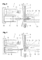
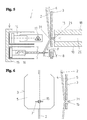
- FIGS. 1 to 8 is a procedure for attaching a thread 2 to a label 3 and in the Figures 9 and 10 a device 1 for performing the method steps is shown. First, the procedure is explained and then the structural design and operation of the device. 1
- FIG. 1 the initial position of a needle 11 is shown, which is associated with the device 1 for fixing a thread 2 to a label 3.
- the thread 2 is made of cotton and the label 3 is made of cardboard or paper, so that the two surfaces 4, 5 of the label 3 can be printed with manufacturer's instructions.
- the thread-label connection is used to hold and label a tea bag, especially if the tea bag is used in a hot water bath, this can be used on the label 3 and the thread 2 manually.
- the needle 11 is in the initial state of FIG. 1 oriented perpendicular to the label 3 and points to the surface 4; It is also conceivable to set the needle 11 at an angle of less than 90 ° to the surface 4.
- an eyelet 12 is incorporated, through which the thread 2 passes.
- a groove 13 is provided in the surface of the needle 11, which is aligned parallel to the longitudinal axis formed by needle 11.
- the needle 11 is reciprocable in the direction of the label 3; This is accomplished essentially by the device 1, as explained in more detail below.
- FIG. 2 It can be seen that the needle 11 has now pierced the label 3 together with the thread 2 and thereby an opening 31, which corresponds to the frayed needle puncture, has arisen in the label 3.
- the abutment 18 consists of a housing 10 in which a bore 26 is incorporated, into which the needle 11 is immersed, so that the movements of the needle 11 are not hindered by the anvil 18.
- a piston 20 is axially displaceably mounted in the bore 26 of the housing 10, which in the position shown the FIG. 2 is positioned in the initial state and thus does not affect the movements of the needle 11.
- FIG. 3 is the needle 11 opposite to the position in FIG. 2 partially withdrawn; However, the label 3 continues to penetrate together with the thread 2. The limited retraction of the needle 11 results in a loop 15 of the thread 2, adjacent to the second surface 5 of the label 3.
- a meltable and adhesive, cylindrical body 21 made of plastic, in particular polyamide or nylon, is provided, which is formed by the loop 15 Level is inserted vertically into the loop 15.
- the body 21 extends in a tube 23, the opening of which is thus aligned parallel to and spaced from the plane formed by the loop 15 and which opens into a hole 10 'incorporated in the housing 10.
- the groove 13 is incorporated and this in the position of FIG. 3 is positioned in alignment with the opening of the tube 23 and thus of the body 21, the body 21 can be inserted into the loop 15 of the thread 2 without being hindered by the needle 11.
- FIG. 4 is shown that the needle 11 is completely pulled out of the label 3, and that the thread 2 is mechanically locked on the second surface 5 of the label 3 by the inserted body 21 on this side of the label 3, so that the thread 2 through the Return movement of the needle 11, at which the thread 2 is still threaded through, is not pulled out of the created by the needle 11 opening 31 in the label 3.
- the thread 2 namely a frictional force is exerted on the body 21, which is formed by the looping and the small opening 31, where the thread 2 is applied.
- the thread 2 is pulled out of the opening 31 by means of a pulling force F in order to press the loop 15 firmly against the body 21.
- the axially movably mounted in the housing 10 piston 20 is now delivered in the direction of the second surface 5 of the label 3 and extends after completion of the feed movement in the plane formed by the housing 10 so that they together form the anvil 18.
- the surface 5 of the facing end surface of the piston 20 is provided with the reference numeral 24, which acts as a cutting edge for the separation of the body 21.
- FIG. 5 It can be seen that the piston 20 bears against the thread 2, the body 21 and thus on the surface 5 of the label 3 and this position of the piston 20 together with the housing 10 forms the counter bearing 18.
- the needle 11 is moved away from the attachment area and a device 1 associated with the heating punch 17 is in the direction of the first Surface 4 of the label 3 delivered and extends in this processing state in alignment with the abutment 18, in particular to the piston 20th
- FIGS. 7 and 8 the gluing or sealing procedure is shown.
- the heating punch 17 rests on the surface 4, so that between the heating punch 17 and the piston 20, first a pressing force on the thread 2, the label. 3 and the body 21 positioned therebetween acts.
- the heating punch 17 and / or the piston 20 is provided with a heat source through which the body 21 is made to melt. By the melting and pressing operation of the body 21, this connects to the thread 2 and the label 3.
- the heating punch 17 and / or the piston 20 of the counter-bearing 18 have, for example, an ultrasound or induction-operated heating device. It is also conceivable to provide the heating punch 17 and / or the piston 20 with heating wires through which the heat generated reaches the body 21 via the heating punch 17 and / or the piston 20.
- the fastening device 7 consists of a frame 19, on which two lifting pistons 16 are arranged.
- the frame 19 is tiltable from the horizontal.
- the needle 11 and the heating punch 17 are alternately positioned to the surface 4 of the label 3 to perform the respective process steps.
- a feeding device 8 of the device 1 through which the label 3 is transported to the fastening device 7.
- the respective preceding label 3, to which the thread 2 has already been attached, is transported further through the thread 2 by means not shown of the packaging machine by the desired distance between the labels.
- the thread length between this and the subsequent label 3 is determined. This ensures the supply of the thread 2.
- the body 21 extends in a tube 23 and is pushed through this by a 10 incorporated in the housing bore 10 '.
- the device 1 has a control, not shown, by which both the feed device 8 and a feed device 22 for the pushing movements of the body 21 are synchronized.
- the movements of the frame 19 and the axial advances of the reciprocating piston 16 are accomplished by the control of the device 1.
- the device 1 is equipped as a modular kit, so that it can be retrofitted to existing teabag packaging machines.
Landscapes
- Engineering & Computer Science (AREA)
- Mechanical Engineering (AREA)
- Labeling Devices (AREA)
Priority Applications (1)
| Application Number | Priority Date | Filing Date | Title |
|---|---|---|---|
| EP10156842A EP2366628A1 (fr) | 2010-03-18 | 2010-03-18 | Procédé et dispositif de fixation d'un fil à une étiquette ainsi que l'étiquette obtenue |
Applications Claiming Priority (1)
| Application Number | Priority Date | Filing Date | Title |
|---|---|---|---|
| EP10156842A EP2366628A1 (fr) | 2010-03-18 | 2010-03-18 | Procédé et dispositif de fixation d'un fil à une étiquette ainsi que l'étiquette obtenue |
Publications (1)
| Publication Number | Publication Date |
|---|---|
| EP2366628A1 true EP2366628A1 (fr) | 2011-09-21 |
Family
ID=42338166
Family Applications (1)
| Application Number | Title | Priority Date | Filing Date |
|---|---|---|---|
| EP10156842A Withdrawn EP2366628A1 (fr) | 2010-03-18 | 2010-03-18 | Procédé et dispositif de fixation d'un fil à une étiquette ainsi que l'étiquette obtenue |
Country Status (1)
| Country | Link |
|---|---|
| EP (1) | EP2366628A1 (fr) |
Cited By (2)
| Publication number | Priority date | Publication date | Assignee | Title |
|---|---|---|---|---|
| WO2016029986A1 (fr) * | 2014-08-28 | 2016-03-03 | Azionaria Costruzioni Macchine Automatiche A.C.M.A. S.P.A. | Appareil pour produire des emballages de produits d'infusion |
| EP4375204A1 (fr) | 2022-11-25 | 2024-05-29 | Häussler & Sauter KG | Procédé et dispositif de fabrication d'un sachet filtre pour boissons chaudes |
Citations (5)
| Publication number | Priority date | Publication date | Assignee | Title |
|---|---|---|---|---|
| DE1229895B (de) * | 1965-02-20 | 1966-12-01 | Hesser Ag Maschf | Vorrichtung zum Befestigen von mit Etiketten versehenen Haltefaeden an Aufgussbeuteln |
| FR2645839A1 (fr) * | 1989-04-13 | 1990-10-19 | Bonomelli Federico | Procede et machine de fabrication continue de sacs en papier-filtre pour infusions et analogues et sacs ainsi obtenus |
| EP0778204A1 (fr) * | 1995-12-07 | 1997-06-11 | TECNOMECCANICA S.r.l. | Machine et procédé pour fabriquer des sachets d'infusion complets |
| US5689936A (en) * | 1991-02-14 | 1997-11-25 | A.G. (Patents) Limited (British Company) | Method and apparatus for manufacturing tagged infusion packages |
| EP0790927B1 (fr) * | 1994-11-15 | 2001-03-14 | Tetley Gb Limited | Procede et appareil permettant de produire des sachets infusion |
-
2010
- 2010-03-18 EP EP10156842A patent/EP2366628A1/fr not_active Withdrawn
Patent Citations (5)
| Publication number | Priority date | Publication date | Assignee | Title |
|---|---|---|---|---|
| DE1229895B (de) * | 1965-02-20 | 1966-12-01 | Hesser Ag Maschf | Vorrichtung zum Befestigen von mit Etiketten versehenen Haltefaeden an Aufgussbeuteln |
| FR2645839A1 (fr) * | 1989-04-13 | 1990-10-19 | Bonomelli Federico | Procede et machine de fabrication continue de sacs en papier-filtre pour infusions et analogues et sacs ainsi obtenus |
| US5689936A (en) * | 1991-02-14 | 1997-11-25 | A.G. (Patents) Limited (British Company) | Method and apparatus for manufacturing tagged infusion packages |
| EP0790927B1 (fr) * | 1994-11-15 | 2001-03-14 | Tetley Gb Limited | Procede et appareil permettant de produire des sachets infusion |
| EP0778204A1 (fr) * | 1995-12-07 | 1997-06-11 | TECNOMECCANICA S.r.l. | Machine et procédé pour fabriquer des sachets d'infusion complets |
Cited By (5)
| Publication number | Priority date | Publication date | Assignee | Title |
|---|---|---|---|---|
| WO2016029986A1 (fr) * | 2014-08-28 | 2016-03-03 | Azionaria Costruzioni Macchine Automatiche A.C.M.A. S.P.A. | Appareil pour produire des emballages de produits d'infusion |
| CN107000862A (zh) * | 2014-08-28 | 2017-08-01 | 建筑自动机械制造A.C.M.A.股份公司 | 用于生产沏泡产品包装的设备 |
| US10457432B2 (en) | 2014-08-28 | 2019-10-29 | Azionaria Costruzioni Macchine Automatiche A.C.M.A. S.P.A. | Apparatus for producing packages of infusion products |
| CN107000862B (zh) * | 2014-08-28 | 2020-01-07 | 建筑自动机械制造A.C.M.A.股份公司 | 用于生产沏泡产品包装的设备 |
| EP4375204A1 (fr) | 2022-11-25 | 2024-05-29 | Häussler & Sauter KG | Procédé et dispositif de fabrication d'un sachet filtre pour boissons chaudes |
Similar Documents
| Publication | Publication Date | Title |
|---|---|---|
| DE69606943T2 (de) | Maschine zur herstellung von aufgussbeuteln, die mittels verbindungsfäden befestigte anhänger aufweisen | |
| DE3410181C2 (de) | Nähmaschine | |
| DE2002776C2 (de) | Vorgefertigter Schleifenzuschnitt für eine Dekorationsschleife sowie Vorrichtung zur Herstellung eines vorgefertigten Schleifenzuschnitts | |
| DE2942997A1 (de) | Loetmetallpackung und herstellungsverfahren fuer diese | |
| DE2944058A1 (de) | Maschine zum einfuehren von bauelementanschlussleitungen in schaltungsplattenloecher | |
| DE69125503T2 (de) | Verfahren und vorrichtung zum ausführen von stickereien mit perlen | |
| DE3923770C2 (de) | Verfahren zur Herstellung von mit einem Faden und einem Anhänger versehenen Aufgußfilterpapierbeuteln und nach diesem Verfahren hergestellter Aufgußfilterpapierbeutel | |
| EP0537106B1 (fr) | Procédé et dispositif pour la reliure des livres, des magazines etc., constitués par des cahiers | |
| EP0432464A1 (fr) | Procédé et dispositif pour la fermeture d'une boucle de cerclage lors du cerclage de produits | |
| EP2650420A1 (fr) | Procédé et dispositif de couture de blocs de livre et voie de fabrication de livres avec un tel dispositif | |
| EP1031526A2 (fr) | Procédé et dispositif pour envelopper des faisceaux de filaments creux | |
| DE1435833B1 (de) | Vorrichtung zur Herstellung und Anbringung von Reissverschluss-Gliederreihen | |
| DE4212167A1 (de) | Verfahren und vorrichtung zum verbinden eines papierbahn-einfaedelteiles mit einer papierbahn | |
| WO2020245119A2 (fr) | Procédé de raccordement de bandes, dispositif de raccordement de bandes, système de traitement et utilisation | |
| DE102011075827A1 (de) | Verfahren zum Zusammennähen von Nähgut | |
| DE1806238C3 (de) | Vorrichtung zum Einnähen eines fortlaufenden Reißverschlußbandes in einen durch einen Schlitz zweigeteilten Träger | |
| DE102009015476B4 (de) | Verfahren und Vorrichtung zur Zuführung gleicher oder verschiedener Folienbänder | |
| DE102013013506B3 (de) | Verfahren zur Herstellung einer Fahrzeugrolloanordnung | |
| DE2342314A1 (de) | Verfahren zur automatischen zufuehrung der metalleinlagen in maschinen zur herstellung von brillenbuegeln | |
| EP2607247B1 (fr) | Procédé et dispositif de fixation mécanique d'un fil sur un corps, notamment une étiquette | |
| DE2023100B2 (de) | Verfahren und Vorrichtung zum Herstellen einer Verbindung zwischen einem ablaufenden Streifen und einem neu bereitgestellten Streifen | |
| DE102018132750A1 (de) | Vorrichtung und verfahren zur anbringung einer klebstoffschicht an einem klebstofflosen einband eines ausweis-, wert- oder sicherheitsdokument | |
| EP4219183B1 (fr) | Appareil et procédé de fabrication d'une carte assemblée à l'aide d'une fenêtre transparente à la lumière | |
| DE2724775A1 (de) | Vorhangband mit oeffnungen sowie verfahren und vorrichtung zu seiner herstellung | |
| EP1990303B1 (fr) | Procédé et dispositif destinés à la liaison de divers matériaux de roving |
Legal Events
| Date | Code | Title | Description |
|---|---|---|---|
| PUAI | Public reference made under article 153(3) epc to a published international application that has entered the european phase |
Free format text: ORIGINAL CODE: 0009012 |
|
| AK | Designated contracting states |
Kind code of ref document: A1 Designated state(s): AT BE BG CH CY CZ DE DK EE ES FI FR GB GR HR HU IE IS IT LI LT LU LV MC MK MT NL NO PL PT RO SE SI SK SM TR |
|
| AX | Request for extension of the european patent |
Extension state: AL BA ME RS |
|
| STAA | Information on the status of an ep patent application or granted ep patent |
Free format text: STATUS: THE APPLICATION IS DEEMED TO BE WITHDRAWN |
|
| 18D | Application deemed to be withdrawn |
Effective date: 20120322 |