EP2366760B1 - Verfahren zum katalytischen Cracken mit feiner Kontrolle des Restgehalts an Koks auf dem Katalysator nach Regenerierung - Google Patents
Verfahren zum katalytischen Cracken mit feiner Kontrolle des Restgehalts an Koks auf dem Katalysator nach Regenerierung Download PDFInfo
- Publication number
- EP2366760B1 EP2366760B1 EP11290065.9A EP11290065A EP2366760B1 EP 2366760 B1 EP2366760 B1 EP 2366760B1 EP 11290065 A EP11290065 A EP 11290065A EP 2366760 B1 EP2366760 B1 EP 2366760B1
- Authority
- EP
- European Patent Office
- Prior art keywords
- catalyst
- regeneration
- stage
- regeneration stage
- regenerated
- Prior art date
- Legal status (The legal status is an assumption and is not a legal conclusion. Google has not performed a legal analysis and makes no representation as to the accuracy of the status listed.)
- Not-in-force
Links
- 239000003054 catalyst Substances 0.000 title claims description 206
- 230000008929 regeneration Effects 0.000 title claims description 159
- 238000011069 regeneration method Methods 0.000 title claims description 159
- 239000000571 coke Substances 0.000 title claims description 96
- 238000000034 method Methods 0.000 title claims description 23
- 238000004523 catalytic cracking Methods 0.000 title claims description 22
- 230000008569 process Effects 0.000 title claims description 22
- 238000002485 combustion reaction Methods 0.000 claims description 87
- 238000006243 chemical reaction Methods 0.000 claims description 55
- 238000002156 mixing Methods 0.000 claims description 25
- 238000005243 fluidization Methods 0.000 claims description 11
- 229930195733 hydrocarbon Natural products 0.000 claims description 9
- 150000002430 hydrocarbons Chemical class 0.000 claims description 9
- 239000004215 Carbon black (E152) Substances 0.000 claims description 6
- 238000012546 transfer Methods 0.000 claims description 5
- 238000009835 boiling Methods 0.000 claims description 3
- 239000000779 smoke Substances 0.000 claims description 3
- 238000011144 upstream manufacturing Methods 0.000 claims 1
- 239000003517 fume Substances 0.000 description 31
- CURLTUGMZLYLDI-UHFFFAOYSA-N Carbon dioxide Chemical compound O=C=O CURLTUGMZLYLDI-UHFFFAOYSA-N 0.000 description 30
- 239000003570 air Substances 0.000 description 29
- QVGXLLKOCUKJST-UHFFFAOYSA-N atomic oxygen Chemical compound [O] QVGXLLKOCUKJST-UHFFFAOYSA-N 0.000 description 21
- 229910052760 oxygen Inorganic materials 0.000 description 21
- 239000001301 oxygen Substances 0.000 description 21
- 238000005336 cracking Methods 0.000 description 18
- 229910002092 carbon dioxide Inorganic materials 0.000 description 14
- 239000007789 gas Substances 0.000 description 14
- 102100023882 Endoribonuclease ZC3H12A Human genes 0.000 description 13
- 101710112715 Endoribonuclease ZC3H12A Proteins 0.000 description 13
- 101100120298 Rattus norvegicus Flot1 gene Proteins 0.000 description 11
- 101100412403 Rattus norvegicus Reg3b gene Proteins 0.000 description 11
- 239000000203 mixture Substances 0.000 description 11
- 230000000694 effects Effects 0.000 description 9
- 101100412394 Drosophila melanogaster Reg-2 gene Proteins 0.000 description 8
- 238000009826 distribution Methods 0.000 description 8
- OKTJSMMVPCPJKN-UHFFFAOYSA-N Carbon Chemical compound [C] OKTJSMMVPCPJKN-UHFFFAOYSA-N 0.000 description 7
- 229910052799 carbon Inorganic materials 0.000 description 7
- 238000005516 engineering process Methods 0.000 description 7
- 238000010438 heat treatment Methods 0.000 description 5
- 238000004519 manufacturing process Methods 0.000 description 5
- IJGRMHOSHXDMSA-UHFFFAOYSA-N Atomic nitrogen Chemical compound N#N IJGRMHOSHXDMSA-UHFFFAOYSA-N 0.000 description 4
- 230000015572 biosynthetic process Effects 0.000 description 4
- 230000003197 catalytic effect Effects 0.000 description 4
- 239000000725 suspension Substances 0.000 description 4
- 239000000567 combustion gas Substances 0.000 description 3
- 230000007423 decrease Effects 0.000 description 3
- JTJMJGYZQZDUJJ-UHFFFAOYSA-N phencyclidine Chemical class C1CCCCN1C1(C=2C=CC=CC=2)CCCCC1 JTJMJGYZQZDUJJ-UHFFFAOYSA-N 0.000 description 3
- 238000004064 recycling Methods 0.000 description 3
- 238000011282 treatment Methods 0.000 description 3
- XLYOFNOQVPJJNP-UHFFFAOYSA-N water Substances O XLYOFNOQVPJJNP-UHFFFAOYSA-N 0.000 description 3
- 229910001868 water Inorganic materials 0.000 description 3
- NINIDFKCEFEMDL-UHFFFAOYSA-N Sulfur Chemical compound [S] NINIDFKCEFEMDL-UHFFFAOYSA-N 0.000 description 2
- 229910021536 Zeolite Inorganic materials 0.000 description 2
- 239000001569 carbon dioxide Substances 0.000 description 2
- HNPSIPDUKPIQMN-UHFFFAOYSA-N dioxosilane;oxo(oxoalumanyloxy)alumane Chemical compound O=[Si]=O.O=[Al]O[Al]=O HNPSIPDUKPIQMN-UHFFFAOYSA-N 0.000 description 2
- 238000010410 dusting Methods 0.000 description 2
- 230000008030 elimination Effects 0.000 description 2
- 238000003379 elimination reaction Methods 0.000 description 2
- 230000005484 gravity Effects 0.000 description 2
- 239000007788 liquid Substances 0.000 description 2
- VUZPPFZMUPKLLV-UHFFFAOYSA-N methane;hydrate Chemical compound C.O VUZPPFZMUPKLLV-UHFFFAOYSA-N 0.000 description 2
- 229910052757 nitrogen Inorganic materials 0.000 description 2
- 230000001737 promoting effect Effects 0.000 description 2
- 238000000926 separation method Methods 0.000 description 2
- 239000002002 slurry Substances 0.000 description 2
- 229910052717 sulfur Inorganic materials 0.000 description 2
- 239000011593 sulfur Substances 0.000 description 2
- 239000010457 zeolite Substances 0.000 description 2
- UGFAIRIUMAVXCW-UHFFFAOYSA-N Carbon monoxide Chemical class [O+]#[C-] UGFAIRIUMAVXCW-UHFFFAOYSA-N 0.000 description 1
- UFHFLCQGNIYNRP-UHFFFAOYSA-N Hydrogen Chemical compound [H][H] UFHFLCQGNIYNRP-UHFFFAOYSA-N 0.000 description 1
- 230000009471 action Effects 0.000 description 1
- 239000012080 ambient air Substances 0.000 description 1
- 230000008901 benefit Effects 0.000 description 1
- 230000033228 biological regulation Effects 0.000 description 1
- 229910002090 carbon oxide Inorganic materials 0.000 description 1
- 230000008859 change Effects 0.000 description 1
- 238000001816 cooling Methods 0.000 description 1
- 230000009849 deactivation Effects 0.000 description 1
- 230000003247 decreasing effect Effects 0.000 description 1
- 230000008021 deposition Effects 0.000 description 1
- 238000013461 design Methods 0.000 description 1
- 238000011161 development Methods 0.000 description 1
- 230000018109 developmental process Effects 0.000 description 1
- 238000004821 distillation Methods 0.000 description 1
- 238000000605 extraction Methods 0.000 description 1
- 239000012530 fluid Substances 0.000 description 1
- 238000004231 fluid catalytic cracking Methods 0.000 description 1
- ZZUFCTLCJUWOSV-UHFFFAOYSA-N furosemide Chemical compound C1=C(Cl)C(S(=O)(=O)N)=CC(C(O)=O)=C1NCC1=CC=CO1 ZZUFCTLCJUWOSV-UHFFFAOYSA-N 0.000 description 1
- 239000001257 hydrogen Substances 0.000 description 1
- 229910052739 hydrogen Inorganic materials 0.000 description 1
- 239000011261 inert gas Substances 0.000 description 1
- 238000005259 measurement Methods 0.000 description 1
- 239000002184 metal Substances 0.000 description 1
- 230000004048 modification Effects 0.000 description 1
- 238000012986 modification Methods 0.000 description 1
- 239000003208 petroleum Substances 0.000 description 1
- 230000009467 reduction Effects 0.000 description 1
- 239000000126 substance Substances 0.000 description 1
- 230000008016 vaporization Effects 0.000 description 1
Images


Classifications
-
- C—CHEMISTRY; METALLURGY
- C10—PETROLEUM, GAS OR COKE INDUSTRIES; TECHNICAL GASES CONTAINING CARBON MONOXIDE; FUELS; LUBRICANTS; PEAT
- C10G—CRACKING HYDROCARBON OILS; PRODUCTION OF LIQUID HYDROCARBON MIXTURES, e.g. BY DESTRUCTIVE HYDROGENATION, OLIGOMERISATION, POLYMERISATION; RECOVERY OF HYDROCARBON OILS FROM OIL-SHALE, OIL-SAND, OR GASES; REFINING MIXTURES MAINLY CONSISTING OF HYDROCARBONS; REFORMING OF NAPHTHA; MINERAL WAXES
- C10G11/00—Catalytic cracking, in the absence of hydrogen, of hydrocarbon oils
- C10G11/14—Catalytic cracking, in the absence of hydrogen, of hydrocarbon oils with preheated moving solid catalysts
- C10G11/18—Catalytic cracking, in the absence of hydrogen, of hydrocarbon oils with preheated moving solid catalysts according to the "fluidised-bed" technique
- C10G11/182—Regeneration
-
- C—CHEMISTRY; METALLURGY
- C10—PETROLEUM, GAS OR COKE INDUSTRIES; TECHNICAL GASES CONTAINING CARBON MONOXIDE; FUELS; LUBRICANTS; PEAT
- C10G—CRACKING HYDROCARBON OILS; PRODUCTION OF LIQUID HYDROCARBON MIXTURES, e.g. BY DESTRUCTIVE HYDROGENATION, OLIGOMERISATION, POLYMERISATION; RECOVERY OF HYDROCARBON OILS FROM OIL-SHALE, OIL-SAND, OR GASES; REFINING MIXTURES MAINLY CONSISTING OF HYDROCARBONS; REFORMING OF NAPHTHA; MINERAL WAXES
- C10G11/00—Catalytic cracking, in the absence of hydrogen, of hydrocarbon oils
- C10G11/14—Catalytic cracking, in the absence of hydrogen, of hydrocarbon oils with preheated moving solid catalysts
- C10G11/18—Catalytic cracking, in the absence of hydrogen, of hydrocarbon oils with preheated moving solid catalysts according to the "fluidised-bed" technique
- C10G11/187—Controlling or regulating
-
- C—CHEMISTRY; METALLURGY
- C10—PETROLEUM, GAS OR COKE INDUSTRIES; TECHNICAL GASES CONTAINING CARBON MONOXIDE; FUELS; LUBRICANTS; PEAT
- C10G—CRACKING HYDROCARBON OILS; PRODUCTION OF LIQUID HYDROCARBON MIXTURES, e.g. BY DESTRUCTIVE HYDROGENATION, OLIGOMERISATION, POLYMERISATION; RECOVERY OF HYDROCARBON OILS FROM OIL-SHALE, OIL-SAND, OR GASES; REFINING MIXTURES MAINLY CONSISTING OF HYDROCARBONS; REFORMING OF NAPHTHA; MINERAL WAXES
- C10G2300/00—Aspects relating to hydrocarbon processing covered by groups C10G1/00 - C10G99/00
- C10G2300/20—Characteristics of the feedstock or the products
- C10G2300/30—Physical properties of feedstocks or products
- C10G2300/301—Boiling range
-
- C—CHEMISTRY; METALLURGY
- C10—PETROLEUM, GAS OR COKE INDUSTRIES; TECHNICAL GASES CONTAINING CARBON MONOXIDE; FUELS; LUBRICANTS; PEAT
- C10G—CRACKING HYDROCARBON OILS; PRODUCTION OF LIQUID HYDROCARBON MIXTURES, e.g. BY DESTRUCTIVE HYDROGENATION, OLIGOMERISATION, POLYMERISATION; RECOVERY OF HYDROCARBON OILS FROM OIL-SHALE, OIL-SAND, OR GASES; REFINING MIXTURES MAINLY CONSISTING OF HYDROCARBONS; REFORMING OF NAPHTHA; MINERAL WAXES
- C10G2300/00—Aspects relating to hydrocarbon processing covered by groups C10G1/00 - C10G99/00
- C10G2300/70—Catalyst aspects
- C10G2300/708—Coking aspect, coke content and composition of deposits
-
- Y—GENERAL TAGGING OF NEW TECHNOLOGICAL DEVELOPMENTS; GENERAL TAGGING OF CROSS-SECTIONAL TECHNOLOGIES SPANNING OVER SEVERAL SECTIONS OF THE IPC; TECHNICAL SUBJECTS COVERED BY FORMER USPC CROSS-REFERENCE ART COLLECTIONS [XRACs] AND DIGESTS
- Y02—TECHNOLOGIES OR APPLICATIONS FOR MITIGATION OR ADAPTATION AGAINST CLIMATE CHANGE
- Y02P—CLIMATE CHANGE MITIGATION TECHNOLOGIES IN THE PRODUCTION OR PROCESSING OF GOODS
- Y02P30/00—Technologies relating to oil refining and petrochemical industry
- Y02P30/40—Ethylene production
Definitions
- the present invention is in the field of catalytic cracking of petroleum fractions, more particularly so-called "heavy" cuts, ie cuts of which less than 10% by weight of the hydrocarbons have a boiling point of less than 350 ° C. .
- the invention relates more particularly to a catalytic cracking process, consisting of at least one reaction zone bringing the catalyst into contact with the hydrocarbons to carry out the catalytic cracking reactions, and a catalyst regeneration zone consisting of minus two interconnected fluidized beds, and allowing fine control of the residual coke content on the catalyst at contents greater than 0.15% by weight, preferably greater than 0.25% by weight.
- the particular arrangement of the regeneration zone which is the subject of the present invention makes it possible to limit the activity of the catalyst in the reaction zone, the process being characterized by the fact that part of the catalyst is exposed to total combustion, the other part being subjected to partial combustion conditions, and the two parts being then mixed to deliver a regenerated catalyst with a perfectly controlled residual coke content of greater than 0.15%.
- the invention is particularly interesting to implement in the case where it is sought to maximize the intermediate cracking cuts such as LCO, or more generally, in the case where it is desired to control the activity.
- catalyst entering the reaction zone maintaining a coke concentration greater than 0.15%, preferably greater than 0.25%, on the regenerated catalyst.
- FCC is a well known process that has undergone many changes since the 1930s (see Avidan A., Shinnar R., "Development of Catalytic Cracking Technology: A Lesson in Chemical Reactor Design", Ind.Eng.Chem.Res, 29, 931-942, 1990 ).
- FCC is a process characterized by a reaction zone in which the cracking reactions are carried out on a zeolitic type catalyst, and a regeneration zone which makes it possible to eliminate by combustion the coke deposited on the catalyst during the reaction reactions. cracking.
- the coked catalyst after cracking in the reaction zone generally contains from 0.5% to 2% coke, generally around 1%.
- the activity of the catalyst depends essentially on the coke content deposited on said catalyst, and therefore on the quality of the regeneration. If the catalyst is well regenerated, with a residual coke content (CRC) lower than 0.15%, it is considered that the activity of said catalyst is restored.
- CRC residual coke content
- the control of combustion on a simple regenerator is mainly related to the ratio between the amount of oxygen available for combustion and the amount of coke to burn. Thus, if the mass ratio between air and coke flows in the regenerator is close to 9 -10, then the CO / CO2 ratio in the fumes is close to 1.
- the mass ratio between the flow rates of air and coke at the inlet of the regeneration is closer to 13-15, then it is possible to achieve a total combustion of the coke, the CO / CO2 ratio in the fumes then being less than 0.1 or even 0.01.
- Partial combustion is less exothermic and leads to a more limited catalyst heating. On the other hand, it does not make it possible to completely regenerate the catalyst, and in general, the higher the CO / CO2 ratio of the fumes, the more the coke content on the regenerated catalyst increases. It is common to obtain coke contents on the regenerated catalyst regeneration output, between 0.3 and 0.7% by weight, or 15% to 50% of the coke entering the regenerator.
- the conversion decreases as the residual coke content on the regenerated catalyst increases.
- LCO abbreviation of Light Cycle Oil
- LCO maximization is therefore achieved by cracking at moderate conversion levels, which can be achieved either by lowering the cracking temperature, or by limiting the catalyst circulation, or by limiting the activity of the catalyst by, for example, partial regeneration.
- Controlling an FCC equipped with a simple regenerator and operating in partial combustion is not easy. It is indeed difficult to control both the residual coke content and the CO / CO2 ratio of the fumes. Indeed, the kinetics of combustion governing the conversion of carbon to CO or to CO2 depend on Naturally, the temperature, the partial pressure in water, but these reactions are more or less accelerated depending on the metal content of the catalyst or its composition.
- the combustion is therefore more or less partial or total and the CO / CO2 ratio of the fumes, the temperature or the residual coke content can vary significantly.
- the residual coke content is not measured in-line on the unit and can significantly modify the catalytic activity in the riser.
- the patent US4,666,586 describes a multi-stage regeneration having a first upflow regeneration zone, a second regeneration zone with a fluidized chamber having a dense bed and a third regeneration zone with a fluidized chamber having a dense bed.
- the double regeneration uses a first stage of regeneration, operated in a fluidized bed, in which the coked catalyst coming from the reaction zone is brought into contact with air.
- Reg1 is referred to as the first stage of the regeneration or first regenerator
- Reg 2 the second stage of the regeneration or second regenerator.
- Reg1 In the first regeneration stage, noted Reg1, is usually burned between 50% and 80% of the coke deposited on the catalyst, by contacting with only a portion of the air required to regenerate the entire catalyst.
- the fumes rich in CO are removed from Reg1. Residual CO is burned outside the unit.
- the heating of the catalyst in the first regenerator is limited by the partial combustion, part of the heat of combustion being produced outside the regenerator by the ultimate combustion of CO in a separate boiler for example to produce steam.
- the partially regenerated catalyst is transported to the second fluidized bed regeneration stage Reg 2.
- Reg 2 When Reg 2 is located above the first regenerator, which is the most common case, the transport of the catalyst from Reg 1 to Reg 2 can be performed by a pneumatic air transport line, the transport air participating in the regeneration process.
- the amount of air introduced is in excess of to the needs of combustion, which is easily ascertainable by measuring continuous excess oxygen in the fumes (generally between 0.5 and 4% by volume of dry fumes, preferably between 1 and 3% by volume).
- the exothermicity of the total combustion is important and causes, despite the combustion of smaller quantities of coke than at the first regenerator, a heating of the catalyst still very significant.
- the coke content here is about 1.4%.
- the coke content of the catalyst is about 0.4% -0.5%, and at the outlet of the second regenerator, the coke content of the catalyst is about 0.05%.
- the configuration of the regeneration zone directs the thermal balance of the FCC and makes it possible to process variable Carbon Conradson charges.
- Table 1 summarizes the charges that can be treated by an FCC according to the type of regeneration, the charge being described here by the Conradson Carbon, which sums up its ability to coker well.
- Table 1 Simple regeneration in total combustion : ⁇ 2.5% Conradson Carbon Simple regeneration in partial combustion : ⁇ 3.5% Conradson Carbon Double regeneration (R2R process) : ⁇ 6-7% Carbon Conradson
- the present invention makes it possible to treat all the feeds according to Table 1 with a very fine control of the residual coke content at the regeneration outlet, which makes it possible to orient at will the structure of the yields, in particular towards the LCO when the the coke content of the catalyst at the inlet of the reaction zone is in the range of 0.25% to 0.7%, as a function of the feedstocks and the catalysts, and preferably in the range 0.3% -0, 4%.
- the present invention relates to an implementation of the regeneration of the catalyst in a catalytic cracking process, in which a very fine control of the residual coke level is sought, ie after regeneration.
- the invention describes a two-stage regeneration zone a first stage working in partial combustion, and a second stage working in total combustion, the catalyst circuit between the two stages comprising a completely regenerated catalyst return line. from the second stage, to the first stage, or to a dedicated fluidized chamber in which said catalyst is mixed with the partially regenerated catalyst from the first stage.
- the present invention makes it possible to obtain a fine adjustment of the residual coke level on the regenerated catalyst by controlling the flow of catalyst from the second regeneration stage.
- the catalyst resulting from the mixing and having the required level of residual coke is returned to the reaction zone in which the cracking reactions of the heavy load take place.
- the catalyst resulting from the regeneration is partially regenerated with a mean residual coke content greater than 0.15%, preferably greater than 0.25%, a portion of the regenerated catalyst having been exposed to total combustion conditions and having a residual coke content of less than 0.1%.
- the invention according to the following claims can be defined as a process for the catalytic cracking of a hydrocarbon feedstock with a boiling point greater than 350 ° C., allowing a fine control of the residual coke level on the regenerated catalyst, said process comprising at least one reaction zone bringing into contact with the hydrocarbon feedstock to be treated and the catalyst, and a regeneration zone of said coked catalyst leaving the reaction zone, said regeneration zone being divided into a first regeneration stage in fluidized bed working in partial combustion (ie in air failure), and generating a catalyst whose residual coke content is between 0.3% and 0.7%, and a second regeneration stage in bed fluidized placed in series with respect to the first stage, and working in total combustion (ie in excess of air) and generating a catalyst whose residual coke rate is less than 0.15%, the regenerated catalyst obtained as a result of the partially regenerated and fully regenerated catalyst mixture having a residual coke level greater than 0.15%, preferably greater than 0.25%, and being returned to the reaction zone.
- controlling the coke content of the regenerated catalyst to adjust the catalytic activity is not simple to achieve using available regeneration technologies, including the single-stage regeneration technology.
- the object of the present invention is therefore to overcome this difficulty by providing a catalyst regeneration system for fine control of the coke content on the residual catalyst through an original arrangement of the regeneration zone.
- the proposed system is characterized in that the regeneration zone is composed of at least two stages in a fluidized bed, the catalyst coming from the reaction zone being introduced into the first stage operating in partial combustion, then into the second stage operating in total combustion and placed in series with respect to the first stage, the regenerated catalyst from the second stage returning to the reaction zone after mixing with the catalyst from the first stage, and the circulation of the catalyst between the first stage operating in partial combustion and the second stage operating in total combustion being controlled.
- the regenerated catalyst according to the invention that is to say resulting from the mixing between, on the one hand, partially regenerated catalyst with a residual coke content of between 0.3 and 0, 7% and, secondly, fully regenerated catalyst with a residual coke content of less than 0.15%, is not equivalent to partially regenerated catalyst that would have an intermediate residual coke rate in proportion to the mass flows.
- the implementation of the invention will preferably be carried out in regeneration stages operating in a turbulent regime or in a transport regime, corresponding for conventional FCC catalysts, at surface speeds of fluidization gas in the regenerator greater than 0.3. m / s for the turbulent regime, and greater than 1.6 m / s for the transport regime.
- the figure 1 below describes a first embodiment of the invention.
- the coked catalyst from the reactor is introduced via a conduit (1) into an enclosure containing a first fluidized bed (2) corresponding to the first regeneration stage.
- the catalyst is brought into contact with a gas (3) containing oxygen, for example previously compressed air, air enriched with oxygen or oxygen, more or less diluted, for example by combustion fumes.
- the combustion gas is introduced into the lower part of the fluidized bed by means (4) allowing a good distribution of the gas on the section of the regenerator.
- These means are for example dispensing rings, branched multi-pipes or perforated hole plates, means well known to those skilled in the art which allow a uniform fluidization of the catalyst on the section of the regenerator (2).
- the fluidization rate in the dense phase of the fluidized bed will be maintained between 0.3 and 1.6 m / s, preferably between 0.5 and 1.2 m / s.
- the combustion takes place essentially in the dense phase.
- the fumes will nonetheless cause in the dilute phase of the regenerator significant quantities of catalyst and the dedusting of the fumes is carried out in a first step inside the regenerator by a single stage cyclone (5) or double stage.
- the combustion in the regenerator (2) is partial.
- the CO / CO2 ratio of the fumes is high and can typically be between 0.3 and 2.
- Fumes containing significant amounts of CO are removed from the regenerator downstream of the cyclones (6) and then undergo post-treatments such as CO afterburning, final dusting, turbining and heat exchange to recover a portion of the energy of the fumes, the elimination of the oxides of sulfur and nitrogen, even the separation of the CO2.
- the catalyst is withdrawn from the first regeneration stage (2) by a pipe (7) taking the catalyst in the dense phase of the fluidized bed to transport it to the reaction zone in which the cracking reactions of the hydrocarbons contained in the feed are carried out. heavy.
- Part of the catalyst flowing in the first regeneration stage (2) is also withdrawn and directed to the second regeneration stage (8) located above the first regeneration stage (2).
- the transfer of catalyst between the two stages is carried out by means of a transport line (9) fed by a gas flow (10), whose composition may be similar to the composition of the gas (3).
- the catalyst flow rate in the transport line (9) is controlled by the positioning of a plug valve (11) at the base of the transport tube (9).
- the gas used as carrier in the transport line (9) contains oxygen, a significant part of the combustion can occur during transport.
- the gas flow rate (10) for transport in the lift will be kept constant and will achieve speeds preferably between 5 m / s and 10 m / s.
- the transported catalyst stream will advantageously be between 100 and 800 kg / s / m2, preferably between 300 and 600 kg / s / m2, which makes it possible to minimize the transport gas and the pressure dissipation associated with the transport.
- the suspension constituted by the partially regenerated catalyst from the first regeneration chamber and the transport gas is introduced through openings located in the upper part of the transport line (9) in the second regeneration stage ( 8).
- the catalyst is brought into contact with an oxygen-containing combustion gas (13), for example pre-compressed ambient air, oxygen-enriched air or oxygen, more or less diluted, for example by combustion fumes.
- an oxygen-containing combustion gas for example pre-compressed ambient air, oxygen-enriched air or oxygen, more or less diluted, for example by combustion fumes.
- the combustion gas (13) is introduced into the lower part of the fluidized bed with means (12) allowing a good distribution of the gas over the entire section of the reactor (8).
- introduction means (12) are, for example, distribution rings, branched multi-pipes, or perforated hole plates, which are well known to those skilled in the art, which allow a uniform fluidization of the catalyst over the entire section of the regenerator. .
- the fluidization rate in the dense phase of the fluidized bed will preferably be maintained between 0.3 and 1.3 m / s, preferably between 0.5 and 1 m / s.
- the fumes will nevertheless cause in the dilute phase of the regenerator (8) significant quantities of catalyst, and the dedusting of the fumes is carried out in a first step by a single-stage cyclone (14) as shown in FIG. figure 1 or double-stage, inside or outside the regenerator.
- the combustion in the regenerator (8) is complete.
- the CO / CO2 ratio of the fumes (15) is very low and is generally less than 0.05 or even 0.01.
- the simple measurement of the oxygen content in the dry fumes, easily achievable makes it possible to check that excess oxygen remains after the combustion.
- An oxygen content of the fumes of the order of 1-2% vol generally makes it possible to ensure that the combustion is complete.
- the fumes (6) containing significant amounts of CO are removed from the first regeneration stage downstream of the cyclones (5), and then undergo post-treatments such as ultimate dusting, turbining and heat exchange to recover a temperature. part of the energy of the fumes, the elimination of the oxides of sulfur and nitrogen, even the separation of CO2.
- the fumes (15) of the second regeneration stage (8) can be cleverly combined with the fumes (6) of the first regeneration stage to perform the post-treatments.
- the regenerated catalyst in the second regeneration stage (8) is then returned to the first regeneration stage (2). So in the case described on the figure 1 specific means for withdrawing the catalyst from the enclosure (8) to the enclosure (2) are implemented.
- a lateral transfer line (17) supplying a fluidized enclosure (16) operating at a fluidization velocity of between 0.05 m / s and 0.1 m / s.
- the catalyst descending into this chamber at a speed of less than 0.5 m / s, fluidized enclosure (16) in which the bubbles transported with the catalyst are disengaged, then the suspension is accelerated in a lower conical portion (19) prior to bringing the downflowing catalyst slurry into a substantially vertical transport tube (20) in which the slurry travels with a speed ideally between 1 m / s and 3 m / s.
- a valve (21) is positioned at the bottom of the transport tube (20) and allows for example to maintain a constant level of catalyst in the second regeneration stage (8).
- the transport tube (20) discharges the suspension through its opening (22) in the dense phase or in the dilute phase of the first regeneration chamber (2).
- the tube (20) discharges the suspension into the dense phase of the first regeneration stage (2).
- “Close” is understood to mean that the point of introduction of the coked catalyst from the reaction zone and the point of introduction of the regenerated catalyst from the second regeneration stage (8) are spaced a distance apart. not exceeding the radius of the first regeneration stage (2).
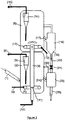
- the figure 2 represents another embodiment of the invention.
- the catalyst from the second regeneration stage (8) is not reintroduced into the first regeneration stage (2) but is mixed with the catalyst stream withdrawn from the first regeneration stage (2) in a chamber (23). ) operating in a fluidized bed from which the mixture obtained is redirected to the reaction zone via the line (25).
- the bed of the mixing chamber (23) is fluidized with an inert gas (N 2, H 2 O) or with an oxygen-containing gas to perform part of the combustion.
- the fumes resulting from said combustion are, for example, remixed in the dilute phase of the first regeneration stage by means of a duct (30) connecting the mixing chamber (23) and the diluted phase of the first regeneration stage (2).
- the enclosure (23) is a mixing zone. It is characterized by a mean residence time of the catalyst preferably less than 60s.
- the fluidization rate remains moderate and preferably less than 10 cm / s. In the case where a heat exchanger is installed to extract some of the heat released by the combustion of the coke in the regenerator, it may be advantageous to install the heat exchanger in this chamber (23).
- the essential difference between the configuration described on the figure 1 and the configuration described on the figure 2 resides in the fact that the temperature at which the partial combustion takes place in the first regeneration stage is higher in the case where the catalyst is reintroduced into said first regeneration stage (according to FIG. figure 1 ), which promotes combustion reactions by making them faster.
- the temperature may be advisable to limit the temperature to the first regeneration stage (2), for example to reduce the hydrothermal deactivation of the zeolite, and the configuration described on the figure 2 is then particularly suitable for units operating with high coke deposits on the catalyst.
- the temperature of the first regeneration stage (2) it is generally desired to limit the temperature of the first regeneration stage (2) to values of less than 730.degree. C., preferably of less than 710.degree.
- the figure 3 is a variant of two-stage regeneration zone.
- the first regeneration stage (27) is located above the second regeneration stage (26).
- the catalyst from the reaction zone (28) arrives in the first reaction zone (27) above the second reaction zone (26). It is withdrawn from the first reaction zone via line (29) to be reintroduced partially regenerated in the reaction zone. Circulation between the two regeneration chambers is possible by gravity flow from the first regeneration stage (27) to the second regeneration stage (26) through the withdrawal well (16) having a lower conical portion (19). ), the transport tube (20) and the valve (21).
- Pneumatic transport from the second stage (26) to the first stage (28) is carried out through the plug valve (11) and the lift (9).
- the advantage of the invention lies in a regeneration system which allows a fine control of the residual coke content deposited on the regenerated catalyst, ie returning to the reaction zone, in a FCC operating in partial combustion.
- the configurations of the regeneration zone described in the figures 1 and 2 are particularly suited to adjusting the control of the activity of the catalyst via the deposition of coke on the catalyst.
- the means of action is the catalyst flow that has undergone total regeneration in the second regeneration stage (8), to the first regeneration stage (2), or to the fluidized mixing chamber (23).
- the amount of catalyst exposed to total regeneration conditions depends directly on the circulation of circulating catalyst from the first regeneration stage (2) to the second stage (8).
- This amount of catalyst is easily controllable through the transport systems provided with valves (21) located between the two regenerators. It is for example possible to impose a flow setpoint by controlling the opening of the valve positioned on the transport line between the regenerator operating in partial combustion and the regenerator operating in total combustion, and to enslave the opening of the valve (21) located on the transport line of the regenerator operating total combustion (8) to the regenerator operating in partial combustion (2) to the regulation of a constant level to the regenerator operating in total combustion. This strategy then makes it possible to continuously and finely control the amount of catalyst undergoing total combustion.
- the variation of the catalyst circulation is accompanied by a modification of the distribution of the air flow between the two regeneration stages, in order to maintain regeneration conditions adapted to the total combustion in the second regenerator, characterized by an excess of oxygen in the fumes of at least 0.5% volume relative to the dry fumes, preferably greater than 1% volume relative to the dry fumes.
- This exchanger will preferentially cool catalyst from the second regenerator, already exposed to total regeneration conditions. With such equipment installed in the regeneration zone, if the amount of heat extracted is adjusted according to the catalyst circulation, then it is possible to vary the coke content of the regenerated catalyst without changing its flow rate to the cracking reaction zone. catalytic operated with a flow rate and a constant temperature.
- MTC technology abbreviation of "mix temperature control” that can be translated by control of the mixing temperature
- the first example describes the operation of a catalytic cracking unit operating with a regeneration system identical to that described in FIG. figure 1 .
- the catalyst is regenerated in a two regenerator system with only a portion of the catalyst being exposed to total combustion conditions.
- the second example describes the operation of the same catalytic cracking unit operating with a regeneration system identical to that described in FIG. Figure 2 , in which a heat exchanger of variable power has been installed in the chamber (23) for mixing partially regenerated and fully regenerated catalysts.
Landscapes
- Chemical & Material Sciences (AREA)
- Oil, Petroleum & Natural Gas (AREA)
- Engineering & Computer Science (AREA)
- Chemical Kinetics & Catalysis (AREA)
- General Chemical & Material Sciences (AREA)
- Organic Chemistry (AREA)
- Production Of Liquid Hydrocarbon Mixture For Refining Petroleum (AREA)
Claims (8)
- Verfahren zum katalytischen Kracken einer Kohlenwasserstoffcharge mit einem Siedepunkt von mehr als 350°C, unter Verwendung einer feinen Steuerung derMenge an Koksrückstand auf dem regenerierten Katalysator, wobei das Verfahrenmindestens eine Reaktionszone, die im Wanderbett die zu behandelnde Kohlenwasserstoffcharge und den Katalysator in Kontakt bringt, und eine Regenerationszone des gekokten Katalysators am Ausgang der Reaktionszone umfasst, wobei die Regenerationszone geteilt ist in eine erste Regenerationsstufe (2) im Fließbett, die mit partieller Verbrennung arbeitet, das heißt ohne Luftzufuhr, wobei ein Katalysator erzeugt wird, dessen Gehalt an Koksrückstandzwischen 0,3 % und 0,7 % liegt, und in eine zweite Regenerationsstufe (8) im Fließbett, die in Bezug auf die erste Stufe in Serie angeordnet ist und mit vollständiger Verbrennung arbeitet, das heißt mit Luftüberschuss, und wobei ein Katalysator erzeugt wird, dessen Gehalt an Koksrückstand geringer ist als 0,15 %, wobei der Transfer des Katalysators von der ersten zur zweiten Stufe durch die Transportleitung (9) vorgenommen wird, die von einem Gasdurchsatz (10) gespeist wird und mit einem Steuerventil (11) des Katalysatordurchsatzes versehen ist, das an der Basis des Transportrohrs (9) angeordnet ist, wobei der regenerierte Katalysator, der nach der Mischung des partiell regenerierten und vollständig regenerierten Katalysators erhalten wird, einen Gehalt an Koksrückstand von mehr als 0,15 % und bevorzugt mehr als 0,25 % aufweist, wobei der Koksgehalt durch die Steuerung der Zirkulation des am Ausgang der zweiten Regenerationsstufe erhaltenen, vollständig regenerierten Katalysators erhalten wird, dera) entweder in die erste Regenerationsstufe mit Hilfe einer Transferleitung (17), eines Fließbehälters (16), eines Transportrohrs (20) und eines Steuerventils (21) zurückgeschickt wird, die erste Stufe, aus welcher der Katalysator, der aus der Mischung der beiden Stufen erhalten wird und die gewünschte Menge an Koks besitzt, zur Reaktionszone durch die Leitung (7) zurückgeschickt wird,b) oder in einen dedizierten Mischbehälter (23) mit Hilfe einer Transferleitung (17), eines Fließbehälters (16), eines Transportrohrs (20) und eines Steuerventils (21) geschickt wird, in dem sich der vollständig regenerierte Katalysator mit dem partiell regenerierten Katalysator aus der ersten Regenerationsstufe mischt, aus dem der Katalysator, der durch die Mischung erhalten wird und die gewünschte Menge an Koks besitzt, in die Reaktionszone durch die Leitung (25) zurückgeschickt wird,
wobei das Verfahrendadurch gekennzeichnet ist, dass der Katalysator aus der zweiten Regenerationsstufe, die mit vollständiger Verbrennung arbeitet, in die erste Regenerationsstufe, die mit partieller Verbrennung arbeitet, oder in den Mischbehälter (23) mit Hilfe einer Einheit von Leitungen zurückgeschickt wird, die in Fließrichtung des Katalysators umfassen:1) den Fließbehälter (16), der mit einer Fließgeschwindigkeit zwischen 0,05 m/s und 0,1 m/s arbeitet, wobei der Katalysator in diesem Behälter absteigende Katalysator eine Geschwindigkeit von weniger als 0,5 m/s aufweist,2) das Transportrohr (20 mit einer Transportgeschwindigkeit des Katalysators zwischen 1 und 3 m/s arbeitet,3) das Steuerventil (21) des Katalysatordurchsatzes, das auf der Höhe des Katalysators in der zweiten Regenerationsstufe gesteuert wird und das im Fall b) stromaufwärts vom Mischbehälter (23) angeordnet ist. - Verfahrenzum katalytischen Kracken, welches die feine Steuerung der Menge an Koksrückstand auf dem regenerierten Katalysator nach Anspruch 1 gestattet, wobei der Katalysator aus der zweiten Regenerationsstufe, die mit vollständiger Verbrennung arbeitet, in einen Mischfließbehälter (23) zurückgeschickt wird, der mit einer Fließgeschwindigkeit von weniger als 10 cm/s betrieben wird, in dem er sich mit dem Katalysator aus der ersten Stufe (2) mischt, aus dem der aus der Mischung erhaltene Katalysator zur Reaktionszone zurückgeschickt wird.
- Verfahren zum katalytischen Kracken, welches die feine Steuerung der Menge an Koksrückstand auf dem regenerierten Katalysator nach Anspruch 1 gestattet, wobei die erste Regenerationsstufe mit einer Fließgeschwindigkeit zwischen 0,3 und 1,6 m/s und bevorzugtzwischen 0,5 und 1,2 m/s betrieben wird.
- Verfahren zum katalytischen Kracken, welches die feine Steuerung der Menge an Koksrückstand auf dem regenerierten Katalysator nach Anspruch 1 gestattet, wobei die erste Regenerationsstufe mit einem Verhältnis CO/CO2 in den Abgasen zwischen 0,3 und 2 betrieben wird.
- Verfahren zum katalytischen Kracken, welches die feine Steuerung der Menge an Koksrückstand auf dem regenerierten Katalysator nach Anspruch 1 gestattet, wobei die zweite Regenerationsstufe mit einer Fließgeschwindigkeit zwischen 0,3 und 1,3 m/s und bevorzugtzwischen 0,5 und 1 m/s betrieben wird.
- Verfahren zum katalytischen Kracken, welches die feine Steuerung der Menge an Koksrückstand auf dem regenerierten Katalysator nach Anspruch 1 gestattet, wobei die zweite Regenerationsstufe mit einem Verhältnis CO/CO2 in den Abgasen von weniger als 0,05 und bevorzugt von weniger als 0,01 betrieben wird.
- Verfahren zum katalytischen Kracken, welches die feine Steuerung der Menge an Koksrückstand auf dem regenerierten Katalysator nach Anspruch 1 gestattet, wobei der Wiedereinführungspunkt des regenerierten Katalysators aus der zweiten Regenerationsstufe in die erste Stufe von dem Ankunftspunkt des gekokten Katalysators aus der Reaktionszone in einer Distanz beabstandet ist, die kleiner ist als der Radius der ersten Regenerationsstufe.
- Verfahren zum katalytischen Kracken, welches die feine Steuerung der Menge an Koksrückstand auf dem regenerierten Katalysator nach Anspruch 1 gestattet, wobei ein Wärmetauscher, der Dampf erzeugt, in den dedizierten Behälter platziert ist, wo sich der regenerierte Katalysator aus der zweiten Regenerationsstufe mit dem partiell regenerierten Katalysator aus der ersten Regenerationsstufe mischt.
Applications Claiming Priority (1)
| Application Number | Priority Date | Filing Date | Title |
|---|---|---|---|
| FR1001031A FR2957352B1 (fr) | 2010-03-15 | 2010-03-15 | Procede de craquage catalytique avec controle fin de la teneur en coke residuelle sur le catalyseur apres regeneration |
Publications (2)
| Publication Number | Publication Date |
|---|---|
| EP2366760A1 EP2366760A1 (de) | 2011-09-21 |
| EP2366760B1 true EP2366760B1 (de) | 2017-09-06 |
Family
ID=42338179
Family Applications (1)
| Application Number | Title | Priority Date | Filing Date |
|---|---|---|---|
| EP11290065.9A Not-in-force EP2366760B1 (de) | 2010-03-15 | 2011-01-31 | Verfahren zum katalytischen Cracken mit feiner Kontrolle des Restgehalts an Koks auf dem Katalysator nach Regenerierung |
Country Status (3)
| Country | Link |
|---|---|
| US (1) | US8551326B2 (de) |
| EP (1) | EP2366760B1 (de) |
| FR (1) | FR2957352B1 (de) |
Families Citing this family (7)
| Publication number | Priority date | Publication date | Assignee | Title |
|---|---|---|---|---|
| WO2011097811A1 (zh) * | 2010-02-11 | 2011-08-18 | Li Li | 一种冷再生催化剂循环方法及其设备 |
| CN103717289A (zh) | 2011-04-11 | 2014-04-09 | Ada-Es股份有限公司 | 用于气体组分捕集的流化床方法和系统 |
| US20130130889A1 (en) * | 2011-11-17 | 2013-05-23 | Stone & Webster Process Technology, Inc. | Process for maximum distillate production from fluid catalytic cracking units (fccu) |
| US9278314B2 (en) | 2012-04-11 | 2016-03-08 | ADA-ES, Inc. | Method and system to reclaim functional sites on a sorbent contaminated by heat stable salts |
| US9283533B1 (en) * | 2014-08-26 | 2016-03-15 | Uop Llc | Catalyst regenerators and methods for regenerating catalysts |
| CN116212971B (zh) * | 2021-12-03 | 2024-10-11 | 中国石油化工股份有限公司 | 一种催化剂再生设备以及再生方法 |
| CN116920962B (zh) * | 2022-04-02 | 2025-09-26 | 中国海洋石油集团有限公司 | 含两种催化剂的混合物的联合再生及在线分离方法和原料油直接制化学品的方法 |
Family Cites Families (9)
| Publication number | Priority date | Publication date | Assignee | Title |
|---|---|---|---|---|
| US4417975A (en) * | 1980-11-30 | 1983-11-29 | Ashland Oil, Inc. | Addition of water to regeneration air |
| US4601814A (en) * | 1983-05-27 | 1986-07-22 | Total Engineering And Research Company | Method and apparatus for cracking residual oils |
| US4780195A (en) * | 1983-07-25 | 1988-10-25 | Ashland Oil, Inc. | Addition of water to regeneration air |
| US4666586A (en) * | 1983-10-11 | 1987-05-19 | Farnsworth Carl D | Method and arrangement of apparatus for cracking high boiling hydrocarbon and regeneration of solids used |
| US4556479A (en) | 1984-04-10 | 1985-12-03 | Total Engineering And Research Company | Method for the clean-up of particulate-catalyst containing gases |
| US4849091A (en) * | 1986-09-17 | 1989-07-18 | Uop | Partial CO combustion with staged regeneration of catalyst |
| US5077251A (en) * | 1990-07-17 | 1991-12-31 | Mobil Oil Corporation | Control of multistage catalyst regeneration with both partial and full co combustion |
| US5346613A (en) * | 1993-09-24 | 1994-09-13 | Uop | FCC process with total catalyst blending |
| US6869521B2 (en) * | 2002-04-18 | 2005-03-22 | Uop Llc | Process and apparatus for upgrading FCC product with additional reactor with thorough mixing |
-
2010
- 2010-03-15 FR FR1001031A patent/FR2957352B1/fr active Active
-
2011
- 2011-01-31 EP EP11290065.9A patent/EP2366760B1/de not_active Not-in-force
- 2011-03-15 US US13/048,184 patent/US8551326B2/en not_active Expired - Fee Related
Non-Patent Citations (1)
| Title |
|---|
| None * |
Also Published As
| Publication number | Publication date |
|---|---|
| EP2366760A1 (de) | 2011-09-21 |
| US20110220548A1 (en) | 2011-09-15 |
| FR2957352A1 (fr) | 2011-09-16 |
| US8551326B2 (en) | 2013-10-08 |
| FR2957352B1 (fr) | 2012-05-18 |
Similar Documents
| Publication | Publication Date | Title |
|---|---|---|
| EP1800742B1 (de) | Reaktor mit zwei fluidisierbaren Reaktionsstufen und einem integrierten Gas/Feststofftrennsystem | |
| EP2366760A1 (de) | Verfahren zum katalytischen Cracken mit feiner Kontrolle des Restgehalts an Koks auf dem Katalysator nach Regenerierung | |
| EP1413622B1 (de) | Verfahren zur flüssigen katalytischen Spaltung in zwei integrierten, mit unterschiedlicher Strenge, bei einer Abkühlungszone gefolgten Spaltenzonen | |
| CA2052520C (fr) | Procede et dispositif de craquage catalytique en lit fluide a courant descendant | |
| CA2850612C (fr) | Procede de combustion en boucle chimique avec elimination des cendres et fines en sortie de la zone d'oxydation et installation utilisant un tel procede | |
| EP2786069B1 (de) | Chemisches kreislaufverbrennungsverfahren mit verdünnungsphasenentfernung von asche und feinstoffen in der oxidierungszone sowie anlage zur durchführung eines solchen verfahrens | |
| EP2981350B1 (de) | Verfahren und vorrichtung zur verbrennung von flüssigen kohlenwasserstoffbeschickungen in einem chemischen kreislauf | |
| FR2624762A1 (fr) | Procede et dispositif de regeneration de catalyseur en lit fluidise | |
| EP2658950B1 (de) | Katalytisches krackverfahren zur behandlung einer fraktion mit niedrigem gehalt an conradson-kohlenstoff | |
| CA1259577A (fr) | Procede et appareil pour craquage catalytique en lit fluide | |
| FR2966836A1 (fr) | Procede de reformage de coupes hydrocarbonees. | |
| EP0184517B1 (de) | Verfahren und Anlagen für das katalytische Kracken von Kohlenwasserstoffeinsätzen | |
| EP2627736B1 (de) | Mehrstufiges rissbildungs- und ablösungsverfahren in einer fcc-einheit | |
| WO2009138595A2 (fr) | Masse active d'oxydo-reduction et procédé de combustion en boucle chimique | |
| EP2726576B1 (de) | Katalytisches krackverfahren zur behandlung einer fraktion mit niedrigem gehalt an conradson-kohlenstoff | |
| EP0699224B1 (de) | Verfahren zur regelung des erhitzungsgrades eines feststoffes in einem waermetauscher mit ringfoermig angeordneten rohrbuendeln | |
| FR2753454A1 (fr) | Procede et dispositif de craquage catalytique descendant mettant en oeuvre l'injection d'une charge sous un angle adequat sur un catalyseur conditionne | |
| EP0291408B1 (de) | Dampfspaltungsverfahren in einer Wirbelschicht-Reaktionszone | |
| EP0536054B1 (de) | Verbesserungen an Vorrichtungen für das katalytische Wirbelschichtkracken von Kohlenwasserstoffeinsätzen | |
| FR2770225A1 (fr) | Procede et dispositif de vaporisation selective des charges d'hydrocarbures en craquage catalytique | |
| EP1016444B1 (de) | Verfahren und Vorrichtung für die schnelle Abtrennung von festen Partikeln aus gasförmigen Fluiden und ihre Anwendung | |
| FR2633848A1 (fr) | Procede et dispositif de regeneration d'un catalyseur use avec echange thermique en lit fluidise | |
| EP0322276A1 (de) | Verfahren und Einrichtung für das katalytische Kracken von schweren Einsätze, die eine zweite Wirbelschichtabstreifzone enthalten | |
| BE525055A (de) | ||
| BE532311A (de) |
Legal Events
| Date | Code | Title | Description |
|---|---|---|---|
| PUAI | Public reference made under article 153(3) epc to a published international application that has entered the european phase |
Free format text: ORIGINAL CODE: 0009012 |
|
| AK | Designated contracting states |
Kind code of ref document: A1 Designated state(s): AL AT BE BG CH CY CZ DE DK EE ES FI FR GB GR HR HU IE IS IT LI LT LU LV MC MK MT NL NO PL PT RO RS SE SI SK SM TR |
|
| AX | Request for extension of the european patent |
Extension state: BA ME |
|
| 17P | Request for examination filed |
Effective date: 20120321 |
|
| 17Q | First examination report despatched |
Effective date: 20160210 |
|
| GRAP | Despatch of communication of intention to grant a patent |
Free format text: ORIGINAL CODE: EPIDOSNIGR1 |
|
| INTG | Intention to grant announced |
Effective date: 20170512 |
|
| GRAS | Grant fee paid |
Free format text: ORIGINAL CODE: EPIDOSNIGR3 |
|
| GRAA | (expected) grant |
Free format text: ORIGINAL CODE: 0009210 |
|
| AK | Designated contracting states |
Kind code of ref document: B1 Designated state(s): AL AT BE BG CH CY CZ DE DK EE ES FI FR GB GR HR HU IE IS IT LI LT LU LV MC MK MT NL NO PL PT RO RS SE SI SK SM TR |
|
| REG | Reference to a national code |
Ref country code: GB Ref legal event code: FG4D Free format text: NOT ENGLISH |
|
| REG | Reference to a national code |
Ref country code: CH Ref legal event code: EP Ref country code: AT Ref legal event code: REF Ref document number: 925917 Country of ref document: AT Kind code of ref document: T Effective date: 20170915 |
|
| REG | Reference to a national code |
Ref country code: IE Ref legal event code: FG4D Free format text: LANGUAGE OF EP DOCUMENT: FRENCH |
|
| REG | Reference to a national code |
Ref country code: DE Ref legal event code: R096 Ref document number: 602011041264 Country of ref document: DE |
|
| RAP2 | Party data changed (patent owner data changed or rights of a patent transferred) |
Owner name: IFP ENERGIES NOUVELLES |
|
| REG | Reference to a national code |
Ref country code: NL Ref legal event code: MP Effective date: 20170906 |
|
| REG | Reference to a national code |
Ref country code: LT Ref legal event code: MG4D |
|
| PG25 | Lapsed in a contracting state [announced via postgrant information from national office to epo] |
Ref country code: LT Free format text: LAPSE BECAUSE OF FAILURE TO SUBMIT A TRANSLATION OF THE DESCRIPTION OR TO PAY THE FEE WITHIN THE PRESCRIBED TIME-LIMIT Effective date: 20170906 Ref country code: SE Free format text: LAPSE BECAUSE OF FAILURE TO SUBMIT A TRANSLATION OF THE DESCRIPTION OR TO PAY THE FEE WITHIN THE PRESCRIBED TIME-LIMIT Effective date: 20170906 Ref country code: NO Free format text: LAPSE BECAUSE OF FAILURE TO SUBMIT A TRANSLATION OF THE DESCRIPTION OR TO PAY THE FEE WITHIN THE PRESCRIBED TIME-LIMIT Effective date: 20171206 Ref country code: HR Free format text: LAPSE BECAUSE OF FAILURE TO SUBMIT A TRANSLATION OF THE DESCRIPTION OR TO PAY THE FEE WITHIN THE PRESCRIBED TIME-LIMIT Effective date: 20170906 Ref country code: FI Free format text: LAPSE BECAUSE OF FAILURE TO SUBMIT A TRANSLATION OF THE DESCRIPTION OR TO PAY THE FEE WITHIN THE PRESCRIBED TIME-LIMIT Effective date: 20170906 |
|
| REG | Reference to a national code |
Ref country code: AT Ref legal event code: MK05 Ref document number: 925917 Country of ref document: AT Kind code of ref document: T Effective date: 20170906 |
|
| PG25 | Lapsed in a contracting state [announced via postgrant information from national office to epo] |
Ref country code: ES Free format text: LAPSE BECAUSE OF FAILURE TO SUBMIT A TRANSLATION OF THE DESCRIPTION OR TO PAY THE FEE WITHIN THE PRESCRIBED TIME-LIMIT Effective date: 20170906 Ref country code: GR Free format text: LAPSE BECAUSE OF FAILURE TO SUBMIT A TRANSLATION OF THE DESCRIPTION OR TO PAY THE FEE WITHIN THE PRESCRIBED TIME-LIMIT Effective date: 20171207 Ref country code: RS Free format text: LAPSE BECAUSE OF FAILURE TO SUBMIT A TRANSLATION OF THE DESCRIPTION OR TO PAY THE FEE WITHIN THE PRESCRIBED TIME-LIMIT Effective date: 20170906 Ref country code: LV Free format text: LAPSE BECAUSE OF FAILURE TO SUBMIT A TRANSLATION OF THE DESCRIPTION OR TO PAY THE FEE WITHIN THE PRESCRIBED TIME-LIMIT Effective date: 20170906 Ref country code: BG Free format text: LAPSE BECAUSE OF FAILURE TO SUBMIT A TRANSLATION OF THE DESCRIPTION OR TO PAY THE FEE WITHIN THE PRESCRIBED TIME-LIMIT Effective date: 20171206 |
|
| PG25 | Lapsed in a contracting state [announced via postgrant information from national office to epo] |
Ref country code: NL Free format text: LAPSE BECAUSE OF FAILURE TO SUBMIT A TRANSLATION OF THE DESCRIPTION OR TO PAY THE FEE WITHIN THE PRESCRIBED TIME-LIMIT Effective date: 20170906 |
|
| PG25 | Lapsed in a contracting state [announced via postgrant information from national office to epo] |
Ref country code: PL Free format text: LAPSE BECAUSE OF FAILURE TO SUBMIT A TRANSLATION OF THE DESCRIPTION OR TO PAY THE FEE WITHIN THE PRESCRIBED TIME-LIMIT Effective date: 20170906 Ref country code: RO Free format text: LAPSE BECAUSE OF FAILURE TO SUBMIT A TRANSLATION OF THE DESCRIPTION OR TO PAY THE FEE WITHIN THE PRESCRIBED TIME-LIMIT Effective date: 20170906 Ref country code: CZ Free format text: LAPSE BECAUSE OF FAILURE TO SUBMIT A TRANSLATION OF THE DESCRIPTION OR TO PAY THE FEE WITHIN THE PRESCRIBED TIME-LIMIT Effective date: 20170906 |
|
| PG25 | Lapsed in a contracting state [announced via postgrant information from national office to epo] |
Ref country code: IT Free format text: LAPSE BECAUSE OF FAILURE TO SUBMIT A TRANSLATION OF THE DESCRIPTION OR TO PAY THE FEE WITHIN THE PRESCRIBED TIME-LIMIT Effective date: 20170906 Ref country code: EE Free format text: LAPSE BECAUSE OF FAILURE TO SUBMIT A TRANSLATION OF THE DESCRIPTION OR TO PAY THE FEE WITHIN THE PRESCRIBED TIME-LIMIT Effective date: 20170906 Ref country code: SK Free format text: LAPSE BECAUSE OF FAILURE TO SUBMIT A TRANSLATION OF THE DESCRIPTION OR TO PAY THE FEE WITHIN THE PRESCRIBED TIME-LIMIT Effective date: 20170906 Ref country code: IS Free format text: LAPSE BECAUSE OF FAILURE TO SUBMIT A TRANSLATION OF THE DESCRIPTION OR TO PAY THE FEE WITHIN THE PRESCRIBED TIME-LIMIT Effective date: 20180106 Ref country code: SM Free format text: LAPSE BECAUSE OF FAILURE TO SUBMIT A TRANSLATION OF THE DESCRIPTION OR TO PAY THE FEE WITHIN THE PRESCRIBED TIME-LIMIT Effective date: 20170906 Ref country code: AT Free format text: LAPSE BECAUSE OF FAILURE TO SUBMIT A TRANSLATION OF THE DESCRIPTION OR TO PAY THE FEE WITHIN THE PRESCRIBED TIME-LIMIT Effective date: 20170906 |
|
| REG | Reference to a national code |
Ref country code: DE Ref legal event code: R097 Ref document number: 602011041264 Country of ref document: DE |
|
| PLBE | No opposition filed within time limit |
Free format text: ORIGINAL CODE: 0009261 |
|
| STAA | Information on the status of an ep patent application or granted ep patent |
Free format text: STATUS: NO OPPOSITION FILED WITHIN TIME LIMIT |
|
| PG25 | Lapsed in a contracting state [announced via postgrant information from national office to epo] |
Ref country code: DK Free format text: LAPSE BECAUSE OF FAILURE TO SUBMIT A TRANSLATION OF THE DESCRIPTION OR TO PAY THE FEE WITHIN THE PRESCRIBED TIME-LIMIT Effective date: 20170906 |
|
| REG | Reference to a national code |
Ref country code: DE Ref legal event code: R119 Ref document number: 602011041264 Country of ref document: DE |
|
| 26N | No opposition filed |
Effective date: 20180607 |
|
| PG25 | Lapsed in a contracting state [announced via postgrant information from national office to epo] |
Ref country code: SI Free format text: LAPSE BECAUSE OF FAILURE TO SUBMIT A TRANSLATION OF THE DESCRIPTION OR TO PAY THE FEE WITHIN THE PRESCRIBED TIME-LIMIT Effective date: 20170906 |
|
| REG | Reference to a national code |
Ref country code: CH Ref legal event code: PL |
|
| GBPC | Gb: european patent ceased through non-payment of renewal fee |
Effective date: 20180131 |
|
| PG25 | Lapsed in a contracting state [announced via postgrant information from national office to epo] |
Ref country code: MT Free format text: LAPSE BECAUSE OF FAILURE TO SUBMIT A TRANSLATION OF THE DESCRIPTION OR TO PAY THE FEE WITHIN THE PRESCRIBED TIME-LIMIT Effective date: 20170906 |
|
| PG25 | Lapsed in a contracting state [announced via postgrant information from national office to epo] |
Ref country code: LU Free format text: LAPSE BECAUSE OF NON-PAYMENT OF DUE FEES Effective date: 20180131 Ref country code: FR Free format text: LAPSE BECAUSE OF NON-PAYMENT OF DUE FEES Effective date: 20180131 Ref country code: DE Free format text: LAPSE BECAUSE OF NON-PAYMENT OF DUE FEES Effective date: 20180801 |
|
| REG | Reference to a national code |
Ref country code: IE Ref legal event code: MM4A |
|
| REG | Reference to a national code |
Ref country code: FR Ref legal event code: ST Effective date: 20180928 |
|
| REG | Reference to a national code |
Ref country code: BE Ref legal event code: MM Effective date: 20180131 |
|
| PG25 | Lapsed in a contracting state [announced via postgrant information from national office to epo] |
Ref country code: LI Free format text: LAPSE BECAUSE OF NON-PAYMENT OF DUE FEES Effective date: 20180131 Ref country code: CH Free format text: LAPSE BECAUSE OF NON-PAYMENT OF DUE FEES Effective date: 20180131 Ref country code: GB Free format text: LAPSE BECAUSE OF NON-PAYMENT OF DUE FEES Effective date: 20180131 Ref country code: BE Free format text: LAPSE BECAUSE OF NON-PAYMENT OF DUE FEES Effective date: 20180131 |
|
| PG25 | Lapsed in a contracting state [announced via postgrant information from national office to epo] |
Ref country code: IE Free format text: LAPSE BECAUSE OF NON-PAYMENT OF DUE FEES Effective date: 20180131 |
|
| PG25 | Lapsed in a contracting state [announced via postgrant information from national office to epo] |
Ref country code: MC Free format text: LAPSE BECAUSE OF FAILURE TO SUBMIT A TRANSLATION OF THE DESCRIPTION OR TO PAY THE FEE WITHIN THE PRESCRIBED TIME-LIMIT Effective date: 20170906 |
|
| PG25 | Lapsed in a contracting state [announced via postgrant information from national office to epo] |
Ref country code: TR Free format text: LAPSE BECAUSE OF FAILURE TO SUBMIT A TRANSLATION OF THE DESCRIPTION OR TO PAY THE FEE WITHIN THE PRESCRIBED TIME-LIMIT Effective date: 20170906 |
|
| PG25 | Lapsed in a contracting state [announced via postgrant information from national office to epo] |
Ref country code: HU Free format text: LAPSE BECAUSE OF FAILURE TO SUBMIT A TRANSLATION OF THE DESCRIPTION OR TO PAY THE FEE WITHIN THE PRESCRIBED TIME-LIMIT; INVALID AB INITIO Effective date: 20110131 Ref country code: PT Free format text: LAPSE BECAUSE OF FAILURE TO SUBMIT A TRANSLATION OF THE DESCRIPTION OR TO PAY THE FEE WITHIN THE PRESCRIBED TIME-LIMIT Effective date: 20170906 |
|
| PG25 | Lapsed in a contracting state [announced via postgrant information from national office to epo] |
Ref country code: CY Free format text: LAPSE BECAUSE OF FAILURE TO SUBMIT A TRANSLATION OF THE DESCRIPTION OR TO PAY THE FEE WITHIN THE PRESCRIBED TIME-LIMIT Effective date: 20170906 Ref country code: MK Free format text: LAPSE BECAUSE OF NON-PAYMENT OF DUE FEES Effective date: 20170906 |
|
| PG25 | Lapsed in a contracting state [announced via postgrant information from national office to epo] |
Ref country code: AL Free format text: LAPSE BECAUSE OF FAILURE TO SUBMIT A TRANSLATION OF THE DESCRIPTION OR TO PAY THE FEE WITHIN THE PRESCRIBED TIME-LIMIT Effective date: 20170906 |