EP2366833B1 - Vorrichtung zum Auftragen von Strassenmarkierung - Google Patents
Vorrichtung zum Auftragen von Strassenmarkierung Download PDFInfo
- Publication number
- EP2366833B1 EP2366833B1 EP10157045.5A EP10157045A EP2366833B1 EP 2366833 B1 EP2366833 B1 EP 2366833B1 EP 10157045 A EP10157045 A EP 10157045A EP 2366833 B1 EP2366833 B1 EP 2366833B1
- Authority
- EP
- European Patent Office
- Prior art keywords
- applicator device
- tape
- tape applicator
- lifting arrangement
- roller
- Prior art date
- Legal status (The legal status is an assumption and is not a legal conclusion. Google has not performed a legal analysis and makes no representation as to the accuracy of the status listed.)
- Not-in-force
Links
- 229920002379 silicone rubber Polymers 0.000 claims description 5
- 239000004945 silicone rubber Substances 0.000 claims description 5
- 239000000463 material Substances 0.000 claims description 4
- 230000002093 peripheral effect Effects 0.000 claims description 3
- 239000007788 liquid Substances 0.000 claims description 2
- 238000000034 method Methods 0.000 description 9
- 239000000853 adhesive Substances 0.000 description 3
- 230000005540 biological transmission Effects 0.000 description 3
- 238000003825 pressing Methods 0.000 description 3
- 230000001070 adhesive effect Effects 0.000 description 2
- 238000002485 combustion reaction Methods 0.000 description 2
- 238000005520 cutting process Methods 0.000 description 2
- 230000005484 gravity Effects 0.000 description 2
- 239000002184 metal Substances 0.000 description 2
- 238000005096 rolling process Methods 0.000 description 2
- 241001244599 Requena Species 0.000 description 1
- 239000002390 adhesive tape Substances 0.000 description 1
- 230000000694 effects Effects 0.000 description 1
- 238000003860 storage Methods 0.000 description 1
Images



Classifications
-
- E—FIXED CONSTRUCTIONS
- E01—CONSTRUCTION OF ROADS, RAILWAYS, OR BRIDGES
- E01C—CONSTRUCTION OF, OR SURFACES FOR, ROADS, SPORTS GROUNDS, OR THE LIKE; MACHINES OR AUXILIARY TOOLS FOR CONSTRUCTION OR REPAIR
- E01C23/00—Auxiliary devices or arrangements for constructing, repairing, reconditioning, or taking-up road or like surfaces
- E01C23/16—Devices for marking-out, applying, or forming traffic or like markings on finished paving; Protecting fresh markings
- E01C23/18—Devices for marking-out, applying, or forming traffic or like markings on finished paving; Protecting fresh markings for applying prefabricated markings
- E01C23/185—Tape- or sheet-shape markers or carriers
Definitions
- the invention relates to a tape applicator for applying a road marking tape on pavement, and in particular to a tape applicator having a lifting arrangement. Furthermore, the invention relates a method of using a tape applicator device and a method of lifting a tape applicator device.
- Pavement marking is often made by application of a pre-fabricated adhesive coated marking tape to the pavement of a road, for example.
- a marking tape is typically applied by use of mechanical devices which position the tape on the pavement. Some of those devices are designed for not only positioning the tape but also for pressing the tape with the adhesive side down on the pavement to establish a sufficient adhesion of the tape on the pavement.
- self-propelled devices For marking of relatively long distances self-propelled devices are often used. Such devices are typically motorized and relatively robust in design so that they can carry relatively heavy rolls holding a maximized length of tape, and to provide the required directional stability for accurately positioning the tape.
- US 6,413,013 B1 discloses an autonomous strip laying device for marking ground.
- the device includes a rolling frame which supports a reel of strip to be unwound, a strip unwinding assembly, elements for applying the strip on the ground including an applicator roll, a device for sectioning the strip and an assembly driving the frame and actuating the different devices and the unwinding elements.
- US 4,030,958 discloses a pavement-striping apparatus for automatically feeding tape from a roll and pressing it into contact with a paved surface in continuous stripes or intermittent stripes of variable spacing, width, and length.
- the apparatus has an engagement roller for bringing the tape in engagement with the paved surface, and a pressure roller to more firmly adhere the tape to the roadway.
- the apparatus further has a front wheel which can be engaged against the surface for storage or other kinds of handling of the stripping apparatus.
- motorized devices for applying self-adhesive tapes overcome some difficulties associated with propelling the device over long distances and up hills, there is still a desire to provide a device which is easy to handle, but which further is relatively inexpensive.
- the invention relates to a pavement marking tape applicator device.
- the device is adapted for applying pavement marking tape on a surface along a longitudinal dimension.
- the device comprises:
- longitudinal dimension of the tape applicator device for the purpose of this specification generally refers to a dimension that is oriented generally parallel to the direction in which the device is moved for applying tape on a road surface.
- the invention is advantageous in that it preferably provides a tape applicator device which is movable at a maximized directional stability, but which can be turned or otherwise moved away from the location of tape application in an easy way.
- the invention further preferably provides for a device which can easily be moved and relocated when the tape application operation is interrupted. Therefore, the invention makes a steering roller having a large steering angle, which may reduce the directional stability, unnecessary. Also, the invention makes a separate additional device such as a crane, which would lift the device for turning or relocation on the surface, unnecessary.
- the invention may be advantageous in that it may provide a device that can be used with various methods of applying marking tape on a road. Further a device of the invention may be relatively inexpensive and robust.
- the invention may be advantageous in that it provides for a smaller turning circle compared to the turning radius of a tape applicator device having a steerable roller with a limited steering angle. Further a device of the invention may be advantageous as the turning operation may only require a short interruption of tape application.
- the lifting arrangement comprises a support member.
- the support member is preferably movable for positioning the lifting arrangement between a first position, in which the lifting arrangement is spaced from the surface, and a second position, in which the lifting arrangement engages the surface such that the rollers are disengaged from the surface.
- the tape applicator device In the first position of the lifting arrangement the tape applicator device may be supported on the surface by the first and second rollers only. In the second position of the lifting arrangement, the tape applicator device is supported by the support member only.
- the lifting of the tape applicator device generally allows for turning the tape applicator device about a turning axis.
- the lifting arrangement in the second position may enable a rotation of the tape applicator device about the turning axis.
- the turning axis is preferably oriented generally perpendicular to the surface, and further preferably, the turning axis is additionally oriented generally perpendicular to the longitudinal dimension of the tape applicator device. Further the turning axis is preferably positioned within a perpendicular projection of the outer shape of the tape applicator device onto the surface.
- the tape applicator device may for example be turned by applying a manual force to the device in a direction into which the device should be turned.
- Certain components of the tape applicator device may be arranged or fixed at the chassis.
- at least one of the first and second rollers, the lifting arrangement, a tape supply roll, a tape guiding and advancing mechanism, and a motor for advancing the device may be arranged or fixed at the chassis.
- the support member has a first end which is fixed at the tape applicator device and a free second end which is movable for positioning the lifting arrangement in the first and/or the second position(s).
- the lifting arrangement further comprises a support plate.
- the support plate is preferably arranged at the second end of the support member. Further the support plate may have a contact surface for contacting the surface onto which tape is to be applied.
- the contact surface may be generally planar and may have a generally rectangular, generally circular or any other suitable shape. Preferably, the contact surface is generally circular, and may have in a preferred embodiment a diameter of about 180 mm.
- the support plate may be made of metal, for example, or of any other material having appropriate mechanical stability.
- the lifting arrangement comprises a swivel-joint providing for rotatability of the support plate (150) and the support member (110) relative to one another about the turning axis.
- the support plate thus may be arranged rotatably at the lifting arrangement about the turning axis. Therefore the tape applicator device in the second position of the lifting arrangement may be enabled to be turned about the turning axis while the support plate is substantially positionally fixed relative to the surface.
- the contact surface comprises silicone rubber.
- the contact surface of the support plate thus may prevent or at least minimize the support plate from slipping or sliding on the surface.
- the lifting arrangement comprises a support wheel.
- the support wheel is preferably arranged at the second end of the support member.
- the support wheel is preferably adapted for rolling on the surface. Therefore the support wheel preferably has a rotation axis that is oriented generally parallel to the surface. Further the support wheel is preferably further arranged rotatably at the lifting arrangement about the turning axis. Therefore the support wheel and the support member may be rotatable relative to each other in two different dimensions.
- the tape applicator device may be enabled to be turned about the turning axis with the support wheel further allowing the device to be moved laterally to the turning axis.
- the support wheel may be made out of metal or any other sufficiently stable material.
- the support wheel has a diameter of at least 150 mm.
- the support wheel comprises an outer peripheral contact surface for contacting the surface.
- the contact surface preferably comprises silicone rubber. Thereby, a more reliable contact between support wheel and the surface may be provided. The contact surface of the support wheel thus may prevent or at least minimize the support wheel from slipping or sliding on the surface.
- the lifting arrangement comprises a swivel-joint providing for rotatability of the support wheel (140) and the support member (110) relative to one another about the turning axis.
- the support member comprises a lever extending between the first end and the second end. Therefore the support member is preferably pivotally suspended at the tape applicator device. Preferably the support member is pivotable about a pivot axis that is oriented substantially parallel to the surface. The first end of the lever may be pivotally fixed at the tape applicator device so that the second end by rotation of the lever can be moved toward or away from the surface. Thus the support member is enabled for positioning the lifting arrangement between the first and second positions.
- the lifting arrangement may have a support member which is variable in length, for example may comprise telescopically cooperating members.
- the first end of the support member may be fixed at the device and the second end may be movable linearly towards or away from the surface. Thereby, the support member may position the lifting arrangement between the first and second positions.
- the lifting arrangement further comprises an actuation member.
- the actuation member is provided for moving the support member to position the lifting arrangement between the first and the second position.
- the actuation member is preferably adapted to bias the support member towards the surface. Biasing the support member towards the surface may allow for lifting of the tape applicator device so that the rollers are disengaged from the surface. Further this may enable the device to be turned, for example manually turned.
- the actuation member may be powered or driven by the drive unit of the tape application device or a separate source of energy.
- the actuation member has a first and a second end, wherein the first end is coupled with the support member and the second end is coupled to a further part of the tape applicator device.
- the actuation member may be operable by at least one of spring load, gas pressure, liquid pressure, magnetic force and hand operation of an operator.
- the actuation member is a pneumatic cylinder.
- the tape applicator device may further have a control element which may be operable by a user for user-selective loading and unloading the actuation member from the spring. Thus the device may be lifted by spring load and lowered by releasing the spring load.
- the support member is preferably arranged between the first and second rollers.
- the support member is particularly arranged with its second end between the rollers at least in the second position of the lifting arrangement. Because the first roller and the second roller are typically arranged at the device such that the center of gravity is between the applicator and the support rollers, the lifting arrangement may thus enable for lifting at least part of the device including the first and second rollers.
- the entire lifting arrangement may be arranged between the rollers. This may allow for a relatively compact, simple and robust design of the device.
- the support member is arranged at the device such that in the second position of the lifting arrangement the device is supported in the center of gravity of the tape applicator device. Thereby, the device may be supported by the support member at minimized risk of tilting.
- the tape applicator device comprises an applicator roller for positioning tape on the surface and a support roller for supporting the device on the surface.
- the first roller may comprise or form the applicator roller
- the second roller may comprise or form the support roller.
- the applicator and support rollers preferably have a width (which is the dimension of the roller along its cylinder or rotation axis) allowing for application of differently wide tapes, or for application of two or more tapes side by side.
- the applicator and support rollers have an outer peripheral surface provided by a silicone rubber material.
- the rollers may deform when pressed on the tape or surface for providing a certain surface pressure rather than a narrow line contact pressure.
- the applicator roller is preferably of the same diameter and width as the support roller. The applicator roller and the support roller may together carry the entire weight on the device, in the second position of the lifting arrangement.
- the support roller is rotatable about a steering axis which is oriented generally perpendicular to a rotation axis of the support roller and to the longitudinal dimension.
- the device may be easily maneuverable straight and along curves, and may allow for applying tape in a straight or curved manner.
- the tape applicator device is motorized for automatic advancing the tape applicator at least during tape application. This preferably facilitates an operation of the device over long distances.
- the tape applicator device may for example have a combustion engine, or an electric engine. Further the tape applicator device may comprise at least one of an electric generator, a pneumatic compressor, and a hydraulic pump. Therefore the tape applicator device may operate entirely independent over a relative long time period. This may make the device advantageous particularly for long distance road marking.
- the lifting arrangement may be adapted to move one or both of the rollers relative to the surface.
- the lifting arrangement may have at least one or two support members which carry/carries the first and/or the second rollers.
- the support member(s) thus may instead of the support plate or support wheel carry the first and/or second roller(s), but may otherwise correspond to embodiments as defined above.
- the first and/or second rollers are preferably movable away from and/or toward the surface.
- the background of the invention relates to a method of lifting a tape applicator device.
- the method comprises the steps of:
- the method comprises the step of lifting the tape applicator device by positioning the lifting arrangement in the second position such that the first and the second rollers are disengaged from the surface.
- the method comprises the step of turning the tape applicator device in the second position of the lifting arrangement about a turning axis that is oriented generally perpendicular to the surface.
- the method comprises the step of lowering the tape applicator device by positioning the lifting arrangement to the first position such that the first and the second rollers are engaged with the surface.
- Fig. 1 a shows a tape applicator device 10 according to an embodiment of the invention.
- the tape applicator device 10 is adapted to place a pre-manufactured, preferably self-adhesive, marking tape on a surface, for example a paved road surface.
- the tape applicator device has a tape feeding unit 12, a drive unit 13, and an application unit 18.
- the tape feeding unit 12 basically provides for conveying tape from a supply toward the application unit 18 where it can be applied to the surface.
- the feeding unit 12 further comprises a cutter 14 and a splicing table 15.
- the tape feeding unit 13 allows for cutting individual stripes of a certain length from a longer tape, for example, for applying intermittent segments of marking tape.
- the feeding unit 13 via the splicing table 15 allows for splicing of the ends of two tapes, for example when the tape applicator device 10 has to be provided with a new supply of tape during application of a continuous marking.
- the drive unit 13 preferably enables the tape applicator device 10 to be automatically advanced, for example for applying tape, in a direction (indicated by the arrow in the Figure) parallel to a longitudinal dimension of the device. Further the drive unit 13 may provide for driving further items in the tape applicator device 10, for example the cutter and/or other items of the feeding unit 12.
- the drive unit 13 may comprise a combustion engine or electric motor. The drive unit 13 may also power or drive the actuation member 120 of the lifting arrangement 100.
- the device shown has a chassis 19 which carries the feeding unit 12 and the drive unit 13, and at which the application unit is arranged.
- the chassis 19 further provides a roll mounting for receiving a tape supply roll 17.
- a tape supply roll holds a maximized length of tape, for example several hundred meters, to enable long time periods of continuous tape application. Therefore the tape supply roll 17 may weigh approximately 30 kg or more.
- the tape applicator device 10 is sufficiently stable to carry at least one of such a tape supply roll.
- the tape applicator device 10 preferably is adapted to receive two or more tape supply rolls side by side. Thus once a roll is empty further tape may be supplied from another roll present in the device without the need to exchange the empty roll. Therefore the operation of the device may only be discontinued over a short time period required to feed the new tape toward the application unit 18. Further a side by side arrangement of the supply rolls preferable allows for application of two or more markings side by side on the surface.
- the position(s) of the tape supply roll(s) are preferably laterally adjustable so that, for example, two or more side by side markings spaced by a defined distance from each other may be created on the surface.
- the tape applicator device has an applicator roller 20 and a support roller 30 which together support the tape applicator device 10 on the surface 40.
- the applicator roller 20 and the support roller 30 are preferably fixed at the device in a height dimension (which is a dimension generally perpendicular to the surface 40 to which tape may be applied).
- the applicator roller 20 and the support roller 30 preferably have a fixed position in a height dimension relative to each other. This preferably prevents skewing of the rollers 20, 30 relative to one another which may result in directional variations when the tape applicator device is moved.
- the applicator roller 20 and the support roller 30 in cooperation may thus provide for a relatively precise directional stability during advancement of the tape applicator device.
- At least one of the support roller 30 and the applicator roller 20 may be steerable about a steering axis that is oriented generally parallel to the height dimension of the device 10. This preferably allows rotating of one or both of the applicator and the support rollers 20, 30 about the steering axis for moving the device along a curve. Therefore the device 10 can preferably also be maneuvered during operation, for example for creating curved markings.
- the support roller 30 is steerable.
- the support roller 30 is steerable by a steering wheel 11.
- the steering wheel 11 preferably cooperates with the support roller 30 via a transmission to rotate the support roller 30 at a fixed transmission ratio about the steering axis.
- the transmission preferably provides for a reduction between a rotation of the steering wheel 11 and the support roller 30.
- a rotation of the steering wheel 11 by a first angle may provide for the support roller 30 to rotate about the steering axis by a second angle which is smaller than the first angle.
- the direction in which the tape applicator device 10 can be advanced may be controlled relatively precisely. Therefore the device 10 may allow the application of relatively precise curved markings.
- the tape applicator device 10 further has a lifting arrangement 100.
- the lifting arrangement 100 in the example shown comprises a lever 110, which is arranged at the chassis 19.
- the lever 110 is pivotable at the device about a pivot axis 160, which is oriented generally perpendicular to the surface 40.
- the lever 110 is adapted to contact the surface 40 for supporting the device 10 on the surface 40.
- the lever 110 is in a first position. In the first position the lever 110 is spaced from the surface 40.
- the tape applicator device 10 further has an actuation member 120 for moving the lever to position the lifting arrangement between the first position and a second position (illustrated in Fig. 1b ).
- Fig. 1b shows the tape applicator device 10 with the lifting arrangement 100 in the second position.
- the lever 110 contacts the surface 40, and the tape applicator device is lifted from the surface 40 such that the applicator roller 20 as well as the support roller 30 are spaced from the surface 40.
- the tape applicator device 10 is supported only by the lever 110 of the lifting arrangement 100.
- the lever 110 carries a support plate 150.
- the lever 110 and the support plate 150 are rotatable relative to each other about a turning axis 190 which is oriented generally perpendicular to the surface 40.
- the lifting arrangement 100 enables the tape applicator to be turned on the support plate 150 about the turning axis in the second position lifting arrangement 100.
- the tape applicator device 10 may for example be turned manually by an operator.
- Fig. 2 illustrates details of the lifting arrangement 100 of the tape applicator 10.
- the lever 110 has a first end at which the lever 110 is pivotally fixed at the device and a free second end carrying the support plate 150.
- the support plate 150 and the second end of the lever are connected via a swivel-joint 130 which enables for the rotation between the lever 110 and the support plate.
- the lever 110 of the lifting arrangement 100 is movable by the actuation member 120.
- the actuation member 120 is coupled with a first end to the lever 110 and with an opposite second end to the chassis of the tape applicator device 10.
- the actuation member 120 may comprise for example a pneumatic cylinder.
- the pneumatic cylinder thus preferably allows for moving the lever of the lifting arrangement such that it pivots about axis 160.
- actuating members providing a similar or an equivalent effect, like for example a hydraulic cylinder, a magnetic actuator, or a combination of two or more actuation members including springs and other resilient elements.
- the lifting arrangement 100 is in the second position, in which the rollers 20, 30 are lifted relative to the surface.
- Fig. 3 is a further side view illustrating the details of the lifting arrangement 100 described under Figure 2 .
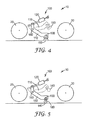
- Fig. 4 schematically shows certain details of the tape applicator 10 placed on a surface 40.
- the lifting arrangement 100 with the lever 110 and the actuation member 120 is arranged between the applicator roller 20 and the support roller 30.
- the lever 110 is illustrated in the second position of the lifting arrangement by solid lines. Further the lever 110 in the first position of the lifting arrangement is indicated by dashed lines.
- Fig. 5 shows an example of a tape applicator device 10 having an alternative lifting arrangement 100.
- the lever 110 of the lifting arrangement 100 comprises a support wheel 140.
- the support wheel 140 has a rotation axis 180, which is oriented parallel to the surface 40.
- the support wheel 140 is attached to the lever by the swivel-joint 130 which further enables the support wheel to rotate about the turning axis (not shown in this Figure).
- Fig. 6 schematically shows a further embodiment of the lifting arrangement 100 of the tape applicator device 10.
- a leg 110 is arranged for telescopically cooperating with a collet 115.
- the leg 110 thus is linearly movable towards or away from the surface 40.
- the leg 110 of the lifting arrangement 100 is shown in solid lines in the first position, in which it is disengaged from the surface 40.
- the second position of the lifting arrangement 100 in which the tape applicator device is lifted is indicated by dotted lines.
- the tape applicator device 10 further has an actuation member 120, for example a pneumatic cylinder, by which the leg 110 may be moved to position the lifting arrangement 100 between the first and second positions.
- the actuation member 120 is coupled at a first end to the leg 110 and with an opposite second end to the device 10.
- Fig. 7 is a schematic top view on the tape applicator and illustrates turning of the tape applicator device 10.
- the support plate 150 is arranged underneath the device and therefore, because it is not visible in the top view, only indicated by dotted lines.
- the tape applicator device 10 is lifted and may therefore be turned.
- An operator may apply a force to the tape applicator device 10, to turn the device into a desired direction (indicated by arrow A). This may facilitate the handling of the tape applicator device 10 particularly for maneuvering the device around sharp curves or to position the device for tape application into opposite directions.
- the position of the tape applicator device 10 in an initial situation is shown by solid lines, whereas the position of the turned device 10 is indicated by dashed lines.
Landscapes
- Engineering & Computer Science (AREA)
- Architecture (AREA)
- Civil Engineering (AREA)
- Structural Engineering (AREA)
- Road Repair (AREA)
- Adhesive Tape Dispensing Devices (AREA)
- Coating Apparatus (AREA)
Claims (13)
- Fahrbahnmarkierungsband-Applikatorvorrichtung (10) geeignet für das Aufbringen von Fahrbahnmarkierungsband auf einer Fläche (40) entlang einer Längsrichtung, wobei die Band-Applikatorvorrichtung (10) Folgendes umfasst:- eine erste Walze (20) und eine zweite Walze (30) zum Tragen der Band-Applikatorvorrichtung (10) auf der Fläche (40) und- eine Hubvorrichtung (100),
dadurch gekennzeichnet, dass die Hubvorrichtung (100) zum Anheben der Band-Applikatorvorrichtung (10) von der Fläche (40) geeignet ist, sodass die Walzen (20, 30) von der Fläche (40) gelöst sind, und
wobei die Hubvorrichtung (100) ferner ein Stützelement (110) umfasst, welches beweglich ist, um die Hubvorrichtung (100) zwischen einer ersten Position, in welcher die Hubvorrichtung (100) von der Fläche (40) beabstandet ist, und einer zweiten Position, in welcher die Hubvorrichtung (100) sich in Kontakt mit der Fläche (40) befindet, sodass die Walzen (20, 30) von der Fläche (40) gelöst sind, zu positionieren, und wobei in der zweiten Position der Hubvorrichtung (100) die Band-Applikatorvorrichtung (10) durch das Stützelement (110) allein getragen wird. - Band-Applikatorvorrichtung (10) nach Anspruch 1, wobei die Hubvorrichtung (100) in der zweiten Position eine Rotation der Band-Applikatorvorrichtung um eine Drehachse ermöglicht, welche im Allgemeinen senkrecht zu der Fläche ausgerichtet ist.
- Band-Applikatorvorrichtung (10) nach Anspruch 1 oder 2, wobei die Hubvorrichtung (100) eine Auflageplatte (150) oder ein Stützrad (140) umfasst.
- Band-Applikatorvorrichtung (10) nach Anspruch 3, wobei die Hubvorrichtung (100) ein Drehgelenk umfasst, das die Drehbarkeit der Auflageplatte (150) und des Stützelements (110) relativ zueinander um die Drehachse vorsieht oder die Drehbarkeit des Stützrads (140) und des Stützelements (110) relativ zueinander um die Drehachse vorsieht.
- Band-Applikatorvorrichtung (10) nach Anspruch 3 oder 4, wobei die Auflageplatte (150) oder das Stützrad (140) eine Kontaktfläche (170) zur Kontaktherstellung mit der Fläche (40) aufweist, wobei die Kontaktfläche (170) Silikonkautschuk umfasst.
- Band-Applikatorvorrichtung (10) nach einem der Ansprüche 1 bis 5, wobei die Hubvorrichtung (100) ferner ein Antriebselement (120) für das Bewegen des Stützelements (110) zur Positionierung der Hubvorrichtung zwischen der ersten und der zweiten Position umfasst.
- Band-Applikatorvorrichtung (10) nach Anspruch 6, wobei das Antriebselement (120) durch mindestens entweder Federkraft, Gasdruck, Flüssigkeitsdruck, Magnetkraft oder Handbedienung oder mehrere davon bedienbar ist.
- Band-Applikatorvorrichtung (10) nach einem der Ansprüche 1 bis 7, wobei das Stützelement (110) der Hubvorrichtung (100) schwenkbar an der Band-Applikatorvorrichtung (10) um eine Schwenkachse (160) gelagert ist, welche im Wesentlichen parallel zu der Fläche (40) ausgerichtet ist.
- Band-Applikatorvorrichtung (10) nach einem der vorstehenden Ansprüche, wobei die Hubvorrichtung (100) wenigstens teilweise zwischen den Walzen (20, 30) angeordnet ist.
- Band-Applikatorvorrichtung (10) nach einem der vorstehenden Ansprüche, wobei die erste Walze (20) eine Auftragswalze für die Positionierung von Band auf der Fläche (40) umfasst und die zweite Walze eine Stützwalze (30) zum Tragen der Vorrichtung (10) auf der Fläche (40) umfasst.
- Band-Applikatorvorrichtung (10) nach einem der vorstehenden Ansprüche, wobei die erste und die zweite Walze (20, 30) eine äußere periphere Fläche aufweisen, die durch ein Silikonkautschukmaterial bereitgestellt wird.
- Band-Applikatorvorrichtung (10) nach Anspruch 10 oder 11, wobei die Stützwalze (30) um eine Lenkachse drehbar ist, welche im Allgemeinen senkrecht zu einer Rotationsachse der Stützwalze (30) und zur Längsrichtung ausgerichtet ist.
- Band-Applikatorvorrichtung (10) nach einem der vorstehenden Ansprüche, wobei diese mit einem Motor für automatisches Vorwärtsbewegen der Band-Applikatorvorrichtung (10) zumindest während der Applikation des Bands ausgestattet ist.
Priority Applications (1)
| Application Number | Priority Date | Filing Date | Title |
|---|---|---|---|
| EP10157045.5A EP2366833B1 (de) | 2010-03-19 | 2010-03-19 | Vorrichtung zum Auftragen von Strassenmarkierung |
Applications Claiming Priority (1)
| Application Number | Priority Date | Filing Date | Title |
|---|---|---|---|
| EP10157045.5A EP2366833B1 (de) | 2010-03-19 | 2010-03-19 | Vorrichtung zum Auftragen von Strassenmarkierung |
Publications (2)
| Publication Number | Publication Date |
|---|---|
| EP2366833A1 EP2366833A1 (de) | 2011-09-21 |
| EP2366833B1 true EP2366833B1 (de) | 2016-03-16 |
Family
ID=42371503
Family Applications (1)
| Application Number | Title | Priority Date | Filing Date |
|---|---|---|---|
| EP10157045.5A Not-in-force EP2366833B1 (de) | 2010-03-19 | 2010-03-19 | Vorrichtung zum Auftragen von Strassenmarkierung |
Country Status (1)
| Country | Link |
|---|---|
| EP (1) | EP2366833B1 (de) |
Cited By (2)
| Publication number | Priority date | Publication date | Assignee | Title |
|---|---|---|---|---|
| US10865530B2 (en) | 2017-03-20 | 2020-12-15 | Epic Solutions, Inc. | Tape machine |
| US11828029B2 (en) | 2020-09-23 | 2023-11-28 | Epic Solutions, Inc. | System for monitoring application of roadway marking tape |
Families Citing this family (3)
| Publication number | Priority date | Publication date | Assignee | Title |
|---|---|---|---|---|
| FR3081889B1 (fr) * | 2018-05-30 | 2020-12-04 | Natural Grass | Vehicule pour reproduire une image sur au moins un rectangle de marquage d'une zone engazonnee |
| CN115504186B (zh) * | 2022-09-30 | 2024-07-19 | 中建五局安装工程有限公司 | 一种狭小管廊机电管线运转车 |
| CN116200992B (zh) * | 2023-02-14 | 2025-11-28 | 湖南三一中益机械有限公司 | 铣刨机控制方法、铣刨机控制系统和铣刨机 |
Citations (1)
| Publication number | Priority date | Publication date | Assignee | Title |
|---|---|---|---|---|
| US3540632A (en) * | 1968-12-16 | 1970-11-17 | Andrew J Clingan | Fixedly directed hand operated striping machine with attachment for facilitating maneuverability |
Family Cites Families (4)
| Publication number | Priority date | Publication date | Assignee | Title |
|---|---|---|---|---|
| US4030958A (en) | 1976-08-09 | 1977-06-21 | Minnesota Mining And Manufacturing Company | Pavement-striping apparatus |
| IT1153892B (it) * | 1982-12-24 | 1987-01-21 | Ludwig Eigenmann | Metodo e apparecchiature per depositare sulla superficie stradale, in continuo, materiale a forma di nastro, in particolare strisce segnaletiche orizzontali prefabbricate |
| US4623280A (en) * | 1985-04-25 | 1986-11-18 | Minnesota Mining And Manufacturing Company | Pavement marker applicator |
| FR2775010B1 (fr) | 1998-02-16 | 2000-05-12 | Julien Requena | Dispositif autonome de pose de bandes, en particulier pour le marquage de sols |
-
2010
- 2010-03-19 EP EP10157045.5A patent/EP2366833B1/de not_active Not-in-force
Patent Citations (1)
| Publication number | Priority date | Publication date | Assignee | Title |
|---|---|---|---|---|
| US3540632A (en) * | 1968-12-16 | 1970-11-17 | Andrew J Clingan | Fixedly directed hand operated striping machine with attachment for facilitating maneuverability |
Cited By (2)
| Publication number | Priority date | Publication date | Assignee | Title |
|---|---|---|---|---|
| US10865530B2 (en) | 2017-03-20 | 2020-12-15 | Epic Solutions, Inc. | Tape machine |
| US11828029B2 (en) | 2020-09-23 | 2023-11-28 | Epic Solutions, Inc. | System for monitoring application of roadway marking tape |
Also Published As
| Publication number | Publication date |
|---|---|
| EP2366833A1 (de) | 2011-09-21 |
Similar Documents
| Publication | Publication Date | Title |
|---|---|---|
| EP2372023B1 (de) | Applicateur de bande de marquage de chaussée | |
| EP2366833A1 (de) | Vorrichtung zum Auftragen von Strassenmarkierung und Verfahren zum Heben einer solchen | |
| US8870197B2 (en) | Auto tug | |
| US4089730A (en) | Aisle marker applicating machine | |
| CN104108411B (zh) | 自推进附属部件 | |
| CA1278936C (en) | Pavement-marking tape applicator | |
| US10865530B2 (en) | Tape machine | |
| AU2012216815A1 (en) | A cable dispensing apparatus | |
| JP2010519060A5 (de) | ||
| CN102905997A (zh) | 竖直薄板金属开卷系统 | |
| CA2468805A1 (en) | Method and apparatus for applying a splicing tape to a roll of sheet material | |
| CA2236976C (en) | Roll cutter | |
| US3814144A (en) | Wire mesh working apparatus | |
| CN115464692B (zh) | 一种土工膜横切装置及其切割方法 | |
| US5657524A (en) | Apparatus for handling web roll shafts and cores | |
| US8167227B2 (en) | Foot operated lever-lift vertical reel unroller assembly | |
| US4572761A (en) | Paper dispensing apparatus | |
| CN113710850A (zh) | 道路覆胶带机 | |
| JP2016211353A (ja) | 舗装用材料押圧貼着装置 | |
| GB2035249A (en) | Apparatus for supporting and hauling cables | |
| US9227737B2 (en) | Helicopter tug system | |
| US6305453B1 (en) | Tire bead breaker | |
| US20190055702A1 (en) | Tape machine | |
| JPH0737255B2 (ja) | ラベル貼着装置 | |
| CN103193010A (zh) | 膜剥离装置 |
Legal Events
| Date | Code | Title | Description |
|---|---|---|---|
| PUAI | Public reference made under article 153(3) epc to a published international application that has entered the european phase |
Free format text: ORIGINAL CODE: 0009012 |
|
| AK | Designated contracting states |
Kind code of ref document: A1 Designated state(s): AT BE BG CH CY CZ DE DK EE ES FI FR GB GR HR HU IE IS IT LI LT LU LV MC MK MT NL NO PL PT RO SE SI SK SM TR |
|
| 17P | Request for examination filed |
Effective date: 20120321 |
|
| 17Q | First examination report despatched |
Effective date: 20121219 |
|
| GRAP | Despatch of communication of intention to grant a patent |
Free format text: ORIGINAL CODE: EPIDOSNIGR1 |
|
| INTG | Intention to grant announced |
Effective date: 20151106 |
|
| GRAS | Grant fee paid |
Free format text: ORIGINAL CODE: EPIDOSNIGR3 |
|
| GRAA | (expected) grant |
Free format text: ORIGINAL CODE: 0009210 |
|
| AK | Designated contracting states |
Kind code of ref document: B1 Designated state(s): AT BE BG CH CY CZ DE DK EE ES FI FR GB GR HR HU IE IS IT LI LT LU LV MC MK MT NL NO PL PT RO SE SI SK SM TR |
|
| REG | Reference to a national code |
Ref country code: GB Ref legal event code: FG4D |
|
| REG | Reference to a national code |
Ref country code: CH Ref legal event code: EP |
|
| REG | Reference to a national code |
Ref country code: IE Ref legal event code: FG4D |
|
| REG | Reference to a national code |
Ref country code: AT Ref legal event code: REF Ref document number: 781386 Country of ref document: AT Kind code of ref document: T Effective date: 20160415 |
|
| REG | Reference to a national code |
Ref country code: DE Ref legal event code: R096 Ref document number: 602010031150 Country of ref document: DE |
|
| REG | Reference to a national code |
Ref country code: NL Ref legal event code: MP Effective date: 20160316 |
|
| REG | Reference to a national code |
Ref country code: LT Ref legal event code: MG4D |
|
| PG25 | Lapsed in a contracting state [announced via postgrant information from national office to epo] |
Ref country code: GR Free format text: LAPSE BECAUSE OF FAILURE TO SUBMIT A TRANSLATION OF THE DESCRIPTION OR TO PAY THE FEE WITHIN THE PRESCRIBED TIME-LIMIT Effective date: 20160617 Ref country code: HR Free format text: LAPSE BECAUSE OF FAILURE TO SUBMIT A TRANSLATION OF THE DESCRIPTION OR TO PAY THE FEE WITHIN THE PRESCRIBED TIME-LIMIT Effective date: 20160316 Ref country code: FI Free format text: LAPSE BECAUSE OF FAILURE TO SUBMIT A TRANSLATION OF THE DESCRIPTION OR TO PAY THE FEE WITHIN THE PRESCRIBED TIME-LIMIT Effective date: 20160316 Ref country code: NO Free format text: LAPSE BECAUSE OF FAILURE TO SUBMIT A TRANSLATION OF THE DESCRIPTION OR TO PAY THE FEE WITHIN THE PRESCRIBED TIME-LIMIT Effective date: 20160616 |
|
| REG | Reference to a national code |
Ref country code: AT Ref legal event code: MK05 Ref document number: 781386 Country of ref document: AT Kind code of ref document: T Effective date: 20160316 |
|
| PG25 | Lapsed in a contracting state [announced via postgrant information from national office to epo] |
Ref country code: SE Free format text: LAPSE BECAUSE OF FAILURE TO SUBMIT A TRANSLATION OF THE DESCRIPTION OR TO PAY THE FEE WITHIN THE PRESCRIBED TIME-LIMIT Effective date: 20160316 Ref country code: BE Free format text: LAPSE BECAUSE OF NON-PAYMENT OF DUE FEES Effective date: 20160331 Ref country code: LV Free format text: LAPSE BECAUSE OF FAILURE TO SUBMIT A TRANSLATION OF THE DESCRIPTION OR TO PAY THE FEE WITHIN THE PRESCRIBED TIME-LIMIT Effective date: 20160316 Ref country code: LT Free format text: LAPSE BECAUSE OF FAILURE TO SUBMIT A TRANSLATION OF THE DESCRIPTION OR TO PAY THE FEE WITHIN THE PRESCRIBED TIME-LIMIT Effective date: 20160316 Ref country code: NL Free format text: LAPSE BECAUSE OF FAILURE TO SUBMIT A TRANSLATION OF THE DESCRIPTION OR TO PAY THE FEE WITHIN THE PRESCRIBED TIME-LIMIT Effective date: 20160316 |
|
| PG25 | Lapsed in a contracting state [announced via postgrant information from national office to epo] |
Ref country code: IS Free format text: LAPSE BECAUSE OF FAILURE TO SUBMIT A TRANSLATION OF THE DESCRIPTION OR TO PAY THE FEE WITHIN THE PRESCRIBED TIME-LIMIT Effective date: 20160716 Ref country code: PL Free format text: LAPSE BECAUSE OF FAILURE TO SUBMIT A TRANSLATION OF THE DESCRIPTION OR TO PAY THE FEE WITHIN THE PRESCRIBED TIME-LIMIT Effective date: 20160316 Ref country code: EE Free format text: LAPSE BECAUSE OF FAILURE TO SUBMIT A TRANSLATION OF THE DESCRIPTION OR TO PAY THE FEE WITHIN THE PRESCRIBED TIME-LIMIT Effective date: 20160316 |
|
| REG | Reference to a national code |
Ref country code: CH Ref legal event code: PL |
|
| PG25 | Lapsed in a contracting state [announced via postgrant information from national office to epo] |
Ref country code: SK Free format text: LAPSE BECAUSE OF FAILURE TO SUBMIT A TRANSLATION OF THE DESCRIPTION OR TO PAY THE FEE WITHIN THE PRESCRIBED TIME-LIMIT Effective date: 20160316 Ref country code: CZ Free format text: LAPSE BECAUSE OF FAILURE TO SUBMIT A TRANSLATION OF THE DESCRIPTION OR TO PAY THE FEE WITHIN THE PRESCRIBED TIME-LIMIT Effective date: 20160316 Ref country code: PT Free format text: LAPSE BECAUSE OF FAILURE TO SUBMIT A TRANSLATION OF THE DESCRIPTION OR TO PAY THE FEE WITHIN THE PRESCRIBED TIME-LIMIT Effective date: 20160718 Ref country code: ES Free format text: LAPSE BECAUSE OF FAILURE TO SUBMIT A TRANSLATION OF THE DESCRIPTION OR TO PAY THE FEE WITHIN THE PRESCRIBED TIME-LIMIT Effective date: 20160316 Ref country code: RO Free format text: LAPSE BECAUSE OF FAILURE TO SUBMIT A TRANSLATION OF THE DESCRIPTION OR TO PAY THE FEE WITHIN THE PRESCRIBED TIME-LIMIT Effective date: 20160316 Ref country code: SM Free format text: LAPSE BECAUSE OF FAILURE TO SUBMIT A TRANSLATION OF THE DESCRIPTION OR TO PAY THE FEE WITHIN THE PRESCRIBED TIME-LIMIT Effective date: 20160316 Ref country code: AT Free format text: LAPSE BECAUSE OF FAILURE TO SUBMIT A TRANSLATION OF THE DESCRIPTION OR TO PAY THE FEE WITHIN THE PRESCRIBED TIME-LIMIT Effective date: 20160316 |
|
| REG | Reference to a national code |
Ref country code: DE Ref legal event code: R097 Ref document number: 602010031150 Country of ref document: DE |
|
| REG | Reference to a national code |
Ref country code: IE Ref legal event code: MM4A |
|
| PG25 | Lapsed in a contracting state [announced via postgrant information from national office to epo] |
Ref country code: BE Free format text: LAPSE BECAUSE OF FAILURE TO SUBMIT A TRANSLATION OF THE DESCRIPTION OR TO PAY THE FEE WITHIN THE PRESCRIBED TIME-LIMIT Effective date: 20160316 Ref country code: IT Free format text: LAPSE BECAUSE OF FAILURE TO SUBMIT A TRANSLATION OF THE DESCRIPTION OR TO PAY THE FEE WITHIN THE PRESCRIBED TIME-LIMIT Effective date: 20160316 |
|
| PLBE | No opposition filed within time limit |
Free format text: ORIGINAL CODE: 0009261 |
|
| STAA | Information on the status of an ep patent application or granted ep patent |
Free format text: STATUS: NO OPPOSITION FILED WITHIN TIME LIMIT |
|
| PG25 | Lapsed in a contracting state [announced via postgrant information from national office to epo] |
Ref country code: IE Free format text: LAPSE BECAUSE OF NON-PAYMENT OF DUE FEES Effective date: 20160319 Ref country code: LI Free format text: LAPSE BECAUSE OF NON-PAYMENT OF DUE FEES Effective date: 20160331 Ref country code: CH Free format text: LAPSE BECAUSE OF NON-PAYMENT OF DUE FEES Effective date: 20160331 Ref country code: DK Free format text: LAPSE BECAUSE OF FAILURE TO SUBMIT A TRANSLATION OF THE DESCRIPTION OR TO PAY THE FEE WITHIN THE PRESCRIBED TIME-LIMIT Effective date: 20160316 |
|
| REG | Reference to a national code |
Ref country code: FR Ref legal event code: ST Effective date: 20170113 |
|
| 26N | No opposition filed |
Effective date: 20161219 |
|
| PG25 | Lapsed in a contracting state [announced via postgrant information from national office to epo] |
Ref country code: BG Free format text: LAPSE BECAUSE OF FAILURE TO SUBMIT A TRANSLATION OF THE DESCRIPTION OR TO PAY THE FEE WITHIN THE PRESCRIBED TIME-LIMIT Effective date: 20160616 |
|
| GBPC | Gb: european patent ceased through non-payment of renewal fee |
Effective date: 20160616 |
|
| PG25 | Lapsed in a contracting state [announced via postgrant information from national office to epo] |
Ref country code: FR Free format text: LAPSE BECAUSE OF NON-PAYMENT OF DUE FEES Effective date: 20160517 |
|
| PG25 | Lapsed in a contracting state [announced via postgrant information from national office to epo] |
Ref country code: SI Free format text: LAPSE BECAUSE OF FAILURE TO SUBMIT A TRANSLATION OF THE DESCRIPTION OR TO PAY THE FEE WITHIN THE PRESCRIBED TIME-LIMIT Effective date: 20160316 Ref country code: GB Free format text: LAPSE BECAUSE OF NON-PAYMENT OF DUE FEES Effective date: 20160616 |
|
| PG25 | Lapsed in a contracting state [announced via postgrant information from national office to epo] |
Ref country code: MT Free format text: LAPSE BECAUSE OF FAILURE TO SUBMIT A TRANSLATION OF THE DESCRIPTION OR TO PAY THE FEE WITHIN THE PRESCRIBED TIME-LIMIT Effective date: 20160316 |
|
| PG25 | Lapsed in a contracting state [announced via postgrant information from national office to epo] |
Ref country code: HU Free format text: LAPSE BECAUSE OF FAILURE TO SUBMIT A TRANSLATION OF THE DESCRIPTION OR TO PAY THE FEE WITHIN THE PRESCRIBED TIME-LIMIT; INVALID AB INITIO Effective date: 20100319 Ref country code: CY Free format text: LAPSE BECAUSE OF FAILURE TO SUBMIT A TRANSLATION OF THE DESCRIPTION OR TO PAY THE FEE WITHIN THE PRESCRIBED TIME-LIMIT Effective date: 20160316 |
|
| PG25 | Lapsed in a contracting state [announced via postgrant information from national office to epo] |
Ref country code: MC Free format text: LAPSE BECAUSE OF FAILURE TO SUBMIT A TRANSLATION OF THE DESCRIPTION OR TO PAY THE FEE WITHIN THE PRESCRIBED TIME-LIMIT Effective date: 20160316 Ref country code: MT Free format text: LAPSE BECAUSE OF FAILURE TO SUBMIT A TRANSLATION OF THE DESCRIPTION OR TO PAY THE FEE WITHIN THE PRESCRIBED TIME-LIMIT Effective date: 20160331 Ref country code: LU Free format text: LAPSE BECAUSE OF NON-PAYMENT OF DUE FEES Effective date: 20160319 Ref country code: MK Free format text: LAPSE BECAUSE OF FAILURE TO SUBMIT A TRANSLATION OF THE DESCRIPTION OR TO PAY THE FEE WITHIN THE PRESCRIBED TIME-LIMIT Effective date: 20160316 Ref country code: TR Free format text: LAPSE BECAUSE OF FAILURE TO SUBMIT A TRANSLATION OF THE DESCRIPTION OR TO PAY THE FEE WITHIN THE PRESCRIBED TIME-LIMIT Effective date: 20160316 |
|
| PGFP | Annual fee paid to national office [announced via postgrant information from national office to epo] |
Ref country code: DE Payment date: 20210310 Year of fee payment: 12 |
|
| REG | Reference to a national code |
Ref country code: DE Ref legal event code: R119 Ref document number: 602010031150 Country of ref document: DE |
|
| PG25 | Lapsed in a contracting state [announced via postgrant information from national office to epo] |
Ref country code: DE Free format text: LAPSE BECAUSE OF NON-PAYMENT OF DUE FEES Effective date: 20221001 |