EP2367074B1 - Multifunktionsvorrichtung zur Korrektur und Uhr mit dieser Vorrichtung. - Google Patents
Multifunktionsvorrichtung zur Korrektur und Uhr mit dieser Vorrichtung. Download PDFInfo
- Publication number
- EP2367074B1 EP2367074B1 EP20110153380 EP11153380A EP2367074B1 EP 2367074 B1 EP2367074 B1 EP 2367074B1 EP 20110153380 EP20110153380 EP 20110153380 EP 11153380 A EP11153380 A EP 11153380A EP 2367074 B1 EP2367074 B1 EP 2367074B1
- Authority
- EP
- European Patent Office
- Prior art keywords
- winding
- control
- wheel
- satellite
- push
- Prior art date
- Legal status (The legal status is an assumption and is not a legal conclusion. Google has not performed a legal analysis and makes no representation as to the accuracy of the status listed.)
- Active
Links
Images

Classifications
-
- G—PHYSICS
- G04—HOROLOGY
- G04B—MECHANICALLY-DRIVEN CLOCKS OR WATCHES; MECHANICAL PARTS OF CLOCKS OR WATCHES IN GENERAL; TIME PIECES USING THE POSITION OF THE SUN, MOON OR STARS
- G04B27/00—Mechanical devices for setting the time indicating means
- G04B27/004—Mechanical devices for setting the time indicating means having several simultaneous functions, e.g. stopping or starting the clockwork or the hands
-
- G—PHYSICS
- G04—HOROLOGY
- G04B—MECHANICALLY-DRIVEN CLOCKS OR WATCHES; MECHANICAL PARTS OF CLOCKS OR WATCHES IN GENERAL; TIME PIECES USING THE POSITION OF THE SUN, MOON OR STARS
- G04B3/00—Normal winding of clockworks by hand or mechanically; Winding up several mainsprings or driving weights simultaneously
- G04B3/04—Rigidly-mounted keys, knobs or crowns
- G04B3/046—Operation by rotation and axial movement with extra function of axial shift of operating element, e.g. crown combined with push button
Definitions
- the present invention relates to a multifunction corrector device for a timepiece comprising a caseband, for selecting and / or modifying a function among a set of functions by means of a single external control member arranged to be arranged at the level of said middle, said control member comprising a control ring, a pusher coaxial with said control ring, and a control rod integral with the control ring, said corrector device further comprising a transmission pinion integral in rotation with the rod control device and an intermediate connecting member, mounted free to rotate about an axis, said connecting member comprising a first and a second set of teeth, said first toothing cooperating with the transmission pinion.
- the invention also relates to a timepiece comprising such a correction device.
- a timepiece such as a watch, generally comprises at the middle of the case, at least one winding crown for reassembly and setting time.
- the winding crown is integral with a winding stem pivotally mounted and movable between three axial positions, one for the neutral position, another for reassembly and the last for setting the time. .
- the watch has other functions, such as the indication of a time zone or a date, it is necessary to multiply the correctors on the middle part, such as pushbuttons for modifying one or the other. other of these additional functions.
- some proofreaders are accessible only by means of a tool.
- the multiplication of correctors on the middle part increases the complexity of realization of the timepiece, as well as the risks of non-sealing.
- the number of pushers can affect the aesthetic appearance of the timepiece.
- Requirement EP 1939 699 describes a corrector device corresponding to the preamble of claim 1. This device provides for first turning the control button to select a function to correct, then a pressure or a series of pressure on the pusher activates said function.
- a pressure or a series of pressure on the pusher activates said function.
- the patent US 6,711,099 describes a mechanism comprising a winding stem for setting the time and reassembly.
- the mechanism is provided so that the winding stem has to be moved in translation to switch on reassembly. Again, this forces the user to multiply the number of manipulations of the command button.
- An object of the present invention is therefore to overcome these disadvantages, by providing a multifunction corrector device for selecting and / or modify different functions by means of a single control member, easy to operate.
- a timepiece multifunction corrector device comprising a middle part, for selecting, and / or modifying a function among a set of functions by means of a single organ external control device arranged to be disposed at said middle, said control member comprising a control ring, a pusher coaxial with said control ring, and a control rod integral with the control ring, said correction device further comprising a transmission pinion integral in rotation with the control rod, and an intermediate connecting member, mounted free to rotate about an axis, said connecting member comprising a first and a second set of teeth, said first toothing cooperating with the pinion of transmission
- Such a correction device makes it possible to select and / or modify various functions, such as setting the time, winding, date, time zone, by means of a single control member provided on the middle part.
- the clamps of the locking device are articulated at a point
- the locking device comprises a hammer capable of being actuated by means of the pusher, the ends of the clamps forming a point of entry for said hammer in order to spreading said tongs each time the hammer hits each time the pusher is pressed.
- the transmission gear can be a sliding pinion movable in translation on the control rod, the intermediate connecting member being used for setting the time, and the function corrector being a time reference.
- the multifunction corrector device may further comprise a winding pinion disposed on the control rod and a mechanism for actuating the sliding pinion to allow it to cooperate with said winding pinion and to allow the winding of a movement.
- said mechanism for actuating the sliding pinion may comprise a winding lever that can be actuated by means of the pusher, a winding wheel arranged to be actuated by said winding lever, said winding wheel carrying a cam, and a winding rocker arranged to be driven by the cam on the one hand and to cooperate with the sliding pinion on the other hand, said cam having a shape to tilt said winding latch and move the sliding pinion against the winding pinion after a determined number of pressures on the pusher and to return said winding latch and the pinion flowing against the connecting member after a determined number of pressures on the pusher.
- one of the winding lever or control lever may comprise a pin arranged to actuate the other of said winding lever or control rocker in the event of pressure on the pusher.
- the present invention also relates to a timepiece containing a mechanical movement, and comprising a corrector device as described above.
- the correction device 1 is arranged in a box comprising a watch movement and a caseband 2.
- a single external control member (not shown), comprising in a known manner a control ring, corresponding here to the winding crown, inside which there is a pusher coaxial with the control ring and mounted movable in translation to actuate the various elements of the corrector device 1, as will be described in more detail below.
- the control member is of the push-type type, known to those skilled in the art, and will not be described in more detail.
- the control ring is fixed to the end of a control rod, corresponding here to the winding stem.
- the winding stem in the present invention is not movable in translation.
- the selection of a function among the various possible functions is carried out only by repeated pressures on the pusher of the control member.
- the correction device 1 comprises a transmission pinion 10, integral in rotation with the control rod.
- the transmission pinion 10 corresponds to a sliding pinion mounted to move in translation on the control rod.
- the sliding pinion is rotatably connected to the control rod so that by turning the control rod, the sliding pinion also rotates.
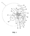
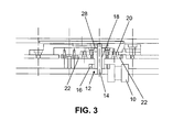
- the correction device 1 also comprises an intermediate connecting member 12, mounted free to rotate about an axis 14 integral with the frame, said connecting member 12 comprising a first toothing, lower, 16 and a second toothing, upper, 18.
- the connecting member 12 is arranged with respect to the transmission pinion 10 so that said transmission gear 10 meshes with the first toothing 16 of the connecting member 12.
- the connecting member 12 is used for time setting, or correction of a time zone, as will be described in more detail below.
- the corrector device 1 also comprises a planet wheel 20, mounted free to rotate about the axis 14.
- the planet carrier wheel 20 carries two satellites 22 mounted free to rotate.
- the satellites 22 are arranged under the planet wheel 20 so that their toothing meshes with the second toothing 18 of the intermediate connecting member 12, independently of the position of the planet carrier wheel 20 and therefore independently of the position of the satellites 22 with respect to the axis of the control rod.
- the number of satellites is not limited to the variant described, and depends on the path that it is desired to make the satellite wheel traverse for a satellite to cooperate with a function corrector. The person skilled in the art knows how to calculate the dimensions and the number of teeth of the various gears to transmit appropriately the rotational movements of the control rod.
- the function correctors 24, 25, 26 are disposed relative to the planet carrier wheel 20 so that the toothing of a satellite 22 cooperates with a function corrector when the satellite 22 is positioned opposite said function corrector.
- one of the function correctors is a time-setting return.
- a first star wheel 28 free to rotate about the axis 14 and integral with said planet carrier wheel 20. Said wheel 28 is used to drive the planet wheel 20 in rotation .
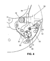
- the corrector device 1 has means for actuating the wheel 28, these actuating means comprising a control lever 30 that can be actuated by means of the pusher and a control lever 32 cooperating with said control rocker 30.
- the control lever 32 is arranged so that its nose cooperates with the toothing of the wheel 28 to actuate said star wheel 28 and cause it to rotate with each pressure on the pusher.
- a spring 34 is provided to return the control lever 32 to its rest position, in which the wheel 28 is not activated.
- a jumper 37 is provided for holding the wheel 28 in position.
- the corrector device 1 comprises a locking device comprising two clamps 35a, 35b having teeth 36 that can engage in correspondingly shaped slots 38 provided on the periphery of the wheel.
- the clamps 35a, 35b are mounted articulated at the same point 40.
- Each clamp has at its end, on the pivot point 40 side, a hook shape 42, said hooks 42 of the two clamps 40 being in position. view to form an entry point for a hammer 44 mounted hinged to the frame and operable via the pusher.
- the hammer 44 is arranged in such a way that it can be actuated by pressing the control rocker 30, itself capable of being actuated by means of the pusher so that the opening of the clamps 35a, 35b is controlled. by pressing on the pusher.
- the locking device further comprises clamp springs 46 arranged to return the clamps 35a, 35b to the notches 36 of the planet carrier wheel 20 when no pressure is applied to the hammer 44.
- the correction device further comprises a winding pinion 50 disposed in known manner on the control rod.
- a mechanism for actuating the sliding pinion 10 comprising a winding latch 51, pivotally mounted on the frame and whose end cooperates with said sliding pinion 10 to move it and mesh with said winding pinion 50.
- This actuating mechanism of the sliding pinion 10 also comprises a winding lever 52 pivotally mounted on the frame and operable by means of the pusher.
- a spring 53 is provided to return the winding lever 52 to its rest position in which no pressure is exerted on the pusher.
- the winding lever 52 is arranged to actuate a winding wheel 54, of the star wheel type, pivotally mounted on the frame.
- the winding wheel 54 is also held in position by means of a jumper 55.
- the winding wheel 54 is integral with a cam 56 having a shape to tilt the winding latch 51 after a number of pressures on the pusher so as to move the sliding pinion 10 against the winding pinion 50.
- the shape the cam 56 also makes it possible to return, using a spring 58, the winding latch 51 and thus the pinion flowing against the intermediate connecting member 12 after a certain number of pressures on the pusher.
- the winding lever 52 is the element directly actuated by the pusher. It further comprises a pin 60 positioned relative to the control lever 30 so that said pin 60 presses said control lever 30 to actuate it in case of pressure on the pusher.
- the corrector device may further comprise an indicator having a kinematic connection with the planet carrier wheel and arranged to display on a dial the selected correction position by means of the satellite.
- the function correctors 24, 25, 26 may be correctors for time setting, date indication, the control rod being in this case a winding stem. It is obvious that the function correctors can correspond to other functions, such as correction functions of the various indications present in a perpetual calendar.
- the corrector device operates as follows: in the neutral position, when no function is activated, the planet carrier wheel 20 is arranged so that the satellites 22 are not in contact with any of the function correctors 24, 25, 26.
- a user wishes, for example, to set his watch on time, he presses the pushbutton a number of times so that the winding lever 52 is actuated.
- the control lever 30 is itself actuated to move both the control lever 30 and the hammer 44.
- the control lever 30 presses the hammer 44 the latter engaged between the hooks 42 of the clamps 35a, 35b force the clamps 35a, 35b to open and to move away from the notches 38 of the planet wheel 20.
- the control lever 32 actuated by the control lever 30 pushes the star wheel 28.
- the planet wheel 20 released from the clamps 35a, 35b can rotate.
- the trajectory of a point on the toothing of the satellites 22 is a circle 65, tangent to the various function correctors 24, 25, 26, and the trajectory of a Another point on the toothing of the satellites 22 is a circle tangential to the second toothing 18 of the connecting member 12.
- the satellites 22 always remain in mesh with the connecting member 12 regardless of the position of the wheel-carrier. 20, and cooperate with one of the function correctors 24, 25, 26 when positioned opposite one of said function correctors 24, 25, 26.
- one of the satellites 22 is positioned with regard to the time correction corrector 25.
- the kinematic connection between the control ring and the time-setting gears 67, 68 is then established.
- the rotation of the control ring successively causes the rotation of the rod, and therefore of the transmission gear 10, then of the connecting member via the first toothing 16 and the satellite 22 via the second gear. 18 and the time correction corrector 25.
- the user presses the pusher again to move the star wheel 28 and thus the planet wheel 20, so to move the satellite 22 so that it no longer cooperates with the time setting corrector 25.
- the pressure on the pusher actuated the winding lever 52 and thus the winding wheel 54 and cam 56.
- the shape of the cam 56 is such that the winding latch 51 remains in position.
- winding latch 51 then pushes the transmission pinion 10 or the pinion flowing against the winding pinion 50.
- the winding of the watch is then done by turning the control crown. Then the user pushes again on the pusher a determined number of times for the cam 56 to reboot the winding latch 51, so that the sliding pinion resumes its position in which it cooperates with the connecting member 12.
- the different springs can bring the various elements back to their rest position.
- the springs 46 return the clamps 35a, 35b so that the teeth 36 of the clamps engage in the notches 38 in correspondence on the planet carrier wheel 20. Said planet carrier wheel 20 is thus perfectly maintained to ensure the good satellite positioning 22.
Landscapes
- Physics & Mathematics (AREA)
- General Physics & Mathematics (AREA)
- Electric Clocks (AREA)
- Electromechanical Clocks (AREA)
Claims (10)
- Multifunktions-Korrekturvorrichtung (1) für eine Uhr, die einen Mittelteil umfasst, die es erlaubt, mit einem einzigen äußeren Steuerorgan, das ausgebildet ist, um auf Ebene des Mittelteils ausgebildet zu sein, eine Funktion aus einer Funktionsgruppe auszuwählen und/oder zu ändern, wobei das Steuerorgan eine Steuerkrone, einen zur Steuerkrone koaxialen Drücker und eine mit der Steuerkrone verbundene Steuerwelle umfasst, wobei die Korrekturvorrichtung ferner umfasst:- einen mit der Steuerwelle rotierend verbundenen Übertragungstrieb (10),- ein zwischengestelltes Verbindungsorgan (12), das frei drehend um eine Achse (14) montiert ist, wobei das Verbindungsorgan (12) eine erste (16) und eine zweite (18) Zahnung umfasst, wobei die erste Zahnung (16) mit dem Übertragungstrieb (10) zusammenarbeitet,
dadurch gekennzeichnet, dass die Korrekturvorrichtung ferner umfasst:- ein planetenradtragendes Rad (20), das frei drehend koaxial zum Verbindungsorgan (12) montiert ist und mindestens ein frei drehendes Planetenrad (22) trägt, wobei das Planetenrad (22) im Verhältnis zum Verbindungsorgan (12) derart ausgebildet ist, dass es immer mit der zweiten Zahnung (18) des Verbindungsorgans (12) zusammenarbeitet, unabhängig von der Position des planetenradtragenden Rads (20), wobei das planetenradtragende Rad (20) ferner auf seinem Umfang Kerben (38) aufweist,- ein Sternrad (28), das frei drehend koaxial zum Verbindungsorgan (12) montiert ist und ausgebildet, um mit dem planetenradtragenden Rad (20) verbunden zu sein,- eine Blockiervorrichtung des planetenradtragenden Rads (20), die ausgebildet ist, um von dem Drücker betätigt zu sein, wobei die Blockiervorrichtung Zangen (35a, 35b) umfasst, die imstande sind, sich in den Kerben (38) zu platzieren, um das planetenradtragende Rad (20) zu blockieren, und sich aus den Kerben (38) zu lösen, um das planetenradtragende Rad (20) freizugeben, und- Betätigungsmittel des Sternrads (28), die ausgebildet sind, um von dem Drücker derart betätigt zu sein, dass es ein oder mehrere Drücke auf den Drücker erlauben, das Planetenrad (22) zu verlagern, um es gegenüber einem Funktionskorrektor (24, 25, 26) zu positionieren, der der ausgewählten Funktion entspricht, um die Funktion durch Drehen der Steuerkrone zu aktivieren und/oder zu ändern. - Korrekturvorrichtung nach Anspruch 1, dadurch gekennzeichnet, dass die Betätigungsmittel des Sternrads (28) eine Steuerwippe (30) umfassen, die imstande ist, über den Drücker und einen Steuerhebel (32) betätigt zu sein, der mit der Steuerwippe (30) zusammenarbeitet, wobei der Steuerhebel (32) ausgebildet ist, um das Sternrad (28) zu betätigen und bei jedem Druck auf den Drücker rotierend anzutreiben.
- Korrekturvorrichtung nach Anspruch 2, dadurch gekennzeichnet, dass die Zangen (35a, 35b) der Blockiervorrichtung in einem Punkt (40) angelenkt sind und dass die Blockiervorrichtung einen Hammer (44) umfasst, der imstande ist, über den Drücker betätigt zu sein, wobei die Enden der Zangen (35a, 35b) einen Eingangspunkt für den Hammer (44) bilden, um die Zangen (35a, 35b) bei jedem Schlag des Hammers (44) bei jedem Druck auf den Drücker zu spreizen.
- Korrekturvorrichtung nach Anspruch 3, dadurch gekennzeichnet, dass die Blockiervorrichtung ferner Zangenfedern (46) umfasst, die ausgebildet sind, um die Zangen (35a, 35b) in die Kerben (38) des planetenradtragenden Rads (20) zu führen.
- Korrekturvorrichtung nach einem der vorangehenden Ansprüche, dadurch gekennzeichnet, dass der Übertragungstrieb (10) ein Kupplungstrieb ist, der sich auf der Steuerwelle verlagert und dass das zwischengestellte Verbindungsorgan (12) zum Zeigerstellen verwendet wird und dass der Funktionskorrektor (25) ein Zeigerstell-Vorgelege ist.
- Korrekturvorrichtung nach Anspruch 5, dadurch gekennzeichnet, dass sie ferner einen Aufzugtrieb (50) umfasst, der auf der Steuerwelle angeordnet ist und einen Betätigungsmechanismus des Kupplungstriebs, um zu erlauben, dass er mit dem Aufzugtrieb (50) zusammenarbeitet und das Aufziehen eines Uhrwerks zu erlauben.
- Korrekturvorrichtung nach Anspruch 6, dadurch gekennzeichnet, dass der Betätigungsmechanismus des Kupplungstriebs einen Aufzughebel (52) umfasst, der imstande ist, über den Drücker betätigt zu sein, ein Aufzugrad (54), das ausgebildet ist, um von dem Aufzughebel (52) betätigt zu sein, wobei das Aufzugrad (54) eine Kurvenscheibe (56) trägt, und eine Aufzugwippe (51), die ausgebildet ist, um einerseits von der Kurvenscheibe (56) angetrieben zu sein und um andererseits mit dem Kupplungstrieb zusammenzuarbeiten, wobei die Kurvenscheibe (56) eine Form aufweist, die es erlaubt, dass die Aufzugwippe (51) wippt und sich der Kupplungstrieb nach einer bestimmten Anzahl von Drücken auf den Drücker gegen den Aufzugtrieb (50) verlagert und die Aufzugwippe (51) und den Kupplungstrieb nach einer bestimmten Anzahl von Drücken auf den Drücker gegen das Verbindungsorgan (12) zurückzuführen.
- Korrekturvorrichtung nach Anspruch 7, dadurch gekennzeichnet, dass entweder der Aufzughebel (52) oder die Steuerwippe (30) einen Stift (60) umfasst, der ausgebildet ist, um beim Drücken des Drückers entweder den Aufzughebel (52) oder Steuerwippe (30) zu betätigen.
- Korrekturvorrichtung nach einem der vorangehenden Ansprüche, dadurch gekennzeichnet, dass sie ferner einen Anzeiger umfasst, der eine kinematische Verbindung mit dem planetenradtragenden Rad (20) hat und ausgebildet ist, um auf einem Zifferblatt die mit Hilfe des Planetenrads ausgewählte Korrekturposition anzuzeigen.
- Uhr, die ein mechanisches Uhrwerk enthält, dadurch gekennzeichnet, dass sie eine Korrekturvorrichtung nach einem der Ansprüche 1 bis 9 aufweist.
Applications Claiming Priority (1)
| Application Number | Priority Date | Filing Date | Title |
|---|---|---|---|
| CH3682010A CH702841B1 (fr) | 2010-03-16 | 2010-03-16 | Dispositif correcteur multifonction et pièce d'horlogerie comprenant un tel dispositif correcteur. |
Publications (2)
| Publication Number | Publication Date |
|---|---|
| EP2367074A1 EP2367074A1 (de) | 2011-09-21 |
| EP2367074B1 true EP2367074B1 (de) | 2013-01-16 |
Family
ID=42232695
Family Applications (1)
| Application Number | Title | Priority Date | Filing Date |
|---|---|---|---|
| EP20110153380 Active EP2367074B1 (de) | 2010-03-16 | 2011-02-04 | Multifunktionsvorrichtung zur Korrektur und Uhr mit dieser Vorrichtung. |
Country Status (2)
| Country | Link |
|---|---|
| EP (1) | EP2367074B1 (de) |
| CH (1) | CH702841B1 (de) |
Families Citing this family (6)
| Publication number | Priority date | Publication date | Assignee | Title |
|---|---|---|---|---|
| EP2701015B1 (de) * | 2012-08-21 | 2018-11-14 | Blancpain SA. | Vorrichtung zur Korrektur der von einer Uhr angezeigten Funktionen |
| CH707870B1 (fr) * | 2013-04-08 | 2017-07-14 | Gfpi S A | Mécanisme de sélection et d'actionnement des fonctions d'un mouvement horloger et pièce d'horlogerie comprenant un tel mécanisme. |
| CH709758A2 (fr) * | 2014-06-13 | 2015-12-15 | Kari Voutilainen | Mécanisme de chronographe avec un organe de commande multifonctions, notamment pour un retour-en-vol («flyback»). |
| CH710647A2 (fr) * | 2015-01-23 | 2016-07-29 | Helinov Sa | Organe de remontage et/ou de mise à l'heure destiné à la commande d'un mouvement et montre comportant un tel organe. |
| CN114442465B (zh) | 2015-04-01 | 2024-10-25 | 劳力士有限公司 | 允许对至少一种钟表功能进行上发条和/或校正的机构、手表机芯及手表 |
| CN108714671A (zh) * | 2018-06-11 | 2018-10-30 | 江苏省溧水弹簧厂(普通合伙) | 一种弹簧加工用校正设备 |
Family Cites Families (6)
| Publication number | Priority date | Publication date | Assignee | Title |
|---|---|---|---|---|
| CH173454A (fr) * | 1934-02-02 | 1934-11-30 | Ingold Robert | Montre. |
| JPS4924696B1 (de) * | 1970-02-27 | 1974-06-25 | ||
| CH534381A (fr) * | 1971-02-08 | 1972-09-15 | Ebauches S A 1 Faubourg De L H | Pièce d'horlogerie |
| CH645235GA3 (de) * | 1981-04-23 | 1984-09-28 | ||
| US6711099B1 (en) * | 2001-04-10 | 2004-03-23 | Watch-U-License Ag | Setting and winding mechanism |
| EP1939699B1 (de) * | 2006-12-29 | 2012-05-30 | Montres Breguet S.A. | Multifunktionsvorrichtung zur koaxialen Korrektur |
-
2010
- 2010-03-16 CH CH3682010A patent/CH702841B1/fr not_active IP Right Cessation
-
2011
- 2011-02-04 EP EP20110153380 patent/EP2367074B1/de active Active
Also Published As
| Publication number | Publication date |
|---|---|
| CH702841A1 (fr) | 2011-09-30 |
| EP2367074A1 (de) | 2011-09-21 |
| CH702841B1 (fr) | 2014-11-14 |
Similar Documents
| Publication | Publication Date | Title |
|---|---|---|
| EP2984526B1 (de) | Vorrichtung zur auswahl und betätigung der funktionen eines uhrwerks | |
| EP2367074A1 (de) | Multifunktionsvorrichtung zur Korrektur und Uhr mit dieser Vorrichtung. | |
| CH702548B1 (fr) | Mécanisme de sélection de fonction pour mouvement d'horlogerie comportant au moins une complication. | |
| WO2016155814A1 (fr) | Mécanisme de remontage et/ou de correction d'au moins une fonction horlogère et dispositif de sélection d'une fonction horlogère | |
| EP1544691B1 (de) | Uhr, deren Stundenzeiger durch Stundenschritten vor- oder zurückspringen kann | |
| CH702803A2 (fr) | Mecanisme de correction d'au moins deux informations affichees autres que l'heure courante, pour mouvement horloger. | |
| EP3882718B1 (de) | Korrekturvorrichtung mindestens einer komplikation einer uhr | |
| EP4295198B1 (de) | Element zur steuerung mehrerer funktionen eines uhrwerks | |
| EP4270114B1 (de) | Vorrichtung zum auswählen und betätigen mehrerer funktionen eines uhrwerks | |
| EP3584643B1 (de) | Augenblicklich schaltende steuervorrichtung für datumsanzeige von uhren | |
| CH699794B1 (fr) | Dispositif d'aide au maintien en position d'un anneau indicateur de quantième pour pièce d'horlogerie. | |
| EP2279460A1 (de) | Uhrmechanismus und modul mit derartigem mechanismus | |
| CH717217A2 (fr) | Mécanisme de réglage de balancier à même de redémarrer le fonctionnement du balancier, mouvement et pièce d'horlogerie le comprenant. | |
| EP3486733B1 (de) | Steuervorrichtung für uhr, die ein schaltrad umfasst | |
| EP2281222B1 (de) | Anzeigevorrichtung | |
| EP2802945A1 (de) | Uhrwerkbewegungsanzeigemechanismus, der in abhängigkeit von einer informationsanfrage funktioniert | |
| EP1316863A1 (de) | Formuhrwerk mit Chronograph | |
| EP1366471B1 (de) | Mechanische uhr mit anzeige der wöchentlichen zyklen | |
| EP4462192B1 (de) | Anzeigevorrichtung für uhrwerk | |
| WO2025126100A1 (fr) | Dispositif de sélection et d'actionnement d'au moins deux fonctions d'un mouvement d'horlogerie | |
| CH720984B1 (fr) | Mécanisme de commande pour pièce d'horlogerie | |
| CH718698B1 (fr) | Mécanisme horloger pour correction de plusieurs affichages. | |
| CH718429B1 (fr) | Mécanisme de correction d'indicateur, mécanisme d'indication d'informations, mouvement, et pièce d'horlogerie | |
| EP4071561A1 (de) | Repetitionsuhr | |
| FR2492999A1 (fr) | Dispositif mecanique de mise a l'heure d'une montre a affichage analogique |
Legal Events
| Date | Code | Title | Description |
|---|---|---|---|
| PUAI | Public reference made under article 153(3) epc to a published international application that has entered the european phase |
Free format text: ORIGINAL CODE: 0009012 |
|
| AK | Designated contracting states |
Kind code of ref document: A1 Designated state(s): AL AT BE BG CH CY CZ DE DK EE ES FI FR GB GR HR HU IE IS IT LI LT LU LV MC MK MT NL NO PL PT RO RS SE SI SK SM TR |
|
| AX | Request for extension of the european patent |
Extension state: BA ME |
|
| 17P | Request for examination filed |
Effective date: 20120315 |
|
| RIC1 | Information provided on ipc code assigned before grant |
Ipc: G04B 27/00 20060101ALI20120531BHEP Ipc: G04B 3/04 20060101AFI20120531BHEP |
|
| REG | Reference to a national code |
Ref country code: HK Ref legal event code: DE Ref document number: 1164468 Country of ref document: HK |
|
| GRAP | Despatch of communication of intention to grant a patent |
Free format text: ORIGINAL CODE: EPIDOSNIGR1 |
|
| GRAS | Grant fee paid |
Free format text: ORIGINAL CODE: EPIDOSNIGR3 |
|
| GRAA | (expected) grant |
Free format text: ORIGINAL CODE: 0009210 |
|
| AK | Designated contracting states |
Kind code of ref document: B1 Designated state(s): AL AT BE BG CH CY CZ DE DK EE ES FI FR GB GR HR HU IE IS IT LI LT LU LV MC MK MT NL NO PL PT RO RS SE SI SK SM TR |
|
| REG | Reference to a national code |
Ref country code: GB Ref legal event code: FG4D Free format text: NOT ENGLISH |
|
| REG | Reference to a national code |
Ref country code: CH Ref legal event code: EP |
|
| REG | Reference to a national code |
Ref country code: IE Ref legal event code: FG4D Free format text: LANGUAGE OF EP DOCUMENT: FRENCH |
|
| REG | Reference to a national code |
Ref country code: AT Ref legal event code: REF Ref document number: 594185 Country of ref document: AT Kind code of ref document: T Effective date: 20130215 Ref country code: CH Ref legal event code: EP |
|
| REG | Reference to a national code |
Ref country code: DE Ref legal event code: R096 Ref document number: 602011000744 Country of ref document: DE Effective date: 20130314 |
|
| REG | Reference to a national code |
Ref country code: CH Ref legal event code: NV Representative=s name: GLN S.A., CH |
|
| REG | Reference to a national code |
Ref country code: AT Ref legal event code: MK05 Ref document number: 594185 Country of ref document: AT Kind code of ref document: T Effective date: 20130116 |
|
| REG | Reference to a national code |
Ref country code: NL Ref legal event code: VDEP Effective date: 20130116 |
|
| REG | Reference to a national code |
Ref country code: LT Ref legal event code: MG4D |
|
| PG25 | Lapsed in a contracting state [announced via postgrant information from national office to epo] |
Ref country code: IS Free format text: LAPSE BECAUSE OF FAILURE TO SUBMIT A TRANSLATION OF THE DESCRIPTION OR TO PAY THE FEE WITHIN THE PRESCRIBED TIME-LIMIT Effective date: 20130516 Ref country code: NO Free format text: LAPSE BECAUSE OF FAILURE TO SUBMIT A TRANSLATION OF THE DESCRIPTION OR TO PAY THE FEE WITHIN THE PRESCRIBED TIME-LIMIT Effective date: 20130416 Ref country code: AT Free format text: LAPSE BECAUSE OF FAILURE TO SUBMIT A TRANSLATION OF THE DESCRIPTION OR TO PAY THE FEE WITHIN THE PRESCRIBED TIME-LIMIT Effective date: 20130116 Ref country code: BG Free format text: LAPSE BECAUSE OF FAILURE TO SUBMIT A TRANSLATION OF THE DESCRIPTION OR TO PAY THE FEE WITHIN THE PRESCRIBED TIME-LIMIT Effective date: 20130416 Ref country code: ES Free format text: LAPSE BECAUSE OF FAILURE TO SUBMIT A TRANSLATION OF THE DESCRIPTION OR TO PAY THE FEE WITHIN THE PRESCRIBED TIME-LIMIT Effective date: 20130427 Ref country code: SE Free format text: LAPSE BECAUSE OF FAILURE TO SUBMIT A TRANSLATION OF THE DESCRIPTION OR TO PAY THE FEE WITHIN THE PRESCRIBED TIME-LIMIT Effective date: 20130116 Ref country code: LT Free format text: LAPSE BECAUSE OF FAILURE TO SUBMIT A TRANSLATION OF THE DESCRIPTION OR TO PAY THE FEE WITHIN THE PRESCRIBED TIME-LIMIT Effective date: 20130116 |
|
| PG25 | Lapsed in a contracting state [announced via postgrant information from national office to epo] |
Ref country code: LV Free format text: LAPSE BECAUSE OF FAILURE TO SUBMIT A TRANSLATION OF THE DESCRIPTION OR TO PAY THE FEE WITHIN THE PRESCRIBED TIME-LIMIT Effective date: 20130116 Ref country code: FI Free format text: LAPSE BECAUSE OF FAILURE TO SUBMIT A TRANSLATION OF THE DESCRIPTION OR TO PAY THE FEE WITHIN THE PRESCRIBED TIME-LIMIT Effective date: 20130116 Ref country code: SI Free format text: LAPSE BECAUSE OF FAILURE TO SUBMIT A TRANSLATION OF THE DESCRIPTION OR TO PAY THE FEE WITHIN THE PRESCRIBED TIME-LIMIT Effective date: 20130116 Ref country code: PL Free format text: LAPSE BECAUSE OF FAILURE TO SUBMIT A TRANSLATION OF THE DESCRIPTION OR TO PAY THE FEE WITHIN THE PRESCRIBED TIME-LIMIT Effective date: 20130116 Ref country code: PT Free format text: LAPSE BECAUSE OF FAILURE TO SUBMIT A TRANSLATION OF THE DESCRIPTION OR TO PAY THE FEE WITHIN THE PRESCRIBED TIME-LIMIT Effective date: 20130516 Ref country code: GR Free format text: LAPSE BECAUSE OF FAILURE TO SUBMIT A TRANSLATION OF THE DESCRIPTION OR TO PAY THE FEE WITHIN THE PRESCRIBED TIME-LIMIT Effective date: 20130417 Ref country code: NL Free format text: LAPSE BECAUSE OF FAILURE TO SUBMIT A TRANSLATION OF THE DESCRIPTION OR TO PAY THE FEE WITHIN THE PRESCRIBED TIME-LIMIT Effective date: 20130116 |
|
| BERE | Be: lapsed |
Owner name: VOUTILAINEN, KARI Effective date: 20130228 |
|
| PG25 | Lapsed in a contracting state [announced via postgrant information from national office to epo] |
Ref country code: RS Free format text: LAPSE BECAUSE OF FAILURE TO SUBMIT A TRANSLATION OF THE DESCRIPTION OR TO PAY THE FEE WITHIN THE PRESCRIBED TIME-LIMIT Effective date: 20130116 Ref country code: HR Free format text: LAPSE BECAUSE OF FAILURE TO SUBMIT A TRANSLATION OF THE DESCRIPTION OR TO PAY THE FEE WITHIN THE PRESCRIBED TIME-LIMIT Effective date: 20130116 Ref country code: MC Free format text: LAPSE BECAUSE OF NON-PAYMENT OF DUE FEES Effective date: 20130228 |
|
| PG25 | Lapsed in a contracting state [announced via postgrant information from national office to epo] |
Ref country code: DK Free format text: LAPSE BECAUSE OF FAILURE TO SUBMIT A TRANSLATION OF THE DESCRIPTION OR TO PAY THE FEE WITHIN THE PRESCRIBED TIME-LIMIT Effective date: 20130116 Ref country code: SK Free format text: LAPSE BECAUSE OF FAILURE TO SUBMIT A TRANSLATION OF THE DESCRIPTION OR TO PAY THE FEE WITHIN THE PRESCRIBED TIME-LIMIT Effective date: 20130116 Ref country code: RO Free format text: LAPSE BECAUSE OF FAILURE TO SUBMIT A TRANSLATION OF THE DESCRIPTION OR TO PAY THE FEE WITHIN THE PRESCRIBED TIME-LIMIT Effective date: 20130116 Ref country code: CZ Free format text: LAPSE BECAUSE OF FAILURE TO SUBMIT A TRANSLATION OF THE DESCRIPTION OR TO PAY THE FEE WITHIN THE PRESCRIBED TIME-LIMIT Effective date: 20130116 Ref country code: EE Free format text: LAPSE BECAUSE OF FAILURE TO SUBMIT A TRANSLATION OF THE DESCRIPTION OR TO PAY THE FEE WITHIN THE PRESCRIBED TIME-LIMIT Effective date: 20130116 |
|
| PLBE | No opposition filed within time limit |
Free format text: ORIGINAL CODE: 0009261 |
|
| STAA | Information on the status of an ep patent application or granted ep patent |
Free format text: STATUS: NO OPPOSITION FILED WITHIN TIME LIMIT |
|
| PG25 | Lapsed in a contracting state [announced via postgrant information from national office to epo] |
Ref country code: CY Free format text: LAPSE BECAUSE OF FAILURE TO SUBMIT A TRANSLATION OF THE DESCRIPTION OR TO PAY THE FEE WITHIN THE PRESCRIBED TIME-LIMIT Effective date: 20130116 |
|
| REG | Reference to a national code |
Ref country code: IE Ref legal event code: MM4A |
|
| 26N | No opposition filed |
Effective date: 20131017 |
|
| PG25 | Lapsed in a contracting state [announced via postgrant information from national office to epo] |
Ref country code: IT Free format text: LAPSE BECAUSE OF FAILURE TO SUBMIT A TRANSLATION OF THE DESCRIPTION OR TO PAY THE FEE WITHIN THE PRESCRIBED TIME-LIMIT Effective date: 20130116 |
|
| PG25 | Lapsed in a contracting state [announced via postgrant information from national office to epo] |
Ref country code: IE Free format text: LAPSE BECAUSE OF NON-PAYMENT OF DUE FEES Effective date: 20130204 Ref country code: AL Free format text: LAPSE BECAUSE OF FAILURE TO SUBMIT A TRANSLATION OF THE DESCRIPTION OR TO PAY THE FEE WITHIN THE PRESCRIBED TIME-LIMIT Effective date: 20130116 Ref country code: BE Free format text: LAPSE BECAUSE OF NON-PAYMENT OF DUE FEES Effective date: 20130228 |
|
| REG | Reference to a national code |
Ref country code: DE Ref legal event code: R097 Ref document number: 602011000744 Country of ref document: DE Effective date: 20131017 |
|
| PG25 | Lapsed in a contracting state [announced via postgrant information from national office to epo] |
Ref country code: MT Free format text: LAPSE BECAUSE OF FAILURE TO SUBMIT A TRANSLATION OF THE DESCRIPTION OR TO PAY THE FEE WITHIN THE PRESCRIBED TIME-LIMIT Effective date: 20130116 |
|
| PG25 | Lapsed in a contracting state [announced via postgrant information from national office to epo] |
Ref country code: SM Free format text: LAPSE BECAUSE OF FAILURE TO SUBMIT A TRANSLATION OF THE DESCRIPTION OR TO PAY THE FEE WITHIN THE PRESCRIBED TIME-LIMIT Effective date: 20130116 |
|
| PG25 | Lapsed in a contracting state [announced via postgrant information from national office to epo] |
Ref country code: TR Free format text: LAPSE BECAUSE OF FAILURE TO SUBMIT A TRANSLATION OF THE DESCRIPTION OR TO PAY THE FEE WITHIN THE PRESCRIBED TIME-LIMIT Effective date: 20130116 |
|
| PG25 | Lapsed in a contracting state [announced via postgrant information from national office to epo] |
Ref country code: HU Free format text: LAPSE BECAUSE OF FAILURE TO SUBMIT A TRANSLATION OF THE DESCRIPTION OR TO PAY THE FEE WITHIN THE PRESCRIBED TIME-LIMIT; INVALID AB INITIO Effective date: 20110204 Ref country code: MK Free format text: LAPSE BECAUSE OF FAILURE TO SUBMIT A TRANSLATION OF THE DESCRIPTION OR TO PAY THE FEE WITHIN THE PRESCRIBED TIME-LIMIT Effective date: 20130116 Ref country code: LU Free format text: LAPSE BECAUSE OF NON-PAYMENT OF DUE FEES Effective date: 20130204 |
|
| REG | Reference to a national code |
Ref country code: FR Ref legal event code: PLFP Year of fee payment: 6 |
|
| PGFP | Annual fee paid to national office [announced via postgrant information from national office to epo] |
Ref country code: GB Payment date: 20160226 Year of fee payment: 6 Ref country code: FR Payment date: 20160217 Year of fee payment: 6 |
|
| REG | Reference to a national code |
Ref country code: CH Ref legal event code: PFA Owner name: VOUTILAINEN, KARI, CH Free format text: FORMER OWNER: VOUTILAINEN, KARI, CH |
|
| GBPC | Gb: european patent ceased through non-payment of renewal fee |
Effective date: 20170204 |
|
| REG | Reference to a national code |
Ref country code: FR Ref legal event code: ST Effective date: 20171031 |
|
| PG25 | Lapsed in a contracting state [announced via postgrant information from national office to epo] |
Ref country code: FR Free format text: LAPSE BECAUSE OF NON-PAYMENT OF DUE FEES Effective date: 20170228 |
|
| PG25 | Lapsed in a contracting state [announced via postgrant information from national office to epo] |
Ref country code: GB Free format text: LAPSE BECAUSE OF NON-PAYMENT OF DUE FEES Effective date: 20170204 |
|
| REG | Reference to a national code |
Ref country code: HK Ref legal event code: WD Ref document number: 1164468 Country of ref document: HK |
|
| REG | Reference to a national code |
Ref country code: CH Ref legal event code: NV Representative=s name: BOVARD SA NEUCHATEL CONSEILS EN PROPRIETE INTE, CH |
|
| REG | Reference to a national code |
Ref country code: CH Ref legal event code: R18 Free format text: ST27 STATUS EVENT CODE: U-0-0-R10-R18 (AS PROVIDED BY THE NATIONAL OFFICE) Effective date: 20260209 |
|
| REG | Reference to a national code |
Ref country code: CH Ref legal event code: U11 Free format text: ST27 STATUS EVENT CODE: U-0-0-U10-U11 (AS PROVIDED BY THE NATIONAL OFFICE) Effective date: 20260301 |
|
| REG | Reference to a national code |
Ref country code: CH Ref legal event code: R18 Free format text: ST27 STATUS EVENT CODE: U-0-0-R10-R18 (AS PROVIDED BY THE NATIONAL OFFICE) Effective date: 20260320 |
|
| PGFP | Annual fee paid to national office [announced via postgrant information from national office to epo] |
Ref country code: DE Payment date: 20260218 Year of fee payment: 16 |
|
| PGFP | Annual fee paid to national office [announced via postgrant information from national office to epo] |
Ref country code: CH Payment date: 20260301 Year of fee payment: 16 |