EP2367085A1 - Dispositif de réglage de la marche pour une installation de transport à un ou deux tours et procédé de réalisation du réglage de la marche - Google Patents
Dispositif de réglage de la marche pour une installation de transport à un ou deux tours et procédé de réalisation du réglage de la marche Download PDFInfo
- Publication number
- EP2367085A1 EP2367085A1 EP10075751A EP10075751A EP2367085A1 EP 2367085 A1 EP2367085 A1 EP 2367085A1 EP 10075751 A EP10075751 A EP 10075751A EP 10075751 A EP10075751 A EP 10075751A EP 2367085 A1 EP2367085 A1 EP 2367085A1
- Authority
- EP
- European Patent Office
- Prior art keywords
- speed
- monitoring
- programmable logic
- conveyor
- plc
- Prior art date
- Legal status (The legal status is an assumption and is not a legal conclusion. Google has not performed a legal analysis and makes no representation as to the accuracy of the status listed.)
- Withdrawn
Links
Images






Classifications
-
- G—PHYSICS
- G05—CONTROLLING; REGULATING
- G05B—CONTROL OR REGULATING SYSTEMS IN GENERAL; FUNCTIONAL ELEMENTS OF SUCH SYSTEMS; MONITORING OR TESTING ARRANGEMENTS FOR SUCH SYSTEMS OR ELEMENTS
- G05B19/00—Program-control systems
- G05B19/02—Program-control systems electric
- G05B19/04—Program control other than numerical control, i.e. in sequence controllers or logic controllers
- G05B19/05—Programmable logic controllers, e.g. simulating logic interconnections of signals according to ladder diagrams or function charts
- G05B19/058—Safety, monitoring
-
- G—PHYSICS
- G05—CONTROLLING; REGULATING
- G05B—CONTROL OR REGULATING SYSTEMS IN GENERAL; FUNCTIONAL ELEMENTS OF SUCH SYSTEMS; MONITORING OR TESTING ARRANGEMENTS FOR SUCH SYSTEMS OR ELEMENTS
- G05B2219/00—Program-control systems
- G05B2219/10—Plc systems
- G05B2219/14—Plc safety
- G05B2219/14014—Redundant processors and I-O
-
- G—PHYSICS
- G05—CONTROLLING; REGULATING
- G05B—CONTROL OR REGULATING SYSTEMS IN GENERAL; FUNCTIONAL ELEMENTS OF SUCH SYSTEMS; MONITORING OR TESTING ARRANGEMENTS FOR SUCH SYSTEMS OR ELEMENTS
- G05B2219/00—Program-control systems
- G05B2219/20—Pc systems
- G05B2219/26—Pc applications
- G05B2219/2659—Elevator
-
- G—PHYSICS
- G05—CONTROLLING; REGULATING
- G05B—CONTROL OR REGULATING SYSTEMS IN GENERAL; FUNCTIONAL ELEMENTS OF SUCH SYSTEMS; MONITORING OR TESTING ARRANGEMENTS FOR SUCH SYSTEMS OR ELEMENTS
- G05B2219/00—Program-control systems
- G05B2219/30—Nc systems
- G05B2219/45—Nc applications
- G05B2219/45014—Elevator, lift
Definitions
- the invention relates to a device for controlling the travel of a single or double feed conveyor according to the preamble of claim 1.
- the invention further relates to a method for executing a cruise control for such a conveyor according to the preamble of claim 10.
- Such conveyor systems are mainly operated in mining facilities. They are used to carry loads and / or people in vertical wells. These systems have a travel speed of up to 10 m / s. They are usually designed as traction sheave or double drum systems with or without hiding.
- a first mode of operation is given in particular by a freight promotion
- a second mode of operation by a promotion of persons.
- These differ in particular by different driving behavior of the conveyor system for example, different acceleration or deceleration values in the end sections of the shaft or different speeds in the shaft itself. It has been shown in the operation of such conveyor systems that an automatic driving control, which is particularly used in a freight promotion , is disadvantageous in other modes of operation of the plant.
- the object is achieved in its device aspect with a device for driving control for a single or double-struck conveyor system with the features of claim 1.
- the object is achieved with a method for controlling the travel of a single or double-struck conveyor system with the features of claim 10.
- the apparatus includes a cruise control unit comprising at least a first programmable logic control system for forming a guidance and monitoring part for executing control for a carrier and a second programmable logic controller for forming a redundant second guidance and monitoring part.
- signal generators for a driving speed and signal transmitters for a travel path are provided on a drive side of a cable carrier and / or on the cable carrier.
- the inventive idea is to use a programmable logic control system for cruise control.
- a programmable logic control system for cruise control.
- Such a system has the advantage that the manner of the cruise control in a simple manner by means of programming can be predetermined.
- driving parameters which, even in the case of manual operation, ensure that dangerous parameters for driving safety are not exceeded.
- the programmable logic controller is redundant.
- a second programmable logic control system is provided. This ensures that the operating parameters captured by both control systems are equally processed correctly.
- the first programmable logic controller system and the second programmable logic controller Control system from each other differently formed processor units and operating systems. This ensures that technical defects or undetected programming errors are likely to occur only in one of the two control systems but not in both in the same way.
- the first and second programmable logic controller systems are interconnected via a DP / DP coupler unit.
- the DP / DP coupler unit realizes an existing between the control systems fieldbus. Such a connection relies on a proven and secure transmission protocol.
- a mains voltage independent tachogenerator As a signal generator for a driving speed a mains voltage independent tachogenerator is provided. This is equipped with a threshold for detecting an overspeed. The tachogenerator provides a voltage signal corresponding to the current speed. This data acquisition does not require an external power supply. The threshold value switch outputs a separate measurement signal when a speed value lying above a given limit is reached.
- a point-by-point speed monitoring system having a check device which can be activated without reaction and with a shaft switch arrangement mounted in a tripping and / or deceleration area.
- the conveying speed can be determined and monitored on the track itself.
- an angle step encoder is provided in an expedient embodiment, with which the track can be precisely detected.
- the first and the second programmable logic control system each have an output and an input for a signal exchange for a mutual synchronization monitoring. In this way diverging control processes within the control systems can be detected and any resulting hazards can be avoided in the beginning.
- a method of executing cruise control for a single or double feed mill is characterized by using a dual channel, multi-purpose evaluation system with hardware distinct programmable logic control systems to operate one partial safety circuit each.
- Each partial safety circuit is integrated into a safety circuit of the conveyor system via separate contactor contacts. Both channels of the evaluation system exchange signals via a DP / DP link.
- a point-by-point speed monitoring and / or a generation of speed-dependent voltage signals by means of tachogenerators takes place for monitoring a travel speed within a shaft.
- a pigeon-dependent speed for each channel of the evaluation system is calculated and compared for each programmable logic control system.
- setpoint speed values are calculated by each programmable logic control system during execution of the method. These are output to a power part of a drive device.
- the calculation of the setpoint speed values is effected by generating pave-dependent skid curves and / or setpoint values for a speed of the drive and / or a monitoring curve for continuous speed monitoring. This is carried out by generating a set of rate-dependent setpoint speed substraights each having one offset parameter and one slope parameter each. In this case, the one pitch parameter and the one offset parameter for each target speed substraight are calculated redundantly in each programmable logic control system and monitored for equality.
- the speed setpoints calculated with the nominal speed substraction are normalized and transferred to a drive controller as the power unit of the drive device.
- the monitoring curve is calculated in an expedient embodiment of the Abgreskurve by scaling.
- a measured actual speed is compared dynamically with the values of the monitoring curve. If the actual speed is exceeded, finally a safety brake is triggered.
- the Abberichtkurve thus describes an absolute limit for the monitoring of the actual speed of the conveyor system.
- the monitoring curve introduces an additional safety tolerance. This is required in order to gain additional scope for the response of the safety brake and at the same time to ensure that the limit range of the control defined by the diversion curve is never exceeded.
- a carrier which is designed as a double-pulley traction sheave with a first strand and a second strand.
- Each course has a conveyor basket, which can be divided into several floors.
- One of the two conveyor baskets is struck on an oversize rope.
- Fig. 1 shows an overview of the cruise control device.
- the cruise control device comprises a cruise control unit 1 from a first programmable logic control system 2 and a second programmable logic control system 3. These form mutually redundant management and monitoring parts of the cruise control device.
- SPS programmable logic control systems
- Each of the two PLCs receives signals via input modules or a distributed I / O via a dedicated DP bus.
- the calculated sizes of the individual PLCs are exchanged under the PLC via a coupling between them.
- the output signals generated by the PLC are transferred into the safety circuit with effect. Conveniently, it relies on contactor contacts or relays, which are connected to the binary inputs and outputs of the other PLC.
- the PLC check the synchronization and the plausibility of the signals.
- Both the first SPS 2 and the second PLC 3 are connected to vehicle speed signalers 4 and to guideways 5, and output control signals to dedicated parts of a carrier 6. Both PLCs are thus components each a switched between the signal generator 4 and 5 and the carrier 6 partial safety circuit.
- a DP / DP coupler unit 7 is provided between the first PLC 2 and the second PLC 3. This enables a signal exchange between the first PLC and the second PLC.
- Each DP bus is designed separately for each PLC.
- the only connection between the PLC is implemented via a so-called DP / DP coupler. If a component fails within the DP bus, a PLC stop signal is generated. The output relays of the PLC drop out, whereby a safety brake of the conveyor system is applied due to the quiescent current principle.
- the arrangement thus formed forms a two-channel evaluation system.
- This evaluation system is expediently diversified.
- different hardware is used for the first PLC 2 and the second PLC 3.
- the PLC 2 can be implemented as a control system of the type S7-400 and the PLC 3 as a control system of the type S7-300 from Siemens.
- Both channels thus each form a partial safety circuit implemented via the two PLCs. This is implemented by software in each of the two PLCs. Both channels are each incorporated via separate relay contacts in a given safety circuit of the carrier.
- connection of the two PLC with the peripheral components 4, 5 and 6 is advantageously carried out via a bus transmission system.
- a Profibus-DP connection is used.
- WAGO terminals for digital and analog signals can be used as controller boards for the peripherals.
- the bus systems are hardware-identical, ie homogeneous.
- Fig. 2 shows an overview of signaling components for vehicle speed and travel.
- a signaling components for the driving speed 4 a tachogenerator 8 with a threshold value 9 is provided on the one hand.
- the tachogenerator operates independent of mains voltage.
- the threshold switch is used to signal an overspeed.
- a shaft switch assembly 10 is used. This forms a point-by-point speed monitoring device which is used to monitor the driving speed during the synchronization phase and in the deceleration areas of the conveyor system.
- the tachogenerator serves as a preferred actual value encoder for the driving speed
- the shaft switch assembly provides an additional monitoring option for the driving speed of the conveyor cage at certain points of the shaft.
- magnetic switches are preferably used with a mining license. This is coupled with a test device, which is designed switchable and interacts with the system without feedback.
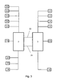
- Fig. 3 shows some exemplary outputs and inputs of the PLC 2 and the PLC 3 and the signals applied to these inputs and processed by both components.
- electrical components commercially available standard parts can be used.
- the link to the central PLC is described below by way of example.
- a redundant input and output 14 exchanges signals with the tachogenerator 8 and with the Winkel suitsencoder 11 and with a drive shaft of the carrier.
- the input and output with respect to the angle-step coder can also not be designed redundantly.
- the signal from the angle step encoder of each of the two steps is read in via the input and output at the respective PLC.
- the input and output 15 is designed completely redundant. This serves as an interface for signals on the actual value of a driving lever, on the current direction of travel and on the current operating state of an automatic or manual operation.
- the input and output 16 serves to output the incoming signals from a brake system for the purpose of visualization.
- This input and output is not redundant, but only assigned to PLC 2.
- the first PLC 2 and the second PLC 3 each have an input and output 17a and 17b for hardware signals. These are on each in the PLC adapted existing hardware and are used for their programming.
- the redundant input and output 18 is provided for an output relay for blocking a departure, for an emergency stop signal, a signal of a stationary and / or slipping in the direction of the machine and / or for a Aufholsignal.
- the inputs and outputs 19 and 20 serve as interfaces for output signals for a brake setpoint in an automatic mode or for a setpoint of other converter devices.
- the data exchange between the PLC 2 and the PLC 3 takes place as described via a DP / DP coupler.
- This has devices 21 and 22 for a bus separation.
- the trained redundant control unit allows two-channel monitoring, which act in the safety circuit of the conveyor system.
- a synchronization of both control channels is detected and detected errors are detected.
- the first PLC 2 and in the second PLC 3 monitoring functions are implemented in software.
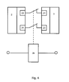
- the basic principle pursued for the synchronization monitoring is in Fig. 4 shown.
- the signals applied to the contactors and generated by one of the PLCs are evaluated by the other PLC for synchronization monitoring.
- the contactors can be connected to other contacts with the safety circuit of the carrier. When a wire breaks, the contactors are disconnected and the now inactive synchronization monitoring triggers in each of the programmable logic controllers 2 and 3 corresponding safety routines.
- the signals monitored for synchronization in both PLCs are composed of control signals from the safety circuits, system parameters calculated in both PLCs, and condition monitors executed by both PLCs.
- the following control signals are expediently monitored for synchronization: control signals from terminating relays, signals from a detection relay via a creeping machine, signals from a relay via a blocked exit, signals from directional relays and signals from system-specific control contactors.
- a synchronous monitoring of the following internal PLC generated or processed signals is executed: a calculated value for the depth, in double-staggered conveyors of each calculated for a first and a second strand depth, monitoring parameters of Winkel suitsencoders, in particular certain predetermined limits, a sum of Teufenhong double-decker conveyor systems, the signals obtained from the tachogenerator, calculated, stored or entered setpoint curves for the control system's release behavior and the values of the continuous monitoring curves for the conveyor's travel speed stored in both PLCs.
- the following monitoring parameters are expediently checked for consistency by both PLCs: a current status of a limit switch for a depth calculation, a match of depth factors, jumps in the calculated depths, a switching behavior of the cutoff switches, in particular their switching outside a window range, and a check of the calculated depths a predefined deviation at each cutoff switch. Furthermore, exceeding of limit values of double or double Conveyors of Winkel Colourencoder executed.
- the above-mentioned monitors are designed to be testable.
- the comparison parameter is a software-type simulation that simulates the effects of each variable test parameter on the condition of the other system parameters. Conveniently, this step sequences are provided so that no additional programming technology must be used. As a result, regular tests are time-efficient and exactly executable. For safety reasons, such a test can only be carried out if a safety brake device is triggered. It is executed via visualization on an external computer system and access to at least one of the two PLCs.
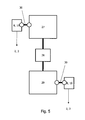
- Fig. 5 shows an exemplary coupling of the tachometer generators 8 and angle step encoder 10 with the drive elements of the carrier.
- the signal generator for the speed and the delivery path are duplicated.
- the signals generated by these duplicate parts are checked for consistency in the PLC.
- a strand determines the entire direction of rotation and conveying of the system. It is true that the executed on a run movement in the conveyor shaft into the conveyor on a direction of travel "hanging" corresponds. Thus, the calculations of depths refer to these definitions.
- a DC motor 27 which is fed by a Leonardumformer not shown here.
- This consists of a starter motor with a starter, in particular a liquid starter, a synchronous motor and a DC generator.
- an excitation current of the DC generator via a DC-DC converter fed. It contains a power converter, a speed controller and a current controller. For this a 4-quadrant operation is used.
- the constant excitation current generated by the synchronous motor is also fed via a DC-DC converter.
- a traction sheave 29 is driven at a substantially constant power. Both the DC motor 27 and the traction sheave ever a toothed belt device 30 is arranged, which transmits the movements of these components to each tachogenerator 8 and an angle step encoder 10 without slip.
- Fig. 6 shows an exemplary shaft switch assembly in a first strand 31 a and a second strand 31 b.
- a shaft switch magnetic switch with mining approval are suitably used. These are preferably mounted in the Ab Kunststoff- and delay range. The required number can be adapted to the actual conveyor system.
- two Abticianschalter are paired for each Trum.
- the corresponding to the respective first Abêtschalter second Ab Kunststoffschalter is mounted in the opposite of the traction sheave 29.
- three pairs Ab Kunststoffschalter 32, 33 and 34 are distributed over both runs.
- Additional switches 35 and 36 are provided in the area of a location referred to herein as "turf bank" or in the region of the filling location on the shaft bottom.
- the paired Ab Kunststoffschalter perform two functions.
- a first function consists in a Abgreskontrolle and a speed monitoring, which is related to the Teufenwert of the respective strand.
- a second function is that these Ab Kunststoffschalter form a benchmark for a Teufenlitis. The defined by this fixed point is formed by the values of the total depth reduced by the depth value of the diversion point.
- the determination of the depth in each run is carried out by the evaluation of the angle step signals from each angle step encoder in conjunction with a depth factor.
- the depth is calculated both in the first PLC 2 and in the second PLC 3 for each run.
- Each angle step encoder is directly coupled to the Profibus of the respective PLC via a controller board for the connection to the Profibus.
- the value of the angle step encoder received in each of the PLCs and the depth value determined thereby are exchanged between the two PLCs via the DP / DP coupling and compared with each other.
- a calibration run of the conveyor is performed. This is expediently at a control panel of the system by means of a key switch triggered to prevent unintentional recalibrations of the system and thus safety risks.
- a preset signal is transmitted to the angle step encoder at the stationary shutdown switch 32 of each dream. This signal is used to synchronize the absolute values of the angle step encoders with the fixed points in the shaft designated by the cutoff switches 32.
- the depth factors are recalculated each time the traction sheave is used and used to determine the depth. With such a method, wear of the traction sheave chuck can be compensated automatically. For further synchronization of the guideway with the Winkel Murphyencodern a preset value in the form of a fixed angular step is transmitted to one or both shaft switches 32 in the Winkelitzencoder.
- Y i a value for the desired speed
- x a depth value
- n an absolute depth value which indicates the depth for the start of the straight line equation
- the slope m i and the offset n i is calculated and a data block, which may be formed as part of the two PLC, stored.
- the calculations of the diversion curves are done in both PLCs. They are monitored for equality. In a design with the lowest possible cycle time within the PLC, a sufficiently long reaction time is obtained for plant control.
- the calculated speed setpoint is normalized and transferred to a drive controller in the form of a control signal.
- a drive controller in the form of a control signal.
- This is in particular the already mentioned DC chopper of Leonardumformers the prime mover.
- the control signal is also compatible with other types of drive controllers, such as direct-current DC motors, frequency converters, or other similar devices.
- the "drive on”, “drive direction” and “speed setpoint” signals are transferred to the drive controller. This signal is served by a conveyor operator Manual setpoint generator linked, whereby at any time an actual speed of the drive can be changed continuously.
- the manual setpoint generator is a combination of a setpoint potentiometer and an electronic converter. This converts variable current values into speed values. The setpoint given in this way is compared with the travel curve. If the setpoint of the manual setpoint generator is above the calculated setpoint of the travel curve, the setpoint value is taken from the calculated travel curve that is used to control the drive controller. Thus, a full display of the manual setpoint encoder also causes the carrier to automatically stop.
- the travel curve can be influenced in its Ab Kunststoffbeginninn, the deceleration and the acceleration in a visualization system, which is connected via appropriate interfaces with the two PLCs.
- a visualization system which is connected via appropriate interfaces with the two PLCs.
- PC systems on which a visualization software is implemented for example, recourse is made to PC systems on which a visualization software is implemented.
- the connection of the PC system with the PLC takes place, for example, via an MPI bus.
- the PC system is expediently designed to be redundant. If one PC fails, the visualization can be called up on the other PC.
- FIG Fig. 7 An exemplary representation of a display of the travel curve parameters is shown in FIG Fig. 7 shown.
- the figure shows an input window 40 for setting parameters for the mentioned travel curve.
- the input window contains input fields 41 for specifying a curve slope in the form of a Ab Griffinoffset, a maximum speed, a minimum speed for speed monitoring, a revision speed, an overspeed and a crawl speed.
- input fields 42 it is possible to enter a value for each of the mentioned parameters, to track an actual value and to specify a setpoint value.
- Input fields 43 allow depths, target and overspeeds for one run pretend.
- a button 44 allows a calculation of the driving curves, a diagram 45 shows the course of the parameter graphically.
- the continuous monitoring curve is calculated by scaling up with a safety factor.
- the speed provided by the tachogenerators is compared dynamically with this monitoring curve.
- a safety brake is triggered as soon as the tacho value exceeds the calculated limit value.
- the calculated diversion curve is monitored for a run down.
- a dynamic comparison of the value of the pay-off cam with the actual speed ensures that the speed follows the calculated target value. This monitoring is required especially in automatic operation. It can be provided in manual mode.
- two parameters are set for continuous speed monitoring. On the one hand, this is a percentage overspeed on the basis of a maximum speed of the carrier. On the other hand, a minimum speed is set, in which an overspeed is displayed.
- Fig. 8 shows an exemplary representation of a display for the definition of sole areas, Teufen Attachern and Teufenlomi.
- the sole areas can be defined with an input window 46 and tracked in their setpoint and actual values. In particular, it is possible to specify this information by means of input fields 47 to 50 for each strand individually, for filling locations and different sole areas.
- a determination of limit switches for depth indicator is possible with input fields 51.
- Parameters for the depth calculation, in particular multiplication factors and offset values and encoder positions for both dreams, can be defined and tracked with input fields 52.
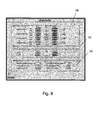
- Fig. 9 shows a visualization of the conveyor system, with the positions of the conveyor baskets and the conveying speeds can be detected in a simple manner.
- the visualization shows a schematic representation 53 of the first and second run with an indicated tower structure.
- the positions of the respective cars are represented by indicators 54a and 54b.
- Trumdarwolf 53 On a scale on Trumdar ein 53, the positions of the cars, especially their Teufe be read.
- Trumdar ein 53 In addition to the Trumdar ein 53 are section representations 55 and 56, in which the positions of the cars is displayed for each strand with a higher resolution. In conjunction with this, the current positions of the conveyor baskets are indicated by numbers in display boxes 57 and 58 for each run. Furthermore, an indication of the actual and the target speed.
- shown visualization can contain more, not shown here display fields. For example, indications of malfunctions, self-drives, telemetric status data at selected locations of the drive and the like further information can be displayed.
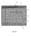
- FIG. 5 shows an exemplary speed controller protocol 59.
- the abscissa 60 of the diagram contains time information, showing the time lapses of the maximum speed monitoring curve 61, a target speed curve 62 underneath, and a measured actual speed 63 slightly fluctuating around the desired speed curve ,
- a curve 64 shows the time dependence of the measured depth value.
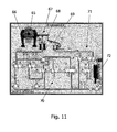
- Fig. 11 shows a visualization of the brake apparatus, in which the states of the components arranged in the brake circuit components are displayed schematically.
- the visualization shows a schematic representation 65 of the traction sheave with a brake shoe symbol 66 and a visualization of the brake mechanism 67.
- the state of the main brake mechanism is indicated in a symbolic representation 68 and the state of a mass brake serving as a safety system is displayed in a further illustration 69.
- the visualization includes a representation 70 of the brake lines and valves of the main brake device and a representation 71 of the valves for triggering the mass brake.
- a compressor system for generating the brake pressure is visualized in a representation 72.
- the states of the brake system shown in the visualization serve signals that are transmitted from the participating components via the Profibus couplings to the first and second PLC and transmitted from there to the computer system for further processing.
- Fig. 12 shows a visualization 73 of the already described components of the carrier.
- the visualization includes a representation 74 of the Leonard set and a representation 75 of the drive components.
- the visualization of Leonardsatzes contains in particular a representation 76 of a thermostat with a display of the current temperature, a representation 77 of the synchronous motor with display fields for temperature and operating condition, a representation 78 of the DC generator with a temperature display and a display 79 of a Throw-off engine.
- the visualization of the Leonard set contains, among other things, a visualization 80 of a lubrication circuit of the Leonard set with a representation of an oil pump arrangement, an oil tank with an attached thermostatic device and an indication of the oil pressure at various bearings within the Leonardumformers.
- the operating status of the named components is visualized by display fields and signal points.
- visualizations 81 and 82 of an air filter unit and a starter connected to the Leonard set are provided. The latter contains, among other things, signal indicators about its extension status and its operating temperature.
- the representation 75 includes a visualization 83 of the conveyor motor, a visualization 84 of the transmission and a visualization 85 of the traction sheave. Display panels for reading a current operating temperature are arranged on some of these visualizations. Furthermore, each one visualization 86 is provided for displaying the tachogenerators and Winkel suitsencoder.
- the temperature indicator for the conveyor motor shows the effectiveness of an air filter unit represented by means of a visualization 87.
- a visualization 88 is provided. This includes in particular visualized repair switches for drives, compressors and starters, switches for extending and retracting the starter or switches for starting or stopping oil pumps for the lubricating oil circuit or the fan in the area of the Leonard converter and / or the conveyor motor.
Landscapes
- Physics & Mathematics (AREA)
- General Physics & Mathematics (AREA)
- Engineering & Computer Science (AREA)
- Automation & Control Theory (AREA)
- Control Of Conveyors (AREA)
- Control Of Electric Motors In General (AREA)
Applications Claiming Priority (1)
| Application Number | Priority Date | Filing Date | Title |
|---|---|---|---|
| DE200910058571 DE102009058571A1 (de) | 2009-12-17 | 2009-12-17 | Vorrichtung zur Fahrtregelung für eine ein- oder doppeltrümige Förderanlage und Verfahren zum Ausführen der Fahrtregelung |
Publications (1)
| Publication Number | Publication Date |
|---|---|
| EP2367085A1 true EP2367085A1 (fr) | 2011-09-21 |
Family
ID=44303329
Family Applications (1)
| Application Number | Title | Priority Date | Filing Date |
|---|---|---|---|
| EP10075751A Withdrawn EP2367085A1 (fr) | 2009-12-17 | 2010-12-09 | Dispositif de réglage de la marche pour une installation de transport à un ou deux tours et procédé de réalisation du réglage de la marche |
Country Status (3)
| Country | Link |
|---|---|
| EP (1) | EP2367085A1 (fr) |
| DE (1) | DE102009058571A1 (fr) |
| RU (1) | RU2010150926A (fr) |
Cited By (2)
| Publication number | Priority date | Publication date | Assignee | Title |
|---|---|---|---|---|
| CN113003327A (zh) * | 2021-03-31 | 2021-06-22 | 广西建工集团建筑机械制造有限责任公司 | 一种基于plc控制的高速施工升降机电控系统及其控制方法 |
| CN114637259A (zh) * | 2020-12-16 | 2022-06-17 | 现代自动车株式会社 | 操作自动引导车辆和自主移动机器人的系统和方法 |
Families Citing this family (2)
| Publication number | Priority date | Publication date | Assignee | Title |
|---|---|---|---|---|
| CN111847185B (zh) * | 2020-07-30 | 2021-12-14 | 中建四局华南建设有限公司 | 一种施工电梯防坠装置 |
| CN121672298B (zh) * | 2026-02-09 | 2026-04-28 | 洛阳理工学院 | 一种电梯安全双重预防机制运行效果评价方法 |
Citations (4)
| Publication number | Priority date | Publication date | Assignee | Title |
|---|---|---|---|---|
| DE10146044A1 (de) * | 2001-09-18 | 2003-04-03 | Militzer Otto Michael | Verfahren und Vorrichtung zur Kontrolle der Bewegungsabläufe bei Anlagen zur Personenbeförderung |
| EP1787937A2 (fr) * | 2003-10-16 | 2007-05-23 | Luis Rodolfo Zamorano Morf N | Amelioration apportee a un ascenseur de passagers ou de charge base sur l'utilisation de chaines, contrepoids et servomoteurs |
| EP1864935A1 (fr) * | 2005-03-31 | 2007-12-12 | Mitsubishi Denki Kabushiki Kaisha | Appareil d'ascenseur |
| EP2022742A1 (fr) * | 2007-08-07 | 2009-02-11 | ThyssenKrupp Elevator AG | Système d'ascenseur |
Family Cites Families (2)
| Publication number | Priority date | Publication date | Assignee | Title |
|---|---|---|---|---|
| DE10025085A1 (de) * | 2000-05-20 | 2001-12-06 | Peter Wratil | Modul zur Steuerung oder Regelung von sicherheitsrelevanten Vorgängen oder Abläufen für den Betrieb von Maschinen oder Anlagen |
| DE102004058756A1 (de) * | 2004-12-06 | 2006-06-14 | Siemens Ag | Geschwindigkeitsüberwachungsverfahren in einem Automatisierungssystem für eine Förderanlage |
-
2009
- 2009-12-17 DE DE200910058571 patent/DE102009058571A1/de not_active Withdrawn
-
2010
- 2010-12-09 EP EP10075751A patent/EP2367085A1/fr not_active Withdrawn
- 2010-12-13 RU RU2010150926/11A patent/RU2010150926A/ru not_active Application Discontinuation
Patent Citations (4)
| Publication number | Priority date | Publication date | Assignee | Title |
|---|---|---|---|---|
| DE10146044A1 (de) * | 2001-09-18 | 2003-04-03 | Militzer Otto Michael | Verfahren und Vorrichtung zur Kontrolle der Bewegungsabläufe bei Anlagen zur Personenbeförderung |
| EP1787937A2 (fr) * | 2003-10-16 | 2007-05-23 | Luis Rodolfo Zamorano Morf N | Amelioration apportee a un ascenseur de passagers ou de charge base sur l'utilisation de chaines, contrepoids et servomoteurs |
| EP1864935A1 (fr) * | 2005-03-31 | 2007-12-12 | Mitsubishi Denki Kabushiki Kaisha | Appareil d'ascenseur |
| EP2022742A1 (fr) * | 2007-08-07 | 2009-02-11 | ThyssenKrupp Elevator AG | Système d'ascenseur |
Cited By (3)
| Publication number | Priority date | Publication date | Assignee | Title |
|---|---|---|---|---|
| CN114637259A (zh) * | 2020-12-16 | 2022-06-17 | 现代自动车株式会社 | 操作自动引导车辆和自主移动机器人的系统和方法 |
| CN114637259B (zh) * | 2020-12-16 | 2026-06-30 | 现代自动车株式会社 | 操作自动引导车辆和自主移动机器人的系统和方法 |
| CN113003327A (zh) * | 2021-03-31 | 2021-06-22 | 广西建工集团建筑机械制造有限责任公司 | 一种基于plc控制的高速施工升降机电控系统及其控制方法 |
Also Published As
| Publication number | Publication date |
|---|---|
| RU2010150926A (ru) | 2012-06-20 |
| DE102009058571A1 (de) | 2011-06-22 |
Similar Documents
| Publication | Publication Date | Title |
|---|---|---|
| DE69517546T2 (de) | Einrichtung und Verfahren zum Aufzugstürensteuerung | |
| EP2460056B1 (fr) | Procédé et dispositif de surveillance de l'absence d'erreur d'une grandeur de déplacement sur un mécanisme d'entraînement électrique | |
| EP3704048B1 (fr) | Dispositif de surveillance de sécurité destiné à surveiller des conditions relatives à la sécurité dans une installation de transport de personnes ainsi que procédé de fonctionnement d'un tel dispositif | |
| DE102009044848A1 (de) | Verfahren und Vorrichtung zum Bestätigen der Ausgabe von einem Sensor | |
| EP2457860A2 (fr) | Dispositif de sécurité pour ascenseur | |
| DE102019122703A1 (de) | Steuereinheit und Verfahren zum Betrieb eines Fördermittels | |
| DE102009058571A1 (de) | Vorrichtung zur Fahrtregelung für eine ein- oder doppeltrümige Förderanlage und Verfahren zum Ausführen der Fahrtregelung | |
| DE102018003397A1 (de) | Anomaliediagnosevorrichtung und Anomaliediagnoseverfahren | |
| DE102006034962A1 (de) | Verfahren zum gesicherten Bremsen eines Hubwerkes sowie Vorrichtung zur Durchführung des Verfahrens | |
| DE102014106166B4 (de) | Vorrichtung und Verfahren zum fehlersicheren Überwachen eines beweglichen Maschinenteils | |
| DE4234501A1 (de) | Steuerungsverfahren zur Begrenzung der Antriebskraft eines Antriebs, insbesondere eines Tür- oder Drehflügelantriebs sowie zugehörige Sicherheitsschaltung | |
| EP2177439B1 (fr) | Unité de fabrication et procédé de fonctionnement de l'unité de fabrication | |
| DE102018214693A1 (de) | Verfahren zum Überwachen eines elektrischen Motors, elektronisches Steuerungsmodul, hydraulisches Bremssystem und Speichermedium | |
| WO2020229119A1 (fr) | Ensemble commutateur comprenant un système d'entraînement | |
| EP3848314A1 (fr) | Système de mesure de la charge dans un système d'ascenseur ainsi que procédé de détermination de la charge d'une cabine d'ascenseur | |
| DE102009044849A1 (de) | Verfahren und Vorrichtung zum Regeln von automatischen Starts und Stopps des Motors eines Fahrzeugs | |
| EP3120203B1 (fr) | Dispositif et procédé servant à identifier des anomalies dans des machines | |
| DE102009008132B4 (de) | Torsteuerung zur Steuerung eines elektromotorisch angetriebenen Tores | |
| DE102019112715B3 (de) | Verfahren zum Durchführen einer Umschaltung eines Laststufenschalters mittels eines Antriebssystems und Antriebssystem für einen Laststufenschalter | |
| EP2126536B1 (fr) | Dispositif et procédé pour un test de fonctionnement d'un frein | |
| DE102005020170B4 (de) | Hobeleinrichtung und Verfahren zum Ansteuern einer Hobeleinrichtung | |
| DE3203820C2 (fr) | ||
| DE2750584C2 (de) | Schrämmaschine mit Wechselgetriebe zum Antrieb der Schrämwalze o.dgl. | |
| DE102020133239B4 (de) | Vorrichtung zur überwachung einer parkfreigabe für ein fahrzeug mit automatikgetriebe | |
| EP3740828B1 (fr) | Procédé de vérification de la précision d'une valeur de signal d'un capteur sans erreur |
Legal Events
| Date | Code | Title | Description |
|---|---|---|---|
| PUAI | Public reference made under article 153(3) epc to a published international application that has entered the european phase |
Free format text: ORIGINAL CODE: 0009012 |
|
| AK | Designated contracting states |
Kind code of ref document: A1 Designated state(s): AL AT BE BG CH CY CZ DE DK EE ES FI FR GB GR HR HU IE IS IT LI LT LU LV MC MK MT NL NO PL PT RO RS SE SI SK SM TR |
|
| AX | Request for extension of the european patent |
Extension state: BA ME |
|
| STAA | Information on the status of an ep patent application or granted ep patent |
Free format text: STATUS: THE APPLICATION IS DEEMED TO BE WITHDRAWN |
|
| 18D | Application deemed to be withdrawn |
Effective date: 20120322 |