EP2367249A2 - Dispositif de sécurisation contre le déplacement d'un boîtier encastré pour appareils ou tout autre dispositif d'installation électrique sur un canal de guidage de conduite - Google Patents
Dispositif de sécurisation contre le déplacement d'un boîtier encastré pour appareils ou tout autre dispositif d'installation électrique sur un canal de guidage de conduite Download PDFInfo
- Publication number
- EP2367249A2 EP2367249A2 EP11001817A EP11001817A EP2367249A2 EP 2367249 A2 EP2367249 A2 EP 2367249A2 EP 11001817 A EP11001817 A EP 11001817A EP 11001817 A EP11001817 A EP 11001817A EP 2367249 A2 EP2367249 A2 EP 2367249A2
- Authority
- EP
- European Patent Office
- Prior art keywords
- clamping element
- frame
- clamping
- holding
- holding frame
- Prior art date
- Legal status (The legal status is an assumption and is not a legal conclusion. Google has not performed a legal analysis and makes no representation as to the accuracy of the status listed.)
- Granted
Links
Images


Classifications
-
- H—ELECTRICITY
- H02—GENERATION; CONVERSION OR DISTRIBUTION OF ELECTRIC POWER
- H02G—INSTALLATION OF ELECTRIC CABLES OR LINES, OR OF COMBINED OPTICAL AND ELECTRIC CABLES OR LINES
- H02G3/00—Installations of electric cables or lines or protective tubing therefor in or on buildings, equivalent structures or vehicles
- H02G3/02—Details
- H02G3/08—Distribution boxes; Connection or junction boxes
- H02G3/12—Distribution boxes; Connection or junction boxes for flush mounting
- H02G3/128—Distribution boxes; Connection or junction boxes for flush mounting in plinths, channels, raceways or similar
Definitions
- the present invention relates to a device for securing against displacement of a device installation box or other electrical installation device to a cable trunking.
- Device installation boxes of the type mentioned above are from the EP 1 119 087 B1 known, comparable installation boxes also from the EP 07 33 276 B1 , of the DE 93 05 750 U1 or the DE 297 22 471 U 1 ,
- the in the EP 07 33 276 B1 described device installation box attempts to facilitate the work of the electrician by the fact that parts of the bottom, side wall and end wall of the device installation box is designed as a fold-down unit.
- This device mounting box provides during assembly free movement of the line to be assembled, especially during the fixation of the contacted electrical device in the device installation box.
- the unfolded bottom part is pivoted to its final position and locked, at the same time the strain relief for the lines is made.
- the device mounting box is inserted into the cover holding profiles of the channel and fixed immovably by means of screws.
- this type of mounting is still somewhat cumbersome because the installer can not fix the mounting hardware, such as the electrical wiring, the installation device, the bottom part of the box and the top of the can, during the assembly work on the channel.
- the holding devices for the front-locking attachment of the device mounting box are integrally formed on the lower part, so that the Installer attach the first empty can bottom to the trunking channel and then attach the different items to it.
- the hook-shaped holding devices allow a frontrastende attachment of the lower part of the can to the corresponding holding profiles of a cable trunking.
- a socket box in which the attachment is effected in that the socket box in the receiving part has an upper fastening device with a clamping element and a lower fastening device.
- a latching recess is provided, in which corresponding latching projections of the clamping element lead to a latching.
- the latched in the locking recess clamping element presses on the edge of the recess, so that the mounting box is clamped by means of the latched clamping element on the edge of the recess.
- the present invention seeks to improve the known devices for anti-displacement device mounting boxes and other electrical installation equipment on a cable duct, thereby enabling a simplified assembly and disassembly option.
- the displacement protection according to the invention is based on a separate clamping element, which is slidably integrated in an installation component and causes jamming of the holding frame with the channel lower part.
- the device insert with the holding frame locked without screwing. An assembly but also possible disassembly of the entire device complex is thereby fast and efficient.
- the device according to the invention consists of a conventional support frame which defines a central opening for use with a device installation box or other electrical installation means (such as switches). On the support frame per se known locking or clamping elements are mounted, which are used to attach the device to the device mounting box or other electrical installation device.
- the device according to the invention is characterized in that in at least one frame element, a separate clamping element is slidably inserted, which consists of a base body with a protruding over the frame surface slide, wherein in the slide at least one lateral recess for receiving a hand tool and on the body at least one lateral jaw is formed, wherein the clamping element is inserted into the frame member such that it is displaceable along a guide formed on the inside of the frame member from a mounting position to a locking position, wherein formed on the base body (s) jaw ( n) in the mounting position or in the delivery condition rest on the support frame and the clamping element in the locking position an inner strip of the holding frame with one or more clamping lug (s) against the mold holding profiles of a channel lower part for producing a friction seal drüc kt.
- the inner bar is thus part of the lateral frame element.
- the clamping element causes when depressing the slider, that ultimately pressed the inner bar with the clamping lugs formed thereon inwardly against the mold holding profiles of the trunking base and the device insert is held thereby.
- the inner strip is preferably elastic.
- the clamping pressure can be done in different ways depending on the embodiment.
- the clamping pressure is achieved via lateral projecting support surfaces.
- the formed on the body side (s) cheek (s) then serve only to rest and hold the clamping element on the frame for the delivery condition.
- the clamping pressure can also be done directly on the side jaws, with which the inner bar is pressed with the clamping lugs formed thereon inwardly against the mold holding profiles of the trunking base.
- the separate clamping element is guided in the frame member via a slot.
- To guide is located on the outside of the side surfaces of the body a groove which cooperates with the formed on the inside of the frame member guide.
- the guide is a simple rail or groove, which may be formed either on the clamping element itself or alternatively on the frame.
- latching hooks on the clamping element to prevent accidental release or falling out of the clamping element from the guide.
- the latching hooks of the clamping element catch on depression of the slide with a part of the frame element.
- the jaws required for the contact of the clamping element are formed on side surfaces of the base body, wherein the side surfaces are offset relative to the end regions of the clamping element in order to ensure optimum guidance of the clamping element.
- the shape-retaining profiles are preferably cover-holding profiles of a trunking lower part, which are usually used for fastening a device installation box or an electrical installation device.
- the anti-displacement device according to the invention on the device installation box or electrical installation device.
- the jaws are in this position on the frame element.
- the assembly state is also the delivery state. In this position, the entire assembly is displaceable along the trunking channel and can be brought by the installer in the desired position.
- the locking of the device to the channel is carried out by pressing down the slider on the clamping element at the holding frame.
- the lateral jaws slide over a small projection or resistance on the frame element and are pressed into the slot formed therein.
- the depression of the clamping elements is achieved in that the final panel is simply pressed from above after use of the electrical installation device in the device mounting box.
- the assembly is therefore feasible without tools. Since a channel bottom is typically symmetrical, i. has left and right side mold holding profiles, two clamping elements are preferably arranged in the holding frame opposite.
- the clamping element or the clamping elements is simply pulled upwards. In this way, the entire assembly can be quickly removed from the wiring channel and possibly new lines are used. This can be done either by hand or with a hand tool (e.g., screwdriver) for which the lateral recesses on the slider are intended.
- a hand tool e.g., screwdriver
- the recesses allow the insertion of the assembly tool for pushing up the clamping element.
- the frame additionally oppositely arranged resilient retaining lugs and clamping feet are arranged on the frame.
- the clamp feet form a slot.
- the Elektroninstallations réelle is guided from one side into the slot of the clamping feet and fixed when moving through the bottom engaging tabs in the frame.
- the advantage is the fact that the complete assembly can be done completely free of mounting means such as screws or tools. In just a few steps, the fitter can attach, position and finally fix both the device mounting box and the device insert to the cable duct.
- the device according to the invention is suitable for any type of electrical installation device, which is integrated or installed in an installation channel.
- This is preferably a device installation box, in particular a front-locking device installation box.
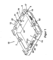
- a holding frame 10 is shown with a central recess for a device insert.
- the holding frame is constructed symmetrically and consists of individual peripheral frame members 12. Furthermore, locking and clamping elements 42 are provided for the attachment of the holding frame 10 to a device mounting box (eg insulating box).
- the outer web 17 defines with the holding frame 10 a gap 18 in which the mold holding profile 52 of the trunking base 50 is guided during assembly.
- the clamping element In the frontal frame members 12, two opposing clamping elements 20 are slidably inserted into the frame member 12 via a slot 14.
- the clamping element according to the invention consists of a base body 23 and a slider 21 formed on the head side, which protrudes beyond the frame surface of the frame element 12 in the mounting position.
- a lateral recess 22 is incorporated, which serves to receive a mounting tool.
- the recess 22 can also be used as a gripping profile for disassembly by hand.
- the clamping element 20 can thereby be pushed from top to bottom.
- jaws 28 are further formed, which prevent the delivery condition that the clamping element falls into the slot 14 and in a preferred embodiment, even a frictional engagement between the support frame 10 and the shape-retaining profile 52 of the channel base 50 can cause.
- the Clamping element 20 over the slider 21 simply pushed up, the friction lock is released and the unit released for repositioning or disassembly.
- two clamping feet 5 can be seen on the holding frame 10, which are arranged opposite one another on the frame elements 12.
- the electrical installation apparatus e.g., switch
- the electrical installation apparatus is first inserted into the slot 6 of the clamping feet 5 and then laterally displaced, whereby the retaining tabs 3 are pressed down.
- the electrical installation apparatus e.g., switch
- the electrical installation apparatus is first inserted into the slot 6 of the clamping feet 5 and then laterally displaced, whereby the retaining tabs 3 are pressed down.
- the electrical installation apparatus e.g., switch
- Fig. 2 a detailed representation of the clamping element 20 according to the invention is shown.
- this consists of a base body 23 and the already mentioned slide 21, in which a lateral recess 22 for releasing the clamping element 20 with a tool (eg screwdriver) is incorporated.
- the jaws 28 are located on the side inner surfaces 27 of the base body 23 and are in the delivery state on the support frame 10, thereby preventing the collapse of the clamping element 20.
- a groove 26 is incorporated.
- the side surface 27 is offset from the support surfaces 25.1, 25.2 inwards. In this way, a stepless guidance of the clamping element 20 is ensured in the support frame 10.
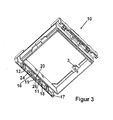
- Fig. 3 the already mentioned holding frame 10 is shown from the bottom.
- the shape-retaining profiles 52 of a channel lower part 50 are guided in the recess 18 and held by holding devices 17.
- the clamping element 20 is pressed down, whereby the clamping lugs 11, which are formed on the inner strip 16 of the web 17, are pressed against the shape retaining profiles 52 of the channel base 50 and enter into a friction lock.
- the displaceability of the clamping element 20 is ensured by a formed on the inside of the frame member 12 guide 19, shown here as a rail, and a matching groove 26 on the clamping element 20.
- the locking hooks 24 engage with the device installation box.
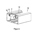
- Fig. 4 the locking state of the device according to the invention is shown.
- the holding frame 10 is inserted into the corresponding shape holding profiles 52 of a channel lower part 50.
- the holding frame 10 along the mold holding profiles 52 can be moved laterally.
- To lock the clamping member 20 is pressed down so that, depending on the embodiment, either the support surfaces 25.1, 25.2 or the jaws 28 are pressed against the inner sides of the support frame 10.
- the clamping lugs 11 ultimately cause a frictional engagement with the shape-retaining profile 52 of the channel base 50, whereby the holding frame 10 is fixed.
- Fig. 5 the individual elements and the function of the device according to the invention are shown in a sectional view.
- the web 17 In the right half of the figure can be seen the web 17 and the inserted in the slot 14 clamping member 20.
- the jaws 28 slide over a small projection 29 on the frame member 12.
- either the support surfaces 25.1, 25.2 or the jaws 28 press the clamping lugs 11 of the inner bar 16 inwardly against the shape retaining profiles 52 of the channel base 50 and cause the Friction.
- the holding frame 10 is placed on an insulating box. About lateral locking and clamping elements 42 of the holding frame 10 is locked with the insulating box.
- the entire assembly can be moved along the cable trunking.
- the slider 21 of the clamping element 20 is pressed down.
- the slider 21 is pushed upwards, whereby the frictional engagement of the support surfaces 25.1, 25.2, or, depending on the embodiment, the jaws 28 is released.
Landscapes
- Engineering & Computer Science (AREA)
- Architecture (AREA)
- Civil Engineering (AREA)
- Structural Engineering (AREA)
- Connection Or Junction Boxes (AREA)
- Casings For Electric Apparatus (AREA)
- Installation Of Indoor Wiring (AREA)
- Insertion, Bundling And Securing Of Wires For Electric Apparatuses (AREA)
Applications Claiming Priority (1)
| Application Number | Priority Date | Filing Date | Title |
|---|---|---|---|
| DE201010011855 DE102010011855B4 (de) | 2010-03-18 | 2010-03-18 | Vorrichtung zur Verschiebesicherung einer Geräteeinbaudose oder sonstigen Elektroinstallationseinrichtungen an einem Leitungsführungskanal |
Publications (3)
| Publication Number | Publication Date |
|---|---|
| EP2367249A2 true EP2367249A2 (fr) | 2011-09-21 |
| EP2367249A3 EP2367249A3 (fr) | 2012-07-25 |
| EP2367249B1 EP2367249B1 (fr) | 2013-11-20 |
Family
ID=44070707
Family Applications (1)
| Application Number | Title | Priority Date | Filing Date |
|---|---|---|---|
| EP11001817.3A Active EP2367249B1 (fr) | 2010-03-18 | 2011-03-04 | Dispositif de sécurisation contre le déplacement d'un boîtier encastré pour appareils ou tout autre dispositif d'installation électrique sur un canal de guidage de conduite |
Country Status (3)
| Country | Link |
|---|---|
| EP (1) | EP2367249B1 (fr) |
| DE (1) | DE102010011855B4 (fr) |
| DK (1) | DK2367249T3 (fr) |
Citations (5)
| Publication number | Priority date | Publication date | Assignee | Title |
|---|---|---|---|---|
| DE9305750U1 (de) | 1993-04-16 | 1993-06-17 | OBO Bettermann oHG, 5750 Menden | Gerätedose für elektrische Installationen |
| DE29722471U1 (de) | 1997-12-19 | 1998-02-12 | Albert Ackermann GmbH & Co. KG, 51643 Gummersbach | Einbaudose zum Einsetzen in einen Installationskanal |
| EP0733276B1 (fr) | 1994-10-11 | 1999-04-28 | Albert Ackermann GmbH & Co. KG | Boite de connexion d'appareils pour montage affleure dans des conduits d'installation |
| EP1119087B1 (fr) | 2000-01-18 | 2003-03-12 | Tehalit GmbH & Co. KG | Boíte d'encastrement pour canalisations de câbles |
| DE10232102B4 (de) | 2002-07-15 | 2004-07-08 | Günther Spelsberg GmbH & Co. KG | Einbaudose |
Family Cites Families (1)
| Publication number | Priority date | Publication date | Assignee | Title |
|---|---|---|---|---|
| DE10054662C2 (de) * | 2000-11-03 | 2003-07-17 | Spelsberg Guenther Gmbh Co Kg | Einbaudose für die werkzeugfreie Montage |
-
2010
- 2010-03-18 DE DE201010011855 patent/DE102010011855B4/de not_active Expired - Fee Related
-
2011
- 2011-03-04 DK DK11001817T patent/DK2367249T3/da active
- 2011-03-04 EP EP11001817.3A patent/EP2367249B1/fr active Active
Patent Citations (5)
| Publication number | Priority date | Publication date | Assignee | Title |
|---|---|---|---|---|
| DE9305750U1 (de) | 1993-04-16 | 1993-06-17 | OBO Bettermann oHG, 5750 Menden | Gerätedose für elektrische Installationen |
| EP0733276B1 (fr) | 1994-10-11 | 1999-04-28 | Albert Ackermann GmbH & Co. KG | Boite de connexion d'appareils pour montage affleure dans des conduits d'installation |
| DE29722471U1 (de) | 1997-12-19 | 1998-02-12 | Albert Ackermann GmbH & Co. KG, 51643 Gummersbach | Einbaudose zum Einsetzen in einen Installationskanal |
| EP1119087B1 (fr) | 2000-01-18 | 2003-03-12 | Tehalit GmbH & Co. KG | Boíte d'encastrement pour canalisations de câbles |
| DE10232102B4 (de) | 2002-07-15 | 2004-07-08 | Günther Spelsberg GmbH & Co. KG | Einbaudose |
Also Published As
| Publication number | Publication date |
|---|---|
| EP2367249A3 (fr) | 2012-07-25 |
| DE102010011855A1 (de) | 2011-09-22 |
| DE102010011855B4 (de) | 2011-09-29 |
| DK2367249T3 (da) | 2014-02-10 |
| EP2367249B1 (fr) | 2013-11-20 |
Similar Documents
| Publication | Publication Date | Title |
|---|---|---|
| DE202017102147U1 (de) | Leitungsdurchführung, insbesondere Zugentlastung für eine Energieführungskette | |
| EP3639334A1 (fr) | Fixation de rail de support | |
| EP2083490B1 (fr) | Boîte de jonction pour sol pour installations électriques | |
| DE3112347C2 (de) | Einbaudose für elektrische Installationsgeräte | |
| DE102011010828B4 (de) | Klemmvorrichtung zur lösbaren Befestigung eines Gerätegehäuses an einer Profilschiene | |
| EP2273640B1 (fr) | Support d'outils pour canaux de plinthes à socles | |
| DE102005022441B4 (de) | Kanal-Steckdose | |
| EP2367249B1 (fr) | Dispositif de sécurisation contre le déplacement d'un boîtier encastré pour appareils ou tout autre dispositif d'installation électrique sur un canal de guidage de conduite | |
| EP2965656B1 (fr) | Dispositif de montage pour un élément support sur une colonne porteuse | |
| DE112015004838B4 (de) | Temporäre platzierungsstruktur für eine unterabdeckung | |
| EP2639911B1 (fr) | Elément de montage pour canaux d'intégration d'appareils, canal d'intégration d'appareils doté d'un tel élément de montage et procédé de montage d'un tel élément de montage dans un canal d'intégration d'appareils | |
| DE202007016981U1 (de) | Befestigungsvorrichtung für ein elektrotechnisches Bauteil | |
| DE102010033648B4 (de) | Anordnung aus einem Behältnis zur Aufnahme von elektrischen Steckdosenleisten und einem Deckel | |
| EP2538510B1 (fr) | Panier d'appareillage pour installations électriques souterraines | |
| EP2461444B1 (fr) | Boîtier d'appareil encastrable pivotant pour un caniveau pour câbles | |
| DE202014100332U1 (de) | Vorrichtung zur lösbaren Befestigung von Funktionsteilen | |
| DE10232102B4 (de) | Einbaudose | |
| EP2590282B1 (fr) | Dispositif pour le montage d'appareils dans des installations électriques avec sécurisation de capot | |
| DE102010012075B3 (de) | Geräteeinbaudose für Leitungsführungskanäle oder Installationskanäle | |
| DE10135662A1 (de) | Gerätebecherrahmen für Unterfluranwendungen | |
| EP2690729A1 (fr) | Système d'installation électrique et boîtier pour cloison creuse pour l'installation électrique | |
| WO2012139697A1 (fr) | Système de fermeture de porte | |
| AT403637B (de) | Elektrisches installationsgerät | |
| EP2597742A2 (fr) | Porte-outils pour le montage d'un appareil dýinstallation électrique sur un canal de guidage de conduite | |
| DE69826100T2 (de) | Haltevorrichtung für elektrische vorrichtung |
Legal Events
| Date | Code | Title | Description |
|---|---|---|---|
| PUAI | Public reference made under article 153(3) epc to a published international application that has entered the european phase |
Free format text: ORIGINAL CODE: 0009012 |
|
| AK | Designated contracting states |
Kind code of ref document: A2 Designated state(s): AL AT BE BG CH CY CZ DE DK EE ES FI FR GB GR HR HU IE IS IT LI LT LU LV MC MK MT NL NO PL PT RO RS SE SI SK SM TR |
|
| AX | Request for extension of the european patent |
Extension state: BA ME |
|
| PUAL | Search report despatched |
Free format text: ORIGINAL CODE: 0009013 |
|
| AK | Designated contracting states |
Kind code of ref document: A3 Designated state(s): AL AT BE BG CH CY CZ DE DK EE ES FI FR GB GR HR HU IE IS IT LI LT LU LV MC MK MT NL NO PL PT RO RS SE SI SK SM TR |
|
| AX | Request for extension of the european patent |
Extension state: BA ME |
|
| RIC1 | Information provided on ipc code assigned before grant |
Ipc: H02G 3/12 20060101AFI20120619BHEP |
|
| 17P | Request for examination filed |
Effective date: 20121115 |
|
| GRAJ | Information related to disapproval of communication of intention to grant by the applicant or resumption of examination proceedings by the epo deleted |
Free format text: ORIGINAL CODE: EPIDOSDIGR1 |
|
| GRAP | Despatch of communication of intention to grant a patent |
Free format text: ORIGINAL CODE: EPIDOSNIGR1 |
|
| INTG | Intention to grant announced |
Effective date: 20130412 |
|
| INTG | Intention to grant announced |
Effective date: 20130416 |
|
| GRAS | Grant fee paid |
Free format text: ORIGINAL CODE: EPIDOSNIGR3 |
|
| GRAP | Despatch of communication of intention to grant a patent |
Free format text: ORIGINAL CODE: EPIDOSNIGR1 |
|
| GRAA | (expected) grant |
Free format text: ORIGINAL CODE: 0009210 |
|
| INTG | Intention to grant announced |
Effective date: 20130923 |
|
| AK | Designated contracting states |
Kind code of ref document: B1 Designated state(s): AL AT BE BG CH CY CZ DE DK EE ES FI FR GB GR HR HU IE IS IT LI LT LU LV MC MK MT NL NO PL PT RO RS SE SI SK SM TR |
|
| REG | Reference to a national code |
Ref country code: GB Ref legal event code: FG4D Free format text: NOT ENGLISH |
|
| REG | Reference to a national code |
Ref country code: CH Ref legal event code: EP |
|
| REG | Reference to a national code |
Ref country code: AT Ref legal event code: REF Ref document number: 642125 Country of ref document: AT Kind code of ref document: T Effective date: 20131215 |
|
| REG | Reference to a national code |
Ref country code: IE Ref legal event code: FG4D Free format text: LANGUAGE OF EP DOCUMENT: GERMAN |
|
| REG | Reference to a national code |
Ref country code: DE Ref legal event code: R096 Ref document number: 502011001650 Country of ref document: DE Effective date: 20140116 |
|
| REG | Reference to a national code |
Ref country code: DK Ref legal event code: T3 Effective date: 20140206 |
|
| REG | Reference to a national code |
Ref country code: CH Ref legal event code: NV Representative=s name: RENTSCH PARTNER AG, CH |
|
| REG | Reference to a national code |
Ref country code: NL Ref legal event code: T3 |
|
| REG | Reference to a national code |
Ref country code: SE Ref legal event code: TRGR |
|
| REG | Reference to a national code |
Ref country code: LT Ref legal event code: MG4D |
|
| PG25 | Lapsed in a contracting state [announced via postgrant information from national office to epo] |
Ref country code: LT Free format text: LAPSE BECAUSE OF FAILURE TO SUBMIT A TRANSLATION OF THE DESCRIPTION OR TO PAY THE FEE WITHIN THE PRESCRIBED TIME-LIMIT Effective date: 20131120 Ref country code: HR Free format text: LAPSE BECAUSE OF FAILURE TO SUBMIT A TRANSLATION OF THE DESCRIPTION OR TO PAY THE FEE WITHIN THE PRESCRIBED TIME-LIMIT Effective date: 20131120 Ref country code: NO Free format text: LAPSE BECAUSE OF FAILURE TO SUBMIT A TRANSLATION OF THE DESCRIPTION OR TO PAY THE FEE WITHIN THE PRESCRIBED TIME-LIMIT Effective date: 20140220 Ref country code: IS Free format text: LAPSE BECAUSE OF FAILURE TO SUBMIT A TRANSLATION OF THE DESCRIPTION OR TO PAY THE FEE WITHIN THE PRESCRIBED TIME-LIMIT Effective date: 20140320 Ref country code: FI Free format text: LAPSE BECAUSE OF FAILURE TO SUBMIT A TRANSLATION OF THE DESCRIPTION OR TO PAY THE FEE WITHIN THE PRESCRIBED TIME-LIMIT Effective date: 20131120 |
|
| PG25 | Lapsed in a contracting state [announced via postgrant information from national office to epo] |
Ref country code: ES Free format text: LAPSE BECAUSE OF FAILURE TO SUBMIT A TRANSLATION OF THE DESCRIPTION OR TO PAY THE FEE WITHIN THE PRESCRIBED TIME-LIMIT Effective date: 20131120 Ref country code: RS Free format text: LAPSE BECAUSE OF FAILURE TO SUBMIT A TRANSLATION OF THE DESCRIPTION OR TO PAY THE FEE WITHIN THE PRESCRIBED TIME-LIMIT Effective date: 20131120 Ref country code: LV Free format text: LAPSE BECAUSE OF FAILURE TO SUBMIT A TRANSLATION OF THE DESCRIPTION OR TO PAY THE FEE WITHIN THE PRESCRIBED TIME-LIMIT Effective date: 20131120 |
|
| PG25 | Lapsed in a contracting state [announced via postgrant information from national office to epo] |
Ref country code: PT Free format text: LAPSE BECAUSE OF FAILURE TO SUBMIT A TRANSLATION OF THE DESCRIPTION OR TO PAY THE FEE WITHIN THE PRESCRIBED TIME-LIMIT Effective date: 20140320 |
|
| PG25 | Lapsed in a contracting state [announced via postgrant information from national office to epo] |
Ref country code: EE Free format text: LAPSE BECAUSE OF FAILURE TO SUBMIT A TRANSLATION OF THE DESCRIPTION OR TO PAY THE FEE WITHIN THE PRESCRIBED TIME-LIMIT Effective date: 20131120 |
|
| REG | Reference to a national code |
Ref country code: DE Ref legal event code: R097 Ref document number: 502011001650 Country of ref document: DE |
|
| PG25 | Lapsed in a contracting state [announced via postgrant information from national office to epo] |
Ref country code: CZ Free format text: LAPSE BECAUSE OF FAILURE TO SUBMIT A TRANSLATION OF THE DESCRIPTION OR TO PAY THE FEE WITHIN THE PRESCRIBED TIME-LIMIT Effective date: 20131120 Ref country code: PL Free format text: LAPSE BECAUSE OF FAILURE TO SUBMIT A TRANSLATION OF THE DESCRIPTION OR TO PAY THE FEE WITHIN THE PRESCRIBED TIME-LIMIT Effective date: 20131120 Ref country code: RO Free format text: LAPSE BECAUSE OF FAILURE TO SUBMIT A TRANSLATION OF THE DESCRIPTION OR TO PAY THE FEE WITHIN THE PRESCRIBED TIME-LIMIT Effective date: 20131120 Ref country code: SK Free format text: LAPSE BECAUSE OF FAILURE TO SUBMIT A TRANSLATION OF THE DESCRIPTION OR TO PAY THE FEE WITHIN THE PRESCRIBED TIME-LIMIT Effective date: 20131120 |
|
| PLBE | No opposition filed within time limit |
Free format text: ORIGINAL CODE: 0009261 |
|
| STAA | Information on the status of an ep patent application or granted ep patent |
Free format text: STATUS: NO OPPOSITION FILED WITHIN TIME LIMIT |
|
| 26N | No opposition filed |
Effective date: 20140821 |
|
| PG25 | Lapsed in a contracting state [announced via postgrant information from national office to epo] |
Ref country code: LU Free format text: LAPSE BECAUSE OF FAILURE TO SUBMIT A TRANSLATION OF THE DESCRIPTION OR TO PAY THE FEE WITHIN THE PRESCRIBED TIME-LIMIT Effective date: 20140304 |
|
| REG | Reference to a national code |
Ref country code: DE Ref legal event code: R097 Ref document number: 502011001650 Country of ref document: DE Effective date: 20140821 |
|
| REG | Reference to a national code |
Ref country code: IE Ref legal event code: MM4A |
|
| PG25 | Lapsed in a contracting state [announced via postgrant information from national office to epo] |
Ref country code: IE Free format text: LAPSE BECAUSE OF NON-PAYMENT OF DUE FEES Effective date: 20140304 |
|
| PG25 | Lapsed in a contracting state [announced via postgrant information from national office to epo] |
Ref country code: SI Free format text: LAPSE BECAUSE OF FAILURE TO SUBMIT A TRANSLATION OF THE DESCRIPTION OR TO PAY THE FEE WITHIN THE PRESCRIBED TIME-LIMIT Effective date: 20131120 |
|
| PG25 | Lapsed in a contracting state [announced via postgrant information from national office to epo] |
Ref country code: IT Free format text: LAPSE BECAUSE OF FAILURE TO SUBMIT A TRANSLATION OF THE DESCRIPTION OR TO PAY THE FEE WITHIN THE PRESCRIBED TIME-LIMIT Effective date: 20131120 |
|
| GBPC | Gb: european patent ceased through non-payment of renewal fee |
Effective date: 20150304 |
|
| PG25 | Lapsed in a contracting state [announced via postgrant information from national office to epo] |
Ref country code: GB Free format text: LAPSE BECAUSE OF NON-PAYMENT OF DUE FEES Effective date: 20150304 |
|
| PG25 | Lapsed in a contracting state [announced via postgrant information from national office to epo] |
Ref country code: MT Free format text: LAPSE BECAUSE OF FAILURE TO SUBMIT A TRANSLATION OF THE DESCRIPTION OR TO PAY THE FEE WITHIN THE PRESCRIBED TIME-LIMIT Effective date: 20131120 |
|
| REG | Reference to a national code |
Ref country code: FR Ref legal event code: PLFP Year of fee payment: 6 |
|
| PG25 | Lapsed in a contracting state [announced via postgrant information from national office to epo] |
Ref country code: SM Free format text: LAPSE BECAUSE OF FAILURE TO SUBMIT A TRANSLATION OF THE DESCRIPTION OR TO PAY THE FEE WITHIN THE PRESCRIBED TIME-LIMIT Effective date: 20131120 |
|
| PG25 | Lapsed in a contracting state [announced via postgrant information from national office to epo] |
Ref country code: MC Free format text: LAPSE BECAUSE OF FAILURE TO SUBMIT A TRANSLATION OF THE DESCRIPTION OR TO PAY THE FEE WITHIN THE PRESCRIBED TIME-LIMIT Effective date: 20131120 |
|
| PG25 | Lapsed in a contracting state [announced via postgrant information from national office to epo] |
Ref country code: CY Free format text: LAPSE BECAUSE OF FAILURE TO SUBMIT A TRANSLATION OF THE DESCRIPTION OR TO PAY THE FEE WITHIN THE PRESCRIBED TIME-LIMIT Effective date: 20131120 Ref country code: GR Free format text: LAPSE BECAUSE OF FAILURE TO SUBMIT A TRANSLATION OF THE DESCRIPTION OR TO PAY THE FEE WITHIN THE PRESCRIBED TIME-LIMIT Effective date: 20140221 Ref country code: BG Free format text: LAPSE BECAUSE OF FAILURE TO SUBMIT A TRANSLATION OF THE DESCRIPTION OR TO PAY THE FEE WITHIN THE PRESCRIBED TIME-LIMIT Effective date: 20131120 |
|
| PG25 | Lapsed in a contracting state [announced via postgrant information from national office to epo] |
Ref country code: TR Free format text: LAPSE BECAUSE OF FAILURE TO SUBMIT A TRANSLATION OF THE DESCRIPTION OR TO PAY THE FEE WITHIN THE PRESCRIBED TIME-LIMIT Effective date: 20131120 Ref country code: HU Free format text: LAPSE BECAUSE OF FAILURE TO SUBMIT A TRANSLATION OF THE DESCRIPTION OR TO PAY THE FEE WITHIN THE PRESCRIBED TIME-LIMIT; INVALID AB INITIO Effective date: 20110304 Ref country code: BE Free format text: LAPSE BECAUSE OF FAILURE TO SUBMIT A TRANSLATION OF THE DESCRIPTION OR TO PAY THE FEE WITHIN THE PRESCRIBED TIME-LIMIT Effective date: 20140331 |
|
| REG | Reference to a national code |
Ref country code: FR Ref legal event code: PLFP Year of fee payment: 7 |
|
| REG | Reference to a national code |
Ref country code: AT Ref legal event code: MM01 Ref document number: 642125 Country of ref document: AT Kind code of ref document: T Effective date: 20160304 |
|
| PG25 | Lapsed in a contracting state [announced via postgrant information from national office to epo] |
Ref country code: AT Free format text: LAPSE BECAUSE OF NON-PAYMENT OF DUE FEES Effective date: 20160304 |
|
| REG | Reference to a national code |
Ref country code: CH Ref legal event code: PCAR Free format text: NEW ADDRESS: BELLERIVESTRASSE 203 POSTFACH, 8034 ZUERICH (CH) |
|
| REG | Reference to a national code |
Ref country code: FR Ref legal event code: PLFP Year of fee payment: 8 |
|
| PG25 | Lapsed in a contracting state [announced via postgrant information from national office to epo] |
Ref country code: MK Free format text: LAPSE BECAUSE OF FAILURE TO SUBMIT A TRANSLATION OF THE DESCRIPTION OR TO PAY THE FEE WITHIN THE PRESCRIBED TIME-LIMIT Effective date: 20131120 |
|
| PG25 | Lapsed in a contracting state [announced via postgrant information from national office to epo] |
Ref country code: AL Free format text: LAPSE BECAUSE OF FAILURE TO SUBMIT A TRANSLATION OF THE DESCRIPTION OR TO PAY THE FEE WITHIN THE PRESCRIBED TIME-LIMIT Effective date: 20131120 |
|
| P01 | Opt-out of the competence of the unified patent court (upc) registered |
Effective date: 20230606 |
|
| PGFP | Annual fee paid to national office [announced via postgrant information from national office to epo] |
Ref country code: CH Payment date: 20250401 Year of fee payment: 15 |
|
| REG | Reference to a national code |
Ref country code: CH Ref legal event code: U11 Free format text: ST27 STATUS EVENT CODE: U-0-0-U10-U11 (AS PROVIDED BY THE NATIONAL OFFICE) Effective date: 20260401 |
|
| PGFP | Annual fee paid to national office [announced via postgrant information from national office to epo] |
Ref country code: SE Payment date: 20260327 Year of fee payment: 16 |
|
| PGFP | Annual fee paid to national office [announced via postgrant information from national office to epo] |
Ref country code: DK Payment date: 20260325 Year of fee payment: 16 Ref country code: DE Payment date: 20260327 Year of fee payment: 16 |
|
| PGFP | Annual fee paid to national office [announced via postgrant information from national office to epo] |
Ref country code: NL Payment date: 20260326 Year of fee payment: 16 |
|
| PGFP | Annual fee paid to national office [announced via postgrant information from national office to epo] |
Ref country code: FR Payment date: 20260325 Year of fee payment: 16 |