EP2367253A2 - Photovoltaikfelder, teilweise mit Schalter zum Kurzschließen von Modulen - Google Patents
Photovoltaikfelder, teilweise mit Schalter zum Kurzschließen von Modulen Download PDFInfo
- Publication number
- EP2367253A2 EP2367253A2 EP11000852A EP11000852A EP2367253A2 EP 2367253 A2 EP2367253 A2 EP 2367253A2 EP 11000852 A EP11000852 A EP 11000852A EP 11000852 A EP11000852 A EP 11000852A EP 2367253 A2 EP2367253 A2 EP 2367253A2
- Authority
- EP
- European Patent Office
- Prior art keywords
- short
- photovoltaic
- modules
- switch
- voltage
- Prior art date
- Legal status (The legal status is an assumption and is not a legal conclusion. Google has not performed a legal analysis and makes no representation as to the accuracy of the status listed.)
- Granted
Links
Images


Classifications
-
- H—ELECTRICITY
- H10—SEMICONDUCTOR DEVICES; ELECTRIC SOLID-STATE DEVICES NOT OTHERWISE PROVIDED FOR
- H10F—INORGANIC SEMICONDUCTOR DEVICES SENSITIVE TO INFRARED RADIATION, LIGHT, ELECTROMAGNETIC RADIATION OF SHORTER WAVELENGTH OR CORPUSCULAR RADIATION
- H10F77/00—Constructional details of devices covered by this subclass
- H10F77/95—Circuit arrangements
- H10F77/953—Circuit arrangements for devices having potential barriers
- H10F77/955—Circuit arrangements for devices having potential barriers for photovoltaic devices
-
- H—ELECTRICITY
- H02—GENERATION; CONVERSION OR DISTRIBUTION OF ELECTRIC POWER
- H02J—ELECTRIC POWER NETWORKS; CIRCUIT ARRANGEMENTS OR SYSTEMS FOR SUPPLYING OR DISTRIBUTING ELECTRIC POWER; SYSTEMS FOR STORING ELECTRIC ENERGY
- H02J3/00—Circuit arrangements for AC mains or AC distribution networks
- H02J3/38—Arrangements for feeding a single network from two or more generators or sources in parallel; Arrangements for feeding already energised networks from additional generators or sources in parallel
- H02J3/381—Dispersed generators
-
- H—ELECTRICITY
- H02—GENERATION; CONVERSION OR DISTRIBUTION OF ELECTRIC POWER
- H02J—ELECTRIC POWER NETWORKS; CIRCUIT ARRANGEMENTS OR SYSTEMS FOR SUPPLYING OR DISTRIBUTING ELECTRIC POWER; SYSTEMS FOR STORING ELECTRIC ENERGY
- H02J3/00—Circuit arrangements for AC mains or AC distribution networks
- H02J3/38—Arrangements for feeding a single network from two or more generators or sources in parallel; Arrangements for feeding already energised networks from additional generators or sources in parallel
- H02J3/46—Controlling the sharing of generated power between the generators, sources or networks
- H02J3/466—Scheduling or selectively controlling the operation of the generators or sources, e.g. connecting or disconnecting generators to meet a demand
-
- H—ELECTRICITY
- H02—GENERATION; CONVERSION OR DISTRIBUTION OF ELECTRIC POWER
- H02J—ELECTRIC POWER NETWORKS; CIRCUIT ARRANGEMENTS OR SYSTEMS FOR SUPPLYING OR DISTRIBUTING ELECTRIC POWER; SYSTEMS FOR STORING ELECTRIC ENERGY
- H02J2101/00—Supply or distribution of decentralised, dispersed or local electric power generation
- H02J2101/20—Dispersed power generation using renewable energy sources
- H02J2101/22—Solar energy
- H02J2101/24—Photovoltaics
-
- Y—GENERAL TAGGING OF NEW TECHNOLOGICAL DEVELOPMENTS; GENERAL TAGGING OF CROSS-SECTIONAL TECHNOLOGIES SPANNING OVER SEVERAL SECTIONS OF THE IPC; TECHNICAL SUBJECTS COVERED BY FORMER USPC CROSS-REFERENCE ART COLLECTIONS [XRACs] AND DIGESTS
- Y02—TECHNOLOGIES OR APPLICATIONS FOR MITIGATION OR ADAPTATION AGAINST CLIMATE CHANGE
- Y02E—REDUCTION OF GREENHOUSE GAS [GHG] EMISSIONS, RELATED TO ENERGY GENERATION, TRANSMISSION OR DISTRIBUTION
- Y02E10/00—Energy generation through renewable energy sources
- Y02E10/50—Photovoltaic [PV] energy
- Y02E10/56—Power conversion systems, e.g. maximum power point trackers
Definitions
- the invention relates to a photovoltaic generator with a field of several parallel-connected strands of series-connected photovoltaic modules, wherein a part of the photovoltaic modules of a strand is short-circuited via a short-circuit switch, the activation of which occurs when exceeding a predetermined voltage value across the strand
- Such photovoltaic systems are well known. In general, these systems are designed so that a plurality of strands is connected in parallel. The maximum number of strings depends on the power of the inverter to which the strings are connected. Modern inverters can be designed up to a DC input voltage of about 900 volts. At the present time, it is customary to construct each strand of the plant from eight photovoltaic modules, each of which has 60 photovoltaic cells. Overall, 480 cells are connected in series with each other. At each cell, a voltage of 1.5 volts is present during idling, resulting in a line voltage of 720 volts, which is well below the maximum voltage of 1000 volts specified by the manufacturers of the modules. If a higher voltage is applied, this can destroy the modules and the entire system.
- the open circuit voltage of the cells drops to an operating voltage of about 1 to 1.1 volts, so that between the ends of the conventional strands a voltage between 480 volts and 510 volts is applied.
- an operating voltage of about 1 to 1.1 volts, so that between the ends of the conventional strands a voltage between 480 volts and 510 volts is applied.
- the sake of clarity of 1 volt operating voltage per cell is assumed, so 60 volts voltage across a single photovoltaic module with 60 cells. Should the grid operator, to which the photovoltaic system is connected, take these for whatever reason from the grid (eg short circuit in the supply cable), the voltage jumps to the said 720 volts, which is not critical for the modules and the system.
- the invention is therefore based on the object to protect a large photovoltaic system with low line overhead overvoltage in the absence of AC power supply.
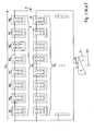
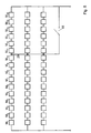
- FIG. 1 a commercial photovoltaic generator 1 is shown, which consists of a number of parallel-connected strands S, which in turn consist of a number, in the embodiment shown eight, connected in series photovoltaic modules M.
- Each photovoltaic module M has series-connected photovoltaic cells 7, as can be seen from the FIG. 1 is apparent.
- Common for a photovoltaic module M is, for example, the use of 60 cells of 1.5 volts open circuit voltage or 130 cells, each about 0.69 volts. In both cases, an idling voltage of about 90 volts results over the module M, in eight modules so about 720 volts. During operation, this voltage drops to about 60 to 65 volts, resulting in a strand voltage Ust of 480 to 510 volts.
- the parallel-connected strands S are connected at their ends to the input 9 of an inverter 11, the output 13 of which generates the generated current, e.g. fed into a network.
- the open circuit voltage of 720 volts is well below the current allowable limit of 1000 volts, which manufacturers of photovoltaic modules specify for their product as the upper limit. In operation, a correspondingly greater safety distance to the 1000 volts is achieved. In the known systems of this type, it would be desirable to fully exploit the maximum allowable voltage of 1000 volts to keep the cross sections of the cables to be laid small.
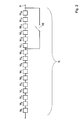
- the photovoltaic system 1 after the FIG. 2 There, a single strand S with this time 16 photovoltaic modules M is shown, which is connected in parallel with other strands, not shown, and is guided to the input 9 of the inverter 11.
- the strand S the double number of modules M to 16 pieces, each of which corresponds to the FIG. 1a is constructed.
- An excess of 20 volts on the admissibility is considered tolerable.
- a short-circuit switch 15 is provided.
- the switch 15 is positioned to short between one tenth, more preferably between one quarter and one half of the modules M.
- the activation of the Switch 15 is made by a limit detector (not shown), which determines when the voltage across the string S exceeds the predetermined value, in this example 1000 volts.
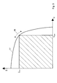
- FIG. 3 the course of the generated current 1 over the accompanying voltage U of a typical photovoltaic system 1 is shown.
- This current / voltage curve 17 is held by means of a MPP (Maximum Power Point) controller to a point at which there is a maximum power.
- This maximum power is the product of the IMPP and the UMPP and corresponds to the hatched field, which in this case occupies a maximum area.
- the MPP controller controls on the curve 17 along the double arrow 19 and has an endeavor to bring the photovoltaic system to the MPP. This point changes constantly depending on the position of the sun, clouds, air pollution and the like.
- the MPP controller could exceed the maximum allowable operating voltage. This is prevented by extending the control algorithm by the condition that the specified voltage value (in this example 1000 volts) must not be exceeded. This condition takes precedence over achieving an optimal power point MPP.
- an output is provided on the MPP controller, which acts on a closing of the switch 15, if this condition is violated for whatever reason.
- FIG. 4 is a typical course of voltage applied to the strand S voltage in the morning startup of the system 1 is shown.
- the curve 21 shows the fictitious curve of the voltage over the time of day in the idle case and the curve 21a in operation with switched inverter 11 after this was switched on reaching the maximum allowable strand voltage of 1000 volts to the energy generated in the network through the output terminals 13th feed.
- the curve 21a follows until the connection process of the inverter of the open-circuit curve 21.
- the curve 21 aims at the exemplary use of 16 modules M per strand S of the open circuit voltage of about 1440 volts. Accordingly, the curve 21a runs under load to the operating voltage of 960 volts (corresponding to 16 times 60 volts). to.
- the short-circuit switch 15 is used, which is turned on when the startup of the system so closed.
- the photovoltaic system works with eleven modules M per strand S on the dotted line 23 and reached around 9:00 clock a power point 25 at which the required minimum power of 1 KW for stable connection to the grid is reached.
- the strand voltage Ust is 700 volts.
- the switch 15 is opened, resulting in a brief drop in voltage result, which is symbolized by the circled in the magnifying glass spikes, as the MPP controller can not compensate for this situation immediately. In reality, the spike is only a few seconds long.
- the MPP controller starts with its control behavior and leads the voltage Ust in a very short time to the curve 23a to a point 27 on a full-voltage operating voltage curve 21a 'with all sixteen modules M.
- the curve 21a' is shown with short dashes and extends from the curve 21a parallel to the left offset from the point 27. From there aspires the Curve 21a 'in the further course of the day with higher sun counter to the maximum value of the operating voltage Ust of 960 volts.
- the grid feed-in starts at 8:45 am, whereas at the operation of the photovoltaic system along the curve it would start at 9:20 am.
- the invention also offers the further advantage of a more effective start-up behavior compared to systems without short-circuit switch 15.
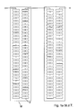
- FIG. 5 It is shown how six of the 16 modules M can be short-circuited together on all strings S of the photovoltaic system.
- the lying after the tenth module M line points 29 each connected to each other and then guided to the short-circuit switch 15.
- the first field F 5 preferably that closest to the inverter 11, is three strands S after FIG. 5 equipped, in which five modules M short-circuited via the short-circuit switch 15.
- the adjacent, second field F 6 all strands S are provided with the short-circuit switch 15.
Landscapes
- Engineering & Computer Science (AREA)
- Power Engineering (AREA)
- Photovoltaic Devices (AREA)
- Control Of Electrical Variables (AREA)
- Supply And Distribution Of Alternating Current (AREA)
- Inverter Devices (AREA)
- Life Sciences & Earth Sciences (AREA)
- Sustainable Development (AREA)
- Sustainable Energy (AREA)
Abstract
Description
- Die Erfindung betrifft einen Photovoltaikgenerator mit einem Feld von mehreren parallel geschalteten Strängen von in Reihe geschalteten Photovoltaikmodulen, wobei ein Teil der Photovoltaikmodule eines Strangs über einen Kurzschlussschalter kurzschließbar ist, dessen Aktivierung bei Überschreitung eines vorgegebenen Spannungswertes über dem Strang erfolgt
- Solche Photovoltaikanlagen sind sattsam bekannt. In der Regel sind diese Anlagen so aufgebaut, dass eine Vielzahl von Strängen parallel geschaltet wird. Die maximale Anzahl der Stränge richtet sich dabei nach der Leistung des Wechselrichters, an den die Stränge angeschlossen sind. Moderne Wechselrichter können bis zu einer Eingangsgleichspannung von ca. 900 Volt ausgelegt sein. Zurzeit ist es üblich, jeden Strang der Anlage aus acht Photovoltaikmodulen aufzubauen, von denen jedes 60 Photovoltaikzellen aufweist. Insgesamt sind somit 480 Zellen in Reihe zueinander geschaltet. An jeder Zelle liegt im Leerlauffall eine Spannung von 1,5 Volt an, was zu einer Strangspannung von 720 Volt führt, was deutlich unter der von den Herstellern der Module angegebenen Maximalspannung von 1000 Volt liegt. Liegt eine höhere Spannung an, kann dies zur Zerstörung der Module und der gesamten Anlage führen.
- Im Betrieb der Anlage sinkt die Leerlaufspannung der Zellen auf eine Betriebsspannung von ca. 1 bis 1,1 Volt, so dass zwischen den Enden der herkömmlichen Stränge eine Spannung zwischen 480 Volt und 510 Volt anliegt. Im Beispiel der später folgenden Figuren wird der Übersichtlichkeit halber von 1 Volt Betriebsspannung pro Zelle ausgegangen, also 60 Volt Spannung über ein einzelnes Photovoltaikmodul mit 60 Zellen. Sollte der Netzbetreiber, an den die Photovoltaikanlage angeschlossen ist, diese aus welchen Gründen auch immer vom Netz nehmen (e.g. Kurzschluss in dem Einspeisekabel) springt die Spannung auf die genannten 720 Volt, was für die Module und die Anlage unkritisch ist.
- Auf der anderen Seite wäre es wünschenswert, die Photovoltaik-Module und auch den Wechselrichter im Normalbetrieb mit einer höheren Spannung als 480 - 510 Volt, idealerweise mit der zulässigen Höchstspannung von 1000 Volt zu betreiben. Dieses ist aber nicht möglich, da dann im Leerlauffall eine Spannung von ca. 1500 Volt zur Zerstörung der Photovoltaik-Module und des Wechselrichters und der Anlage führen würde.
- Zum Betrieb der Photovoltaikanlage mit einer höheren Betriebsspannung ist es aus der
DE 3041078 bekannt, einen Kurzschlussschalter einzusetzen, der einen Teil der Module im Falle einer auftretenden Überspannung kurzschließt. - Diese Maßnahme ist jedoch bei einer großen Anlage mit Hunderten von Feldern mit einem hohen Verdrahtungsaufwand und Schalteraufwand verbunden. Die Felder liegen zum Teil einige Hundert Meter auseinander und es entsteht ein Mehrbedarf an mehreren Kilometern Kabel, die verlegt und angeschlossen werden müssen.
- Der Erfindung liegt daher die Aufgabe zugrunde, eine Photovoltaikgroßanlage mit geringem Leitungsaufwand vor Überspannung bei fehlender Wechselstromeinspeisung zu schützen.
- Diese Aufgabe wird erfindungsgemäß dadurch gelöst, dass bei einer Großanlage mit einer Vielzahl von parallel geschalteten Feldern nur bei einem Teil der Felder der Kurzschlussschalter vorgesehen ist. So brauchen nur die bezüglich zum Wechselrichter und der Steuerung nahegelegenen Felder mit dem Kurzschlussschalter versehen werden, was zu einer erheblichen Kabelersparnis führt. Durch die Reduktion der Spannung an einem oder mehreren Feldern wird das Potential der anderen in der Parallelschaltung befindlicher Felder heruntergezogen auf einen für den Wechselrichter verkraftbaren Spannungswert. Weitere Vorteile und Einzelheiten der Erfindung ergeben sich aus der Beschreibung eines Ausführungsbeispiels anhand der Figuren. Es zeigen:
- Figur 1
- eine schematische Darstellung eines konventionellen Photovoltaikgenerators mit acht Modulen pro Strang;
- Figur 1a
- ein bekanntes Modul mit 60 Photovoltaikzellen;
- Figur 2
- eine schematische Darstellung eines Strangs mit 16 Modulen;
- Figur 3
- ein Diagramm zur Arbeitsweise eines MPP-Reglers;
- Figur 4
- ein Diagramm zum morgendlichen Anfahrverhalten eines erfindungsgemäßen Photovoltaikgenerators;
- Figur 5
- eine Schaltanordnung zum gleichzeitigem Schalten mehrerer miteinander verbundener Stränge; und
- Figur 6
- ein Photovoltaikgenerator mit mehreren Feldern nach der Erfindung.
- In der
Figur 1 ist ein handelsüblicher Photovoltaikgenerator 1 dargestellt, der aus einer Anzahl von parallel geschalteter Stränge S besteht, die wiederum eine Anzahl, im gezeigten Ausführungsbeispiel acht, in Reihe geschalteter Photovoltaikmodulen M bestehen. Jedes Photovoltaikmodul M weist in Reihe geschaltete Photovoltaikzellen 7 auf, wie es aus derFigur 1 ersichtlich ist. Üblich für ein Photovoltaikmodul M ist zum Beispiel der Einsatz von 60 Zellen zu je 1,5 Volt Leerlaufspannung oder auch 130 Zellen zu jeweils ca. 0,69 Volt. In beiden Fällen ergibt sich eine im Leerlauf auftretende Spannung von ca. 90 Volt über das Modul M, bei acht Modulen also ca. 720 Volt. Im Betrieb sinkt diese Spannung auf ca. 60 bis 65 Volt, sodass sich eine Strangspannung Ust von 480 bis 510 Volt ergibt. - Die parallel geschalteten Stränge S sind an ihren Enden an den Eingang 9 eines Wechselrichters 11 gelegt, dessen Ausgang 13 den erzeugten Strom z.B. in ein Netz einspeist.
- Die Leerlaufspannung von 720 Volt liegt deutlich unterhalb der zurzeit zulässigen Grenze von 1000 Volt, die die Hersteller von Photovoltaikmodulen für ihr Produkt als obere Grenze angeben. Im Betrieb wird ein entsprechend noch größerer Sicherheitsabstand zu den 1000 Volt erreicht. Bei den bekannten Anlagen dieser Art wäre es wünschenswert, die zulässige Höchstspannung von 1000 Volt voll auszunutzen, um die Querschnitte der zu verlegenden Kabel klein zu halten. Hierzu dient die Photovoltaikanlage 1 nach der
Figur 2 . Dort ist ein einziger Strang S mit diesmal 16 Photovoltaikmodulen M gezeigt, der zusammen mit anderen nicht gezeigten Strängen parallel geschaltet ist und zu dem Eingang 9 des Wechselrichters 11 geführt ist. Im gezeigten Ausführungsbeispiel weist der Strang S die doppelte Anzahl an Modulen M auf also 16 Stück, von denen jedes entsprechend derFigur 1a aufgebaut ist. Daraus ergibt sich eine unzulässig hohe Leerlaufspannung von 1440 Volt über den Strang S, aber eine zulässig hohe Betriebsspannung von 960 bis 1020 Volt, die an einem der Module M und dem Eingang 9 des Wechselrichters 11 anliegt. Eine Überschreitung um 20 Volt über die Zulässigkeit wird dabei als tolerabel angesehen. - Um bei einer Trennung vom Netz eine Zerstörung von Wechselrichter 11 und Modul M zu verhindern, ist ein Kurzschlussschalter 15 vorgesehen. Der Schalter 15 ist so positioniert, dass er zwischen einem Zehntel, insbesondere zwischen einem Viertel und der Hälfte der Module M kurzschließt. Die Ansteuerung des Schalters 15 wird von einem Grenzwertdetektor (nicht gezeigt) vorgenommen, der ermittelt, wenn die Spannung über den Strang S den vorgebbaren Wert, hier im Beispiel 1000 Volt, übersteigt.
- Im Folgenden wird anhand der
Figuren 3 und4 ein weiterer wesentlicher Vorteil im täglichen Betrieb des erfindungsgemäßen Photovoltaikgenerators 1 erläutert. In derFigur 3 ist der Verlauf des erzeugten Stroms 1 über der einhergehenden Spannung U einer typischen Photovoltaikanlage 1 dargestellt. Diese Strom/Spannungskurve 17 wird mittels eines MPP (Maximum Power Point) Reglers auf einen Punkt gehalten, an dem eine maximale Leistung vorliegt. Diese maximale Leistung ist das Produkt aus dem IMPP und der UMPP und entspricht dem schraffiert markiertem Feld, das in diesem Fall eine maximale Fläche einnimmt. Der MPP-Regler regelt auf der Kurve 17 entlang des Doppelpfeils 19 und hat das Bestreben, die Photovoltaikanlage auf den MPP hinzuführen. Dieser Punkt ändert sich ständig je nach Sonnenstand, Bewölkung, Luftverschmutzung und dergleichen. - Aufgrund der hohen Anzahl an eingebauten Modulen M in einen Strang S könnte der MPP-Regler den zulässigen Höchstwert der Betriebsspannung übersteigen. Dieses wird verhindert, indem der Regelalgorithmus um die Bedingung erweitert wird, dass der vorgegeben Spannungswert (hier im Beispiel 1000 Volt) nicht überschritten werden darf. Diese Bedingung hat Vorrang vor dem Erzielen eines optimalen Leistungspunktes MPP. Vorteilhafterweise wird an dem MPP-Regler ein Ausgang vorgesehen, der auf ein Schließen des Schalters 15 hinwirkt, falls diese Bedingung aus welchen Gründen auch immer verletzt wird.
- In der
Figur 4 ist ein typischer Verlauf der an dem Strang S anliegenden Spannung bei dem morgendlichen Anfahren der Anlage 1 dargestellt. Die Kurve 21 zeigt dabei den fiktiven Verlauf der Spannung über die Tageszeit im Leerlauffall und die Kurve 21a im Betriebsfall mit zugeschaltetem Wechselrichter 11 nachdem dieser bei Erreichen der maximal zulässigen Strangspannung von 1000 Volt zugeschaltet wurde, um die erzeugten Energie in das Netz über die Ausgangsklemmen 13 einzuspeisen. Dabei folgt die Kurve 21a bis zum Zuschaltvorgang des Wechselrichters der Leerlaufkurve 21. Die Kurve 21 strebt bei der beispielhaften Verwendung von 16 Modulen M pro Strang S der Leerlaufspannung von ca. 1440 Volt entgegen. Entsprechend läuft die Kurve 21a unter Last auf die Betriebsspannung von 960 Volt (entsprechend 16 mal 60 Volt) zu. In dem Diagramm derFigur 4 ist außerdem noch eine weitere, gepunktetgestrichelt ausgeführte Kurve 23 gezeigt, die dem Leerlauf- Spannungsverlauf bei geschlossenem Schalter 15 zeigt, also bei den im Beispiel überbrückten fünf Modulen M. Diese Kurve 23 läuft bis zum Zeitpunkt, an dem der Wechselrichter 11 zugeschaltet wird, auf die Leerlaufspannung von den verbleibenden elf in Reihe geschalteten, aktiven Modulen M zu, also auf ca. 990 Volt (entsprechend 11 mal 90 Volt. - Beim morgendlichen Anfahren ohne kurzgeschlossene Module M ergäbe sich der Verlauf nach Kurve 21 und die 1000 Volt oberer zulässiger Spannungswert wären um ca. 8.15 Uhr erreicht. Da die minimal erforderliche Leistung von 1 KW zum Zuschalten des Wechselrichters 11 noch nicht erreicht ist, bricht die Spannung zusammen und muss von Null beginnend neu aufgebaut werden wie es der Verlauf der Kurve 21 a ab 8.15 Uhr darstellt. Die minimal erforderliche Leistung ist von dem verwendeten Wechselrichter 11 abhängig und kann bei einer 2,5 Megawatt Großanlage ca. 15 KW betragen. Ebenso ist eine gewisse Leerlaufspannung erforderlich, damit ein stabiles Ankoppeln des Wechselrichters 11 an das Netz erfolgen kann. Bei dem in
Figur 4 gezeigten Ausführungsbeispiel wird bei einem Vorliegen von 11 Modulen M das Erreichen der Zuschaltkriterien bei einer Strangspannung Ust von 700 Volt angenommen. - Hier kommt der Kurzschlussschalter 15 zum Einsatz, der bei Beginn des Hochfahrens der Anlage eingeschaltet also geschlossen ist. Die Photovoltaikanlage arbeitet mit elf Modulen M pro Strang S auf der gepunktetgestrichelten Linie 23 und erreicht gegen 9.00 Uhr einen Leistungspunkt 25, an dem die erforderliche Mindestleistung von 1 KW zum stabilen Zuschalten auf das Netz erreicht ist. Zu diesem Zeitpunkt beträgt die Strangspannung Ust 700 Volt. Ab diesem Zeitpunkt wird der Schalter 15 geöffnet, was ein kurzzeitiges Absinken der Spannung zur Folge hat, was durch den in der Lupendarstellung eingekreisten Zacken symbolisiert ist, da der MPP-Regler diese Situation nicht sofort ausgleichen kann. In der Realität ist der Zacken nur einige Sekunden lang. Der MPP-Regler setzt mit seinem Regelverhalten ein und führt die Spannung Ust in kürzester Zeit der Kurve 23a zu einem Punkt 27 auf einer Betriebsspannungskurve 21 a' für den vollen Strang S mit allen sechzehn Modulen M. Die Kurve 21a' ist mit kurzen Strichen dargestellt und verläuft von der Kurve 21a parallel nach links versetzt ab von dem Punkt 27. Von dort aus strebt die Kurve 21a' im weiteren Verlauf des Tages mit höher stehender Sonne dem maximalen Wert der Betriebsspannung Ust von 960 Volt entgegen. Im Ergebnis wird eine frühere Leistungseinspeisung in das Netz erzielt, als es ohne den Schalter 15 möglich wäre. Im gezeigten Beispiel setzt die Netzeinspeisung um 8.45 Uhr ein, wohingegen sie beim Betrieb der Photovoltaik-Anlage entlang der Kurve erst um 9.20 Uhr einsetzen würde.
- Abends beim Herunterfahren der Anlage 1 wiederholt sich der Vorgang in umgekehrter Reihenfolge. Die Erfindung bietet also neben den günstigeren Kabelquerschnitten noch den weiteren Vorteil eines effektiveren Anfahrverhaltens im Vergleich zu Anlagen ohne Kurzschlussschalter 15.
- In der
Figur 5 ist gezeigt, wie sechs der 16 Module M gemeinsam bei allen Strängen S der Photovoltaik-Anlage kurzschließbar sind. Dazu dient die nach dem zehnten Modul M liegenden Leitungspunkte 29 jeweils miteinander verbunden und dann zum Kurzschlussschalter 15 geführt. - In der
Figur 6 ist der Aufbau eines erfindungsgemäßen Photovoltaikgenerators gezeigt, bei dem p = 8 Felder F1 bis F8 zu jeweils n = 10 Strängen S1 bis S10 vorgesehen sind. Das erste Feld F5, vorzugsweise das, welches dem Wechselrichter 11 am nächsten liegt, ist mit drei Strängen S nach derFigur 5 ausgestattet, bei dem fünf Module M über den Kurzschlussschalter 15 kurzschließbar sind. Beim benachbarten, zweiten Feld F6 sind alle Stränge S mit dem Kurzschlussschalter 15 versehen. Im Falle eines Kurzschlusses auf der Wechselspannungsseite 13 werden
der oder die Kurzschlussschalter 15 geschlossen und, wenn keine ausreichende Spannungsbegrenzung an der Eingangsseite des Wechselrichters 11 zu verzeichnen ist, werden noch Trennschalter 33 geöffnet, die die Felder F an eine Sammelleitung 35 anschließen, die zu dem Eingang 9 des Wechselrichter 11 führt. Es werden so viele Felder F mit dem Kurzschlussschalter 15 versehen, wie mögliche Ausgleichsströme zwischen den Feldern von den Leitungen und der Sammelleitung 35 toleriert werden können. Sollte eine weitere Reduktion der Spannung am Wechselrichtereingang 9 nötig sein, weil das genannte Herunterziehen des Potentials nicht ausreicht, um auf eine ungefährliche Eingangsspannung am Wechselrichter 11 zu gelangen, so wäre die Anzahl der Module M pro Strang S zu verringern, z.B. von 16 auf 12. -
- S
- Strang
- M
- Photovoltaikmodul
- F
- Feld
- 1
- Photovoltaikgenerator
- 7
- Photovoltaikzelle
- 9
- Eingang Wechselrichter
- 11
- Wechselrichter
- 13
- Ausgang Wechselrichter
- 15
- Kurzschussschalter
- 17
- Strom/Spannungskurve
- 19
- Doppelpfeil
- 21
- Leerlaufkurve 16 Module, durchgezogene Linie
- 21 a
- Lastkurve 16 Module, lang-gestrichelte Linie
- 21a'
- Lastkurve ab Schalteröffnung an Punkt 27 entsprechend dann 16 Module
- 23
- Leerlauf-Spannungsverlauf bis Schalteröffnung entsprechend elf Module, gestrichelt / gepunktete Linie bis Zuschaltpunkt 25
- 23a
- MPP Regelkurve im Sekundenbereich zwischen Schalteröffnung und Erreichen der Lastkurve 21a', hohl-gepunktete Linie
- 25
- Leistungspunkt
- 27
- Spannungspunkt
- 29
- Leitungspunkt
- 33
- Trennschalter
- 35
- Sammelleitung
Claims (10)
- Photovoltaikgenerator (1) mit einem Feld von mehreren parallel geschalteten Strängen (S) von in Reihe geschalteten Photovoltaikmodulen (M), wobei ein Teil der Photovoltaikmodule (M) eines Strangs (S) über einen Kurzschlussschalter (15) kurzschließbar ist, dessen Aktivierung bei Überschreitung eines vorgegebenen Spannungswertes über dem Strang (S) erfolgt, dadurch gekennzeichnet, dass eine Vielzahl von parallel geschalteten Feldern vorgesehen ist, wobei nur bei einem Teil der Felder der Kurzschlussschalter (15) vorgesehen ist.
- Photovoltaikgenerator nach Anspruch 1, dadurch gekennzeichnet, dass nur ein einziges Feld mit dem Kurzschlussschalter ausgerüstet ist.
- Photovoltaikgenerator nach Anspruch 1 oder 2, dadurch gekennzeichnet, dass die Felder über einen Trennschalter aus der Parallelschaltung herausnehmbar sind.
- Photovoltaikgenerator nach Anspruch 1 oder 2, dadurch gekennzeichnet, dass der Kurzschlussschalter ein gemeinsamer Schalter (15) zum Kurzschließen der Photovoltaikmodule (M) mehrerer Stränge (S) ist und der Kurzschlussschalter (15) den Stromfluss zu den mehreren Strängen (S) unterbricht oder freigibt.
- Photovoltaikgenerator nach einem der Ansprüche 1 bis 4, dadurch gekennzeichnet, dass der Kurzschlussschalter (15) so angeordnet ist, dass die Hälfte der Photovoltaikmodule (M) kurzgeschlossen wird.
- Photovoltaikgenerator nach einem der Ansprüche 1 bis 5, dadurch gekennzeichnet, dass wenigstens zwei Stränge (S) mit je einem Kurzschlussschalter (15) ausgestattet sind, die unterschiedlich viele Module (M) in den Strängen (S) kurzschließen.
- Photovoltaikgenerator nach einem der Ansprüche 1 bis 6, dadurch gekennzeichnet, dass das Signal zur Aktivierung des Kurzschlussschalters (15) von einem Ausgang eines Reglers für die maximale Leistung (MPP-Regler) genommen wird.
- Photovoltaikgenerator nach einem der Ansprüche 1 bis 7, dadurch gekennzeichnet, dass der vorgegebene Spannungswert im Bereich von 900 Volt bis 1200 Volt liegt.
- Photovoltaikgenerator nach einem der Ansprüche 1 bis 8, dadurch gekennzeichnet, dass ein Viertel bis die Hälfte aller Photovoltaikmodule (M) kurzschließbar ist.
- Photovoltaikgenerator nach einem der Ansprüche 1 bis 9, dadurch gekennzeichnet, dass mehrere Stränge (S) hinter derselben Anzahl an Photovoltaikmodulen (M) miteinander verbunden sind und der Schalter (15) alle zwischen dem Zehntel und der Hälfte liegenden Photovoltaikmodule (M) aller mehreren Stränge gleichzeitig kurzschließt. (Figur 5)
Applications Claiming Priority (1)
| Application Number | Priority Date | Filing Date | Title |
|---|---|---|---|
| DE102010009120A DE102010009120B4 (de) | 2010-02-24 | 2010-02-24 | Photovoltaikgenerator |
Publications (3)
| Publication Number | Publication Date |
|---|---|
| EP2367253A2 true EP2367253A2 (de) | 2011-09-21 |
| EP2367253A3 EP2367253A3 (de) | 2013-12-25 |
| EP2367253B1 EP2367253B1 (de) | 2018-04-11 |
Family
ID=44259747
Family Applications (1)
| Application Number | Title | Priority Date | Filing Date |
|---|---|---|---|
| EP11000852.1A Not-in-force EP2367253B1 (de) | 2010-02-24 | 2011-02-03 | Photovoltaikfelder, teilweise mit Schalter zum Kurzschließen von Modulen |
Country Status (4)
| Country | Link |
|---|---|
| US (1) | US8809669B2 (de) |
| EP (1) | EP2367253B1 (de) |
| DE (1) | DE102010009120B4 (de) |
| ES (1) | ES2675670T3 (de) |
Cited By (1)
| Publication number | Priority date | Publication date | Assignee | Title |
|---|---|---|---|---|
| WO2015172959A1 (en) * | 2014-05-14 | 2015-11-19 | Sma Solar Technology Ag | Centralized dc curtailment for overvoltage protection |
Families Citing this family (14)
| Publication number | Priority date | Publication date | Assignee | Title |
|---|---|---|---|---|
| ATE555531T1 (de) * | 2009-08-06 | 2012-05-15 | Sma Solar Technology Ag | Rückstromsensor für parallel geschaltete solarmodule |
| US8194375B2 (en) * | 2010-01-19 | 2012-06-05 | General Electric Company | Open circuit voltage protection system and method |
| US8970065B2 (en) * | 2011-08-04 | 2015-03-03 | Eaton Corporation | System and method for increasing voltage in a photovoltaic inverter |
| US20130076144A1 (en) * | 2011-09-28 | 2013-03-28 | General Electric Company | System and method for limiting photovoltaic string voltage |
| US8630077B2 (en) * | 2011-12-22 | 2014-01-14 | Sunpower Corporation | Circuits and methods for limiting open circuit voltage of photovoltaic strings |
| DE102012101340B4 (de) * | 2012-02-20 | 2015-11-19 | Sma Solar Technology Ag | Schutz von Photovoltaikmodulen eines Photovoltaikgenerators vor Überspannungen gegenüber Erde |
| US9559518B2 (en) * | 2012-05-01 | 2017-01-31 | First Solar, Inc. | System and method of solar module biasing |
| EP3142153B1 (de) * | 2015-09-12 | 2020-04-01 | IMEC vzw | Neukonfigurierbares photovoltaikmodul |
| DE102016105930A1 (de) | 2016-03-31 | 2017-10-05 | Sma Solar Technology Ag | Solarmodul, Betriebsverfahren Für ein Solarmodul und Photovoltaikanlage |
| DE102016118039A1 (de) | 2016-09-23 | 2018-03-29 | Sma Solar Technology Ag | Solarmodul, Photovoltaikanlage und Verfahren zur Spannungsbegrenzung |
| DE102016125219B4 (de) | 2016-12-21 | 2019-01-17 | Sma Solar Technology Ag | Schaltung zur Spannungsbegrenzung in einem Photovoltaikfeld, Photovoltaikfeld und Verfahren zur Spannungsbegrenzung |
| CN111565020A (zh) * | 2019-02-14 | 2020-08-21 | 阳光电源股份有限公司 | 一种组件限压方法及其应用装置和系统 |
| CN111668868A (zh) | 2020-05-08 | 2020-09-15 | 华为技术有限公司 | 一种光伏发电系统及方法 |
| ES2967960B2 (es) * | 2023-11-13 | 2026-01-15 | Energias Renovables Erin S L | Dispositivo de control de voltaje y desconexión de módulos fotovoltaicos para string |
Citations (1)
| Publication number | Priority date | Publication date | Assignee | Title |
|---|---|---|---|---|
| DE3041078A1 (de) | 1980-10-29 | 1982-06-03 | Licentia Patent-Verwaltungs-Gmbh, 6000 Frankfurt | Verfahren zur spannungsbegrenzung fuer photovoltaische generatoren |
Family Cites Families (6)
| Publication number | Priority date | Publication date | Assignee | Title |
|---|---|---|---|---|
| JP3271730B2 (ja) * | 1994-04-28 | 2002-04-08 | キヤノン株式会社 | 発電システムの充電制御装置 |
| DE102005017835B3 (de) * | 2005-04-18 | 2006-11-23 | Beck Energy Gmbh | Photovoltaikgenerator mit Thermoschalterelement |
| DE102006060815B4 (de) * | 2006-09-21 | 2013-05-29 | Solarworld Innovations Gmbh | Solarenergieerzeugungsanlage |
| US8473250B2 (en) * | 2006-12-06 | 2013-06-25 | Solaredge, Ltd. | Monitoring of distributed power harvesting systems using DC power sources |
| CN201234223Y (zh) * | 2008-07-01 | 2009-05-06 | 比亚迪股份有限公司 | 太阳能供电装置 |
| EP2311163A4 (de) * | 2008-07-01 | 2013-08-21 | Satcon Technology Corp | Photovoltaik-gleichstrom-gleichstrom-mikroumrichter |
-
2010
- 2010-02-24 DE DE102010009120A patent/DE102010009120B4/de not_active Expired - Fee Related
-
2011
- 2011-02-03 ES ES11000852.1T patent/ES2675670T3/es active Active
- 2011-02-03 EP EP11000852.1A patent/EP2367253B1/de not_active Not-in-force
- 2011-02-24 US US13/034,117 patent/US8809669B2/en not_active Expired - Fee Related
Patent Citations (1)
| Publication number | Priority date | Publication date | Assignee | Title |
|---|---|---|---|---|
| DE3041078A1 (de) | 1980-10-29 | 1982-06-03 | Licentia Patent-Verwaltungs-Gmbh, 6000 Frankfurt | Verfahren zur spannungsbegrenzung fuer photovoltaische generatoren |
Cited By (1)
| Publication number | Priority date | Publication date | Assignee | Title |
|---|---|---|---|---|
| WO2015172959A1 (en) * | 2014-05-14 | 2015-11-19 | Sma Solar Technology Ag | Centralized dc curtailment for overvoltage protection |
Also Published As
| Publication number | Publication date |
|---|---|
| DE102010009120A1 (de) | 2011-08-25 |
| US20110203635A1 (en) | 2011-08-25 |
| EP2367253B1 (de) | 2018-04-11 |
| US8809669B2 (en) | 2014-08-19 |
| DE102010009120B4 (de) | 2011-09-01 |
| ES2675670T3 (es) | 2018-07-11 |
| EP2367253A3 (de) | 2013-12-25 |
Similar Documents
| Publication | Publication Date | Title |
|---|---|---|
| EP2367253B1 (de) | Photovoltaikfelder, teilweise mit Schalter zum Kurzschließen von Modulen | |
| EP3345301B1 (de) | Sichere photovoltaik-anlage | |
| EP1914857B1 (de) | Schaltungseinrichtung und Verfahren, insbesondere für Photovoltaik-Generatoren | |
| EP2284973B1 (de) | Rückstromsensor für parallel geschaltete Solarmodule | |
| EP2920858B1 (de) | Verfahren und vorrichtung zum schutz mehrerer strings eines photovoltaikgenerators vor rückströmen | |
| EP2619842B1 (de) | Energieversorgungsnetz und verfahren zum laden mindestens einer als energiespeicher für einen gleichspannungszwischenkreis dienenden energiespeicherzelle in einem energieversorgungsnetz | |
| EP2276137B1 (de) | Photovoltaikanlage | |
| DE102009025363B4 (de) | Anfahrquelle Wechselrichter | |
| EP2148417A1 (de) | Wechselrichterschaltungsanordnung für einen Photovoltaikgenerator mit mehreren eingangs seriell geschalteten Stromrichtern | |
| DE102013103753A1 (de) | Photovolatische energieerzeugungsanlage und verfahren zum betreiben einer pv-anlage | |
| DE102011076553A1 (de) | Steuerung des gleichstromflusses einer photovoltaikanlage | |
| DE102010055550A1 (de) | Wechselrichter, Energieerzeugungsanlage und Verfahren zum Betrieb einer Energieerzeugungsanlage | |
| DE102012113130A1 (de) | Adaptives Leistungsumwandlungssystem | |
| DE102010026778A1 (de) | Vorrichtung zur Bereitstellung einer Eingangsgleichspannung für einen Photovol taikwechselrichter und Photovoltaikanlage mit dieser | |
| DE102016117049A1 (de) | Multistrang-Photovoltaik-Anlage, Verfahren zum Betrieb einer solchen und Rückstromschutzschaltung für eine solche | |
| WO2015004034A2 (de) | Elektrische anordnung mit einem wechselrichter und zwischenschaltgerät für die elektrische anordnung | |
| EP2511956B1 (de) | Drei-Schalter Überspannungsschutz für eine Photovoltaikanlage | |
| EP3361596B1 (de) | Batterie mit einem batteriemanagementsystem, das eine elektronische schalteinrichtung umfasst | |
| EP3220527A1 (de) | Modularer mehrstufenumrichter | |
| DE102015115284B3 (de) | Schutzvorrichtung für eine elektrische Energieversorgungseinrichtung und elektrische Energieversorgungseinrichtung mit einer derartigen Schutzvorrichtung | |
| DE102011000737B4 (de) | Schutzeinrichtung für eine Photovoltaikanlage, Photovoltaikmodul mit einer solchen Schutzeinrichtung sowie Betriebsverfahren für eine solche Schutzeinrichtung | |
| DE202006001063U1 (de) | Wechselrichter zur Einspeisung elektrischer, mit einer PV-Anlage o.dgl. erzeugter Energie in ein Energieversorgungsnetz | |
| WO2014154233A1 (de) | Sammelbox zum elektrischen verbinden einer mehrzahl von photovoltaikgeneratoren und photovoltaische energieerzeugungsanlage | |
| EP2355170A2 (de) | Steuerung für Fotovoltaik-Anlagen | |
| DE102009042084A1 (de) | Wartungsarmes elektronisches Bauelement zur Verhinderung von Rückströmen bei gleichzeitigem Schutz vor Überströmen in Photovoltaikanlagen |
Legal Events
| Date | Code | Title | Description |
|---|---|---|---|
| PUAI | Public reference made under article 153(3) epc to a published international application that has entered the european phase |
Free format text: ORIGINAL CODE: 0009012 |
|
| AK | Designated contracting states |
Kind code of ref document: A2 Designated state(s): AL AT BE BG CH CY CZ DE DK EE ES FI FR GB GR HR HU IE IS IT LI LT LU LV MC MK MT NL NO PL PT RO RS SE SI SK SM TR |
|
| AX | Request for extension of the european patent |
Extension state: BA ME |
|
| PUAL | Search report despatched |
Free format text: ORIGINAL CODE: 0009013 |
|
| AK | Designated contracting states |
Kind code of ref document: A3 Designated state(s): AL AT BE BG CH CY CZ DE DK EE ES FI FR GB GR HR HU IE IS IT LI LT LU LV MC MK MT NL NO PL PT RO RS SE SI SK SM TR |
|
| AX | Request for extension of the european patent |
Extension state: BA ME |
|
| RIC1 | Information provided on ipc code assigned before grant |
Ipc: H02N 6/00 20060101ALI20131118BHEP Ipc: H02J 3/38 20060101ALI20131118BHEP Ipc: H01L 31/02 20060101ALI20131118BHEP Ipc: H02H 9/04 20060101AFI20131118BHEP |
|
| 17P | Request for examination filed |
Effective date: 20140625 |
|
| RBV | Designated contracting states (corrected) |
Designated state(s): AL AT BE BG CH CY CZ DE DK EE ES FI FR GB GR HR HU IE IS IT LI LT LU LV MC MK MT NL NO PL PT RO RS SE SI SK SM TR |
|
| REG | Reference to a national code |
Ref country code: DE Ref legal event code: R079 Ref document number: 502011014014 Country of ref document: DE Free format text: PREVIOUS MAIN CLASS: H02H0009040000 Ipc: H02J0003380000 |
|
| GRAP | Despatch of communication of intention to grant a patent |
Free format text: ORIGINAL CODE: EPIDOSNIGR1 |
|
| STAA | Information on the status of an ep patent application or granted ep patent |
Free format text: STATUS: GRANT OF PATENT IS INTENDED |
|
| RIC1 | Information provided on ipc code assigned before grant |
Ipc: H02J 3/38 20060101AFI20171130BHEP Ipc: H01L 31/02 20060101ALI20171130BHEP |
|
| INTG | Intention to grant announced |
Effective date: 20171222 |
|
| GRAS | Grant fee paid |
Free format text: ORIGINAL CODE: EPIDOSNIGR3 |
|
| GRAA | (expected) grant |
Free format text: ORIGINAL CODE: 0009210 |
|
| STAA | Information on the status of an ep patent application or granted ep patent |
Free format text: STATUS: THE PATENT HAS BEEN GRANTED |
|
| AK | Designated contracting states |
Kind code of ref document: B1 Designated state(s): AL AT BE BG CH CY CZ DE DK EE ES FI FR GB GR HR HU IE IS IT LI LT LU LV MC MK MT NL NO PL PT RO RS SE SI SK SM TR |
|
| REG | Reference to a national code |
Ref country code: GB Ref legal event code: FG4D Free format text: NOT ENGLISH |
|
| REG | Reference to a national code |
Ref country code: CH Ref legal event code: EP |
|
| REG | Reference to a national code |
Ref country code: AT Ref legal event code: REF Ref document number: 989002 Country of ref document: AT Kind code of ref document: T Effective date: 20180415 |
|
| REG | Reference to a national code |
Ref country code: IE Ref legal event code: FG4D Free format text: LANGUAGE OF EP DOCUMENT: GERMAN |
|
| REG | Reference to a national code |
Ref country code: DE Ref legal event code: R096 Ref document number: 502011014014 Country of ref document: DE |
|
| REG | Reference to a national code |
Ref country code: ES Ref legal event code: FG2A Ref document number: 2675670 Country of ref document: ES Kind code of ref document: T3 Effective date: 20180711 |
|
| REG | Reference to a national code |
Ref country code: NL Ref legal event code: FP |
|
| REG | Reference to a national code |
Ref country code: LT Ref legal event code: MG4D |
|
| PG25 | Lapsed in a contracting state [announced via postgrant information from national office to epo] |
Ref country code: SE Free format text: LAPSE BECAUSE OF FAILURE TO SUBMIT A TRANSLATION OF THE DESCRIPTION OR TO PAY THE FEE WITHIN THE PRESCRIBED TIME-LIMIT Effective date: 20180411 Ref country code: AL Free format text: LAPSE BECAUSE OF FAILURE TO SUBMIT A TRANSLATION OF THE DESCRIPTION OR TO PAY THE FEE WITHIN THE PRESCRIBED TIME-LIMIT Effective date: 20180411 Ref country code: FI Free format text: LAPSE BECAUSE OF FAILURE TO SUBMIT A TRANSLATION OF THE DESCRIPTION OR TO PAY THE FEE WITHIN THE PRESCRIBED TIME-LIMIT Effective date: 20180411 Ref country code: BG Free format text: LAPSE BECAUSE OF FAILURE TO SUBMIT A TRANSLATION OF THE DESCRIPTION OR TO PAY THE FEE WITHIN THE PRESCRIBED TIME-LIMIT Effective date: 20180711 Ref country code: NO Free format text: LAPSE BECAUSE OF FAILURE TO SUBMIT A TRANSLATION OF THE DESCRIPTION OR TO PAY THE FEE WITHIN THE PRESCRIBED TIME-LIMIT Effective date: 20180711 Ref country code: PL Free format text: LAPSE BECAUSE OF FAILURE TO SUBMIT A TRANSLATION OF THE DESCRIPTION OR TO PAY THE FEE WITHIN THE PRESCRIBED TIME-LIMIT Effective date: 20180411 Ref country code: LT Free format text: LAPSE BECAUSE OF FAILURE TO SUBMIT A TRANSLATION OF THE DESCRIPTION OR TO PAY THE FEE WITHIN THE PRESCRIBED TIME-LIMIT Effective date: 20180411 |
|
| PG25 | Lapsed in a contracting state [announced via postgrant information from national office to epo] |
Ref country code: GR Free format text: LAPSE BECAUSE OF FAILURE TO SUBMIT A TRANSLATION OF THE DESCRIPTION OR TO PAY THE FEE WITHIN THE PRESCRIBED TIME-LIMIT Effective date: 20180712 Ref country code: RS Free format text: LAPSE BECAUSE OF FAILURE TO SUBMIT A TRANSLATION OF THE DESCRIPTION OR TO PAY THE FEE WITHIN THE PRESCRIBED TIME-LIMIT Effective date: 20180411 Ref country code: HR Free format text: LAPSE BECAUSE OF FAILURE TO SUBMIT A TRANSLATION OF THE DESCRIPTION OR TO PAY THE FEE WITHIN THE PRESCRIBED TIME-LIMIT Effective date: 20180411 Ref country code: LV Free format text: LAPSE BECAUSE OF FAILURE TO SUBMIT A TRANSLATION OF THE DESCRIPTION OR TO PAY THE FEE WITHIN THE PRESCRIBED TIME-LIMIT Effective date: 20180411 |
|
| PG25 | Lapsed in a contracting state [announced via postgrant information from national office to epo] |
Ref country code: PT Free format text: LAPSE BECAUSE OF FAILURE TO SUBMIT A TRANSLATION OF THE DESCRIPTION OR TO PAY THE FEE WITHIN THE PRESCRIBED TIME-LIMIT Effective date: 20180813 |
|
| REG | Reference to a national code |
Ref country code: DE Ref legal event code: R097 Ref document number: 502011014014 Country of ref document: DE |
|
| PG25 | Lapsed in a contracting state [announced via postgrant information from national office to epo] |
Ref country code: CZ Free format text: LAPSE BECAUSE OF FAILURE TO SUBMIT A TRANSLATION OF THE DESCRIPTION OR TO PAY THE FEE WITHIN THE PRESCRIBED TIME-LIMIT Effective date: 20180411 Ref country code: RO Free format text: LAPSE BECAUSE OF FAILURE TO SUBMIT A TRANSLATION OF THE DESCRIPTION OR TO PAY THE FEE WITHIN THE PRESCRIBED TIME-LIMIT Effective date: 20180411 Ref country code: EE Free format text: LAPSE BECAUSE OF FAILURE TO SUBMIT A TRANSLATION OF THE DESCRIPTION OR TO PAY THE FEE WITHIN THE PRESCRIBED TIME-LIMIT Effective date: 20180411 Ref country code: DK Free format text: LAPSE BECAUSE OF FAILURE TO SUBMIT A TRANSLATION OF THE DESCRIPTION OR TO PAY THE FEE WITHIN THE PRESCRIBED TIME-LIMIT Effective date: 20180411 Ref country code: SK Free format text: LAPSE BECAUSE OF FAILURE TO SUBMIT A TRANSLATION OF THE DESCRIPTION OR TO PAY THE FEE WITHIN THE PRESCRIBED TIME-LIMIT Effective date: 20180411 |
|
| PLBE | No opposition filed within time limit |
Free format text: ORIGINAL CODE: 0009261 |
|
| STAA | Information on the status of an ep patent application or granted ep patent |
Free format text: STATUS: NO OPPOSITION FILED WITHIN TIME LIMIT |
|
| PG25 | Lapsed in a contracting state [announced via postgrant information from national office to epo] |
Ref country code: SM Free format text: LAPSE BECAUSE OF FAILURE TO SUBMIT A TRANSLATION OF THE DESCRIPTION OR TO PAY THE FEE WITHIN THE PRESCRIBED TIME-LIMIT Effective date: 20180411 |
|
| 26N | No opposition filed |
Effective date: 20190114 |
|
| PGFP | Annual fee paid to national office [announced via postgrant information from national office to epo] |
Ref country code: NL Payment date: 20190219 Year of fee payment: 9 |
|
| PGFP | Annual fee paid to national office [announced via postgrant information from national office to epo] |
Ref country code: IT Payment date: 20190222 Year of fee payment: 9 Ref country code: GB Payment date: 20190221 Year of fee payment: 9 Ref country code: ES Payment date: 20190319 Year of fee payment: 9 Ref country code: DE Payment date: 20190219 Year of fee payment: 9 |
|
| PG25 | Lapsed in a contracting state [announced via postgrant information from national office to epo] |
Ref country code: SI Free format text: LAPSE BECAUSE OF FAILURE TO SUBMIT A TRANSLATION OF THE DESCRIPTION OR TO PAY THE FEE WITHIN THE PRESCRIBED TIME-LIMIT Effective date: 20180411 |
|
| PGFP | Annual fee paid to national office [announced via postgrant information from national office to epo] |
Ref country code: FR Payment date: 20190221 Year of fee payment: 9 Ref country code: BE Payment date: 20190219 Year of fee payment: 9 |
|
| REG | Reference to a national code |
Ref country code: CH Ref legal event code: PL |
|
| PG25 | Lapsed in a contracting state [announced via postgrant information from national office to epo] |
Ref country code: MC Free format text: LAPSE BECAUSE OF FAILURE TO SUBMIT A TRANSLATION OF THE DESCRIPTION OR TO PAY THE FEE WITHIN THE PRESCRIBED TIME-LIMIT Effective date: 20180411 Ref country code: LU Free format text: LAPSE BECAUSE OF NON-PAYMENT OF DUE FEES Effective date: 20190203 |
|
| REG | Reference to a national code |
Ref country code: IE Ref legal event code: MM4A |
|
| PG25 | Lapsed in a contracting state [announced via postgrant information from national office to epo] |
Ref country code: CH Free format text: LAPSE BECAUSE OF NON-PAYMENT OF DUE FEES Effective date: 20190228 Ref country code: LI Free format text: LAPSE BECAUSE OF NON-PAYMENT OF DUE FEES Effective date: 20190228 |
|
| PG25 | Lapsed in a contracting state [announced via postgrant information from national office to epo] |
Ref country code: IE Free format text: LAPSE BECAUSE OF NON-PAYMENT OF DUE FEES Effective date: 20190203 |
|
| PG25 | Lapsed in a contracting state [announced via postgrant information from national office to epo] |
Ref country code: TR Free format text: LAPSE BECAUSE OF FAILURE TO SUBMIT A TRANSLATION OF THE DESCRIPTION OR TO PAY THE FEE WITHIN THE PRESCRIBED TIME-LIMIT Effective date: 20180411 |
|
| REG | Reference to a national code |
Ref country code: AT Ref legal event code: MM01 Ref document number: 989002 Country of ref document: AT Kind code of ref document: T Effective date: 20190203 |
|
| PG25 | Lapsed in a contracting state [announced via postgrant information from national office to epo] |
Ref country code: AT Free format text: LAPSE BECAUSE OF NON-PAYMENT OF DUE FEES Effective date: 20190203 |
|
| PG25 | Lapsed in a contracting state [announced via postgrant information from national office to epo] |
Ref country code: MT Free format text: LAPSE BECAUSE OF FAILURE TO SUBMIT A TRANSLATION OF THE DESCRIPTION OR TO PAY THE FEE WITHIN THE PRESCRIBED TIME-LIMIT Effective date: 20180411 |
|
| REG | Reference to a national code |
Ref country code: DE Ref legal event code: R119 Ref document number: 502011014014 Country of ref document: DE |
|
| REG | Reference to a national code |
Ref country code: NL Ref legal event code: MM Effective date: 20200301 |
|
| GBPC | Gb: european patent ceased through non-payment of renewal fee |
Effective date: 20200203 |
|
| REG | Reference to a national code |
Ref country code: BE Ref legal event code: MM Effective date: 20200229 |
|
| PG25 | Lapsed in a contracting state [announced via postgrant information from national office to epo] |
Ref country code: NL Free format text: LAPSE BECAUSE OF NON-PAYMENT OF DUE FEES Effective date: 20200301 |
|
| PG25 | Lapsed in a contracting state [announced via postgrant information from national office to epo] |
Ref country code: GB Free format text: LAPSE BECAUSE OF NON-PAYMENT OF DUE FEES Effective date: 20200203 Ref country code: FR Free format text: LAPSE BECAUSE OF NON-PAYMENT OF DUE FEES Effective date: 20200229 Ref country code: DE Free format text: LAPSE BECAUSE OF NON-PAYMENT OF DUE FEES Effective date: 20200901 |
|
| PG25 | Lapsed in a contracting state [announced via postgrant information from national office to epo] |
Ref country code: BE Free format text: LAPSE BECAUSE OF NON-PAYMENT OF DUE FEES Effective date: 20200229 |
|
| PG25 | Lapsed in a contracting state [announced via postgrant information from national office to epo] |
Ref country code: CY Free format text: LAPSE BECAUSE OF FAILURE TO SUBMIT A TRANSLATION OF THE DESCRIPTION OR TO PAY THE FEE WITHIN THE PRESCRIBED TIME-LIMIT Effective date: 20180411 |
|
| PG25 | Lapsed in a contracting state [announced via postgrant information from national office to epo] |
Ref country code: IS Free format text: LAPSE BECAUSE OF FAILURE TO SUBMIT A TRANSLATION OF THE DESCRIPTION OR TO PAY THE FEE WITHIN THE PRESCRIBED TIME-LIMIT Effective date: 20180811 |
|
| PG25 | Lapsed in a contracting state [announced via postgrant information from national office to epo] |
Ref country code: HU Free format text: LAPSE BECAUSE OF FAILURE TO SUBMIT A TRANSLATION OF THE DESCRIPTION OR TO PAY THE FEE WITHIN THE PRESCRIBED TIME-LIMIT; INVALID AB INITIO Effective date: 20110203 |
|
| PG25 | Lapsed in a contracting state [announced via postgrant information from national office to epo] |
Ref country code: ES Free format text: LAPSE BECAUSE OF NON-PAYMENT OF DUE FEES Effective date: 20200204 |
|
| PG25 | Lapsed in a contracting state [announced via postgrant information from national office to epo] |
Ref country code: IT Free format text: LAPSE BECAUSE OF NON-PAYMENT OF DUE FEES Effective date: 20200203 |
|
| PG25 | Lapsed in a contracting state [announced via postgrant information from national office to epo] |
Ref country code: MK Free format text: LAPSE BECAUSE OF FAILURE TO SUBMIT A TRANSLATION OF THE DESCRIPTION OR TO PAY THE FEE WITHIN THE PRESCRIBED TIME-LIMIT Effective date: 20180411 |