EP2367261A2 - Appareil de source d'alimentation à courant continu - Google Patents
Appareil de source d'alimentation à courant continu Download PDFInfo
- Publication number
- EP2367261A2 EP2367261A2 EP20110158349 EP11158349A EP2367261A2 EP 2367261 A2 EP2367261 A2 EP 2367261A2 EP 20110158349 EP20110158349 EP 20110158349 EP 11158349 A EP11158349 A EP 11158349A EP 2367261 A2 EP2367261 A2 EP 2367261A2
- Authority
- EP
- European Patent Office
- Prior art keywords
- voltage
- secondary battery
- ion capacitor
- capacitor unit
- power source
- Prior art date
- Legal status (The legal status is an assumption and is not a legal conclusion. Google has not performed a legal analysis and makes no representation as to the accuracy of the status listed.)
- Withdrawn
Links
Images





Classifications
-
- H—ELECTRICITY
- H02—GENERATION; CONVERSION OR DISTRIBUTION OF ELECTRIC POWER
- H02J—ELECTRIC POWER NETWORKS; CIRCUIT ARRANGEMENTS OR SYSTEMS FOR SUPPLYING OR DISTRIBUTING ELECTRIC POWER; SYSTEMS FOR STORING ELECTRIC ENERGY
- H02J7/00—Circuit arrangements for charging or discharging batteries or for supplying loads from batteries
- H02J7/34—Parallel operation in networks using both storage and other DC sources, e.g. providing buffering
- H02J7/345—Parallel operation in networks using both storage and other DC sources, e.g. providing buffering using capacitors as storage or buffering devices
-
- B—PERFORMING OPERATIONS; TRANSPORTING
- B60—VEHICLES IN GENERAL
- B60L—PROPULSION OF ELECTRICALLY-PROPELLED VEHICLES; SUPPLYING ELECTRIC POWER FOR AUXILIARY EQUIPMENT OF ELECTRICALLY-PROPELLED VEHICLES; ELECTRODYNAMIC BRAKE SYSTEMS FOR VEHICLES IN GENERAL; MAGNETIC SUSPENSION OR LEVITATION FOR VEHICLES; MONITORING OPERATING VARIABLES OF ELECTRICALLY-PROPELLED VEHICLES; ELECTRIC SAFETY DEVICES FOR ELECTRICALLY-PROPELLED VEHICLES
- B60L53/00—Methods of charging batteries, specially adapted for electric vehicles; Charging stations or on-board charging equipment therefor; Exchange of energy storage elements in electric vehicles
- B60L53/50—Charging stations characterised by energy-storage or power-generation means
- B60L53/55—Capacitors
-
- B—PERFORMING OPERATIONS; TRANSPORTING
- B60—VEHICLES IN GENERAL
- B60L—PROPULSION OF ELECTRICALLY-PROPELLED VEHICLES; SUPPLYING ELECTRIC POWER FOR AUXILIARY EQUIPMENT OF ELECTRICALLY-PROPELLED VEHICLES; ELECTRODYNAMIC BRAKE SYSTEMS FOR VEHICLES IN GENERAL; MAGNETIC SUSPENSION OR LEVITATION FOR VEHICLES; MONITORING OPERATING VARIABLES OF ELECTRICALLY-PROPELLED VEHICLES; ELECTRIC SAFETY DEVICES FOR ELECTRICALLY-PROPELLED VEHICLES
- B60L3/00—Electric devices on electrically-propelled vehicles for safety purposes; Monitoring operating variables, e.g. speed, deceleration or energy consumption
- B60L3/0023—Detecting, eliminating, remedying or compensating for drive train abnormalities, e.g. failures within the drive train
- B60L3/0046—Detecting, eliminating, remedying or compensating for drive train abnormalities, e.g. failures within the drive train relating to electric energy storage systems, e.g. batteries or capacitors
-
- B—PERFORMING OPERATIONS; TRANSPORTING
- B60—VEHICLES IN GENERAL
- B60L—PROPULSION OF ELECTRICALLY-PROPELLED VEHICLES; SUPPLYING ELECTRIC POWER FOR AUXILIARY EQUIPMENT OF ELECTRICALLY-PROPELLED VEHICLES; ELECTRODYNAMIC BRAKE SYSTEMS FOR VEHICLES IN GENERAL; MAGNETIC SUSPENSION OR LEVITATION FOR VEHICLES; MONITORING OPERATING VARIABLES OF ELECTRICALLY-PROPELLED VEHICLES; ELECTRIC SAFETY DEVICES FOR ELECTRICALLY-PROPELLED VEHICLES
- B60L50/00—Electric propulsion with power supplied within the vehicle
- B60L50/10—Electric propulsion with power supplied within the vehicle using propulsion power supplied by engine-driven generators, e.g. generators driven by combustion engines
- B60L50/15—Electric propulsion with power supplied within the vehicle using propulsion power supplied by engine-driven generators, e.g. generators driven by combustion engines with additional electric power supply
-
- B—PERFORMING OPERATIONS; TRANSPORTING
- B60—VEHICLES IN GENERAL
- B60L—PROPULSION OF ELECTRICALLY-PROPELLED VEHICLES; SUPPLYING ELECTRIC POWER FOR AUXILIARY EQUIPMENT OF ELECTRICALLY-PROPELLED VEHICLES; ELECTRODYNAMIC BRAKE SYSTEMS FOR VEHICLES IN GENERAL; MAGNETIC SUSPENSION OR LEVITATION FOR VEHICLES; MONITORING OPERATING VARIABLES OF ELECTRICALLY-PROPELLED VEHICLES; ELECTRIC SAFETY DEVICES FOR ELECTRICALLY-PROPELLED VEHICLES
- B60L50/00—Electric propulsion with power supplied within the vehicle
- B60L50/40—Electric propulsion with power supplied within the vehicle using propulsion power supplied by capacitors
-
- B—PERFORMING OPERATIONS; TRANSPORTING
- B60—VEHICLES IN GENERAL
- B60L—PROPULSION OF ELECTRICALLY-PROPELLED VEHICLES; SUPPLYING ELECTRIC POWER FOR AUXILIARY EQUIPMENT OF ELECTRICALLY-PROPELLED VEHICLES; ELECTRODYNAMIC BRAKE SYSTEMS FOR VEHICLES IN GENERAL; MAGNETIC SUSPENSION OR LEVITATION FOR VEHICLES; MONITORING OPERATING VARIABLES OF ELECTRICALLY-PROPELLED VEHICLES; ELECTRIC SAFETY DEVICES FOR ELECTRICALLY-PROPELLED VEHICLES
- B60L53/00—Methods of charging batteries, specially adapted for electric vehicles; Charging stations or on-board charging equipment therefor; Exchange of energy storage elements in electric vehicles
-
- B—PERFORMING OPERATIONS; TRANSPORTING
- B60—VEHICLES IN GENERAL
- B60L—PROPULSION OF ELECTRICALLY-PROPELLED VEHICLES; SUPPLYING ELECTRIC POWER FOR AUXILIARY EQUIPMENT OF ELECTRICALLY-PROPELLED VEHICLES; ELECTRODYNAMIC BRAKE SYSTEMS FOR VEHICLES IN GENERAL; MAGNETIC SUSPENSION OR LEVITATION FOR VEHICLES; MONITORING OPERATING VARIABLES OF ELECTRICALLY-PROPELLED VEHICLES; ELECTRIC SAFETY DEVICES FOR ELECTRICALLY-PROPELLED VEHICLES
- B60L53/00—Methods of charging batteries, specially adapted for electric vehicles; Charging stations or on-board charging equipment therefor; Exchange of energy storage elements in electric vehicles
- B60L53/20—Methods of charging batteries, specially adapted for electric vehicles; Charging stations or on-board charging equipment therefor; Exchange of energy storage elements in electric vehicles characterised by converters located in the vehicle
- B60L53/24—Using the vehicle's propulsion converter for charging
-
- B—PERFORMING OPERATIONS; TRANSPORTING
- B60—VEHICLES IN GENERAL
- B60L—PROPULSION OF ELECTRICALLY-PROPELLED VEHICLES; SUPPLYING ELECTRIC POWER FOR AUXILIARY EQUIPMENT OF ELECTRICALLY-PROPELLED VEHICLES; ELECTRODYNAMIC BRAKE SYSTEMS FOR VEHICLES IN GENERAL; MAGNETIC SUSPENSION OR LEVITATION FOR VEHICLES; MONITORING OPERATING VARIABLES OF ELECTRICALLY-PROPELLED VEHICLES; ELECTRIC SAFETY DEVICES FOR ELECTRICALLY-PROPELLED VEHICLES
- B60L58/00—Methods or circuit arrangements for monitoring or controlling batteries or fuel cells, specially adapted for electric vehicles
- B60L58/10—Methods or circuit arrangements for monitoring or controlling batteries or fuel cells, specially adapted for electric vehicles for monitoring or controlling batteries
- B60L58/24—Methods or circuit arrangements for monitoring or controlling batteries or fuel cells, specially adapted for electric vehicles for monitoring or controlling batteries for controlling the temperature of batteries
-
- B—PERFORMING OPERATIONS; TRANSPORTING
- B60—VEHICLES IN GENERAL
- B60L—PROPULSION OF ELECTRICALLY-PROPELLED VEHICLES; SUPPLYING ELECTRIC POWER FOR AUXILIARY EQUIPMENT OF ELECTRICALLY-PROPELLED VEHICLES; ELECTRODYNAMIC BRAKE SYSTEMS FOR VEHICLES IN GENERAL; MAGNETIC SUSPENSION OR LEVITATION FOR VEHICLES; MONITORING OPERATING VARIABLES OF ELECTRICALLY-PROPELLED VEHICLES; ELECTRIC SAFETY DEVICES FOR ELECTRICALLY-PROPELLED VEHICLES
- B60L7/00—Electrodynamic brake systems for vehicles in general
- B60L7/10—Dynamic electric regenerative braking
- B60L7/16—Dynamic electric regenerative braking for vehicles comprising converters between the power source and the motor
-
- H—ELECTRICITY
- H02—GENERATION; CONVERSION OR DISTRIBUTION OF ELECTRIC POWER
- H02J—ELECTRIC POWER NETWORKS; CIRCUIT ARRANGEMENTS OR SYSTEMS FOR SUPPLYING OR DISTRIBUTING ELECTRIC POWER; SYSTEMS FOR STORING ELECTRIC ENERGY
- H02J7/00—Circuit arrangements for charging or discharging batteries or for supplying loads from batteries
- H02J7/90—Regulation of charging or discharging current or voltage
- H02J7/971—Regulation of charging or discharging current or voltage the charge cycle being controlled or terminated in response to non-electric parameters
- H02J7/975—Regulation of charging or discharging current or voltage the charge cycle being controlled or terminated in response to non-electric parameters in response to temperature
-
- B—PERFORMING OPERATIONS; TRANSPORTING
- B60—VEHICLES IN GENERAL
- B60L—PROPULSION OF ELECTRICALLY-PROPELLED VEHICLES; SUPPLYING ELECTRIC POWER FOR AUXILIARY EQUIPMENT OF ELECTRICALLY-PROPELLED VEHICLES; ELECTRODYNAMIC BRAKE SYSTEMS FOR VEHICLES IN GENERAL; MAGNETIC SUSPENSION OR LEVITATION FOR VEHICLES; MONITORING OPERATING VARIABLES OF ELECTRICALLY-PROPELLED VEHICLES; ELECTRIC SAFETY DEVICES FOR ELECTRICALLY-PROPELLED VEHICLES
- B60L2210/00—Converter types
- B60L2210/10—DC to DC converters
-
- B—PERFORMING OPERATIONS; TRANSPORTING
- B60—VEHICLES IN GENERAL
- B60Y—INDEXING SCHEME RELATING TO ASPECTS CROSS-CUTTING VEHICLE TECHNOLOGY
- B60Y2200/00—Type of vehicle
- B60Y2200/90—Vehicles comprising electric prime movers
- B60Y2200/91—Electric vehicles
-
- F—MECHANICAL ENGINEERING; LIGHTING; HEATING; WEAPONS; BLASTING
- F02—COMBUSTION ENGINES; HOT-GAS OR COMBUSTION-PRODUCT ENGINE PLANTS
- F02N—STARTING OF COMBUSTION ENGINES; STARTING AIDS FOR SUCH ENGINES, NOT OTHERWISE PROVIDED FOR
- F02N11/00—Starting of engines by means of electric motors
- F02N11/08—Circuits specially adapted for starting of engines
- F02N11/0862—Circuits specially adapted for starting of engines characterised by the electrical power supply means, e.g. battery
- F02N11/0866—Circuits specially adapted for starting of engines characterised by the electrical power supply means, e.g. battery comprising several power sources, e.g. battery and capacitor or two batteries
-
- F—MECHANICAL ENGINEERING; LIGHTING; HEATING; WEAPONS; BLASTING
- F02—COMBUSTION ENGINES; HOT-GAS OR COMBUSTION-PRODUCT ENGINE PLANTS
- F02N—STARTING OF COMBUSTION ENGINES; STARTING AIDS FOR SUCH ENGINES, NOT OTHERWISE PROVIDED FOR
- F02N11/00—Starting of engines by means of electric motors
- F02N11/08—Circuits specially adapted for starting of engines
- F02N2011/0881—Components of the circuit not provided for by previous groups
- F02N2011/0885—Capacitors, e.g. for additional power supply
-
- H—ELECTRICITY
- H02—GENERATION; CONVERSION OR DISTRIBUTION OF ELECTRIC POWER
- H02J—ELECTRIC POWER NETWORKS; CIRCUIT ARRANGEMENTS OR SYSTEMS FOR SUPPLYING OR DISTRIBUTING ELECTRIC POWER; SYSTEMS FOR STORING ELECTRIC ENERGY
- H02J7/00—Circuit arrangements for charging or discharging batteries or for supplying loads from batteries
- H02J7/02—Circuit arrangements for charging or discharging batteries or for supplying loads from batteries for charging batteries from AC mains by converters
- H02J7/04—Regulation of charging current or voltage
-
- H—ELECTRICITY
- H02—GENERATION; CONVERSION OR DISTRIBUTION OF ELECTRIC POWER
- H02J—ELECTRIC POWER NETWORKS; CIRCUIT ARRANGEMENTS OR SYSTEMS FOR SUPPLYING OR DISTRIBUTING ELECTRIC POWER; SYSTEMS FOR STORING ELECTRIC ENERGY
- H02J7/00—Circuit arrangements for charging or discharging batteries or for supplying loads from batteries
- H02J7/50—Circuit arrangements for charging or discharging batteries or for supplying loads from batteries acting upon multiple batteries simultaneously or sequentially
- H02J7/575—Parallel/serial switching of connection of batteries to charge or load circuit
-
- H—ELECTRICITY
- H02—GENERATION; CONVERSION OR DISTRIBUTION OF ELECTRIC POWER
- H02J—ELECTRIC POWER NETWORKS; CIRCUIT ARRANGEMENTS OR SYSTEMS FOR SUPPLYING OR DISTRIBUTING ELECTRIC POWER; SYSTEMS FOR STORING ELECTRIC ENERGY
- H02J9/00—Circuit arrangements for emergency or stand-by power supply, e.g. for emergency lighting
- H02J9/02—Circuit arrangements for emergency or stand-by power supply, e.g. for emergency lighting in which an auxiliary distribution system and its associated lamps are brought into service
-
- Y—GENERAL TAGGING OF NEW TECHNOLOGICAL DEVELOPMENTS; GENERAL TAGGING OF CROSS-SECTIONAL TECHNOLOGIES SPANNING OVER SEVERAL SECTIONS OF THE IPC; TECHNICAL SUBJECTS COVERED BY FORMER USPC CROSS-REFERENCE ART COLLECTIONS [XRACs] AND DIGESTS
- Y02—TECHNOLOGIES OR APPLICATIONS FOR MITIGATION OR ADAPTATION AGAINST CLIMATE CHANGE
- Y02T—CLIMATE CHANGE MITIGATION TECHNOLOGIES RELATED TO TRANSPORTATION
- Y02T10/00—Road transport of goods or passengers
- Y02T10/60—Other road transportation technologies with climate change mitigation effect
- Y02T10/70—Energy storage systems for electromobility, e.g. batteries
-
- Y—GENERAL TAGGING OF NEW TECHNOLOGICAL DEVELOPMENTS; GENERAL TAGGING OF CROSS-SECTIONAL TECHNOLOGIES SPANNING OVER SEVERAL SECTIONS OF THE IPC; TECHNICAL SUBJECTS COVERED BY FORMER USPC CROSS-REFERENCE ART COLLECTIONS [XRACs] AND DIGESTS
- Y02—TECHNOLOGIES OR APPLICATIONS FOR MITIGATION OR ADAPTATION AGAINST CLIMATE CHANGE
- Y02T—CLIMATE CHANGE MITIGATION TECHNOLOGIES RELATED TO TRANSPORTATION
- Y02T10/00—Road transport of goods or passengers
- Y02T10/60—Other road transportation technologies with climate change mitigation effect
- Y02T10/7072—Electromobility specific charging systems or methods for batteries, ultracapacitors, supercapacitors or double-layer capacitors
-
- Y—GENERAL TAGGING OF NEW TECHNOLOGICAL DEVELOPMENTS; GENERAL TAGGING OF CROSS-SECTIONAL TECHNOLOGIES SPANNING OVER SEVERAL SECTIONS OF THE IPC; TECHNICAL SUBJECTS COVERED BY FORMER USPC CROSS-REFERENCE ART COLLECTIONS [XRACs] AND DIGESTS
- Y02—TECHNOLOGIES OR APPLICATIONS FOR MITIGATION OR ADAPTATION AGAINST CLIMATE CHANGE
- Y02T—CLIMATE CHANGE MITIGATION TECHNOLOGIES RELATED TO TRANSPORTATION
- Y02T90/00—Enabling technologies or technologies with a potential or indirect contribution to GHG emissions mitigation
- Y02T90/10—Technologies relating to charging of electric vehicles
- Y02T90/12—Electric charging stations
-
- Y—GENERAL TAGGING OF NEW TECHNOLOGICAL DEVELOPMENTS; GENERAL TAGGING OF CROSS-SECTIONAL TECHNOLOGIES SPANNING OVER SEVERAL SECTIONS OF THE IPC; TECHNICAL SUBJECTS COVERED BY FORMER USPC CROSS-REFERENCE ART COLLECTIONS [XRACs] AND DIGESTS
- Y02—TECHNOLOGIES OR APPLICATIONS FOR MITIGATION OR ADAPTATION AGAINST CLIMATE CHANGE
- Y02T—CLIMATE CHANGE MITIGATION TECHNOLOGIES RELATED TO TRANSPORTATION
- Y02T90/00—Enabling technologies or technologies with a potential or indirect contribution to GHG emissions mitigation
- Y02T90/10—Technologies relating to charging of electric vehicles
- Y02T90/14—Plug-in electric vehicles
Definitions
- the present invention relates to a direct-current power source apparatus that supplies a load with a direct-current power discharged from an electric storage system.
- Conventional direct-current power source apparatuses use a capacitor or condenser with a relatively high capacitance to supply a direct-current power to a load such as a motor of an electric vehicle. See Japanese Utility Model Application Publication No. 03-104002 ( JPU03-104002A ) for example. Because the capacitor becomes unable to supply an electric power when charge falls short, conventional direct-current power source apparatuses additionally use a secondary battery to extend the time of use of a direct-current power. See Japanese Patent Application Publication No. 06-270695 ( JP06-270695A ), Japanese Patent Application Publication No. 2009-112122 ( JP2009-112122A ), Japanese Patent Application Publication No.
- JP2004-266888A JP2004-266888A
- JP2010-004587A Japanese Patent Application Publication No. 2010-4587
- JP2010-004587A discloses that a lithium-ion capacitor is used as a high-capacitance capacitor to provide the maximum required electric power and to reduce the maximum electric power required for the secondary battery.
- the lithium-ion capacitor If the lithium-ion capacitor is overdischarged with its voltage falling below a lower-limit voltage inevitably determined by its characteristics, however, the lithium-ion capacitor may lose its original characteristics even if recharged. Therefore, it is difficult to fully utilize the lithium-ion capacitor in the conventional direct-current power source apparatus.
- the secondary battery tends to be degraded by quick charging and discharging, overdischarging, and overcharging compared to the lithium-ion capacitor, and thus may be degraded if controlled by a conventional control method.
- JP2004-266888A the secondary battery is connected in parallel with a main power source via a relay. Therefore, an unlimitedly large load may be connected to the secondary battery during charging and discharging.
- JP2010-004587A JP2010-004587A
- the secondary battery is frequently used.
- an electric power is consumed at all times because a DC/DC converter is used at all times.
- the present invention seeks to provide a direct-current power source apparatus in which a lithium-ion capacitor unit may be formed by connecting a plurality of lithium-ion capacitors in series with each other, for use as an electric storage system and which may fully utilize the lithium-ion capacitors and maintain the supply of an electric power to a load.
- the present invention may also provide a direct-current power source apparatus in which a lithium-ion capacitor unit may be used as a main power source and a secondary battery may be used as an auxiliary power source and in which a burden on the secondary battery may be reduced to suppress degradation of the secondary battery and extend the life thereof.
- the present invention may further provide a direct-current power source apparatus capable of stably supplying an electric power.
- the present invention may further provide a direct-current power source apparatus in which lithium-ion capacitors may be used and in which an electric power may be supplied to a load over an extended time.
- the present invention may further provide a method of efficiently charging a direct-current power source apparatus including a lithium-ion capacitor unit and a secondary battery.
- the present invention may further provide a direct-current power source apparatus in which a secondary battery may be charged under conditions that are suitable for an ambient temperature at which the direct-current power source apparatus is used.
- a direct-current power source apparatus of the present invention comprises: a lithium-ion capacitor unit connected in parallel with a load; a secondary battery connectable in parallel with the load and the lithium-ion capacitor unit; a voltage detecting section for detecting a voltage of the lithium-ion capacitor unit; and a changeover circuit configured to connect the secondary battery in parallel with the load and the lithium-ion capacitor unit.
- the lithium-ion capacitor unit is formed by connecting a plurality of lithium-ion capacitors in series with each other to provide an output voltage required for the application.
- the secondary battery may be any type of battery that is capable of being charged and discharging electricity such as a lead-acid battery or a lithium-ion battery, for example.
- the voltage detecting section detects the voltage of the lithium-ion capacitor unit, and when the voltage of the lithium-ion capacitor unit reaches the unit lower-limit voltage, the changeover circuit connects the secondary battery in parallel with the lithium-ion capacitor unit to prevent the respective voltages of the plurality of lithium-ion capacitors in the lithium-ion capacitor unit from falling down to or below the lower-limit voltage. At the same time, the changeover circuit connects the secondary battery to the load to continue the supply of an electric power to the load.
- the present invention it is possible to fully utilize the lithium-ion capacitors and to maintain the supply of the electric power to the load without reducing the life of the lithium-ion capacitors. Further, because the secondary battery is ordinarily not used, a secondary battery with a small capacity is sufficient, thereby reducing the size of the direct-current power source apparatus. Moreover, Charging and discharging of the secondary battery is repeated less frequently, thereby extending the life of the secondary battery.
- unit lower-limit voltage refers to a voltage that is higher than the sum of the lower-limit voltages of the plurality of lithium-ion capacitors connected in series with each other and that is lower than the rated voltage of the secondary battery.
- the unit lower-limit voltage prevents the voltage of each of the lithium-ion capacitors from falling down to or below to the lower-limit voltage.
- the direct-current power source apparatus is suitable for such a situation that suspended operation hinders the work such as an automated guided vehicle (AGV) driven by a motor.
- AGV automated guided vehicle
- the automated guided vehicle if the voltage of the lithium-ion capacitor unit in an automated guided vehicle has decreased, the automated guided vehicle returns to a standby station so that the lithium-ion capacitor unit is charged using a charging device which is an external charger. If the voltage of the lithium-ion capacitor unit falls down to or below the unit lower-limit voltage, the secondary battery is connected in parallel with the lithium-ion capacitor unit to continue the supply of an electric power to the motor so that the automated guided vehicle can return to the standby station, even if there is no standby station nearby.
- the secondary battery can serve not only as a power source for the load but also as a power source for charging the lithium-ion capacitor unit.
- the changeover circuit may arbitrarily be configured, provided that the changeover circuit may be able to perform the switching operation discussed above.
- the changeover circuit may include a controllable switching circuit such as a semiconductor switch or an electromagnetic switch.
- a switching circuit may be disposed as follows. A pair of input/output portions of the lithium-ion capacitor unit are connected to a pair of input portions of the load. One of the paired input/output portions of the lithium-ion capacitor unit is electrically connected to one of the paired input/output portions of the secondary battery. Then, the switching circuit is disposed between the other input/output portion of the lithium-ion capacitor unit and the other input/output portion of the secondary battery.
- the switching circuit may get into a conductive state when the voltage detecting section detects the unit lower-limit voltage.
- the switching circuit may be controlled to perform the operations as follows: the lithium-ion capacitor unit supplies electric power to the load if the voltage of the lithium-ion capacitor unit does not fall down to or below the lower-limit voltage; and the secondary battery charges the lithium-ion capacitor unit if the voltage of the lithium-ion capacitor unit falls down to or below the unit lower-limit voltage.
- the electric storage system may further include a diode with an anode connected to one of the input/output portions of the lithium-ion capacitor unit and with a cathode connected to the input/output portion as a positive terminal of the secondary battery.
- the secondary battery can be charged at the same time as the lithium-ion capacitor unit is charged using an external power source without separately providing a charger for the secondary battery while preventing the secondary battery from discharging electricity when the switching circuit is not conductive.
- the voltage detecting section is powered by the secondary battery.
- the capacity of the lithium-ion capacitor unit can be fully utilized for the load.
- the changeover circuit may be formed using a unidirectional conductive device such as a constant-voltage diode.
- a unidirectional conductive device such as a constant-voltage diode.
- one of the paired input/output portions of the lithium-ion capacitor unit, which are connected to the paired input portions of the load, and one of the paired input/output portions of the secondary battery may be electrically connected to each other.
- a unidirectional conductive device may be electrically connected between the other input/output portion of the lithium-ion capacitor unit and the other input/output portion of the secondary battery.
- the unidirectional conductive device is configured to get into a conductive state when the voltage of the lithium-ion capacitor unit falls down to or below the unit lower-limit voltage.
- the unidirectional conductive device functions as the voltage detecting section and the changeover circuit. If a constant-voltage diode is used as the unidirectional conductive device, a constant-voltage diode having a Zener voltage of the unit lower-limit voltage or less may be used. According to this configuration, the changeover circuit can be formed without requiring a switching circuit that operates only under control.
- the lithium-ion capacitor unit can supply electric power to the load if the voltage of the lithium-ion capacitor unit does not fall down to or below the unit lower-limit voltage.
- the secondary battery can charge the lithium-ion capacitor unit if the voltage of the lithium-ion capacitor unit falls down to or below the unit lower-limit voltage.
- the changeover circuit may be configured to switch between a first and second circuit configurations.
- the first circuit configuration the secondary battery is connected in parallel with the load and the lithium-ion capacitor unit via a first discharging circuit including current limiting means.
- the second circuit configuration the secondary battery is connected in parallel with the load and the lithium-ion capacitor unit via a second discharging circuit not including the current limiting means.
- the changeover circuit may initially be operated in the first circuit configuration.
- the changeover circuit may thereafter be switched to the second circuit configuration when it is detected that the voltage of the lithium-ion capacitor unit has risen to a first set voltage higher than the unit lower-limit voltage or that the voltage of the lithium-ion capacitor unit has fallen down to a second set voltage lower than the unit lower-limit voltage.
- the changeover circuit switches into the second circuit configuration to disconnect the current limiting means, thereby avoiding the generation of an electric power loss in the current limiting means and alleviating the load on the secondary battery. As a result, this may retard deterioration of the capacity of the secondary battery.
- the changeover circuit switches into the second circuit configuration to disconnect the current limiting means, thereby supplying required electric power to the load and preventing a decrease in voltage of the lithium-ion capacitor unit.
- the second set voltage is set to prohibit the voltage of each of the lithium-ion capacitors from falling down to the lower-limit voltage or less.
- the changeover circuit configured to switch between the first circuit configuration and the second circuit configuration as described above, it is possible to prohibit the secondary battery from discharging an overcurrent, thereby suppressing degradation of the secondary battery and also to suppress electric power loss, by switching the changeover circuit from the first circuit configuration into the second circuit configuration under specific conditions. In addition, it is possible to supply electric power required for the load.
- the second discharging circuit may be constituted from a short circuit that short-circuits the current limiting means in the first discharging circuit. With this, the configuration of the changeover circuit can be simplified.
- the direct-current power source apparatus is suitable for an automated guided vehicle (AGV) driven by a motor or the like.
- AGV automated guided vehicle
- the automated guided vehicle returns to a standby station so that the lithium-ion capacitor unit is charged using a charging device which is an external charger.
- the direct-current power source apparatus further includes a charging circuit that is brought into an operating state to charge the secondary battery when a charging voltage is applied to the lithium-ion capacitor unit by an external charger, the secondary battery and the lithium-ion capacitor unit are charged at the same time.
- the lithium-ion capacitor unit and the secondary battery are significantly different from each other in charging characteristics and charging time.
- the charging circuit includes a switching circuit so that the secondary battery is charged when the switching circuit gets into a conductive state.
- a method of charging the direct-current power source apparatus preferably includes: charging the lithium-ion capacitor unit with the secondary battery electrically disconnected from the direct-current charging power source; and charging the secondary battery with the lithium-ion capacitor unit electrically disconnected from the direct-current charging power source after the lithium-ion capacitor unit is completely charged.
- the secondary battery the charging time of which is longer, can be charged utilizing a standby time or the like after the lithium-ion capacitor unit, the charging time of which is shorter, is charged. Therefore, the direct-current power source apparatus can be immediately made ready for use as necessary. Further, it may be possible to arbitrarily stop charging the secondary battery by the lithium-ion capacitor unit.
- the charging voltage of the lithium-ion capacitor unit is higher than the charging voltage of the secondary battery. Therefore, the charging circuit may include a DC/DC converter that decreases the charging voltage to a voltage suitable for charging the secondary battery.
- the DC/DC converter can control the voltage as desired. Therefore, a decrease in life of the secondary battery can be suppressed by charging the secondary battery with an appropriate charging voltage.
- the direct-current power source apparatus further includes temperature detecting means for detecting an ambient temperature. Then, it may be preferable to allow the output voltage of the DC/DC converter included in the charging circuit to vary according to the ambient temperature. Specifically, the DC/DC converter may decrease the voltage suitable for charging the secondary battery when the temperature detected by the temperature detecting means is higher than a predetermined reference upper-limit temperature, and may increase the voltage suitable for charging the secondary battery when the temperature detected by the temperature detecting means is lower than a predetermined reference lower-limit temperature.
- the charging circuit may comprise one or more diodes to decrease the charging voltage, which is applied to the lithium-ion capacitor unit by an external charger, to a voltage suitable for charging the secondary battery and may apply the resulting voltage to the secondary battery.
- one or more diodes may be connected in series with each other.
- an anode side of the one or more diodes, which are connected in series is connected to the positive terminal of the lithium-ion capacitor unit and a cathode side of the one or more diodes, which are connected in series, is connected to the positive terminal of the secondary battery.
- the charging voltage of the secondary battery can be easily adjusted by just determining the number of diodes in accordance with the rated voltage of the secondary battery used. Therefore, complicated circuit components such as the switching circuit or the DC/DC converter are not required.
- the charging circuit includes a switching circuit so that the secondary battery is charged when the switching circuit gets into a conductive state.
- the first set voltage is set to prohibit the current discharged from the secondary battery to the load from becoming an overcurrent.
- the first set voltage is determined such that the overcurrent exceeding the maximum discharging current of the secondary battery may not flow into the load if the voltage of the secondary battery is higher than the voltage of the lithium-ion capacitor unit and the voltage difference between the two voltages is a predetermined value or more when the changeover circuit switches from the first circuit configuration into the second circuit configuration.
- maximum discharging current of the secondary battery refers to a maximum current that can be discharged without reducing the life of the secondary battery and that is prescribed by the specifications of the secondary battery. A fixed value may be used as the first set voltage depending on the performance of the secondary battery and the use environment of the secondary battery.
- the first set voltage may be set to a non-fixed voltage which is determined by subtracting an allowable difference voltage from a voltage of the secondary battery (a voltage between the terminals of the secondary battery), the allowable difference voltage allowing to prohibit a current discharged from the secondary battery from becoming an overcurrent.
- the voltage difference between the voltage of the secondary battery and the voltage of the lithium-ion capacitor unit is made small enough to prevent the secondary battery from discharging a current exceeding the maximum discharging current when the changeover circuit switches from the first circuit configuration into the second circuit configuration.
- the lithium-ion capacitor unit and the secondary battery are directly connected to each other, and the discharging circuit including the lithium-ion capacitor unit and the secondary battery includes only the internal resistance (R C ) of the lithium-ion capacitor unit and the internal resistance (R B ) of the secondary battery as resistance components.
- the allowable difference voltage may be set such that the value of a current (I) obtained by dividing the voltage difference (V dif ) between the respective voltages of the secondary battery and the lithium-ion capacitor unit by the sum (R C + R B ) of the respective internal resistances of the secondary battery and the lithium-ion capacitor unit may be the maximum discharging current (I ref ) of the secondary battery or less.
- the allowable difference voltage the value of a voltage obtained as the product of the sum (R C + R B ) of the internal resistance (R C ) of the lithium-ion capacitor unit and the internal resistance (R B ) of the secondary battery and the maximum discharging current (I ref ) of the secondary battery, it is possible to prevent the secondary battery from discharging a current exceeding the maximum discharging current, and to minimize the electric power loss due to the current limiting means while preventing degradation of the secondary battery.
- the respective voltages of the lithium-ion capacitors forming the lithium-ion capacitor unit may vary because of the difference in capacitance of each capacitor, the difference in initial voltage of each capacitor, the difference in internal resistance including terminal resistance of each capacitor, and so forth. If the lithium-ion capacitors with variations in voltage are charged, a lithium-ion capacitor with lower capacitance reaches the rated voltage faster than a lithium-ion capacitor with higher capacitance, for example. If the lithium-ion capacitors are further continuously charged, the lithium-ion capacitor having reached the rated voltage may be overcharged to shorten the life of the lithium-ion capacitor.
- the lithium-ion capacitor unit may include a plurality of lithium-ion capacitors connected in series with each other and a plurality of voltage equalizing circuits respectively connected in parallel with the plurality of lithium-ion capacitors. According to this configuration, variations in voltage due to variations in capacitance value or the like can be equalized to prevent the life of the lithium-ion capacitors from becoming short.
- the direct-current power source apparatus may further include a regeneration circuit that charges the lithium-ion capacitor unit and/or the secondary battery of the electric storage system using a regenerated current generated by the motor when the motor is in a regenerating state.
- the regeneration circuit allows the electric storage system to be charged using a regenerated current generated when the motor is decelerated or when cargo is unloaded with the motor serving as a drive source so that little energy is wasted. Because the life of the secondary battery is shortened if the secondary battery is repeatedly charged frequently and the secondary battery cannot be charged with a low current, the regenerated current is preferably mainly used to charge the lithium-ion capacitor unit.
- the direct-current power source apparatus can be utilized as a power source for a transfer apparatus or an automated guided vehicle. Since the direct-current power source apparatus according to the present invention uses the lithium-ion capacitor unit as a main power source and the secondary battery as an auxiliary power source as discussed above, it is possible to reduce the size and the weight of the direct-current power source apparatus by reducing the capacity of the secondary battery, which makes the direct-current power source apparatus suitable for installation in a transfer apparatus.
- Fig. 1 is a circuit diagram showing the configuration of a direct-current power source apparatus according to a first embodiment of the present invention applied to an automated guided vehicle.
- the direct-current power source apparatus includes a lithium-ion capacitor unit 1, a secondary battery 3 such as a lead-acid battery, a voltage detecting section 5, a control circuit 7, and a switching circuit SW1.
- the lithium-ion capacitor unit 1 and the secondary battery 3 are connected in parallel with a motor M serving as a load.
- a power switch SW2 that turns on during an operation is connected in series with the motor M.
- the switching circuit SW1 forming a changeover circuit is disposed between the other input/output portion T4 of the lithium-ion capacitor unit 1 and the other input/output portion T6 of the secondary battery 3.
- a current limiting resistance 4 is provided to prevent an overcurrent from flowing when the switching circuit SW1 becomes conductive.
- the voltage detecting section 5 is connected in parallel with the pair of input/output portions T3 and T4 of the lithium-ion capacitor unit 1 to be able to detect the voltage of the lithium-ion capacitor unit 1.
- the voltage detecting section 5 may be formed using a resistor voltage divider circuit, for example.
- the lithium-ion capacitor unit 1 and the secondary battery 3 are connected to each other via the switching circuit SW1.
- the switching circuit SW1 forming a changeover circuit, conduction of which is controlled by the control circuit 7, is disposed between the input/output portion T4 of the lithium-ion capacitor unit 1 and the input/output portion T6 of the secondary battery 3.
- the control circuit 7 When the voltage detecting section 5 detects a unit lower-limit voltage of the lithium-ion capacitor unit 1, the control circuit 7 outputs a signal for causing the switching circuit SW1 to get into a conductive state. When switches SW31 and SW32 are closed to connect a direct-current charging power source 9, the control circuit 7 causes the switching circuit SW1 to get into an open (non-conductive) state. Connection of the direct-current charging power source 9 can be easily detected using a limit switch (not shown) or the like.
- the motor M is a motor that drives an automated guided vehicle (AGV). The automated guided vehicle regularly returns to a standby station so that the lithium-ion capacitor unit 1 is charged by the direct-current charging power source 9 provided at the standby station.
- AGV automated guided vehicle
- the lithium-ion capacitor unit 1 in the embodiment includes 16 lithium-ion capacitors C1 to C16 (some of which are not shown in the drawing) connected in series with each other.
- the capacitance of the lithium-ion capacitor unit 1 is 50 [F] (with each single cell having a capacitance of 800 [F]). If the upper-limit voltage of each of the lithium-ion capacitors C1 to C16 is 3.8 [V], the voltage of the lithium-ion capacitor unit 1 is 60.8 [V].
- Resistor elements R1 to R16 are respectively connected in parallel with the lithium-ion capacitors C1 to C16.
- Each of the resistor elements R1 to R16 forms a voltage equalizing circuit that equalizes the voltage of each of the lithium-ion capacitors C1 to C16.
- a resistor of 1 [k ⁇ ], for example, may be used as each of the resistor elements R1 to R16.
- the direct-current charging power source 9 charges the lithium-ion capacitor unit 1 with a voltage that is slightly lower than the upper-limit voltage of 60.8 V discussed above.
- a valve-regulated lead-acid battery rated at 48 [V] (with 24 cells rated at 2 V connected in series) and 80 Ah is used as the secondary battery 3.
- the direct-current charging power source 9 is configured to charge both the lithium-ion capacitor unit 1 and the secondary battery 3 with the common direct-current charging power source 9.
- the lithium-ion capacitor unit 1 is charged by the direct-current charging power source 9 with the secondary battery 3 being electrically disconnected from the direct-current charging power source 9.
- the secondary battery 3 is charged by the direct-current charging power source 9 with the lithium-ion capacitor unit 1 being electrically disconnected from the direct-current charging power source 9 after the lithium-ion capacitor unit 1 is completely charged.
- the lithium-ion capacitor unit 1 requires a charging time of about several tens of seconds.
- the secondary battery 3 requires a charging time of several tens of minutes to several hours. If the lithium-ion capacitor unit 1 and the secondary battery 3 are charged at the same time, the charging time of the lithium-ion capacitor unit 1 is extended and the advantage of the lithium-ion capacitor unit 1 that it can be charged in a short time is lost.
- a switch SW33 is closed and switches SW34 and SW35 are opened. This allows only the lithium-ion capacitor unit 1 to be charged, which allows the lithium-ion capacitor unit 1 to be charged in a short time. Then, after the lithium-ion capacitor unit 1 is completely charged, the switch S33 is opened and the switches SW34 and SW35 are closed. This allows the secondary battery 3 to be charged. A sufficient time may not be secured to charge the secondary battery 3 when the automated guided vehicle is in a normal operation.
- the switches SW34 and SW35 are not allowed to be closed when the automated guided vehicle is in a normal operation but allowed to be closed only when the automated guided vehicle is standing by or not in an operation. Because it takes a long time to charge a lead-acid battery, the lead-acid battery to be charged may be removed from the direct-current power source apparatus and another charged lead-acid battery may be assembled into the direct-current power source apparatus. In addition, the lead-acid battery in the direct-current power source apparatus may be charged by a rapid charging circuit that is provided at the standby station in a time period in which the motor M is not used. The rapid charging circuit performs voltage/current control suitable for rapidly charging the lead-acid battery.
- the motor M functions as a generator to generate a regenerated electric power during deceleration.
- the direct-current power source apparatus is configured to use a regenerated electric power generated during brake regeneration and when cargo is unloaded.
- an alternating current generated when the motor M is in a regenerating state is converted into a direct current via a regeneration circuit 11 to charge the lithium-ion capacitor unit 1.
- the regeneration circuit 11 also functions as a drive circuit for the motor M.
- a lead-acid battery which is used as the secondary battery 3 in the embodiment, has good discharging characteristics and poor charging characteristics, and can be charged only with a low current. Therefore, a regenerated current is preferably used to charge the lithium-ion capacitor unit 1.
- the lower-limit voltage of each of the lithium-ion capacitors C1 to C16 is 2.2 [V], and thus it is necessary to control the timing to cause the switching circuit SW1 to become conductive such that the voltage of the lithium-ion capacitor unit 1 does not fall below 35.2 [V].
- the unit lower-limit voltage is set to 36.0 [V], which is higher than 35.2 [V].
- the lithium-ion capacitor unit 1 is partially charged by the secondary battery 3.
- the voltage of the secondary battery 3 is lower than the upper-limit voltage of the lithium-ion capacitor unit 1 . Therefore it is necessary for the lithium-ion capacitor unit 1 to be fully charged by the direct-current charging power source 9 when the automated guided vehicle returns to the standby station using an electric power supplied by the secondary battery 3.
- the control circuit 7 and the voltage detecting section 5 are powered by the secondary battery 3, rather than the lithium-ion capacitor unit 1.
- the secondary battery 3 can supply an electric power to the lithium-ion capacitor unit 1.
- the lithium-ion capacitor unit 1 serves as a main power source
- the secondary battery 3 serves as an auxiliary power source after the voltage of the lithium-ion capacitor unit 1 has decreased. Therefore, after the voltage detecting section 5 detects the unit lower-limit voltage, it is desirable that the automated guided vehicle returns to the standby station to charge the lithium-ion capacitor by the direct-current charging power source 9. Therefore, a control unit of automated guided vehicle may be programmed to generate an alarm signal, stop working, and automatically return to the standby station when the voltage detecting section 5 detects the unit lower-limit voltage and the switching circuit SW1 becomes conductive.
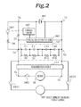
- Fig. 2 is a circuit diagram showing the configuration of a direct-current power source apparatus according to a second embodiment in which a diode D1 is disposed in parallel with the switching circuit SW1.
- component parts that are the same as those in the embodiment shown in Fig. 1 are denoted by reference numerals obtained by adding 100 to the reference numerals affixed to their counterparts in Fig. 1 to omit their descriptions.
- the diode D1 has an anode connected to the input/output portion T4 of a lithium-ion capacitor unit 101 and a cathode connected to the input/output portion T6 as a positive terminal of a secondary battery 103.
- a current from the secondary battery 103 is blocked by the diode D1 when the switching circuit SW1 is open (in a non-conductive state) . Therefore, only a direct-current power from the lithium-ion capacitor unit 101 is supplied to the motor M when the switching circuit SW1 is open.
- the presence of the diode D1 allows the direct-current charging power source 109 to charge the secondary battery 103 at the same time as charging the lithium-ion capacitor unit 101 at the standby station without separately providing a charger for the secondary battery 103.
- Fig. 3 is a circuit diagram showing the configuration of a direct-current power source apparatus according to a third embodiment of the present invention.
- the embodiment uses a unidirectional conductive device as the voltage detecting section and the changeover circuit.
- component parts that are the same as those in the embodiment shown in Fig. 1 are denoted by reference numerals obtained by adding 200 to the reference numerals affixed to their counterparts in Fig. 1 to omit their descriptions.
- a Zener diode ZD1 is used as a unidirectional conductive device which serves as the voltage detecting section and the changeover circuit. That is, the Zener diode ZD1 has an anode connected to the input/output portion T4 of a lithium-ion capacitor unit 201 and a cathode connected to the input/output portion T6 as a positive terminal of a secondary battery 203.
- the difference voltage between the voltage of the secondary battery 203 and the voltage of the lithium-ion capacitor unit 201 reaches a breakdown voltage (Zener voltage) because the motor M consumes electric charge of the lithium-ion capacitor unit 201
- an electric power is supplied through the conducted Zener diode ZD1 from the secondary battery 203 to the motor M.
- a charging current flows from the secondary battery 203 to the lithium-ion capacitor unit 201.
- the charging current is shut off when the difference voltage becomes lower than the Zener voltage.
- the automated guided vehicle preferably must return to the standby station at which the direct-current charging power source 209 is installed in order to charge the lithium-ion capacitor unit 201 as soon as possible, after supply of an electric power from the secondary battery 203 to the load is started.
- the embodiment it is possible to prevent the voltage of the lithium-ion capacitor unit from falling below the unit lower-limit voltage and to continue the supply of an electric power to the motor with a simple circuit without using a voltage detecting section that detects the voltage of the lithium-ion capacitor unit or a control circuit.
- Fig. 4 is a circuit diagram showing the configuration of a direct-current power source apparatus according to a fourth embodiment in which the changeover circuit is formed by a first discharging circuit and a second discharging circuit.
- component parts that are the same as those in the embodiment shown in Fig. 1 are denoted by reference numerals obtained by adding 300 to the reference numerals affixed to their counterparts in Fig. 1 to omit their descriptions.
- a lithium-ion capacitor unit 301 in the embodiment is formed by a module including four capacitor arrays connected in parallel with each other, each of the capacitor arrays including 16 lithium-ion capacitors C1 to C16 connected in series with each other (some of which are not shown in the drawing) .
- the capacitance of the lithium-ion capacitor unit 301 is 450 [F] (with each single cell having a capacitance of 1800 [F]). If the upper-limit voltage of each of the lithium-ion capacitors C1 to C16 is 3.8 [V], the voltage of the lithium-ion capacitor unit 301 is 60.8 [V]. The lower-limit voltage of the lithium-ion capacitors C1 to C16 is 2.2 [V] .
- the unit lower-limit voltage (V 1 ) is set to 40.0 [V] so that the voltage of the lithium-ion capacitor unit 301 does not fall below 35.2 [V] to prevent the system in the load from going down.
- Resistor elements (not shown in the drawing) are respectively connected in parallel with the lithium-ion capacitors C1 to C16. Each of the resistor elements forms a voltage equalizing circuit that equalizes the voltage of each of the lithium-ion capacitors C1 to C16.
- a resistor of 1 [k ⁇ ], for example, may be used as the resistor elements for voltage equalization.
- a valve-regulated lead-acid battery rated at 48.0 [V] (with 24 cells rated at 2 [V] connected in series) and 80 [Ah] is used as a secondary battery 303.
- a changeover circuit 308 is formed by a first discharging circuit 381 and a second discharging circuit 383.
- the first discharging circuit 381 is formed by a switch SW1 and a current limiting resistor 304 connected in series with the switch SW1.
- the second discharging circuit 383 is formed to include a switch SW3.
- the current limiting resistor 304 is provided for the purpose of preventing the secondary battery 303 from discharging an overcurrent when the switch SW1 becomes conductive.
- a motor drive circuit including an inverter circuit that operates in accordance with a control command is connected to a motor circuit MC including a motor serving as a load.
- the pair of terminals T3 and T4 of the lithium-ion capacitor unit 301 are respectively electrically connected to the pair of terminals T1 and T2 of the motor circuit MC.
- the terminal T1 of the motor circuit MC, the terminal T3 of the lithium-ion capacitor unit 301, and the terminal T5 of the secondary battery 303 are positive terminals.
- the terminal T2 of the motor circuit MC, the terminal T4 of the lithium-ion capacitor unit 301, and the terminal T6 of the secondary battery 303 are negative terminals commonly connected to a ground terminal of a charger 309.
- the first discharging circuit 381 is disposed between the positive terminal T3 of the lithium-ion capacitor unit 301 and the positive terminal T6 of the secondary battery 303.
- the second discharging circuit 383 is connected in parallel with the first discharging circuit 381.
- the lithium-ion capacitor unit 301 and the secondary battery 303 are connected in parallel with each other via the changeover circuit 308 including the first discharging circuit 381 and the second discharging circuit 383.
- the charger (direct-current charging power source) 309 is provided at a standby station for an automated guided vehicle. Each time the automated guided vehicle returns to the standby station, the terminals T1 and T2 are connected to output terminals T7 and T8 of the charger 309 to perform a charging operation. When the charger 309 and the direct-current power source apparatus of the automated guided vehicle are connected to each other, the charger 309 charges the lithium-ion capacitor unit 301 with a charging voltage that is slightly lower than the upper-limit voltage of the lithium-ion capacitor unit 301.
- a charging circuit 313 for the secondary battery 303 is connected between the terminal T1 and the terminal T5 of the secondary battery 303.
- the charging circuit 313 is formed by connecting a switch SW5 and a DC/DC converter 315 in series with each other.
- the switch SW5 gets into a conductive state in accordance with a conduction signal from a control circuit 307 with the charger 309 connected to the direct-current power source apparatus, charging of the secondary battery 303 is started. If the voltage detecting section 305 detects that the voltage of the secondary battery 303 has fallen down to or below a charging start voltage determined in advance, the control circuit 307 outputs a conduction signal for causing the switch SW5 to get into a conductive state when the charger 309 is connected to the direct-current power source apparatus. The switch SW5 is maintained in a conductive state while the on command is output.
- the DC/DC converter 315 applies to the secondary battery 303 a charging voltage obtained by decreasing a charging voltage of the lithium-ion capacitor unit 301 to a voltage suitable for charging the secondary battery 303. If the charging current from the DC/DC converter 315 is too high, the secondary battery 303 may be degraded. Therefore, the DC/DC converter 315 is configured to charge the secondary battery 303 with a current of about 1 to 7 [A], for example.
- the control circuit 307 stops outputting the on command to open the switch SW5, which completes charging. In the embodiment, the switch SW5 is opened except when the secondary battery 303 is charged, and thus a standby electric power is not consumed. Therefore, the lithium-ion capacitor unit 301 can be quickly charged without being affected by the charging state of the secondary battery 303.
- temperature detecting means 306 for detecting the ambient temperature of the secondary battery 303 is also provided.
- An output of the temperature detecting means 306 is input to a control section (not shown) of the DC/DC converter 315.
- the control section (not shown) adjusts the output voltage of the DC/DC converter 315 in accordance with the ambient temperature of the secondary battery 303 detected by the temperature detecting means 306. Specifically, the control section (not shown) adjusts the output voltage of the DC/DC converter 315 such that the charging voltage of the secondary battery 303 is decreased when the ambient temperature becomes higher, and increased when the ambient temperature becomes lower. This allows the secondary battery 303 to be charged with a charging voltage that is suitable for variations in ambient temperature, thereby alleviating a stress received by the secondary battery 303 due to overcharging or insufficient charging to extend the life of the secondary battery 303.
- the lithium-ion capacitor unit 301 supplies an electric power to the motor circuit MC while the charging voltage of the lithium-ion capacitor unit 301 is higher than the unit lower-limit voltage V 1 (40.0 [V]).
- both the switch SW1 and the switch SW3 in the changeover circuit 308 are opened. If the voltage detecting section 305 detects that a voltage V LIC between the terminals of the lithium-ion capacitor unit 301 has decreased to the unit lower-limit voltage V 1 (40.0 [V]) (step ST301), the control circuit 307 outputs a conduction signal for causing the switch SW1 to get into a conductive state (step ST302).
- the secondary battery 303 has been charged to a voltage that is higher than the voltage of the lithium-ion capacitor unit 301 which has decreased and the changeover circuit 308 takes a first circuit configuration. While the switch SW1 is in a conductive state, the secondary battery 303 supplies a drive current to the motor circuit MC and supplies a charging current to the lithium-ion capacitor unit 301 at the same time.
- the voltage of the secondary battery 303 at this time is 48.0 [V]
- the voltage difference between the voltage of the secondary battery 303 and the voltage of the lithium-ion capacitor unit 301, which has decreased to the unit lower-limit voltage V 1 (40.0 [V]) is 8.0 [V] .
- the internal resistance of the lithium-ion capacitor unit 301 is 10 [m ⁇ ] and the internal resistance of the secondary battery 303 is also 10 [m ⁇ ]
- the secondary battery 303 may discharge a maximum instantaneous current of as high as 400 [A] in the calculation.
- the secondary battery 3 charges the lithium-ion capacitor unit 301 via the first discharging circuit 381 including the current limiting resistor 304.
- the current limiting resistor 304 has a resistance of about 3.0 [ ⁇ ]/50 [W] to limit the discharging current to up to about 3 [A] if the voltage difference between the respective voltages of the secondary battery 303 and the lithium-ion capacitor unit 301 is 8.0 [V], for example.
- the control circuit 307 After the switch SW1 gets into a conductive state, if the voltage detecting section 305 detects that the voltage of the lithium-ion capacitor unit 301 has become a first set voltage V 2 (42.5 [V]) that is higher than the unit lower-limit voltage V 1 or a second set voltage V 3 (37.5 [V] ) that is lower than the unit lower-limit voltage V 1 (step ST303), the control circuit 307 outputs a conduction signal for causing the switch SW3 to get into a conductive state (step ST304).
- the changeover circuit 308 takes a second circuit configuration while the switch SW3 is in a conductive state.
- the switch SW1 may be opened after the switch SW3 is turned on.
- the first discharging circuit 381 is short-circuited by the second discharging circuit 383, and thereafter the current discharged from the secondary battery 303 is supplied from the second discharging circuit 383 to the motor circuit MC and the lithium-ion capacitor unit 301.
- the voltage of the lithium-ion capacitor unit 301 rises to the first set voltage V 2
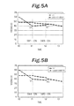
- a required electric power can be supplied to the motor circuit (load) MC using the secondary battery 303 without an overcurrent flowing through the motor circuit MC and the lithium-ion capacitor unit 301 can be charged by the secondary battery 303, after the changeover circuit 308 takes the first circuit configuration ( Fig. 5A ).
- the first set voltage V 2 is set to prohibit the current discharged from the secondary battery 303 to the load M from becoming an overcurrent.
- the current limiting resistor 304 fails to prevent the generation of overcurrent, but is merely cause for electric power loss.
- the changeover circuit 308 switches into the second circuit configuration to disconnect the current limiting resistor 304, thereby avoiding the generation of an electric power loss in the current limiting resistor 304 and alleviating the load on the secondary battery 303. As a result, this may retard deterioration of the capacity of the secondary battery 303.
- the first set voltage V 2 it is necessary to set the first set voltage V 2 such that the current discharged from the secondary battery 303 to the load when the changeover circuit 308 switches from the first circuit configuration into the second circuit configuration does not exceed the maximum discharging current.
- a fixed value may be used as the first set voltage V 2 as described above. In the case where a fixed value is used as the first set voltage V 2 , however, a current that is higher than the maximum discharging current may be discharged when the current limiting means in the first discharging circuit is short-circuited, if the rate of variations in voltage of the secondary battery 303 during discharging is high because of conditions such as degradation of the secondary battery 303, individual difference, and the ambient temperature.
- I ref 10 [A]
- R C 10 [m ⁇ ]
- R B 10 [m ⁇ ]
- the control circuit 307 stores the allowable difference voltage V dif calculated in advance using the formula (2), and the control circuit 307 determines the first set voltage V 2 on the basis of the formula (1). Then, if the voltage detecting section 5 detects that the voltage of the lithium-ion capacitor unit 301 has risen to the first set voltage V 2 , the control circuit 307 outputs a switching command to the changeover circuit 308.
- the formula (2) is determined for the following reasons. That is, in the case where the changeover circuit 308 takes the second circuit configuration, the lithium-ion capacitor unit 301 and the secondary battery 303 are directly connected to each other. At this time, the discharging circuit including the lithium-ion capacitor unit 301 and the secondary battery 303 includes only the internal resistance (R C ) of the lithium-ion capacitor unit 301 and the internal resistance (R B ) of the secondary battery 303 as resistance components.
- V d the allowable difference voltage V dif the value of a voltage obtained as the product [the formula (2) above] of the sum (R C + R B ) of the internal resistance of the lithium-ion capacitor unit 301 and the internal resistance of the secondary battery 303 and the maximum discharging current (I ref ) of the secondary battery 303, it is possible to minimize the electric power loss due to the current limiting resistance 304 while preventing degradation of the secondary battery 303.
- the changeover circuit 308 switches into the second circuit configuration (in which the switch SW3 is in a conductive state) to disconnect the current limiting resistor 304 from the discharging circuit, which allows the supply of a required electric power to the motor circuit (load) MC and prevents a decrease in voltage of the lithium-ion capacitor unit 301.
- the second set voltage V 3 is set to prohibit the voltage of each of the lithium-ion capacitors from falling down to the lower-limit voltage or less.
- a plurality of diodes connected in series with each other may be used in place of a DC/DC converter as means for decreasing the charging voltage.
- Fig. 7 shows the configuration of a direct-current power source apparatus according to a fifth embodiment of the present invention in which diodes are used in a charging circuit 413.
- component parts that are the same as those in the embodiment shown in Fig. 4 are denoted by reference numerals obtained by adding 100 to the reference numerals affixed to their counterparts in Fig. 4 to omit their descriptions.
- a plurality of diodes are connected in series with each other to form a diode array 417, which includes an anode connected to the terminal T3 of a lithium-ion capacitor unit 401 and a cathode connected to the positive terminal T5 of a secondary battery 403.
- the charging voltage of the secondary battery 403 can be easily adjusted by just determining the number of diodes in accordance with the rated voltage of the secondary battery 403 used without using a DC/DC converter.
- a lithium-ion capacitor unit can be fully utilized for the lithium-ion capacitor unit included in the electric storage system.
- the life of the lithium-ion capacitor unit can be extended.
- the supply of an electric power to a load can be continued even if the voltage of the lithium-ion capacitor unit has decreased.
- a burden on a secondary battery can be reduced to suppress degradation of the secondary battery and extend the life of the secondary battery.
- a direct-current power source apparatus capable of stably supplying an electric power can be provided.
Landscapes
- Engineering & Computer Science (AREA)
- Power Engineering (AREA)
- Mechanical Engineering (AREA)
- Transportation (AREA)
- Sustainable Energy (AREA)
- Sustainable Development (AREA)
- Life Sciences & Earth Sciences (AREA)
- Business, Economics & Management (AREA)
- Emergency Management (AREA)
- Chemical & Material Sciences (AREA)
- Combustion & Propulsion (AREA)
- General Engineering & Computer Science (AREA)
- Charge And Discharge Circuits For Batteries Or The Like (AREA)
- Secondary Cells (AREA)
- Electric Propulsion And Braking For Vehicles (AREA)
Applications Claiming Priority (3)
| Application Number | Priority Date | Filing Date | Title |
|---|---|---|---|
| JP2010061184A JP5488085B2 (ja) | 2010-03-17 | 2010-03-17 | 直流電源装置 |
| JP2011027574 | 2011-02-10 | ||
| JP2011029003A JP5664310B2 (ja) | 2011-02-10 | 2011-02-14 | 直流電源装置 |
Publications (2)
| Publication Number | Publication Date |
|---|---|
| EP2367261A2 true EP2367261A2 (fr) | 2011-09-21 |
| EP2367261A3 EP2367261A3 (fr) | 2014-09-10 |
Family
ID=44259600
Family Applications (1)
| Application Number | Title | Priority Date | Filing Date |
|---|---|---|---|
| EP20110158349 Withdrawn EP2367261A3 (fr) | 2010-03-17 | 2011-03-15 | Appareil de source d'alimentation à courant continu |
Country Status (5)
| Country | Link |
|---|---|
| US (1) | US8581557B2 (fr) |
| EP (1) | EP2367261A3 (fr) |
| KR (1) | KR20110104883A (fr) |
| CN (1) | CN102195333A (fr) |
| TW (1) | TW201218576A (fr) |
Cited By (4)
| Publication number | Priority date | Publication date | Assignee | Title |
|---|---|---|---|---|
| GB2568104A (en) * | 2017-11-07 | 2019-05-08 | Rotork Controls | Actuating mechanism with integral battery |
| CN111391676A (zh) * | 2020-03-20 | 2020-07-10 | 重庆中科超容科技有限公司 | 超级电容与电池并联控制系统 |
| US10897152B2 (en) | 2012-12-28 | 2021-01-19 | Semiconductor Energy Laboratory Co., Ltd. | Power storage device control system, power storage system, and electrical appliance |
| WO2021110276A1 (fr) * | 2019-12-05 | 2021-06-10 | Abb Schweiz Ag | Intégration de batteries et de supercondensateurs dans un système d'alimentation électrique de véhicule |
Families Citing this family (39)
| Publication number | Priority date | Publication date | Assignee | Title |
|---|---|---|---|---|
| JP5146487B2 (ja) * | 2010-05-24 | 2013-02-20 | トヨタ自動車株式会社 | 電源装置 |
| WO2013054795A1 (fr) * | 2011-10-11 | 2013-04-18 | Kachi Naoyoshi | Élément de stockage hybride, véhicule et unité de stockage de courant qui utilisent celui-ci, système de véhicules en réseau intelligent utilisant ce véhicule et système de réseau d'alimentation électrique utilisant l'unité de stockage de courant |
| US9421876B2 (en) | 2011-12-09 | 2016-08-23 | Honda Motor Co., Ltd. | Electric vehicle charging apparatus |
| US9577469B2 (en) * | 2011-12-16 | 2017-02-21 | Samsung Sdi Co., Ltd. | Battery pack |
| JP5953567B2 (ja) * | 2011-12-16 | 2016-07-20 | エリーパワー株式会社 | 蓄電装置およびその充放電方法 |
| CN104160586B (zh) | 2012-03-02 | 2017-12-05 | 日挥株式会社 | 电源装置、蓄电装置、及蓄电系统 |
| US9070950B2 (en) | 2012-03-26 | 2015-06-30 | Semiconductor Energy Laboratory Co., Ltd. | Power storage element, manufacturing method thereof, and power storage device |
| JP5677362B2 (ja) * | 2012-04-27 | 2015-02-25 | 本田技研工業株式会社 | 電源劣化判定装置 |
| JP5595450B2 (ja) * | 2012-07-02 | 2014-09-24 | 三菱電機株式会社 | 発電電動機の制御装置および発電電動機の制御方法 |
| DE102012211393A1 (de) * | 2012-07-02 | 2014-01-02 | Robert Bosch Gmbh | Batterie und Kraftfahrzeug |
| US9789769B2 (en) * | 2012-10-29 | 2017-10-17 | Sanyo Electric Co., Ltd. | Power supply device for vehicles |
| KR102246181B1 (ko) * | 2013-09-02 | 2021-04-29 | 에스케이이노베이션 주식회사 | 배터리 과충전 방지 장치 |
| JP5850017B2 (ja) | 2013-10-15 | 2016-02-03 | 株式会社デンソー | バッテリ監視装置 |
| CN106170904A (zh) * | 2014-03-03 | 2016-11-30 | 罗伯特·博世有限公司 | 混合存储系统 |
| CN104599850B (zh) * | 2014-12-30 | 2017-10-10 | 华为技术有限公司 | 一种充电方法及装置 |
| CN105667430B (zh) * | 2015-03-25 | 2018-11-23 | 深圳太研能源科技有限公司 | 一种启动控制装置、系统和方法 |
| JP6304500B2 (ja) * | 2015-07-31 | 2018-04-04 | 本田技研工業株式会社 | 車両用電源装置 |
| CN105634102B (zh) * | 2015-11-25 | 2018-11-02 | 上海展枭新能源科技有限公司 | 一种用于启动汽车的电源装置及其启动控制方法 |
| CN105599620B (zh) * | 2015-11-25 | 2018-01-02 | 上海展枭新能源科技有限公司 | 一种基于锂离子电容器的汽车启动电源装置及其启动控制方法 |
| AT517714B1 (de) * | 2015-12-17 | 2017-04-15 | Avl List Gmbh | Schaltungsanordnung zur Signaleinprägung eines elektrischen Signals in eine elektrochemische Energieliefervorrichtung |
| US10148223B2 (en) * | 2016-01-06 | 2018-12-04 | Nicholas Charles Herbert | Capacitor based automobile battery with backup LiFePo charging system and charging circuit |
| CN105871044B (zh) * | 2016-05-17 | 2018-08-10 | 上海展枭新能源科技有限公司 | 一种agv小车的电源装置及其控制方法 |
| CN106100046B (zh) * | 2016-07-14 | 2019-02-01 | 上海展枭新能源科技有限公司 | 一种agv小车的充电装置及其充电方法 |
| CN110234531B (zh) * | 2017-02-10 | 2022-08-26 | 本田技研工业株式会社 | 控制系统、移动体及控制方法 |
| JP6966864B2 (ja) * | 2017-04-20 | 2021-11-17 | エイブリック株式会社 | バッテリ装置 |
| JP7097622B2 (ja) * | 2017-05-10 | 2022-07-08 | 株式会社Wave Energy | 充放電回路、コンデンサユニット、及び、検電器 |
| CN109585867A (zh) * | 2017-09-28 | 2019-04-05 | 江苏津谊新能源科技有限公司 | 一种长日历寿命电池 |
| JPWO2019243950A1 (ja) | 2018-06-22 | 2021-07-26 | 株式会社半導体エネルギー研究所 | 蓄電装置の異常検知方法、及び蓄電装置の制御装置 |
| DE102018006582B4 (de) * | 2018-08-18 | 2024-08-22 | Stellantis Auto Sas | Batterie für ein Kraftfahrzeug und Kraftfahrzeugbordnetz |
| CN109372675B (zh) * | 2018-12-29 | 2024-10-18 | 神驰机电股份有限公司 | 电喷发动机控制系统 |
| US12263799B2 (en) * | 2019-06-26 | 2025-04-01 | Volvo Truck Corporation | Vehicle power supply system, vehicle comprising such system and method for recharging a vehicle battery |
| CN110816274A (zh) * | 2019-11-15 | 2020-02-21 | 珠海格力电器股份有限公司 | 一种供电控制装置、汽车及其供电控制方法 |
| CN111869930A (zh) * | 2020-06-30 | 2020-11-03 | 上海烟草集团有限责任公司 | 一种供电装置及气雾产生装置 |
| US20220166229A1 (en) * | 2020-11-24 | 2022-05-26 | Keith Bendle | Battery charging system and methods thereof |
| CN115250002A (zh) * | 2021-04-28 | 2022-10-28 | 天扬精密科技股份有限公司 | 智能能量存储系统 |
| KR102434036B1 (ko) * | 2021-06-17 | 2022-08-19 | 삼성전자주식회사 | 보조 전원 장치의 수명을 위한 충전 전압 제어 방법 및 이를 수행하는 스토리지 장치 |
| CN115333189B (zh) * | 2022-08-04 | 2025-03-11 | 杭州广迪科技有限公司 | 自发电水表电源管理系统和管理方法 |
| TWI844394B (zh) * | 2023-06-15 | 2024-06-01 | 宏碁股份有限公司 | 電池管理的電子裝置 |
| CN116788112B (zh) * | 2023-08-17 | 2023-12-05 | 广州巨湾技研有限公司 | 一种动力电池系统、电动汽车及动力电池系统控制方法 |
Citations (6)
| Publication number | Priority date | Publication date | Assignee | Title |
|---|---|---|---|---|
| JPH03104002A (ja) | 1989-09-18 | 1991-05-01 | Hitachi Ltd | 磁気記憶装置 |
| JPH06270695A (ja) | 1993-03-18 | 1994-09-27 | Aisin Aw Co Ltd | 電力供給装置 |
| JP3104002U (ja) | 2004-03-15 | 2004-08-26 | 孝夫 平野 | ペット用キャリーバッグ |
| JP2004266888A (ja) | 2003-02-17 | 2004-09-24 | Denso Corp | 自動車用電源装置 |
| JP2009112122A (ja) | 2007-10-30 | 2009-05-21 | Jm Energy Corp | 電力供給装置 |
| JP2010004587A (ja) | 2008-06-18 | 2010-01-07 | Meidensha Corp | 物流用搬送車の充電装置及び充電システム |
Family Cites Families (16)
| Publication number | Priority date | Publication date | Assignee | Title |
|---|---|---|---|---|
| US5652501A (en) * | 1994-12-12 | 1997-07-29 | Unitrode Corporation | Voltage sensor for detecting cell voltages |
| JP3549806B2 (ja) * | 2000-03-01 | 2004-08-04 | 株式会社日立製作所 | 自動車用電源の制御装置 |
| JP4006948B2 (ja) * | 2001-02-14 | 2007-11-14 | スズキ株式会社 | 車両用発電制御装置 |
| JP3896258B2 (ja) * | 2001-04-25 | 2007-03-22 | 株式会社日立製作所 | 自動車電源装置 |
| JP3872758B2 (ja) * | 2003-01-08 | 2007-01-24 | 株式会社日立製作所 | 電源制御装置 |
| EP2154028B8 (fr) | 2003-02-17 | 2015-12-09 | Denso Corporation | Système d'alimentation électrique de véhicule |
| TWI276240B (en) * | 2003-11-26 | 2007-03-11 | Ind Tech Res Inst | Fuel cell power supply device |
| DE102004062938A1 (de) * | 2004-12-28 | 2006-07-13 | Volkswagen Ag | Verfahren und Vorrichtung zum Betreiben eines Hybridenergiespeichers in einem Fahrzeug mit einem Hybridantriebsystem |
| JP2007020368A (ja) * | 2005-07-11 | 2007-01-25 | Komatsu Ltd | 蓄電素子の電圧均等化装置および方法 |
| JP2007066757A (ja) * | 2005-08-31 | 2007-03-15 | Canon Inc | ハイブリッド燃料電池 |
| AU2006304921B2 (en) * | 2005-10-19 | 2010-06-17 | The Raymond Corporation | Lift truck with hybrid power source |
| JP4804994B2 (ja) * | 2006-04-05 | 2011-11-02 | 株式会社小松製作所 | フォークリフト用電源装置 |
| WO2008144752A2 (fr) * | 2007-05-21 | 2008-11-27 | Nmhg Oregon, Llc | Recapture d'énergie pour un véhicule industriel |
| JP4828473B2 (ja) * | 2007-06-08 | 2011-11-30 | 富士重工業株式会社 | 車両用制御装置 |
| JP4561921B2 (ja) * | 2008-04-04 | 2010-10-13 | 株式会社デンソー | 電圧検出装置、及び電池の状態制御装置 |
| JP5221468B2 (ja) * | 2009-02-27 | 2013-06-26 | 株式会社日立製作所 | 電池監視装置 |
-
2011
- 2011-03-07 KR KR1020110019984A patent/KR20110104883A/ko not_active Ceased
- 2011-03-07 CN CN2011100537179A patent/CN102195333A/zh active Pending
- 2011-03-15 TW TW100108705A patent/TW201218576A/zh unknown
- 2011-03-15 US US13/048,267 patent/US8581557B2/en not_active Expired - Fee Related
- 2011-03-15 EP EP20110158349 patent/EP2367261A3/fr not_active Withdrawn
Patent Citations (6)
| Publication number | Priority date | Publication date | Assignee | Title |
|---|---|---|---|---|
| JPH03104002A (ja) | 1989-09-18 | 1991-05-01 | Hitachi Ltd | 磁気記憶装置 |
| JPH06270695A (ja) | 1993-03-18 | 1994-09-27 | Aisin Aw Co Ltd | 電力供給装置 |
| JP2004266888A (ja) | 2003-02-17 | 2004-09-24 | Denso Corp | 自動車用電源装置 |
| JP3104002U (ja) | 2004-03-15 | 2004-08-26 | 孝夫 平野 | ペット用キャリーバッグ |
| JP2009112122A (ja) | 2007-10-30 | 2009-05-21 | Jm Energy Corp | 電力供給装置 |
| JP2010004587A (ja) | 2008-06-18 | 2010-01-07 | Meidensha Corp | 物流用搬送車の充電装置及び充電システム |
Cited By (7)
| Publication number | Priority date | Publication date | Assignee | Title |
|---|---|---|---|---|
| US10897152B2 (en) | 2012-12-28 | 2021-01-19 | Semiconductor Energy Laboratory Co., Ltd. | Power storage device control system, power storage system, and electrical appliance |
| US12034327B2 (en) | 2012-12-28 | 2024-07-09 | Semiconductor Energy Laboratory Co., Ltd. | Power storage device control system, power storage system, and electrical appliance |
| GB2568104A (en) * | 2017-11-07 | 2019-05-08 | Rotork Controls | Actuating mechanism with integral battery |
| US11742676B2 (en) | 2017-11-07 | 2023-08-29 | Rotork Controls Limited | Actuating mechanism with integral battery |
| WO2021110276A1 (fr) * | 2019-12-05 | 2021-06-10 | Abb Schweiz Ag | Intégration de batteries et de supercondensateurs dans un système d'alimentation électrique de véhicule |
| US20220416564A1 (en) * | 2019-12-05 | 2022-12-29 | Abb Schweiz Ag | Integration Of Batteries and Super-Capacitors In A Vehicular Power Supply System |
| CN111391676A (zh) * | 2020-03-20 | 2020-07-10 | 重庆中科超容科技有限公司 | 超级电容与电池并联控制系统 |
Also Published As
| Publication number | Publication date |
|---|---|
| CN102195333A (zh) | 2011-09-21 |
| TW201218576A (en) | 2012-05-01 |
| KR20110104883A (ko) | 2011-09-23 |
| EP2367261A3 (fr) | 2014-09-10 |
| US20110227540A1 (en) | 2011-09-22 |
| US8581557B2 (en) | 2013-11-12 |
Similar Documents
| Publication | Publication Date | Title |
|---|---|---|
| US8581557B2 (en) | Direct-current power source apparatus | |
| US9444285B2 (en) | Charge controller for vehicle | |
| US12074465B2 (en) | Control device, electric storage device, electric storage system, and computer-readable medium | |
| JP6445190B2 (ja) | 電池制御装置 | |
| TWI474577B (zh) | 電池管理系統、電池模組及均衡多個電池模組的方法 | |
| CN103795104B (zh) | 蓄电系统以及电源系统 | |
| KR102392376B1 (ko) | 배터리 시스템 | |
| JP6814437B2 (ja) | 制御装置、バランス補正装置、蓄電システム、及び、装置 | |
| JP7496134B2 (ja) | 蓄電システム | |
| US9853465B2 (en) | Connecting electrical storage devices in parallel | |
| EP2372865A2 (fr) | Dispositif d'alimentation capable d'égaliser les propriétés électriques de batteries | |
| US9979212B2 (en) | Device and method for charge equalization of an energy accumulator arrangement | |
| US11552483B2 (en) | Electric storage system | |
| KR20160099357A (ko) | 배터리 팩 및 이를 포함하는 배터리 시스템 | |
| JP7620325B2 (ja) | 蓄電システム | |
| JP2020102916A (ja) | 電力供給システムおよび電力供給方法 | |
| JP5664310B2 (ja) | 直流電源装置 | |
| JP6214131B2 (ja) | 組電池充電システムおよび組電池充電方法 | |
| JP5488085B2 (ja) | 直流電源装置 | |
| KR20190071459A (ko) | 배터리 충전 시스템 및 이를 이용한 배터리 모듈의 최대용량 충전 제어방법 | |
| JP2011182479A (ja) | リチウムイオン組電池の充電システムおよび充電方法 | |
| JP7557856B2 (ja) | 方法、定格電圧調整装置、及び、蓄電装置 | |
| CN112913107A (zh) | 蓄电系统以及充电控制方法 | |
| JP2004288537A (ja) | パック電池、二次電池充電装置および二次電池充電方法 | |
| JP2010252552A (ja) | 放電器、放電方法および直流電源システム |
Legal Events
| Date | Code | Title | Description |
|---|---|---|---|
| PUAI | Public reference made under article 153(3) epc to a published international application that has entered the european phase |
Free format text: ORIGINAL CODE: 0009012 |
|
| AK | Designated contracting states |
Kind code of ref document: A2 Designated state(s): AL AT BE BG CH CY CZ DE DK EE ES FI FR GB GR HR HU IE IS IT LI LT LU LV MC MK MT NL NO PL PT RO RS SE SI SK SM TR |
|
| AX | Request for extension of the european patent |
Extension state: BA ME |
|
| PUAL | Search report despatched |
Free format text: ORIGINAL CODE: 0009013 |
|
| AK | Designated contracting states |
Kind code of ref document: A3 Designated state(s): AL AT BE BG CH CY CZ DE DK EE ES FI FR GB GR HR HU IE IS IT LI LT LU LV MC MK MT NL NO PL PT RO RS SE SI SK SM TR |
|
| AX | Request for extension of the european patent |
Extension state: BA ME |
|
| RIC1 | Information provided on ipc code assigned before grant |
Ipc: H02J 9/02 20060101ALI20140807BHEP Ipc: H02J 7/34 20060101AFI20140807BHEP Ipc: B60L 11/12 20060101ALI20140807BHEP Ipc: B60L 11/00 20060101ALI20140807BHEP Ipc: B60R 16/033 20060101ALI20140807BHEP Ipc: F02N 11/08 20060101ALI20140807BHEP Ipc: H02J 7/00 20060101ALI20140807BHEP Ipc: B60L 1/00 20060101ALI20140807BHEP Ipc: H02J 7/04 20060101ALI20140807BHEP |
|
| STAA | Information on the status of an ep patent application or granted ep patent |
Free format text: STATUS: THE APPLICATION IS DEEMED TO BE WITHDRAWN |
|
| 18D | Application deemed to be withdrawn |
Effective date: 20150311 |