EP2367352A2 - Bildaufnahmegerät und Verfahren - Google Patents
Bildaufnahmegerät und Verfahren Download PDFInfo
- Publication number
- EP2367352A2 EP2367352A2 EP11151665A EP11151665A EP2367352A2 EP 2367352 A2 EP2367352 A2 EP 2367352A2 EP 11151665 A EP11151665 A EP 11151665A EP 11151665 A EP11151665 A EP 11151665A EP 2367352 A2 EP2367352 A2 EP 2367352A2
- Authority
- EP
- European Patent Office
- Prior art keywords
- distance
- inverse
- image
- inverse function
- obtained image
- Prior art date
- Legal status (The legal status is an assumption and is not a legal conclusion. Google has not performed a legal analysis and makes no representation as to the accuracy of the status listed.)
- Granted
Links
Images


Classifications
-
- H—ELECTRICITY
- H04—ELECTRIC COMMUNICATION TECHNIQUE
- H04N—PICTORIAL COMMUNICATION, e.g. TELEVISION
- H04N23/00—Cameras or camera modules comprising electronic image sensors; Control thereof
- H04N23/50—Constructional details
- H04N23/55—Optical parts specially adapted for electronic image sensors; Mounting thereof
-
- G—PHYSICS
- G01—MEASURING; TESTING
- G01C—MEASURING DISTANCES, LEVELS OR BEARINGS; SURVEYING; NAVIGATION; GYROSCOPIC INSTRUMENTS; PHOTOGRAMMETRY OR VIDEOGRAMMETRY
- G01C3/00—Measuring distances in line of sight; Optical rangefinders
- G01C3/02—Details
- G01C3/06—Use of electric means to obtain final indication
- G01C3/08—Use of electric radiation detectors
-
- G—PHYSICS
- G01—MEASURING; TESTING
- G01S—RADIO DIRECTION-FINDING; RADIO NAVIGATION; DETERMINING DISTANCE OR VELOCITY BY USE OF RADIO WAVES; LOCATING OR PRESENCE-DETECTING BY USE OF THE REFLECTION OR RERADIATION OF RADIO WAVES; ANALOGOUS ARRANGEMENTS USING OTHER WAVES
- G01S11/00—Systems for determining distance or velocity not using reflection or reradiation
- G01S11/12—Systems for determining distance or velocity not using reflection or reradiation using electromagnetic waves other than radio waves
-
- G—PHYSICS
- G06—COMPUTING OR CALCULATING; COUNTING
- G06T—IMAGE DATA PROCESSING OR GENERATION, IN GENERAL
- G06T5/00—Image enhancement or restoration
- G06T5/73—Deblurring; Sharpening
-
- G—PHYSICS
- G06—COMPUTING OR CALCULATING; COUNTING
- G06T—IMAGE DATA PROCESSING OR GENERATION, IN GENERAL
- G06T7/00—Image analysis
- G06T7/50—Depth or shape recovery
- G06T7/529—Depth or shape recovery from texture
Definitions
- Example embodiments relate to an imaging apparatus, an imaging method and a computer-readable medium that may photograph an object to obtain an image, and more particularly, to an imaging apparatus, an imaging method and a computer-readable medium that may adjust a location of a camera unit to be the same as a location of a display unit to provide an accurate face-to-face video service in an apparatus including both a display unit and a camera unit.
- An interface device may not provide an accurate face-to-face video service, since a location of a camera may be different from a location of a display.
- a video call service may include a representative example of the difficulties that may occur.
- a terminal providing the video call service may include, in an upper side of a display, a camera obtaining an image to provide the video call service. Accordingly, when the video call service is performed, an appearance of the user may be provided, to another party, as if the user half-closes his/her eyes and the video call service may not be able to accurately show the appearance of the user. This phenomenon may get worse as the user who is using the video call gets closer to the display.
- Another case where difficulties may occur is where the location of the camera is different from the location of the display, such as in a video conference.
- the video conference that enables a user to feel as though the user is in the same place with another party who is far from the user using a large screen, may transmit an inaccurately captured front image of the user to the other party when the user is close to the screen.
- a gesture close to the display may not be sensed.
- an imaging apparatus may include a camera unit to photograph an object through at least one aperture of a pixel of a display panel, a distance measurement table to store a disparity distance generated by a blur effect generated based on zoom information of the camera unit and a distance to the object, and a distance measurement unit to determine zoom information of an image obtained through photographing the object by the camera and a disparity distance of the obtained image, and to measure the distance to the object included in the obtained image.
- the disparity distance may be a distance between a sharpest edge in the obtained image and a second sharpest edge generated by the blur effect.
- the distance measurement unit may measure the distance to the object for each area having the same disparity distance in the obtained image.
- the imaging apparatus may further include an inverse function table to store inverse functions removing the blur effects, the inverse functions respectively corresponding to point spread functions generated based on the distance to the object, and an image enhancement unit to search for an inverse function corresponding to the measured distance to the object from the inverse function table, and to enhance the obtained image by applying the retrieved inverse function to the obtained image to remove the blur effect.
- an inverse function table to store inverse functions removing the blur effects, the inverse functions respectively corresponding to point spread functions generated based on the distance to the object
- an image enhancement unit to search for an inverse function corresponding to the measured distance to the object from the inverse function table, and to enhance the obtained image by applying the retrieved inverse function to the obtained image to remove the blur effect.
- the image enhancement unit may search for an inverse function corresponding to the measured distance for each area, and apply, to the obtained image, the inverse function retrieved for each area to remove the blur effect.
- an imaging apparatus may include a camera unit to photograph an object through at least one aperture of a pixel of a display panel, an inverse function table to store inverse functions that remove blur effects, the inverse functions respectively corresponding to point spread functions generated based on a distance to the object, an inverse function applying unit to apply each of the inverse functions to an image obtained through photographing by a camera, a focus extractor to extract, for each image where the inverse function is applied, a focus area where the camera accurately focuses on, and an image enhancement unit to replace all areas of the obtained image with the focus areas of the images where the inverse functions are respectively applied.
- the apparatus may further include a distance measurement unit to determine an inverse function that is applied for each substituted focus area, to determine a distance to the object corresponding to the inverse function based on the inverse function table to measure the distance to the object for each focus area.
- a distance measurement unit to determine an inverse function that is applied for each substituted focus area, to determine a distance to the object corresponding to the inverse function based on the inverse function table to measure the distance to the object for each focus area.
- an imaging apparatus may include a camera unit to photograph an object through at least one aperture of a pixel of a display panel, a distance measurement unit to measure a distance to the object included in an image obtained through photographing by a camera, an inverse function table to store inverse functions that remove blur effects, the inverse functions respectively corresponding to point spread functions generated based on the distance to the object, and an image enhancement unit to search for an inverse function corresponding to the measured distance to the object from the inverse function table, and to apply the retrieved inverse function to the obtained image to remove a blur effect.
- the distance measurement unit may measure the distance to the object based on a wavelength value corresponding to a color of the object.
- the distance measurement unit may measure the distance to the object based on a wavelength value of the infrared ray.
- the method may include generating, by a processor, an image obtained by photographing through at least one aperture of a pixel of a display panel, determining, by the processor, zoom information associated with the obtained image and a disparity distance of the obtained image, and measuring, by the processor, a distance to the object included in the obtained image using a distance measurement table storing the disparity distance generated by a blur effect generated based on the zoom information and the distance to the object.
- the disparity distance may be a distance between a sharpest edge in the obtained image and a second sharpest edge generated by the blur effect.
- the method may further include searching for an inverse function corresponding to the measured distance to the object from the inverse function table storing inverse functions that remove blur effects, the inverse functions respectively corresponding to point spread functions generated based on the distance to the object, and enhancing the obtained image by applying the retrieved inverse function to the obtained image to remove the blur effect.
- the measuring may measure the distance to the object for each area having the same disparity distance in the obtained image.
- the method may further include searching for an inverse function corresponding to the measured distance for each area in the obtained image from the inverse function table storing inverse functions that remove the blur effects, the inverse functions respectively corresponding to the point spread functions generated based on the distance to the object, and enhancing the obtained image by applying, to the obtained image, the inverse function retrieved for each area to remove the blur effect.
- the method may include generating, by a processor, an image obtained by photographing through at least one aperture of a pixel of a display panel, applying by the processor, to the obtained image, each of inverse functions that remove blur effects, the inverse functions respectively corresponding to point spread functions generated based on a distance to an object, extracting, by the processor, a focus area that a camera appropriately focuses on for each image where the inverse function is applied, and enhancing, by the processor, the obtained image by replacing all areas of the obtained area with the focus areas of images where the inverse functions are respectively applied.
- the method may further include determining an inverse function that is applied for each substituted focus area, and determining a distance to the object corresponding to the inverse function to measure a distance to the object for each focus area.
- the method may include generating, by a processor, an image obtained by photographing through at least one aperture of a pixel of a display panel, measuring, by the processor, a distance to an object included in the obtained image, searching, by a processor, for an inverse function corresponding to the measured distance to the object from the inverse function table storing inverse functions that remove blur effects, the inverse functions respectively corresponding to point spread functions generated based on the distance to the object, and enhancing, by the processor, the obtained image by applying the retrieved inverse function to the obtained image to remove a blur effect.
- the measuring may measure the distance to the object based on a wavelength value corresponding to a color of the object or a wavelength value of an infrared ray used as an external light source.
- the measuring may measure the distance to the object based on a wavelength value of the infrared ray.
- At least one computer readable medium including computer readable instructions that control at least one processor to implement methods of one or more embodiments.
- An imaging apparatus and an imaging method may utilize a camera unit located in back of a display panel to photograph an object through at least one aperture of each pixel of a display panel, may adjust a location of the camera unit to be the same as a location of a display unit, may measure a distance to the object using a blur effect occurring when photographing through the at least one aperture of the display panel, and may enhance an image where the blur effect is included.
- the camera unit may be located in back of the display panel, such as a liquid crystal display (LCD) panel and an organic light emitting diodes (OLED) panel, and the display panel may structurally include at least one aperture.
- the camera unit may photograph the object through the at least one aperture of the display panel, and the image obtained by photographing may include a different blur effect based on a size of the at least one aperture, as illustrated in FIG. 1 .
- a blur may be classified into a blur due to a geometric effect and a blur due to a diffraction effect.
- Equation 1 The blur due to the geometric effect may be expressed by Equation 1.
- B G a ⁇ d o + d i / d o
- Equation 1 B G denotes the blur due to the geometric effect, a denotes a diameter of an aperture, d o denotes a distance between the aperture and the object, and d i denotes a distance between the aperture and an image sensor.
- the blur due to the diffraction effect may be expressed according to a wavelength ( ⁇ ) of light as given in Equation 2.
- B D 2.44 ⁇ d i / a
- Equation 2 B D denotes a blur due to the diffraction effect, ⁇ denotes a wavelength of a light, a denotes a size of the aperture, and d i denotes a distance between the aperture and the image sensor.
- a size of a total blur may be expressed by a sum of the two effects, as given in Equation 3.
- Equation 3 B denotes the size of the total blur, B G denotes a blur due to the geometric effect, B D denotes a blur due to the diffraction effect, a denotes the size of the aperture, ⁇ denotes a wavelength of a light, d o denotes the distance between the aperture and the object, and d i denotes the distance between the aperture and the image sensor.
- FIG. 1 illustrates an image obtained by photographing an object through at least one aperture of a display panel based on at least one aperture ratio. Referring to FIG. 1 , when a size of the at least one aperture is smaller, a diffraction is larger.
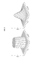
- the blur effect that occurs when the object is photographed through the at least one aperture of the display panel may be different responsive to a distance between the object and the at least one aperture and a distance between the at least one aperture and an image sensor, in addition to a size of the at least one aperture, as illustrated in FIG. 2 .
- FIG. 2 illustrates an image obtained by photographing through at least one aperture based on a distance to an object.
- a disparity distance of the image which is generated due to a blur effect may increase responsive to the distance to the object.
- the disparity distance generated due to the blur effect may be a distance between a sharpest edge in the obtained image and a second sharpest edge generated by the blur effect.
- the disparity distance when the distance to the object is one meter, the disparity distance may be about 10 pixels. When the distance to the object is two meters, the disparity distance may be about 18 pixels. When the distance to the object is three meters, the disparity distance may be about 25 pixels.
- FIG. 3 illustrates an example of a point spread function generated when an object is photographed through at least one aperture of a display panel.
- Pillbox Function is a point spread function indicating a blur due to a geometric effect and Gaussian is a point spread function indicating a blur further including a diffraction effect.
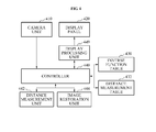
- FIG. 4 illustrates an example of an imaging apparatus that photographs an object through at least one aperture of each pixel of a display panel.
- the imaging apparatus may include a camera unit 410, a display panel 420, an inverse function table 430, a distance measurement table 432, a controller 440, a distance measurement unit 442, an image enhancement unit 444, and a display processing unit 449.
- the display panel 420 may be a panel, such as a liquid crystal display (LCD) panel and an organic light emitting diode (OLED) panel, including pixels structurally including apertures.
- LCD liquid crystal display
- OLED organic light emitting diode
- the display processing unit 449 may control the display panel 420 and may output an image through the display panel 420.
- the camera unit 410 may be located in back of the display panel 420 and may obtain the image of the object through at least one aperture of each of the pixels of the display panel 420.
- the camera unit 410 may be configured by only an image sensor.
- the inverse function table 430 may store inverse functions of point spread functions that remove blur effects, the inverse functions respectively corresponding to point spread functions generated based on a distance to the object.
- the distance measurement table 432 may store a distance to the photographed object corresponding to a disparity distance generated by zoom information associated with a zoom level of a camera unit and a blur effect.
- the zoom information may be a standard to indicate a level of zoom used for photographing.
- the distance measurement table 432 may be as given in Table 1.
- the distance measurement unit 442 may determine zoom information of the obtained image and a disparity distance of the obtained image, and may measure the distance to the object included in the obtained image using the distance measurement table 432.
- the distance measurement unit 442 may measure the distance to the object based on an interpolation scheme using approximate disparity distances included in the distance measurement table 432.
- the disparity distance may be a distance between a sharpest edge of the object in the obtained image and a second sharpest edge generated by a blur effect.
- the distance measurement unit 442 may measure the distance to the object for each area having the same disparity distance in the obtained image.
- the distance measurement unit 442 may measure the distance to the object using various methods. When a size of the blur is determined, the distance to the object may be measured based on a wavelength value corresponding to a color of the object or based on a wavelength value corresponding to an infrared ray used as a separate light source.
- d o a 2 ⁇ d l / aB - 2.44 ⁇ d l - a 2
- Equation 4 d o denotes a distance between an aperture and the object, a denotes a size of the aperture, d i denotes a distance between the aperture and an image sensor, B denotes a size of a total blur, the size being a sum of a blur due to a geometric effect and a blur due to a diffraction effect, and ⁇ denotes a wavelength value corresponding to a color of an area where the distance is measured.
- the image enhancement unit 444 may search for an inverse function corresponding to the measured distance to the object from the inverse function table 430, may apply the retrieved inverse function to the obtained image to remove the blur effect, and may enhance the image.
- the obtained image including the blur effect may be expressed by Equation 5.
- I ⁇ x ⁇ y I x ⁇ y * H x ⁇ y
- I'(x, y) denotes the obtained image including the blur effect
- I(x, y) denotes an original image where the blur effect is not included
- H(x, y) denotes a point spread function.
- Equation 6 I(x, y) denotes the original image where the blur effect is removed, I'(x, y) denotes the obtained image including the blur effect, and H -1 (x, y) denotes an inverse function of the point spread function.
- the image enhancement unit 444 may search for an inverse function corresponding to the measured distance for each area of the obtained image, from the inverse function table 430, may apply the retrieved inverse function to the obtained image to remove the blur effect, and may enhance the image.
- the controller 440 may generally control the imaging apparatus, and may perform a function of the distance measurement unit 442, a function of the image enhancement unit 444, and a function of the display processing unit 449.
- the described elements are separately illustrated to separately describe each function. Accordingly, when a product is actually embodied, the controller 440 may be configured to perform all functions of the elements or may be configured to perform several functions of the elements.
- FIG. 5 illustrates example embodiments, including another example of an imaging apparatus that may photograph an object through at least one aperture of each pixel of a display panel.
- the imaging apparatus may include a camera unit 510, a display panel 520, an inverse function table 530, a controller 540, an inverse function applying unit 542, a focus extractor 544, an image enhancement unit 546, a distance measurement unit 548, and a display processing unit 549.
- the display panel 520 may be a panel, such as an LCD panel and an OLED panel, including pixels structurally including apertures.
- the display processing unit 549 may control the display panel 520 and output an image through the display panel 520.
- the camera unit 510 may be located in back of the display panel 520 and may obtain the image of the object through the at least one aperture of each of the pixels of the display panel 520.
- the camera unit 510 may be configured by only an image sensor.
- the inverse function table 530 may store inverse functions of point spread functions that remove blur effects, the inverse functions respectively corresponding to the point spread functions generated based on a distance to the object.
- the inverse function applying unit 542 may apply, to the obtained image, each of the inverse functions included in the inverse function table 530.
- the focus extractor 544 may extract a focus area that the camera accurately focuses on from each image where an inverse function is applied.
- the image enhancement unit 546 may replace all areas of the obtained image with focus areas of images where the inverse functions are respectively applied to remove the blur effect, and may enhance the image.
- the distance measurement unit 548 may determine an inverse function for each substituted focus area, and may determine a distance to the object, the distance corresponding to the inverse function, to measure the distance to the object for each focus area.
- the controller 540 may generally control the imaging apparatus, and may perform a function of the inverse function applying unit 542, a focus extractor 544, an image enhancement unit 546, a distance measurement unit 548, and a display processing unit 549.
- the described elements are separately illustrated to separately describe each function. Accordingly, when a product is actually embodied, the controller 540 may be configured to perform all functions of the elements or may be configured to perform several functions of the elements.
- FIG. 6 illustrates example embodiments including an example of an imaging method that photographs an object through at least one aperture of each pixel of a display panel.
- an imaging apparatus may obtain an image of the object through at least one aperture of a pixel in back of the display panel in operation 610.
- the imaging apparatus measures a distance to the object included in the obtained image using a blur effect in operation 612.
- zoom information and a disparity distance of the obtained image are determined, and the distance to the object included in the obtained image may be measured using a distance measurement table.
- the distance to the object may be measured for each area having the same disparity distance in the obtained image.
- the distance measurement unit 442 may measure the distance based on Equation 4.
- the imaging apparatus may search for an inverse function corresponding to the measured distance to the object from an inverse function table storing inverse functions that remove blur effects, the inverse functions respectively corresponding to point spread functions generated based on the distance to the object in operation 614, may apply the retrieved inverse function to the obtained image to remove the blur effect, and may enhance the image.
- FIG. 7 illustrates example embodiments including another example of an imaging method including photographing an object through at least one aperture of each pixel of a display panel.
- the imaging apparatus obtains an image of the object through at least one aperture of a pixel in back of the display panel in operation 710.
- the imaging apparatus applies, to the obtained image, each of inverse functions that remove blur effects, the inverse functions respectively corresponding to point spread functions generated based on a distance to the object.
- the imaging apparatus extracts a focus area for each image that a camera accurately focuses on, and applies the inverse functions.
- the imaging apparatus replaces all areas of the obtained image with focus areas of the images where the inverse functions are respectively applied to enhance the image.
- the imaging apparatus determines an inverse function applied for each focus area to determine the distance to the object corresponding to the inverse function, and may measure the distance to the object for each focus area.
- an imaging apparatus that photographs an object through at least one aperture of each pixel of a display panel.
- a camera unit is located in back of the display panel and may accurately photograph a front of a face of a user when providing a face-to-face video service, such as a video call.
- a distance to the object may be measured using a blur effect.
- the above-described embodiments may be recorded in non-transitory computer-readable media including program instructions to implement various operations embodied by a computer.
- the media may also include, alone or in combination with the program instructions, data files, data structures, and the like.
- Examples of computer-readable media include magnetic media such as hard disks, floppy disks, and magnetic tape; optical media such as CD ROM disks and DVDs; magneto-optical media such as optical disks; and hardware devices that are specially configured to store and perform program instructions, such as read-only memory (ROM), random access memory (RAM), flash memory, and the like.
- the computer-readable media may be a plurality of computer-readable storage devices in a distributed network, so that the program instructions are stored in the plurality of computer-readable storage devices and executed in a distributed fashion.
- the program instructions may be executed by one or more processors or processing devices.
- the computer-readable media may also be embodied in at least one application specific integrated circuit (ASIC) or Field Programmable Gate Array (FPGA). Examples of program instructions include both machine code, such as produced by a compiler, and files containing higher level code that may be executed by the computer using an interpreter.
- the described hardware devices may be configured to act as one or more software modules in order to perform the operations of the above-described exemplary embodiments, or vice versa.
Landscapes
- Physics & Mathematics (AREA)
- Engineering & Computer Science (AREA)
- General Physics & Mathematics (AREA)
- Theoretical Computer Science (AREA)
- Electromagnetism (AREA)
- Radar, Positioning & Navigation (AREA)
- Remote Sensing (AREA)
- Computer Vision & Pattern Recognition (AREA)
- Multimedia (AREA)
- Signal Processing (AREA)
- Studio Devices (AREA)
Applications Claiming Priority (1)
| Application Number | Priority Date | Filing Date | Title |
|---|---|---|---|
| KR1020100022696A KR101640456B1 (ko) | 2010-03-15 | 2010-03-15 | 디스플레이 패널의 각 픽셀들의 개구부를 통해 촬영하는 촬영 장치 및 방법 |
Publications (3)
| Publication Number | Publication Date |
|---|---|
| EP2367352A2 true EP2367352A2 (de) | 2011-09-21 |
| EP2367352A3 EP2367352A3 (de) | 2014-02-19 |
| EP2367352B1 EP2367352B1 (de) | 2019-10-23 |
Family
ID=43533359
Family Applications (1)
| Application Number | Title | Priority Date | Filing Date |
|---|---|---|---|
| EP11151665.4A Active EP2367352B1 (de) | 2010-03-15 | 2011-01-21 | Bildaufnahmegerät und Verfahren |
Country Status (3)
| Country | Link |
|---|---|
| US (1) | US9100563B2 (de) |
| EP (1) | EP2367352B1 (de) |
| KR (1) | KR101640456B1 (de) |
Families Citing this family (15)
| Publication number | Priority date | Publication date | Assignee | Title |
|---|---|---|---|---|
| US8355039B2 (en) * | 2010-07-06 | 2013-01-15 | DigitalOptics Corporation Europe Limited | Scene background blurring including range measurement |
| KR101248225B1 (ko) * | 2012-10-31 | 2013-03-27 | (주)나인정보시스템 | 팬, 틸트, 줌 기능을 갖는 돔 카메라에서의 영상 디블러링 방법 |
| KR102140134B1 (ko) | 2013-09-25 | 2020-07-31 | 삼성전자주식회사 | 전자장치의 화면 표시장치 및 방법 |
| CN108737773A (zh) * | 2017-04-21 | 2018-11-02 | 路志宏 | 一种工程智能视觉检测设备 |
| JP7468523B2 (ja) * | 2019-06-05 | 2024-04-16 | ソニーグループ株式会社 | 移動体、位置推定方法、およびプログラム |
| US11575865B2 (en) | 2019-07-26 | 2023-02-07 | Samsung Electronics Co., Ltd. | Processing images captured by a camera behind a display |
| US11721001B2 (en) * | 2021-02-16 | 2023-08-08 | Samsung Electronics Co., Ltd. | Multiple point spread function based image reconstruction for a camera behind a display |
| US11722796B2 (en) | 2021-02-26 | 2023-08-08 | Samsung Electronics Co., Ltd. | Self-regularizing inverse filter for image deblurring |
| KR20220161595A (ko) | 2021-05-27 | 2022-12-07 | 삼성디스플레이 주식회사 | 전자 장치 및 그 구동 방법 |
| US12393765B2 (en) | 2021-08-06 | 2025-08-19 | Samsung Electronics Co., Ltd. | Automating search for improved display structure for under-display camera systems |
| US12216277B2 (en) | 2021-10-14 | 2025-02-04 | Samsung Electronics Co., Ltd. | Optical element for deconvolution |
| JP7686531B2 (ja) * | 2021-10-27 | 2025-06-02 | 株式会社東芝 | 測距装置、処理装置、方法及びプログラム |
| JP7693516B2 (ja) | 2021-11-08 | 2025-06-17 | 株式会社東芝 | 画像処理装置、方法及びプログラム |
| US12482075B2 (en) | 2022-06-08 | 2025-11-25 | Samsung Electronics Co., Ltd. | Restoring images using deconvolution |
| US20240169497A1 (en) * | 2022-11-23 | 2024-05-23 | Samsung Electronics Co., Ltd. | Airy-Disk Correction for Deblurring an Image |
Family Cites Families (13)
| Publication number | Priority date | Publication date | Assignee | Title |
|---|---|---|---|---|
| JP4004117B2 (ja) * | 1997-10-17 | 2007-11-07 | オリンパス株式会社 | 撮像装置 |
| US6775014B2 (en) * | 2001-01-17 | 2004-08-10 | Fujixerox Co., Ltd. | System and method for determining the location of a target in a room or small area |
| WO2004063989A2 (en) * | 2003-01-16 | 2004-07-29 | D-Blur Technologies Ltd. | Camera with image enhancement functions |
| JP4529366B2 (ja) | 2003-03-26 | 2010-08-25 | 株式会社ニコン | 欠陥検査装置、欠陥検査方法及びホールパターンの検査方法 |
| US20050190991A1 (en) | 2004-02-27 | 2005-09-01 | Intergraph Software Technologies Company | Forming a single image from overlapping images |
| US7767949B2 (en) * | 2005-01-18 | 2010-08-03 | Rearden, Llc | Apparatus and method for capturing still images and video using coded aperture techniques |
| JP2007166529A (ja) * | 2005-12-16 | 2007-06-28 | Fujifilm Corp | テレビ電話装置 |
| US20080080028A1 (en) * | 2006-10-02 | 2008-04-03 | Micron Technology, Inc. | Imaging method, apparatus and system having extended depth of field |
| US7697053B2 (en) | 2006-11-02 | 2010-04-13 | Eastman Kodak Company | Integrated display having multiple capture devices |
| JP4869129B2 (ja) | 2007-03-30 | 2012-02-08 | Hoya株式会社 | パターン欠陥検査方法 |
| DE102007019267A1 (de) * | 2007-04-24 | 2008-10-30 | Degudent Gmbh | Messanordnung sowie Verfahren zum dreidimensionalen Messen eines Objekts |
| KR20080110234A (ko) | 2007-06-15 | 2008-12-18 | 한국표준과학연구원 | 원자 탐침 현미경의 헤드 모듈부 |
| US8300086B2 (en) * | 2007-12-20 | 2012-10-30 | Nokia Corporation | Image processing for supporting a stereoscopic presentation |
-
2010
- 2010-03-15 KR KR1020100022696A patent/KR101640456B1/ko active Active
- 2010-11-08 US US12/926,295 patent/US9100563B2/en active Active
-
2011
- 2011-01-21 EP EP11151665.4A patent/EP2367352B1/de active Active
Non-Patent Citations (1)
| Title |
|---|
| None |
Also Published As
| Publication number | Publication date |
|---|---|
| US20110221888A1 (en) | 2011-09-15 |
| KR20110103571A (ko) | 2011-09-21 |
| KR101640456B1 (ko) | 2016-07-19 |
| EP2367352B1 (de) | 2019-10-23 |
| US9100563B2 (en) | 2015-08-04 |
| EP2367352A3 (de) | 2014-02-19 |
Similar Documents
| Publication | Publication Date | Title |
|---|---|---|
| EP2367352B1 (de) | Bildaufnahmegerät und Verfahren | |
| EP3101624B1 (de) | Bildverarbeitungsverfahren und bildverarbeitungsvorrichtung | |
| TWI416943B (zh) | 聚焦輔助系統與方法 | |
| US9521320B2 (en) | Image processing apparatus, image capturing apparatus, image processing method, and storage medium | |
| CN104980646B (zh) | 阻挡检测方法及电子装置 | |
| US8405742B2 (en) | Processing images having different focus | |
| CN105227838B (zh) | 一种图像处理方法及移动终端 | |
| US20120105590A1 (en) | Electronic equipment | |
| JP2011022796A (ja) | 画像処理方法および画像処理装置 | |
| US20130170756A1 (en) | Edge detection apparatus, program and method for edge detection | |
| US9955111B2 (en) | Electronic apparatus and display control method | |
| US20190102056A1 (en) | User interface for manipulating light-field images | |
| CN104867125A (zh) | 获取图像的方法以及装置 | |
| US12354363B2 (en) | Method, system and computer readable media for object detection coverage estimation | |
| US10733706B2 (en) | Mobile device, and image processing method for mobile device | |
| CN113014806A (zh) | 虚化图像拍摄方法及装置 | |
| KR101525626B1 (ko) | 아웃 포커싱 장치 및 방법 | |
| Quan et al. | A depth enhancement strategy for kinect depth image | |
| JP2013232757A (ja) | 撮像装置、画像処理装置、画像処理方法及びプログラム | |
| Chan et al. | Modeling phase shift data of phase-detection autofocus by skew-normal distribution | |
| JP2026058221A (ja) | 情報処理装置及び方法、プログラム、記憶媒体 |
Legal Events
| Date | Code | Title | Description |
|---|---|---|---|
| PUAI | Public reference made under article 153(3) epc to a published international application that has entered the european phase |
Free format text: ORIGINAL CODE: 0009012 |
|
| AK | Designated contracting states |
Kind code of ref document: A2 Designated state(s): AL AT BE BG CH CY CZ DE DK EE ES FI FR GB GR HR HU IE IS IT LI LT LU LV MC MK MT NL NO PL PT RO RS SE SI SK SM TR |
|
| AX | Request for extension of the european patent |
Extension state: BA ME |
|
| RAP1 | Party data changed (applicant data changed or rights of an application transferred) |
Owner name: SAMSUNG ELECTRONICS CO., LTD. |
|
| PUAL | Search report despatched |
Free format text: ORIGINAL CODE: 0009013 |
|
| RIC1 | Information provided on ipc code assigned before grant |
Ipc: H04N 5/232 20060101AFI20131217BHEP |
|
| RIC1 | Information provided on ipc code assigned before grant |
Ipc: H04N 5/232 20060101AFI20140106BHEP |
|
| AK | Designated contracting states |
Kind code of ref document: A3 Designated state(s): AL AT BE BG CH CY CZ DE DK EE ES FI FR GB GR HR HU IE IS IT LI LT LU LV MC MK MT NL NO PL PT RO RS SE SI SK SM TR |
|
| AX | Request for extension of the european patent |
Extension state: BA ME |
|
| 17P | Request for examination filed |
Effective date: 20140324 |
|
| RBV | Designated contracting states (corrected) |
Designated state(s): AL AT BE BG CH CY CZ DE DK EE ES FI FR GB GR HR HU IE IS IT LI LT LU LV MC MK MT NL NO PL PT RO RS SE SI SK SM TR |
|
| STAA | Information on the status of an ep patent application or granted ep patent |
Free format text: STATUS: EXAMINATION IS IN PROGRESS |
|
| 17Q | First examination report despatched |
Effective date: 20170111 |
|
| GRAP | Despatch of communication of intention to grant a patent |
Free format text: ORIGINAL CODE: EPIDOSNIGR1 |
|
| STAA | Information on the status of an ep patent application or granted ep patent |
Free format text: STATUS: GRANT OF PATENT IS INTENDED |
|
| INTG | Intention to grant announced |
Effective date: 20190618 |
|
| GRAS | Grant fee paid |
Free format text: ORIGINAL CODE: EPIDOSNIGR3 |
|
| GRAA | (expected) grant |
Free format text: ORIGINAL CODE: 0009210 |
|
| STAA | Information on the status of an ep patent application or granted ep patent |
Free format text: STATUS: THE PATENT HAS BEEN GRANTED |
|
| AK | Designated contracting states |
Kind code of ref document: B1 Designated state(s): AL AT BE BG CH CY CZ DE DK EE ES FI FR GB GR HR HU IE IS IT LI LT LU LV MC MK MT NL NO PL PT RO RS SE SI SK SM TR |
|
| REG | Reference to a national code |
Ref country code: GB Ref legal event code: FG4D |
|
| REG | Reference to a national code |
Ref country code: CH Ref legal event code: EP |
|
| REG | Reference to a national code |
Ref country code: IE Ref legal event code: FG4D |
|
| REG | Reference to a national code |
Ref country code: DE Ref legal event code: R096 Ref document number: 602011062849 Country of ref document: DE |
|
| REG | Reference to a national code |
Ref country code: AT Ref legal event code: REF Ref document number: 1194991 Country of ref document: AT Kind code of ref document: T Effective date: 20191115 |
|
| REG | Reference to a national code |
Ref country code: NL Ref legal event code: MP Effective date: 20191023 |
|
| REG | Reference to a national code |
Ref country code: LT Ref legal event code: MG4D |
|
| PG25 | Lapsed in a contracting state [announced via postgrant information from national office to epo] |
Ref country code: LV Free format text: LAPSE BECAUSE OF FAILURE TO SUBMIT A TRANSLATION OF THE DESCRIPTION OR TO PAY THE FEE WITHIN THE PRESCRIBED TIME-LIMIT Effective date: 20191023 Ref country code: SE Free format text: LAPSE BECAUSE OF FAILURE TO SUBMIT A TRANSLATION OF THE DESCRIPTION OR TO PAY THE FEE WITHIN THE PRESCRIBED TIME-LIMIT Effective date: 20191023 Ref country code: NL Free format text: LAPSE BECAUSE OF FAILURE TO SUBMIT A TRANSLATION OF THE DESCRIPTION OR TO PAY THE FEE WITHIN THE PRESCRIBED TIME-LIMIT Effective date: 20191023 Ref country code: ES Free format text: LAPSE BECAUSE OF FAILURE TO SUBMIT A TRANSLATION OF THE DESCRIPTION OR TO PAY THE FEE WITHIN THE PRESCRIBED TIME-LIMIT Effective date: 20191023 Ref country code: LT Free format text: LAPSE BECAUSE OF FAILURE TO SUBMIT A TRANSLATION OF THE DESCRIPTION OR TO PAY THE FEE WITHIN THE PRESCRIBED TIME-LIMIT Effective date: 20191023 Ref country code: PL Free format text: LAPSE BECAUSE OF FAILURE TO SUBMIT A TRANSLATION OF THE DESCRIPTION OR TO PAY THE FEE WITHIN THE PRESCRIBED TIME-LIMIT Effective date: 20191023 Ref country code: GR Free format text: LAPSE BECAUSE OF FAILURE TO SUBMIT A TRANSLATION OF THE DESCRIPTION OR TO PAY THE FEE WITHIN THE PRESCRIBED TIME-LIMIT Effective date: 20200124 Ref country code: NO Free format text: LAPSE BECAUSE OF FAILURE TO SUBMIT A TRANSLATION OF THE DESCRIPTION OR TO PAY THE FEE WITHIN THE PRESCRIBED TIME-LIMIT Effective date: 20200123 Ref country code: PT Free format text: LAPSE BECAUSE OF FAILURE TO SUBMIT A TRANSLATION OF THE DESCRIPTION OR TO PAY THE FEE WITHIN THE PRESCRIBED TIME-LIMIT Effective date: 20200224 Ref country code: BG Free format text: LAPSE BECAUSE OF FAILURE TO SUBMIT A TRANSLATION OF THE DESCRIPTION OR TO PAY THE FEE WITHIN THE PRESCRIBED TIME-LIMIT Effective date: 20200123 Ref country code: FI Free format text: LAPSE BECAUSE OF FAILURE TO SUBMIT A TRANSLATION OF THE DESCRIPTION OR TO PAY THE FEE WITHIN THE PRESCRIBED TIME-LIMIT Effective date: 20191023 |
|
| PG25 | Lapsed in a contracting state [announced via postgrant information from national office to epo] |
Ref country code: RS Free format text: LAPSE BECAUSE OF FAILURE TO SUBMIT A TRANSLATION OF THE DESCRIPTION OR TO PAY THE FEE WITHIN THE PRESCRIBED TIME-LIMIT Effective date: 20191023 Ref country code: HR Free format text: LAPSE BECAUSE OF FAILURE TO SUBMIT A TRANSLATION OF THE DESCRIPTION OR TO PAY THE FEE WITHIN THE PRESCRIBED TIME-LIMIT Effective date: 20191023 Ref country code: IS Free format text: LAPSE BECAUSE OF FAILURE TO SUBMIT A TRANSLATION OF THE DESCRIPTION OR TO PAY THE FEE WITHIN THE PRESCRIBED TIME-LIMIT Effective date: 20200224 |
|
| PG25 | Lapsed in a contracting state [announced via postgrant information from national office to epo] |
Ref country code: AL Free format text: LAPSE BECAUSE OF FAILURE TO SUBMIT A TRANSLATION OF THE DESCRIPTION OR TO PAY THE FEE WITHIN THE PRESCRIBED TIME-LIMIT Effective date: 20191023 |
|
| REG | Reference to a national code |
Ref country code: DE Ref legal event code: R097 Ref document number: 602011062849 Country of ref document: DE |
|
| PG2D | Information on lapse in contracting state deleted |
Ref country code: IS |
|
| PG25 | Lapsed in a contracting state [announced via postgrant information from national office to epo] |
Ref country code: RO Free format text: LAPSE BECAUSE OF FAILURE TO SUBMIT A TRANSLATION OF THE DESCRIPTION OR TO PAY THE FEE WITHIN THE PRESCRIBED TIME-LIMIT Effective date: 20191023 Ref country code: CZ Free format text: LAPSE BECAUSE OF FAILURE TO SUBMIT A TRANSLATION OF THE DESCRIPTION OR TO PAY THE FEE WITHIN THE PRESCRIBED TIME-LIMIT Effective date: 20191023 Ref country code: EE Free format text: LAPSE BECAUSE OF FAILURE TO SUBMIT A TRANSLATION OF THE DESCRIPTION OR TO PAY THE FEE WITHIN THE PRESCRIBED TIME-LIMIT Effective date: 20191023 Ref country code: DK Free format text: LAPSE BECAUSE OF FAILURE TO SUBMIT A TRANSLATION OF THE DESCRIPTION OR TO PAY THE FEE WITHIN THE PRESCRIBED TIME-LIMIT Effective date: 20191023 Ref country code: IS Free format text: LAPSE BECAUSE OF FAILURE TO SUBMIT A TRANSLATION OF THE DESCRIPTION OR TO PAY THE FEE WITHIN THE PRESCRIBED TIME-LIMIT Effective date: 20200223 |
|
| REG | Reference to a national code |
Ref country code: AT Ref legal event code: MK05 Ref document number: 1194991 Country of ref document: AT Kind code of ref document: T Effective date: 20191023 |
|
| PLBE | No opposition filed within time limit |
Free format text: ORIGINAL CODE: 0009261 |
|
| STAA | Information on the status of an ep patent application or granted ep patent |
Free format text: STATUS: NO OPPOSITION FILED WITHIN TIME LIMIT |
|
| PG25 | Lapsed in a contracting state [announced via postgrant information from national office to epo] |
Ref country code: SK Free format text: LAPSE BECAUSE OF FAILURE TO SUBMIT A TRANSLATION OF THE DESCRIPTION OR TO PAY THE FEE WITHIN THE PRESCRIBED TIME-LIMIT Effective date: 20191023 Ref country code: SM Free format text: LAPSE BECAUSE OF FAILURE TO SUBMIT A TRANSLATION OF THE DESCRIPTION OR TO PAY THE FEE WITHIN THE PRESCRIBED TIME-LIMIT Effective date: 20191023 Ref country code: IT Free format text: LAPSE BECAUSE OF FAILURE TO SUBMIT A TRANSLATION OF THE DESCRIPTION OR TO PAY THE FEE WITHIN THE PRESCRIBED TIME-LIMIT Effective date: 20191023 Ref country code: MC Free format text: LAPSE BECAUSE OF FAILURE TO SUBMIT A TRANSLATION OF THE DESCRIPTION OR TO PAY THE FEE WITHIN THE PRESCRIBED TIME-LIMIT Effective date: 20191023 |
|
| REG | Reference to a national code |
Ref country code: CH Ref legal event code: PL |
|
| 26N | No opposition filed |
Effective date: 20200724 |
|
| REG | Reference to a national code |
Ref country code: BE Ref legal event code: MM Effective date: 20200131 |
|
| PG25 | Lapsed in a contracting state [announced via postgrant information from national office to epo] |
Ref country code: LU Free format text: LAPSE BECAUSE OF NON-PAYMENT OF DUE FEES Effective date: 20200121 |
|
| PG25 | Lapsed in a contracting state [announced via postgrant information from national office to epo] |
Ref country code: LI Free format text: LAPSE BECAUSE OF NON-PAYMENT OF DUE FEES Effective date: 20200131 Ref country code: CH Free format text: LAPSE BECAUSE OF NON-PAYMENT OF DUE FEES Effective date: 20200131 Ref country code: BE Free format text: LAPSE BECAUSE OF NON-PAYMENT OF DUE FEES Effective date: 20200131 Ref country code: AT Free format text: LAPSE BECAUSE OF FAILURE TO SUBMIT A TRANSLATION OF THE DESCRIPTION OR TO PAY THE FEE WITHIN THE PRESCRIBED TIME-LIMIT Effective date: 20191023 Ref country code: SI Free format text: LAPSE BECAUSE OF FAILURE TO SUBMIT A TRANSLATION OF THE DESCRIPTION OR TO PAY THE FEE WITHIN THE PRESCRIBED TIME-LIMIT Effective date: 20191023 |
|
| PG25 | Lapsed in a contracting state [announced via postgrant information from national office to epo] |
Ref country code: IE Free format text: LAPSE BECAUSE OF NON-PAYMENT OF DUE FEES Effective date: 20200121 |
|
| PG25 | Lapsed in a contracting state [announced via postgrant information from national office to epo] |
Ref country code: TR Free format text: LAPSE BECAUSE OF FAILURE TO SUBMIT A TRANSLATION OF THE DESCRIPTION OR TO PAY THE FEE WITHIN THE PRESCRIBED TIME-LIMIT Effective date: 20191023 Ref country code: MT Free format text: LAPSE BECAUSE OF FAILURE TO SUBMIT A TRANSLATION OF THE DESCRIPTION OR TO PAY THE FEE WITHIN THE PRESCRIBED TIME-LIMIT Effective date: 20191023 Ref country code: CY Free format text: LAPSE BECAUSE OF FAILURE TO SUBMIT A TRANSLATION OF THE DESCRIPTION OR TO PAY THE FEE WITHIN THE PRESCRIBED TIME-LIMIT Effective date: 20191023 |
|
| PG25 | Lapsed in a contracting state [announced via postgrant information from national office to epo] |
Ref country code: MK Free format text: LAPSE BECAUSE OF FAILURE TO SUBMIT A TRANSLATION OF THE DESCRIPTION OR TO PAY THE FEE WITHIN THE PRESCRIBED TIME-LIMIT Effective date: 20191023 |
|
| REG | Reference to a national code |
Ref country code: DE Ref legal event code: R079 Ref document number: 602011062849 Country of ref document: DE Free format text: PREVIOUS MAIN CLASS: H04N0005232000 Ipc: H04N0023600000 |
|
| P01 | Opt-out of the competence of the unified patent court (upc) registered |
Effective date: 20230530 |
|
| PGFP | Annual fee paid to national office [announced via postgrant information from national office to epo] |
Ref country code: GB Payment date: 20251211 Year of fee payment: 16 |
|
| PGFP | Annual fee paid to national office [announced via postgrant information from national office to epo] |
Ref country code: FR Payment date: 20251222 Year of fee payment: 16 |
|
| PGFP | Annual fee paid to national office [announced via postgrant information from national office to epo] |
Ref country code: DE Payment date: 20251216 Year of fee payment: 16 |