EP2368058B1 - Anlasserscheibe mit rutschkupplung - Google Patents
Anlasserscheibe mit rutschkupplung Download PDFInfo
- Publication number
- EP2368058B1 EP2368058B1 EP09795309.5A EP09795309A EP2368058B1 EP 2368058 B1 EP2368058 B1 EP 2368058B1 EP 09795309 A EP09795309 A EP 09795309A EP 2368058 B1 EP2368058 B1 EP 2368058B1
- Authority
- EP
- European Patent Office
- Prior art keywords
- starter
- ring gear
- disc body
- disc
- disk
- Prior art date
- Legal status (The legal status is an assumption and is not a legal conclusion. Google has not performed a legal analysis and makes no representation as to the accuracy of the status listed.)
- Not-in-force
Links
- 239000007858 starting material Substances 0.000 title claims description 100
- 238000005096 rolling process Methods 0.000 claims 1
- 230000002093 peripheral effect Effects 0.000 description 12
- 230000009977 dual effect Effects 0.000 description 7
- 238000002485 combustion reaction Methods 0.000 description 5
- 230000001419 dependent effect Effects 0.000 description 3
- 238000011161 development Methods 0.000 description 2
- 230000018109 developmental process Effects 0.000 description 2
- 239000000463 material Substances 0.000 description 2
- 239000002184 metal Substances 0.000 description 2
- 239000007787 solid Substances 0.000 description 2
- 238000001816 cooling Methods 0.000 description 1
- 230000000694 effects Effects 0.000 description 1
- 230000017525 heat dissipation Effects 0.000 description 1
- 238000004519 manufacturing process Methods 0.000 description 1
- 238000000034 method Methods 0.000 description 1
- 230000007935 neutral effect Effects 0.000 description 1
- 238000005496 tempering Methods 0.000 description 1
- 238000003466 welding Methods 0.000 description 1
Images


Classifications
-
- F—MECHANICAL ENGINEERING; LIGHTING; HEATING; WEAPONS; BLASTING
- F02—COMBUSTION ENGINES; HOT-GAS OR COMBUSTION-PRODUCT ENGINE PLANTS
- F02N—STARTING OF COMBUSTION ENGINES; STARTING AIDS FOR SUCH ENGINES, NOT OTHERWISE PROVIDED FOR
- F02N15/00—Other power-operated starting apparatus; Component parts, details, or accessories, not provided for in, or of interest apart from groups F02N5/00 - F02N13/00
- F02N15/02—Gearing between starting-engines and started engines; Engagement or disengagement thereof
-
- F—MECHANICAL ENGINEERING; LIGHTING; HEATING; WEAPONS; BLASTING
- F02—COMBUSTION ENGINES; HOT-GAS OR COMBUSTION-PRODUCT ENGINE PLANTS
- F02N—STARTING OF COMBUSTION ENGINES; STARTING AIDS FOR SUCH ENGINES, NOT OTHERWISE PROVIDED FOR
- F02N15/00—Other power-operated starting apparatus; Component parts, details, or accessories, not provided for in, or of interest apart from groups F02N5/00 - F02N13/00
- F02N15/02—Gearing between starting-engines and started engines; Engagement or disengagement thereof
- F02N15/04—Gearing between starting-engines and started engines; Engagement or disengagement thereof the gearing including disengaging toothed gears
- F02N15/06—Gearing between starting-engines and started engines; Engagement or disengagement thereof the gearing including disengaging toothed gears the toothed gears being moved by axial displacement
- F02N15/062—Starter drives
- F02N15/063—Starter drives with resilient shock absorbers
-
- F—MECHANICAL ENGINEERING; LIGHTING; HEATING; WEAPONS; BLASTING
- F16—ENGINEERING ELEMENTS AND UNITS; GENERAL MEASURES FOR PRODUCING AND MAINTAINING EFFECTIVE FUNCTIONING OF MACHINES OR INSTALLATIONS; THERMAL INSULATION IN GENERAL
- F16D—COUPLINGS FOR TRANSMITTING ROTATION; CLUTCHES; BRAKES
- F16D7/00—Slip couplings, e.g. slipping on overload, for absorbing shock
- F16D7/02—Slip couplings, e.g. slipping on overload, for absorbing shock of the friction type
- F16D7/024—Slip couplings, e.g. slipping on overload, for absorbing shock of the friction type with axially applied torque limiting friction surfaces
-
- F—MECHANICAL ENGINEERING; LIGHTING; HEATING; WEAPONS; BLASTING
- F16—ENGINEERING ELEMENTS AND UNITS; GENERAL MEASURES FOR PRODUCING AND MAINTAINING EFFECTIVE FUNCTIONING OF MACHINES OR INSTALLATIONS; THERMAL INSULATION IN GENERAL
- F16D—COUPLINGS FOR TRANSMITTING ROTATION; CLUTCHES; BRAKES
- F16D7/00—Slip couplings, e.g. slipping on overload, for absorbing shock
- F16D7/02—Slip couplings, e.g. slipping on overload, for absorbing shock of the friction type
- F16D7/024—Slip couplings, e.g. slipping on overload, for absorbing shock of the friction type with axially applied torque limiting friction surfaces
- F16D7/028—Slip couplings, e.g. slipping on overload, for absorbing shock of the friction type with axially applied torque limiting friction surfaces with conical friction surfaces
-
- F—MECHANICAL ENGINEERING; LIGHTING; HEATING; WEAPONS; BLASTING
- F16—ENGINEERING ELEMENTS AND UNITS; GENERAL MEASURES FOR PRODUCING AND MAINTAINING EFFECTIVE FUNCTIONING OF MACHINES OR INSTALLATIONS; THERMAL INSULATION IN GENERAL
- F16F—SPRINGS; SHOCK-ABSORBERS; MEANS FOR DAMPING VIBRATION
- F16F15/00—Suppression of vibrations in systems; Means or arrangements for avoiding or reducing out-of-balance forces, e.g. due to motion
- F16F15/10—Suppression of vibrations in rotating systems by making use of members moving with the system
- F16F15/12—Suppression of vibrations in rotating systems by making use of members moving with the system using elastic members or friction-damping members, e.g. between a rotating shaft and a gyratory mass mounted thereon
- F16F15/129—Suppression of vibrations in rotating systems by making use of members moving with the system using elastic members or friction-damping members, e.g. between a rotating shaft and a gyratory mass mounted thereon characterised by friction-damping means
- F16F15/1297—Overload protection, i.e. means for limiting torque
-
- F—MECHANICAL ENGINEERING; LIGHTING; HEATING; WEAPONS; BLASTING
- F02—COMBUSTION ENGINES; HOT-GAS OR COMBUSTION-PRODUCT ENGINE PLANTS
- F02D—CONTROLLING COMBUSTION ENGINES
- F02D41/00—Electrical control of supply of combustible mixture or its constituents
- F02D41/02—Circuit arrangements for generating control signals
- F02D41/021—Introducing corrections for particular conditions exterior to the engine
- F02D41/0215—Introducing corrections for particular conditions exterior to the engine in relation with elements of the transmission
Definitions
- the present invention relates to a starter disk for arrangement in the drive train of a motor vehicle.
- the invention further relates to a starter unit comprising such a starter disk.
- a starter disk or starter wheel serves to transmit the torque of a starter directly or indirectly to the crankshaft of the internal combustion engine of a motor vehicle in order to start or start it.
- a starter may, for example, be an electric motor which is operated via the vehicle battery.
- motor vehicles also includes lorries, agricultural machinery and the like.
- a starter disk comprises a starter ring gear which is arranged on a disk body or toothed ring carrier. A pinion of the starter engages in the gears of the starter ring gear and rotationally drives the starter ring gear together with the disk body.
- a starter ring gear is, for example, from the DE 10 2005 021 161 A1 the same applicant known.
- Another starter disk is from the JP 63 018 185 known.
- An object of the invention is to limit the torque transmitted when starting an internal combustion engine.
- a starter disk according to claim 1 is achieved by a starter disk according to claim 1.
- Advantageous and preferred developments are the subject of the dependent claims.
- a starter unit comprising a starter disk according to the invention is the subject of a non-independent claim.
- Their advantageous and preferred developments are the subject of the dependent claims.
- a starter disk for arrangement in the drive train of a motor vehicle, comprising a disk body and a starter ring gear, which is arranged on the outer circumference of the disk body, wherein the disk body and the starter ring gear are formed as separate parts or components between which a slip clutch is effective to limit the transmittable torque from the starter ring gear on the disk body.
- the disk body may also be referred to as a sprocket carrier.
- the disk body is preferably designed as a perforated disk, as a solid disk or as a ring body.
- the starter ring gear is preferably designed as a ring body and preferably has an outer toothing, which is formed on the outer peripheral surface thereof.
- the disk body and / or the sprocket carrier can be formed in one or more parts.
- the solution according to the invention has many advantages.
- a significant advantage is the fact that in a simple and therefore cost-effective manner, the transferable with the starter pulley torque is limited.
- the torque between the starter and the engine can be limited or limited.
- essential components of the system can be designed for a lower maximum torque, which saves space, weight and cost.
- the constructive degrees of freedom are increased, for example by now also plastic parts can be used.
- the noise when starting or starting the internal combustion engine can be reduced and the subjectively perceptible starting quality or tempering quality can be improved.
- a frictional engagement is provided between the inner peripheral surface of the starter ring gear and the outer peripheral surface of the disk body, a frictional engagement is provided by means of which a torque from the starter ring gear on the disk body is transferable, which is also realized via this frictional engagement, the slip clutch.
- Such quasi-integrated friction clutch is advantageously both space neutral and cost-effective in the production or assembly.
- the slip clutch is therefore a friction clutch.
- the inner peripheral surface of the starter ring gear is conical and the outer peripheral surface of the disk body corresponding thereto is also conical. In this way, with a same axial width, the corresponding friction surfaces can be increased.
- the starter ring gear with its conical inner peripheral surface against the conical outer peripheral surface of the disk body is pressed, to which the starter ring gear is acted upon in an axial direction with a force.
- the axial direction is determined by the axis of rotation of the starter disk.
- the force application of the starter ring gear takes place in the direction of the disk body.
- a conical widening of the Reib lake tomesser takes place in the direction of the axial force application.
- the transferable between the starter ring gear and the disk body torque is thus adjustable by selecting the axial force or compressive force with which the starter ring gear is pressed or pressed against the disk body.
- the starter ring gear is subjected to force in the axial direction by means of at least one disc spring.
- a plate spring can produce high axial forces in an advantageous manner with a small axial space requirement.
- the plate spring is formed with a perforation or perforated, or with recesses. This leads to a weight saving and can also improve the elasticity of the diaphragm spring. In addition, the spring force or elasticity can be adjusted via the perforation. Furthermore, an improved cooling can be achieved by the perforation.
- the plate spring is biased in the region of its inner diameter by means of a flange, said flange being rotatably connected to the disk body. It is preferably provided that the plate spring presses with its radially outer region against the starter ring gear and is supported with its radially inner region.
- the radially inner region or region of the inner diameter can preferably be understood as a region radially adjacent to a central recess or opening of the disc spring.
- the flange is designed as a sheet metal flange and riveted to the disk body.
- a starter unit according to the invention for arrangement in the drive train of a motor vehicle comprises a starter disk according to the invention, in the manner described above.
- the starter disk is supported or fixed by means of at least one roller bearing on the engine block of the motor vehicle.
- the starter disk is connected by means of a freewheel with a flywheel or a dual mass flywheel of the drive train.
- the starter disk is connected to the primary flywheel or primary flywheel of a dual mass flywheel.
- a freewheel is understood to mean a mechanical device which decouples a part of a drive train from the rotational movement when the load conditions change.
- the starter disk according to the invention can also be designed as a flywheel. It may be provided in particular that the starter disk is designed as a primary flywheel of a dual mass flywheel.
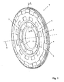
- the Fig. 1 shows a generally designated 1 starter disk according to the invention.
- the starter disk 1 comprises a disk body or toothed ring carrier 2, on the outer circumference or outer circumferential surface of which a starter toothed ring 3 having an outer toothing 4 is arranged. In the external teeth 4, the pinion of a starter, not shown intervention.
- the disk body 2 and the starter ring gear 3 are formed as separate parts or components that can perform a rotational and / or an axial movement to each other.
- the axial movement refers to the central axis of rotation or rotation axis 5.
- the starter disk 1 further comprises a plate spring 6 with a perforation 7, which presses the starter ring gear 3 in an axial direction against the disk body 2, as explained in more detail below.
- the plate spring 7 is rotatably attached via a flange 8 by means of rivets 9 on the disk body 2. Instead of riveting, a welding or the like may be provided.
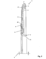
- the Fig. 2 shows the starter disk 1 of Fig. 1 in a sectional view according to the specified section AA in the Fig. 1 , Shown here is only the upper half of symmetry of the starter disk 1, ie above the axis of rotation 5.
- the disk body 2 and the starter ring gear 3 are formed as separate parts or components.
- the starter ring gear 3 rests with its inner circumferential surface on an outer peripheral surface of the disk body 2. Between the two contact surfaces, a frictional engagement is given, over which can be transmitted in the circumferential direction torques from the starter ring gear 3 to the disk body 2.
- the contact surfaces ie, the outer peripheral surface of the disk carrier 2 and the inner peripheral surface of the starter ring gear 3, are tapered, that is, these contact surfaces have an increasing diameter from left to right as shown in the axial direction. Due to this design, on the one hand, the contact surfaces are increased compared to a cylindrical design, on the other hand, a kind of friction cone is formed between the contact surfaces.
- the force that can be transmitted via such a friction cone, or the torque or friction torque that can be transmitted via it, can be adjusted by a force F N acting in the axial direction.
- the transferable frictional force results in approximation from the Coulomb's law, as already explained above.
- the axial force F N can be adjusted by means of the plate spring 6 so that the torque required for the engine start can just be transferred and a torque beyond this limit, that is no longer transmitted.
- the axial force F N is provided here by the plate spring 6.
- the disc spring 6 also allows the starter ring gear 3 and the disc body 2 can move in the axial direction relative to each other, for example, to compensate for thermal expansion due to the friction can.
- An improved heat dissipation is also achieved by the perforation 7 of the plate spring 6, as in the Fig. 1 shown.
- the plate spring 6 presses with its outer region or with the region of its outer diameter 61 in the axial direction against the starter ring gear 3. With its inner region or in the region of its inner diameter 62, the plate spring 6 is supported in the axial direction against a flange or sheet metal flange 8 and thereby also biased.
- the flange 8 is formed double angled and rotatably secured by means of rivets 9 on the disk body 2.
- the disk body 2 in particular for weight savings, is not solid, but has a substantially constant material thickness, which can be intercepted mechanically and / or thermally induced material stresses well.
- Fig. 3 shows in an enlarged view of the contact surface area or the conical friction surface arrangement between the starter ring gear 3 and the disk body 2. The above remarks to Fig. 2 apply accordingly.
- the Fig. 4 shows an example of a preferred arrangement of such a starter disk 1 in the drive train of a motor vehicle.
- the rotating starter disk 1 is supported by means of a roller bearing 11 directly on the engine block 12 of the motor vehicle.
- the disk body 2 on a cylindrical portion 21 which surrounds or limits the central recess of the disk body 2 (see also Fig. 2 ).
- the starter disk 1 When starting or starting the internal combustion engine of the starter ring gear 3 of the starter disk 1 is driven in rotation by the pinion of a starter, not shown. By frictional engagement between the inner peripheral surface of the starter ring gear 3 and the outer peripheral surface of the disc body 2, torque is transmitted from the starter ring gear 3 to the disc body 2. From here, a torque is transmitted to a dual-mass flywheel 13, which in turn rotatably drives a crankshaft 14 of the internal combustion engine to be started.
- the starter disk 1 is connected to the primary flywheel or primary flywheel of the dual mass flywheel 13. Instead of a rigid connection between the starter disk 1 and the dual mass flywheel 13 and a freewheel 15 may be provided.
- the Dual mass flywheel 13 are decoupled from the rotational movement of the starter disk 1 load-dependent. This allows, for example, that the pinion of the starter is permanently engaged with the outer toothing 4 of the starter ring gear 3 or remains permanently lashed.
Landscapes
- Engineering & Computer Science (AREA)
- General Engineering & Computer Science (AREA)
- Mechanical Engineering (AREA)
- Chemical & Material Sciences (AREA)
- Combustion & Propulsion (AREA)
- Physics & Mathematics (AREA)
- Acoustics & Sound (AREA)
- Aviation & Aerospace Engineering (AREA)
- Connection Of Motors, Electrical Generators, Mechanical Devices, And The Like (AREA)
Description
- Die vorliegende Erfindung betrifft eine Anlasserscheibe zur Anordnung im Antriebsstrang eines Kraftfahrzeugs. Die Erfindung betrifft fernerhin eine Anlassereinheit umfassend eine solche Anlasserscheibe.
- Eine Anlasserscheibe oder auch Anlasserrad dient dazu, das Drehmoment eines Anlassers mittelbar oder unmittelbar auf die Kurbelwelle des Verbrennungsmotors eines Kraftfahrzeugs zu übertragen, um diesen anzulassen bzw. zu starten. Ein solcher Anlasser kann bspw. ein Elektromotor sein, der über die Fahrzeugbatterie betrieben ist. Im Sinne der Patentanmeldung umfasst der Begriff Kraftfahrzeuge auch Lastkraftwagen, Landmaschinen und dergleichen. Eine Anlasserscheibe umfasst einen Anlasserzahnkranz, der auf einem Scheibenkörper bzw. Zahnkranzträger angeordnet ist. In die Zahnräder des Anlasserzahnkranzes greift ein Ritzel des Anlassers ein und treibt den Anlasserzahnkranz zusammen mit dem Scheibenkörper rotatorisch an.
- Ein Anlasserzahnkranz ist bspw. aus der
DE 10 2005 021 161 A1 derselben Anmeldering bekannt. Eine weitere Anlasserscheibe ist aus derJP 63 018 185 - Nachteilig bei den aus dem Stand der Technik bekannten Lösungen ist, dass insbesondere zu Beginn des Startvorgangs hohe Drehmomente auftreten. Dies führt zu dynamischen Effekten, die vom Fahrer als subjektiv störend empfunden werden können.
- Eine Aufgabe der Erfindung ist es, das beim Anlassen eines Verbrennungsmotors übertragene Drehmoment zu begrenzen.
- Diese Aufgabe wird gelöst von einer Anlasserscheibe gemäß Anspruch 1. Vorteilhafte und bevorzugte Weiterbildungen sind Gegenstand der hiervon abhängigen Ansprüche. Eine Anlassereinheit umfassend eine erfindungsgemäße Anlasserscheibe ist Gegenstand eines nebengeordneten Anspruches. Deren vorteilhafte und bevorzugte Weiterbildungen sind Gegenstand der hiervon abhängigen Ansprüche.
- Erfindungsgemäß wird eine Anlasserscheibe zur Anordnung im Antriebsstrang eines Kraftfahrzeugs, vorgeschlagen umfassend einen Scheibenkörper und einen Anlasserzahnkranz, der am Außenumfang des Scheibenkörpers angeordnet ist, wobei der Scheibenkörper und der Anlasserzahnkranz als separate Teile bzw. Komponenten ausgebildet sind, zwischen denen eine Rutschkupplung wirksam ist, um das übertragbare Drehmoment vom Anlasserzahnkranz auf den Scheibenkörper zu begrenzen.
- Der Scheibenkörper kann auch als Zahnkranzträger bezeichnet werden. Der Scheibenkörper ist bevorzugt als Lochscheibe, als Vollscheibe oder als Ringkörper ausgebildet. Der Anlasserzahnkranz ist bevorzugt als Ringkörper ausgebildet und weist bevorzugt eine Außenverzahnung auf, die auf dessen Außenumfangsfläche ausgebildet ist. Der Scheibenkörper und/oder der Zahnkranzträger können einteilig oder mehrteilig ausgebildet sein.
- Die erfindungsgemäße Lösung hat viele Vorteile. Ein wesentlicher Vorteil ist darin zu sehen, dass auf einfache und damit auch kostengünstige Weise das mit der Anlasserscheibe übertragbare Drehmoment begrenzt wird. Damit kann auch das Drehmoment zwischen dem Anlasser und dem Verbrennungsmotor begrenzt bzw. limitiert werden. Als Folge können wesentliche Bauteile des Systems für ein geringeres Maximalmoment ausgelegt werden, was Bauraum, Gewicht und Kosten einspart. Weiterhin werden die konstruktiven Freiheitsgrade erhöht, bspw. indem nunmehr auch Kunststoffteile verwendet werden können. Zudem kann die Geräuschentwicklung beim Starten bzw. Anlassen des Verbrennungsmotors reduziert und die subjektiv wahrnehmbare Startqualität bzw. Anlassqualität verbessert werden.
- Gemäß einer bevorzugten Weiterbildung ist vorgesehen, dass zwischen der Innenumfangsfläche des Anlasserzahnkranzes und der Außenumfangsfläche des Scheibenkörpers ein Reibschluss gegeben ist, mittels dessen ein Drehmoment vom Anlasserzahnkranz auf den Scheibenkörper übertragbar ist, wobei über diesen Reibschluss gleichfalls die Rutschkupplung realisiert ist. Eine derartige quasi integrierte Rutschkupplung ist in vorteilhafter Weise sowohl platzneutral als auch kostengünstig in der Herstellung bzw. Montage. Bei der Rutschkupplung handelt es sich demnach um eine Reibkupplung.
- Gemäß einer bevorzugten Weiterbildung ist vorgesehen, dass die Innenumfangsfläche des Anlasserzahnkranzes konisch und die Außenumfangsfläche des Scheibenkörpers korrespondierend hierzu ebenfalls konisch ausgebildet ist. Auf diese Weise können bei einer gleichen axialen Breite die korrespondierenden Reibflächen vergrößert werden.
- Gemäß einer bevorzugten Weiterbildung ist vorgesehen, dass der Anlasserzahnkranz mit seiner konischen Innenumfangsfläche gegen die konische Außenumfangsfläche des Scheibenkörpers gedrückt wird, wozu der Anlasserzahnkranz in einer axialen Richtung mit einer Kraft beaufschlagt ist. Die axiale Richtung ist durch die Rotationsachse der Anlasserscheibe bestimmt. Die Kraftbeaufschlagung des Anlasserzahnkranzes erfolgt in Richtung auf den Scheibenkörper. Im Falle der konischen Ausbildung der Kontaktflächen bzw. Reibflächen ist bevorzugt vorgesehen, dass eine konische Aufweitung der Reibflächendurchmesser in der Richtung der axialen Kraftaufbringung erfolgt. Dadurch werden die korrespondierenden Reibflächen in der Art eines Reibungskegels verstärkt aneinander gepresst. Die sich ergebende Reibkraft FR kann näherungsweise über das Coulombsche Reibgesetz FR = µ · FN bestimmt werden, wobei FN der in Axialrichtung aufgebrachten Normalenkraft entspricht, mit welcher der Anlasserzahnkranz gegen den Scheibenkörper gedrückt wird, und µ den Reibwert bzw. Reibbeiwert der Reibflächenpaarung angibt. Das zwischen dem Anlasserzahnkranz und dem Scheibenkörper übertragbare Drehmoment ist damit durch Wahl der axialen Kraft bzw. Druckkraft, mit welcher der Anlasserzahnkranz gegen den Scheibenkörper gedrückt oder gepresst wird, einstellbar.
- Gemäß einer bevorzugten Weiterbildung ist vorgesehen, dass der Anlasserzahnkranz mittels wenigstens einer Tellerfeder in der axialen Richtung kraftbeaufschlagt ist. Eine Tellerfeder kann in vorteilhafter Weise bei einem geringen axialen Platzbedarf hohe axiale Kräfte erzeugen.
- Gemäß einer bevorzugten Weiterbildung hiervon ist vorgesehen, dass die Tellerfeder mit einer Lochung bzw. gelocht, oder mit Ausnehmungen, ausgebildet ist. Dies führt zu einer Gewichtsersparnis und kann auch die Elastizität der Tellerfeder verbessern. Zudem kann über die Lochung die Federkraft bzw. Elastizität eingestellt werden. Weiterhin kann durch die Lochung eine verbesserte Kühlung erreicht werden.
- Gemäß einer bevorzugten Weiterbildung ist vorgesehen, dass die Tellerfeder im Bereich ihres Innendurchmessers mittels eines Flansches vorgespannt ist, wobei dieser Flansch drehfest mit dem Scheibenkörper verbunden ist. Bevorzugt ist vorgesehen, dass die Tellerfeder mit ihrem radial äußeren Bereich gegen den Anlasserzahnkranz drückt und sich mit ihrem radial inneren Bereich abstützt. Der radial innere Bereich bzw. Bereich des Innendurchmessers lässt sich bevorzugt als ein an einer zentralen Ausnehmung bzw. Öffnung der Tellerfeder radial angrenzender Bereich auffassen. Bevorzugt ist der Flansch als Blechflansch ausgebildet und mit dem Scheibenkörper vernietet.
- Eine erfindungsgemäße Anlassereinheit zur Anordnung im Antriebsstrang eines Kraftfahrzeugs umfasst eine erfindungsgemäße Anlasserscheibe, in der zuvor beschriebenen Art.
- Gemäß einer bevorzugten Weiterbildung der Anlassereinheit ist vorgesehen, dass die Anlasserscheibe mittels wenigstens eines Wälzlagers am Motorblock des Kraftfahrzeugs abgestützt bzw. befestigt ist.
- Erfindungsgemässes ist vorgesehen, dass die Anlasserscheibe mittels eines Freilaufs mit einer Schwungscheibe oder einem Zweimassenschwungrad des Antriebsstranges verbunden ist. Bevorzugt ist die Anlasserscheibe mit der Primärschwungscheibe bzw. Primärschwungmasse eines Zweimassenschwungrades verbunden. Unter einem Freilauf wird eine mechanische Einrichtung verstanden, die einen Teil eines Antriebstranges von der Drehbewegung definiert entkoppelt, wenn sich die Lastverhältnisse ändern.
- Alternativ kann die erfindungsgemäße Anlasserscheibe auch als Schwungrad ausgebildet sein. Hierbei kann insbesondere vorgesehen sein, dass die Anlasserscheibe als Primärschwungrad eines Zweimassenschwungrades ausgebildet ist.
- Im Folgenden wird ein bevorzugtes Ausführungsbeispiel der Erfindung anhand der beiliegenden Zeichnungen erläutert. Dabei zeigen:
- Fig. 1
- ein Ausführungsbeispiel der erfindungsgemäßen Anlasserscheibe in einer perspektivischen Ansicht;
- Fig. 2
- einen Schnitt durch die Anlasserscheibe der
Fig. 1 , gemäß dem Schnittverlauf A-A; - Fig. 3
- eine Detailansicht aus der
Fig. 2 ; und - Fig. 4
- eine bevorzugte Anordnung der Anlasserscheibe im Antriebsstrang eines Kraftfahrzeugs in einer schematischen Ansicht.
- Die
Fig. 1 zeigt eine insgesamt mit 1 bezeichnete erfindungsgemäße Anlasserscheibe. Die Anlasserscheibe 1 umfasst einen Scheibenkörper bzw. Zahnkranzträger 2, an dessen Außenumfang bzw. Außenumfangsfläche ein Anlasserzahnkranz 3 mit einer Außenverzahnung 4 angeordnet ist. In die Außenverzahnung 4 kann das Ritzel eines nicht gezeigten Anlassers eingreifen. Der Scheibenkörper 2 und der Anlasserzahnkranz 3 sind als separate Teile bzw. Bauteile ausgebildet, die zueinander eine rotatorische und/oder eine axiale Bewegung ausführen können. Die axiale Bewegung bezieht sich auf die zentrale Drehachse bzw. Rotationsachse 5. Die Anlasserscheibe 1 umfasst weiterhin eine Tellerfeder 6 mit einer Lochung 7, welche den Anlasserzahnkranz 3 in einer axialen Richtung gegen den Scheibenkörper 2 drückt, wie nachfolgend noch näher erläutert. Die Tellerfeder 7 ist über einen Flansch 8 mittels von Nieten 9 am Scheibenkörper 2 drehfest befestigt. Anstelle einer Vernietung kann auch eine Verschweißung oder dergleichen vorgesehen sein. - Die
Fig. 2 zeigt die Anlasserscheibe 1 derFig. 1 in einer Schnittansicht gemäß dem angegebenen Schnittverlauf A-A in derFig. 1 . Dargestellt ist hier nur die obere Symmetriehälfte der Anlasserscheibe 1, d.h. oberhalb der Rotationsachse 5. Wie bereits oben dargelegt, sind der Scheibenkörper 2 und der Anlasserzahnkranz 3 als separate Teile bzw. Komponenten ausgebildet. Der Anlasserzahnkranz 3 liegt hierbei mit seiner Innenumfangsfläche an einer Außenumfangsfläche des Scheibenkörpers 2 an. Zwischen den beiden Kontaktflächen ist ein Reibschluss gegeben, über den sich in Umfangsrichtung Drehmomente vom Anlasserzahnkranz 3 auf den Scheibenkörper 2 übertragen lassen. Bei Überschreitung einer maximal übertragbaren Kraft bzw. eines maximal übertragbaren Drehmoments beginnen diese Kontaktflächen aufeinander abzurutschen bzw. abzugleiten, wodurch eine rotatorische Relativbewegung zwischen dem Anlasserzahnkranz 3 und dem Scheibenkörper 2 gegeben ist. Auf diese Weise kann das maximal übertragbare Drehmoment vom Anlasserzahnkranz 3 auf den Scheibenkörper 2 begrenzt werden. Bei Unterschreiten der maximal übertragbaren Kraft bzw. des maximal übertragbaren Drehmomentes tritt wiederum Reibschluss ein. - Wie in der
Fig. 2 gezeigt, sind die Kontaktflächen, d.h. die Außenumfangsfläche des Scheibenträgers 2 und die Innenumfangsfläche des Anlasserzahnkranzes 3, konisch ausgebildet, d.h. diese Kontaktflächen weisen gemäß der gezeigten Darstellung in der axialen Richtung von links nach rechts einen ansteigenden Durchmesser auf. Aufgrund dieser Ausbildung werden zum einen die Kontaktflächen gegenüber einer zylindrischen Ausbildung vergrößert, zum anderen wird zwischen den Kontaktflächen eine Art Reibungskegel ausgebildet. Die über einen solchen Reibungskegel übertragbare Kraft, bzw. das hierüber übertragbare Drehmoment bzw. Reibmoment, kann durch eine in Axialrichtung wirkende Kraft FN eingestellt werden. Die übertragbare Reibkraft ergibt sich in Näherung aus dem Coulombschen Gesetz, wie bereits oben erläutert. So kann bspw. die Axialkraft FN mittels der Tellerfeder 6 so eingestellt werden, dass das für den Motorstart erforderliche Drehmoment gerade noch übertragen werden kann und ein darüber hinausgehendes Drehmoment limitiert, d.h. nicht mehr übertragen wird. - Die Axialkraft FN wird hier durch die Tellerfeder 6 bereitgestellt. Die Tellerfeder 6 ermöglicht zudem, dass sich der Anlasserzahnkranz 3 und der Scheibenkörper 2 auch in axialer Richtung relativ zueinander bewegen können, um bspw. eine Wärmeausdehnung in Folge der Reibung ausgleichen zu können. Eine verbesserte Wärmeabfuhr wird auch durch die Lochung 7 der Tellerfeder 6 erzielt, wie in der
Fig. 1 gezeigt. Die Tellerfeder 6 drückt mit ihrem äußeren Bereich bzw. mit dem Bereich ihres Außendurchmessers 61 in axialer Richtung gegen den Anlasserzahnkranz 3. Mit ihrem inneren Bereich bzw. im Bereich ihres Innendurchmessers 62 ist die Tellerfeder 6 in axialer Richtung gegen einen Flansch bzw. Blechflansch 8 abgestützt und hierdurch auch vorgespannt. Der Flansch 8 ist doppelt abgewinkelt ausgebildet und mittels von Nieten 9 am Scheibenkörper 2 drehfest befestigt. - Der
Fig. 2 ist ferner zu entnehmen, das der Scheibenkörper 2, insbesondere zur Gewichtsersparnis, nicht massiv ausgebildet ist, jedoch eine im wesentlichen konstante Materialdicke aufweist, wodurch sich mechanisch und/oder thermisch bedingte Materialspannungen gut abfangen lassen. - Die
Fig. 3 zeigt in einer vergrößerten Ansicht den Kontaktflächenbereich bzw. die konische Reibflächenanordnung zwischen dem Anlasserzahnkranz 3 und dem Scheibenkörper 2. Die obigen Ausführungen zurFig. 2 gelten entsprechend. - Die
Fig. 4 zeigt beispielhaft eine bevorzugte Anordnung einer solchen Anlasserscheibe 1 im Antriebsstrang eines Kraftfahrzeugs. Die rotierende Anlasserscheibe 1 stützt sich mittels eines Wälzlagers 11 direkt am Motorblock 12 des Kraftfahrzeugs ab. Hierzu weist der Scheibenkörper 2 einen zylindrischen Abschnitt 21 auf, welcher die zentrale Ausnehmung des Scheibenkörpers 2 umgibt bzw. begrenzt (siehe auchFig. 2 ). - Beim Starten bzw. Anlassen des Verbrennungsmotors wird der Anlasserzahnkranz 3 der Anlasserscheibe 1 von dem Ritzel eines nicht gezeigten Anlassers rotatorisch angetrieben. Durch Reibschluss zwischen der Innenumfangsfläche des Anlasserzahnkranzes 3 und der Außenumfangsfläche des Scheibenkörpers 2 wird ein Drehmoment vom Anlasserzahnkranz 3 auf den Scheibenkörper 2 übertragen. Von hier erfolgt eine Drehmomentenübertragung auf ein Zweimassenschwungrad 13, welches seinerseits eine Kurbelwelle 14 des zu startenden Verbrennungsmotors rotatorisch antreibt. Bevorzugt ist die Anlasserscheibe 1 mit der Primärschwungscheibe bzw. Primärschwungmasse des Zweimassenschwungrades 13 verbunden. Anstelle einer starren Verbindung zwischen der Anlasserscheibe 1 und dem Zweimassenschwungrad 13 kann auch ein Freilauf 15 vorgesehen sein. Mittels des Freilaufes 15 kann das Zweimassenschwungrad 13 von der Drehbewegung der Anlasserscheibe 1 lastabhängig entkoppelt werden. Dies ermöglicht z.B., dass das Ritzel des Anlassers permanent mit der Außenverzahnung 4 des Anlasserzahnkranzes 3 im Eingriff steht bzw. dauerhaft eingespurt verbleibt.
-
- 1
- Anlasserscheibe; Anlasserrad
- 2
- Scheibenkörper; Zahnkranzträger
- 21
- zylindrischer Abschnitt am Scheibenkörper
- 3
- Anlasserzahnkranz
- 4
- Außenverzahnung; Verzahnung des Anlasserzahnkranzes
- 5
- Drehachse; Rotationsachse (axiale Richtung)
- 6
- Tellerfeder
- 61
- Bereich des Außendurchmessers der Tellerfeder; äußerer Bereich
- 62
- Bereich des Innendurchmessers der Tellerfeder; innerer Bereich
- 7
- Lochung (der Tellerfeder); Ausnehmungen
- 8
- Flansch; Befestigungsflansch für Tellerfeder
- 9
- Niete(n)
- 11
- Wälzlager
- 12
- Motorblock
- 13
- Zweimassenschwungrad
- 14
- Kurbelwelle
- 15
- Freilauf
Claims (8)
- Anlassereinheit zur Anordnung im Antriebsstrang eines Kraftfahrzeugs mit einer Anlasserscheibe (1), umfassend einen Scheibenkörper (2) und einen Anlasserzahnkranz (3), der am Außenumfang des Scheibenkörpers (2) angeordnet ist, wobei der Scheibenkörper (2) und der Anlasserzahnkranz (3) als separate Teile ausgebildet sind, zwischen denen eine Rutschkupplung wirksam ist, um das übertragbare Drehmoment vom Anlasserzahnkranz (3) auf den Scheibenkörper (2) zu begrenzen, dadurch gekennzeichnet, dass die Anlasserscheibe (1) mittels eines Freilaufs (15) mit einer Schwungscheibe oder einem Zweimassenschwungrad (13) des Antriebsstranges verbunden ist.
- Anlassereinheit nach Anspruch 1, dadurch gekennzeichnet, dass die Anlasserscheibe (1) mittels wenigstens eines Wälzlagers (11) am Motorblock (12) des Kraftfahrzeugs abgestützt ist.
- Anlassereinheit nach Anspruch 1 oder 2, dadurch gekennzeichnet, dass zwischen der Innenumfangsfläche des Anlasserzahnkranzes (3) und der Außenumfangsfläche des Scheibenkörpers (2) ein Reibschluss gegeben ist, mittels dessen ein Drehmoment vom Anlasserzahnkranz (3) auf den Scheibenkörper (2) übertragbar ist, wobei über diesen Reibschluss gleichfalls die Rutschkupplung realisiert ist.
- Anlassereinheit nach einem der Ansprüche 1 bis 3, dadurch gekennzeichnet, dass die Innenumfangsfläche des Anlasserzahnkranzes (3) konisch und die Außenumfangsfläche des Scheibenkörpers (2) hierzu korrespondierend ebenfalls konisch ausgebildet ist.
- Anlassereinheit nach Anspruch 4, dadurch gekennzeichnet, dass der Anlasserzahnkranz (3) mit seiner konischen Innenumfangsfläche gegen die konische Außenumfangsfläche des Scheibenkörpers (2) gedrückt wird, wozu der Anlasserzahnkranz (3) in einer axialen Richtung mit einer Kraft (FN) beaufschlagt ist.
- Anlassereinheit nach Anspruch 5, dadurch gekennzeichnet, dass der Anlasserzahnkranz (3) mittels wenigstens einer Tellerfeder (6) in der axialen Richtung kraftbeaufschlagt ist.
- Anlassereinheit nach Anspruch 6, dadurch gekennzeichnet, dass die Tellerfeder mit einer Lochung (7) ausgebildet ist.
- Anlassereinheit nach Anspruch 6 oder 7, dadurch gekennzeichnet, dass die Tellerfeder (6) im Bereich (62) ihres Innendurchmessers mittels eines Flansches (8) vorgespannt ist, wobei dieser Flansch (8) drehfest mit dem Scheibenkörper (2) verbunden ist.
Applications Claiming Priority (2)
| Application Number | Priority Date | Filing Date | Title |
|---|---|---|---|
| DE102008058686 | 2008-11-24 | ||
| PCT/DE2009/001620 WO2010057468A2 (de) | 2008-11-24 | 2009-11-12 | Anlasserscheibe mit rutschkupplung |
Publications (2)
| Publication Number | Publication Date |
|---|---|
| EP2368058A2 EP2368058A2 (de) | 2011-09-28 |
| EP2368058B1 true EP2368058B1 (de) | 2015-01-07 |
Family
ID=42114838
Family Applications (1)
| Application Number | Title | Priority Date | Filing Date |
|---|---|---|---|
| EP09795309.5A Not-in-force EP2368058B1 (de) | 2008-11-24 | 2009-11-12 | Anlasserscheibe mit rutschkupplung |
Country Status (4)
| Country | Link |
|---|---|
| EP (1) | EP2368058B1 (de) |
| CN (1) | CN102224358B (de) |
| DE (2) | DE112009002709A5 (de) |
| WO (1) | WO2010057468A2 (de) |
Families Citing this family (2)
| Publication number | Priority date | Publication date | Assignee | Title |
|---|---|---|---|---|
| CN108298398B (zh) * | 2017-01-13 | 2020-09-01 | 奥的斯电梯公司 | 用于电梯限速器的芯环组件,限速器和电梯系统 |
| DE102019134274B3 (de) * | 2019-12-13 | 2021-03-18 | Schaeffler Technologies AG & Co. KG | Startervorrichtung mit einem verspannenden Federelement |
Family Cites Families (10)
| Publication number | Priority date | Publication date | Assignee | Title |
|---|---|---|---|---|
| US1453129A (en) * | 1919-08-14 | 1923-04-24 | Walter J Conlon | Clutch for washing machines |
| US1845637A (en) * | 1930-05-09 | 1932-02-16 | Edward R Wharton | Starter mechanisms |
| DE2949990A1 (de) * | 1979-12-12 | 1981-06-19 | Hilti AG, 9494 Schaan | Reibkupplung zum uebertragen eines begrenzten drehmomentes |
| DE3409868A1 (de) * | 1984-03-17 | 1985-09-19 | Fichtel & Sachs Ag, 8720 Schweinfurt | Kupplungsscheibe |
| JPS6318185A (ja) * | 1986-07-10 | 1988-01-26 | Kawasaki Heavy Ind Ltd | 内燃機関の始動装置 |
| FR2772433B1 (fr) * | 1997-12-17 | 2000-02-04 | Valeo Equip Electr Moteur | Demarreur de vehicule automobile comportant un lanceur perfectionne |
| FR2831233B1 (fr) * | 2001-10-23 | 2004-01-16 | Valeo | Embrayage a friction, pour vehicule automobile, equipe d'un dispositif de rattrapage de jeu pilote |
| JP2005133859A (ja) * | 2003-10-31 | 2005-05-26 | Aisin Seiki Co Ltd | トルク変動吸収装置 |
| DE102005021161A1 (de) | 2004-05-12 | 2005-12-15 | Luk Lamellen Und Kupplungsbau Beteiligungs Kg | Anlasserzahnkranz sowie Schwungrad mit einem derartigen Anlasserzahnkranz |
| CA2497190C (en) * | 2005-01-27 | 2009-04-21 | Brian K. Bosk | Wedge clutch assembly |
-
2009
- 2009-11-12 EP EP09795309.5A patent/EP2368058B1/de not_active Not-in-force
- 2009-11-12 DE DE112009002709T patent/DE112009002709A5/de not_active Withdrawn
- 2009-11-12 DE DE102009052980A patent/DE102009052980A1/de not_active Withdrawn
- 2009-11-12 WO PCT/DE2009/001620 patent/WO2010057468A2/de not_active Ceased
- 2009-11-12 CN CN200980146965.9A patent/CN102224358B/zh not_active Expired - Fee Related
Also Published As
| Publication number | Publication date |
|---|---|
| CN102224358B (zh) | 2015-01-07 |
| WO2010057468A2 (de) | 2010-05-27 |
| CN102224358A (zh) | 2011-10-19 |
| DE112009002709A5 (de) | 2013-10-31 |
| WO2010057468A3 (de) | 2010-07-29 |
| EP2368058A2 (de) | 2011-09-28 |
| DE102009052980A1 (de) | 2010-05-27 |
Similar Documents
| Publication | Publication Date | Title |
|---|---|---|
| EP3105464A1 (de) | Normal-eingerückte kupplungsvorrichtung | |
| EP3123051B1 (de) | Nachstelleinrichtung für eine reibkupplung | |
| EP3314138B1 (de) | Antriebsstrang für ein kraftfahrzeug mit einer reibungskupplung und reibungskupplung für einen antriebsstrang eines kraftfahrzeugs | |
| EP3788272B1 (de) | Reibkupplungseinrichtung, hybridmodul und antriebsanordnung für ein kraftfahrzeug | |
| DE102017123977B4 (de) | Kupplungsvorrichtung für einen Antriebsstrang eines Fahrzeuges mit zumindest einem von einer Anpressplatte rotatorisch entkoppelten Federelement | |
| EP2368058A2 (de) | Anlasserscheibe mit rutschkupplung | |
| DE102014205064A1 (de) | Kupplung aufweisend einen Druckring mit Bajonettverschluss | |
| DE102009053034B4 (de) | Kupplung | |
| DE102013203343A1 (de) | Nachstelleinrichtung für eine Reibkupplung | |
| EP3123048B1 (de) | Weggesteuerte nachstelleinrichtung für eine reibkupplung | |
| DE102014209973A1 (de) | Rotationsbauteil, Verfahren zum Herstellen eines Rotationsbauteils, Lamellenträger sowie Drehmomentübertragungseinrichtung | |
| DE102017115612A1 (de) | Schaltzugmitteleinheit mit einer Rotationsachse für eine Verbrennungskraftmaschine | |
| DE102012207244A1 (de) | Kupplungsanordnung für Traktoren mit PTO | |
| EP3123053B1 (de) | Nachstelleinrichtung für eine reibkupplung | |
| DE102015216088A1 (de) | Reibkupplung für einen Antriebsstrang eines Kraftfahrzeugs | |
| DE102017129280A1 (de) | Hybridmodul für einen Antriebsstrang eines Hybridfahrzeugs sowie ein solcher Antriebsstrang | |
| EP1571031B1 (de) | Antriebsanordnung | |
| DE102017129272B4 (de) | Hybridmodul mit Zwischenwand mit Gewindelochbereich; sowie Hybridantriebsstrang | |
| EP2957789A2 (de) | Stützfeder für ein betätigungssystem einer reibkupplung | |
| DE102016205419A1 (de) | Verbindungselemente für ein Doppelflansch-Fliehkraftpendel | |
| EP4051920B1 (de) | Drehmomentbegrenzer mit einer rotationsachse für einen antriebsstrang | |
| DE102013212429A1 (de) | Reibkupplung mit weggesteuerter Verschleißnachstelleinrichtung | |
| DE102009056772A1 (de) | Schwungrad | |
| EP3592590B1 (de) | Hybridmodul mit schwungrad; sowie hybridantriebsstrang | |
| DE19736558A1 (de) | Reibungskupplung, insbesondere für Kraftfahrzeuge |
Legal Events
| Date | Code | Title | Description |
|---|---|---|---|
| PUAI | Public reference made under article 153(3) epc to a published international application that has entered the european phase |
Free format text: ORIGINAL CODE: 0009012 |
|
| 17P | Request for examination filed |
Effective date: 20110624 |
|
| AK | Designated contracting states |
Kind code of ref document: A2 Designated state(s): AT BE BG CH CY CZ DE DK EE ES FI FR GB GR HR HU IE IS IT LI LT LU LV MC MK MT NL NO PL PT RO SE SI SK SM TR |
|
| DAX | Request for extension of the european patent (deleted) | ||
| RAP1 | Party data changed (applicant data changed or rights of an application transferred) |
Owner name: SCHAEFFLER TECHNOLOGIES AG & CO. KG |
|
| RAP1 | Party data changed (applicant data changed or rights of an application transferred) |
Owner name: SCHAEFFLER TECHNOLOGIES GMBH & CO. KG |
|
| REG | Reference to a national code |
Ref country code: DE Ref legal event code: R079 Ref document number: 502009010481 Country of ref document: DE Free format text: PREVIOUS MAIN CLASS: F16F0015129000 Ipc: F02D0041020000 |
|
| RIC1 | Information provided on ipc code assigned before grant |
Ipc: F16D 7/02 20060101ALI20140515BHEP Ipc: F16F 15/129 20060101ALI20140515BHEP Ipc: F02D 41/02 20060101AFI20140515BHEP Ipc: F02N 15/06 20060101ALI20140515BHEP Ipc: F02N 15/02 20060101ALI20140515BHEP |
|
| GRAP | Despatch of communication of intention to grant a patent |
Free format text: ORIGINAL CODE: EPIDOSNIGR1 |
|
| INTG | Intention to grant announced |
Effective date: 20140728 |
|
| GRAS | Grant fee paid |
Free format text: ORIGINAL CODE: EPIDOSNIGR3 |
|
| GRAA | (expected) grant |
Free format text: ORIGINAL CODE: 0009210 |
|
| AK | Designated contracting states |
Kind code of ref document: B1 Designated state(s): AT BE BG CH CY CZ DE DK EE ES FI FR GB GR HR HU IE IS IT LI LT LU LV MC MK MT NL NO PL PT RO SE SI SK SM TR |
|
| REG | Reference to a national code |
Ref country code: GB Ref legal event code: FG4D Free format text: NOT ENGLISH |
|
| REG | Reference to a national code |
Ref country code: CH Ref legal event code: EP |
|
| REG | Reference to a national code |
Ref country code: IE Ref legal event code: FG4D Free format text: LANGUAGE OF EP DOCUMENT: GERMAN |
|
| REG | Reference to a national code |
Ref country code: AT Ref legal event code: REF Ref document number: 705906 Country of ref document: AT Kind code of ref document: T Effective date: 20150215 |
|
| REG | Reference to a national code |
Ref country code: DE Ref legal event code: R096 Ref document number: 502009010481 Country of ref document: DE Effective date: 20150226 |
|
| RAP2 | Party data changed (patent owner data changed or rights of a patent transferred) |
Owner name: SCHAEFFLER TECHNOLOGIES AG & CO. KG |
|
| REG | Reference to a national code |
Ref country code: DE Ref legal event code: R081 Ref document number: 502009010481 Country of ref document: DE Owner name: SCHAEFFLER TECHNOLOGIES AG & CO. KG, DE Free format text: FORMER OWNER: SCHAEFFLER TECHNOLOGIES GMBH & CO. KG, 91074 HERZOGENAURACH, DE Effective date: 20150126 |
|
| REG | Reference to a national code |
Ref country code: NL Ref legal event code: VDEP Effective date: 20150107 |
|
| REG | Reference to a national code |
Ref country code: LT Ref legal event code: MG4D |
|
| PG25 | Lapsed in a contracting state [announced via postgrant information from national office to epo] |
Ref country code: LT Free format text: LAPSE BECAUSE OF FAILURE TO SUBMIT A TRANSLATION OF THE DESCRIPTION OR TO PAY THE FEE WITHIN THE PRESCRIBED TIME-LIMIT Effective date: 20150107 Ref country code: FI Free format text: LAPSE BECAUSE OF FAILURE TO SUBMIT A TRANSLATION OF THE DESCRIPTION OR TO PAY THE FEE WITHIN THE PRESCRIBED TIME-LIMIT Effective date: 20150107 Ref country code: BG Free format text: LAPSE BECAUSE OF FAILURE TO SUBMIT A TRANSLATION OF THE DESCRIPTION OR TO PAY THE FEE WITHIN THE PRESCRIBED TIME-LIMIT Effective date: 20150407 Ref country code: ES Free format text: LAPSE BECAUSE OF FAILURE TO SUBMIT A TRANSLATION OF THE DESCRIPTION OR TO PAY THE FEE WITHIN THE PRESCRIBED TIME-LIMIT Effective date: 20150107 Ref country code: SE Free format text: LAPSE BECAUSE OF FAILURE TO SUBMIT A TRANSLATION OF THE DESCRIPTION OR TO PAY THE FEE WITHIN THE PRESCRIBED TIME-LIMIT Effective date: 20150107 Ref country code: HR Free format text: LAPSE BECAUSE OF FAILURE TO SUBMIT A TRANSLATION OF THE DESCRIPTION OR TO PAY THE FEE WITHIN THE PRESCRIBED TIME-LIMIT Effective date: 20150107 Ref country code: NO Free format text: LAPSE BECAUSE OF FAILURE TO SUBMIT A TRANSLATION OF THE DESCRIPTION OR TO PAY THE FEE WITHIN THE PRESCRIBED TIME-LIMIT Effective date: 20150407 |
|
| PG25 | Lapsed in a contracting state [announced via postgrant information from national office to epo] |
Ref country code: GR Free format text: LAPSE BECAUSE OF FAILURE TO SUBMIT A TRANSLATION OF THE DESCRIPTION OR TO PAY THE FEE WITHIN THE PRESCRIBED TIME-LIMIT Effective date: 20150408 Ref country code: IS Free format text: LAPSE BECAUSE OF FAILURE TO SUBMIT A TRANSLATION OF THE DESCRIPTION OR TO PAY THE FEE WITHIN THE PRESCRIBED TIME-LIMIT Effective date: 20150507 Ref country code: PL Free format text: LAPSE BECAUSE OF FAILURE TO SUBMIT A TRANSLATION OF THE DESCRIPTION OR TO PAY THE FEE WITHIN THE PRESCRIBED TIME-LIMIT Effective date: 20150107 Ref country code: NL Free format text: LAPSE BECAUSE OF FAILURE TO SUBMIT A TRANSLATION OF THE DESCRIPTION OR TO PAY THE FEE WITHIN THE PRESCRIBED TIME-LIMIT Effective date: 20150107 Ref country code: LV Free format text: LAPSE BECAUSE OF FAILURE TO SUBMIT A TRANSLATION OF THE DESCRIPTION OR TO PAY THE FEE WITHIN THE PRESCRIBED TIME-LIMIT Effective date: 20150107 |
|
| REG | Reference to a national code |
Ref country code: DE Ref legal event code: R097 Ref document number: 502009010481 Country of ref document: DE |
|
| PG25 | Lapsed in a contracting state [announced via postgrant information from national office to epo] |
Ref country code: SK Free format text: LAPSE BECAUSE OF FAILURE TO SUBMIT A TRANSLATION OF THE DESCRIPTION OR TO PAY THE FEE WITHIN THE PRESCRIBED TIME-LIMIT Effective date: 20150107 Ref country code: CZ Free format text: LAPSE BECAUSE OF FAILURE TO SUBMIT A TRANSLATION OF THE DESCRIPTION OR TO PAY THE FEE WITHIN THE PRESCRIBED TIME-LIMIT Effective date: 20150107 Ref country code: RO Free format text: LAPSE BECAUSE OF FAILURE TO SUBMIT A TRANSLATION OF THE DESCRIPTION OR TO PAY THE FEE WITHIN THE PRESCRIBED TIME-LIMIT Effective date: 20150107 Ref country code: DK Free format text: LAPSE BECAUSE OF FAILURE TO SUBMIT A TRANSLATION OF THE DESCRIPTION OR TO PAY THE FEE WITHIN THE PRESCRIBED TIME-LIMIT Effective date: 20150107 Ref country code: EE Free format text: LAPSE BECAUSE OF FAILURE TO SUBMIT A TRANSLATION OF THE DESCRIPTION OR TO PAY THE FEE WITHIN THE PRESCRIBED TIME-LIMIT Effective date: 20150107 |
|
| PLBE | No opposition filed within time limit |
Free format text: ORIGINAL CODE: 0009261 |
|
| STAA | Information on the status of an ep patent application or granted ep patent |
Free format text: STATUS: NO OPPOSITION FILED WITHIN TIME LIMIT |
|
| REG | Reference to a national code |
Ref country code: FR Ref legal event code: PLFP Year of fee payment: 7 |
|
| 26N | No opposition filed |
Effective date: 20151008 |
|
| PG25 | Lapsed in a contracting state [announced via postgrant information from national office to epo] |
Ref country code: IT Free format text: LAPSE BECAUSE OF FAILURE TO SUBMIT A TRANSLATION OF THE DESCRIPTION OR TO PAY THE FEE WITHIN THE PRESCRIBED TIME-LIMIT Effective date: 20150107 |
|
| PG25 | Lapsed in a contracting state [announced via postgrant information from national office to epo] |
Ref country code: SI Free format text: LAPSE BECAUSE OF FAILURE TO SUBMIT A TRANSLATION OF THE DESCRIPTION OR TO PAY THE FEE WITHIN THE PRESCRIBED TIME-LIMIT Effective date: 20150107 |
|
| PG25 | Lapsed in a contracting state [announced via postgrant information from national office to epo] |
Ref country code: LU Free format text: LAPSE BECAUSE OF FAILURE TO SUBMIT A TRANSLATION OF THE DESCRIPTION OR TO PAY THE FEE WITHIN THE PRESCRIBED TIME-LIMIT Effective date: 20151112 Ref country code: MC Free format text: LAPSE BECAUSE OF FAILURE TO SUBMIT A TRANSLATION OF THE DESCRIPTION OR TO PAY THE FEE WITHIN THE PRESCRIBED TIME-LIMIT Effective date: 20150107 |
|
| REG | Reference to a national code |
Ref country code: CH Ref legal event code: PL |
|
| GBPC | Gb: european patent ceased through non-payment of renewal fee |
Effective date: 20151112 |
|
| PG25 | Lapsed in a contracting state [announced via postgrant information from national office to epo] |
Ref country code: LI Free format text: LAPSE BECAUSE OF NON-PAYMENT OF DUE FEES Effective date: 20151130 Ref country code: CH Free format text: LAPSE BECAUSE OF NON-PAYMENT OF DUE FEES Effective date: 20151130 |
|
| REG | Reference to a national code |
Ref country code: IE Ref legal event code: MM4A |
|
| PG25 | Lapsed in a contracting state [announced via postgrant information from national office to epo] |
Ref country code: GB Free format text: LAPSE BECAUSE OF NON-PAYMENT OF DUE FEES Effective date: 20151112 Ref country code: IE Free format text: LAPSE BECAUSE OF NON-PAYMENT OF DUE FEES Effective date: 20151112 |
|
| REG | Reference to a national code |
Ref country code: FR Ref legal event code: PLFP Year of fee payment: 8 |
|
| REG | Reference to a national code |
Ref country code: AT Ref legal event code: MM01 Ref document number: 705906 Country of ref document: AT Kind code of ref document: T Effective date: 20151112 |
|
| PG25 | Lapsed in a contracting state [announced via postgrant information from national office to epo] |
Ref country code: AT Free format text: LAPSE BECAUSE OF NON-PAYMENT OF DUE FEES Effective date: 20151112 |
|
| PG25 | Lapsed in a contracting state [announced via postgrant information from national office to epo] |
Ref country code: HU Free format text: LAPSE BECAUSE OF FAILURE TO SUBMIT A TRANSLATION OF THE DESCRIPTION OR TO PAY THE FEE WITHIN THE PRESCRIBED TIME-LIMIT; INVALID AB INITIO Effective date: 20091112 Ref country code: SM Free format text: LAPSE BECAUSE OF FAILURE TO SUBMIT A TRANSLATION OF THE DESCRIPTION OR TO PAY THE FEE WITHIN THE PRESCRIBED TIME-LIMIT Effective date: 20150107 |
|
| PG25 | Lapsed in a contracting state [announced via postgrant information from national office to epo] |
Ref country code: CY Free format text: LAPSE BECAUSE OF FAILURE TO SUBMIT A TRANSLATION OF THE DESCRIPTION OR TO PAY THE FEE WITHIN THE PRESCRIBED TIME-LIMIT Effective date: 20150107 |
|
| PG25 | Lapsed in a contracting state [announced via postgrant information from national office to epo] |
Ref country code: BE Free format text: LAPSE BECAUSE OF NON-PAYMENT OF DUE FEES Effective date: 20151130 |
|
| PG25 | Lapsed in a contracting state [announced via postgrant information from national office to epo] |
Ref country code: MT Free format text: LAPSE BECAUSE OF FAILURE TO SUBMIT A TRANSLATION OF THE DESCRIPTION OR TO PAY THE FEE WITHIN THE PRESCRIBED TIME-LIMIT Effective date: 20150107 Ref country code: TR Free format text: LAPSE BECAUSE OF FAILURE TO SUBMIT A TRANSLATION OF THE DESCRIPTION OR TO PAY THE FEE WITHIN THE PRESCRIBED TIME-LIMIT Effective date: 20150107 |
|
| REG | Reference to a national code |
Ref country code: FR Ref legal event code: PLFP Year of fee payment: 9 |
|
| PG25 | Lapsed in a contracting state [announced via postgrant information from national office to epo] |
Ref country code: PT Free format text: LAPSE BECAUSE OF FAILURE TO SUBMIT A TRANSLATION OF THE DESCRIPTION OR TO PAY THE FEE WITHIN THE PRESCRIBED TIME-LIMIT Effective date: 20150107 Ref country code: MK Free format text: LAPSE BECAUSE OF FAILURE TO SUBMIT A TRANSLATION OF THE DESCRIPTION OR TO PAY THE FEE WITHIN THE PRESCRIBED TIME-LIMIT Effective date: 20150107 |
|
| PGFP | Annual fee paid to national office [announced via postgrant information from national office to epo] |
Ref country code: FR Payment date: 20181129 Year of fee payment: 10 |
|
| PGFP | Annual fee paid to national office [announced via postgrant information from national office to epo] |
Ref country code: DE Payment date: 20200130 Year of fee payment: 11 |
|
| PG25 | Lapsed in a contracting state [announced via postgrant information from national office to epo] |
Ref country code: FR Free format text: LAPSE BECAUSE OF NON-PAYMENT OF DUE FEES Effective date: 20191130 |
|
| REG | Reference to a national code |
Ref country code: DE Ref legal event code: R119 Ref document number: 502009010481 Country of ref document: DE |
|
| PG25 | Lapsed in a contracting state [announced via postgrant information from national office to epo] |
Ref country code: DE Free format text: LAPSE BECAUSE OF NON-PAYMENT OF DUE FEES Effective date: 20210601 |
|
| P01 | Opt-out of the competence of the unified patent court (upc) registered |
Effective date: 20230522 |