EP2368129B1 - Verfahren zur bestimmung von azimuth- und erhebungswinkeln der ankunft kohärenter quellen - Google Patents
Verfahren zur bestimmung von azimuth- und erhebungswinkeln der ankunft kohärenter quellen Download PDFInfo
- Publication number
- EP2368129B1 EP2368129B1 EP09760837.6A EP09760837A EP2368129B1 EP 2368129 B1 EP2368129 B1 EP 2368129B1 EP 09760837 A EP09760837 A EP 09760837A EP 2368129 B1 EP2368129 B1 EP 2368129B1
- Authority
- EP
- European Patent Office
- Prior art keywords
- array
- sensors
- algorithm
- music
- sub
- Prior art date
- Legal status (The legal status is an assumption and is not a legal conclusion. Google has not performed a legal analysis and makes no representation as to the accuracy of the status listed.)
- Active
Links
Images




Classifications
-
- G—PHYSICS
- G01—MEASURING; TESTING
- G01S—RADIO DIRECTION-FINDING; RADIO NAVIGATION; DETERMINING DISTANCE OR VELOCITY BY USE OF RADIO WAVES; LOCATING OR PRESENCE-DETECTING BY USE OF THE REFLECTION OR RERADIATION OF RADIO WAVES; ANALOGOUS ARRANGEMENTS USING OTHER WAVES
- G01S3/00—Direction-finders for determining the direction from which infrasonic, sonic, ultrasonic or electromagnetic waves, or particle emission, not having a directional significance, are being received
- G01S3/02—Direction-finders for determining the direction from which infrasonic, sonic, ultrasonic or electromagnetic waves, or particle emission, not having a directional significance, are being received using radio waves
- G01S3/74—Multi-channel systems specially adapted for direction-finding, i.e. having a single antenna system capable of giving simultaneous indications of the directions of different signals
Definitions
- the present invention relates to a method for determining azimuth and elevation angles of arrival of coherent sources. It is used, for example, in all location systems in an urban context where the propagation channel is disturbed by a large number of obstacles such as buildings. In general, it can be used to locate transmitters, for example a mobile phone, in a context of difficult propagation, be it an urban, semi-urban environment - for example an airport site - inside a building or under the snow, in case of avalanche.
- the invention can also be used in medical imaging methods, for locating tumors or epileptic foci, the tissues of the human body being at the origin of multi-wave paths. It is also applicable in sounding systems for mining and oil exploration in the seismic field, where it is sought to estimate arrival angles with multipaths in the complex propagation medium of the earth's crust.
- the invention lies in the technical field of antenna processing which processes the signals of several emitting sources from a multi-sensor reception system. More particularly, the invention relates to the field of direction finding which consists in estimating the arrival angles of the sources.
- the sensors are antennas and the radio sources propagate according to a polarization dependent on the transmitting antenna.
- the sensors are microphones and the sources are sound.
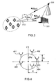
- the figure 1 shows that an antenna processing system comprises a network 102 of sensors receiving sources with different arrival angles ⁇ mp .
- the elementary sensors 101 of the network receive the sources E1, E2 with a phase and an amplitude depending on particular of their angles of incidence and the position of the sensors.
- the angles of incidence are parameterized in one dimension (1D) by the azimuth ⁇ m and in two dimensions (2D) by the azimuth ⁇ m and the elevation ⁇ m .
- a direction finding 1D is defined by techniques that estimate only the azimuth by assuming that the waves of the sources propagate in the plane 201 of the sensor array.
- the direction finding technique jointly estimates the azimuth and the elevation of a source, it is a question of 2D direction finding.
- Antenna processing techniques are intended in particular to exploit the spatial diversity generated by the multi-antenna reception of the incident signals, in other words, to use the position of the antennas of the network to make better use of the differences in incidence and distance of the sources.
- the figure 3 illustrates an application to direction finding in the presence of multipaths.
- the m -th source 301 propagates along paths P 311, 312, 313 incidences ⁇ mp (1 ⁇ p ⁇ P) which are caused by P -1 obstacles 320 in the radio environment.
- the problem addressed in the method according to the invention is, in particular, to perform a 2D direction finding for coherent paths where the deviation of propagation time between the direct path and a secondary path is very small.
- the algorithms for handling the case of coherent sources are the Maximum Likelihood algorithms [2] [3] that are applicable on any geometric sensor networks.
- these techniques require the calculation of a multidimensional criterion whose number of dimensions depends on the number of paths and the number of incidence parameters per path. More particularly in the presence of K paths, the criterion is 2 K dimensions for a 2D direction finding to jointly estimate all the incidences ( ⁇ 1 , ..., ⁇ K ) . It should be noted that even in the presence of a number K 'of coherent paths less than the total number K of paths, the calculation of the maximum likelihood criterion remains at 2 K dimensions.
- the first determined component w of the wave vectors is the projection, on the axis formed by the linear sub-network, of the projection of the wave vectors on the formed plane. by the sensor network.
- w p cos ( ⁇ p - ⁇ ).
- the direction finding algorithm used to determine the second component is the maximum likelihood algorithm.
- the network is disturbed by mutual coupling of known matrix Z
- the method comprises a coupling suppression step executed before the estimation steps of the values of the components w and u, said coupling removal step determining a noise-cleaned covariance matrix by applying the following processing to the covariance matrix: Z -1 (R x - ⁇ 2
- x n (t) is the signal at the output of the nth sensor
- N the number of sensors
- n ( t ) is the additive noise
- ⁇ is the azimuth
- elevation and ⁇ ⁇ mp, mp ⁇ , ⁇ mp are respectively the attenuation, the direction and the p th delay paths of the m -th source.
- Z is the coupling matrix
- ⁇ is the wavelength
- ( u, v ) are the coordinates of the wave vector in the plane of the antenna.
- a ( ⁇ m , ⁇ m , P m ) is the response of the sensor array to the mth source
- ⁇ m [ ⁇ m 1 ⁇ ⁇ mP ' m ] T
- ⁇ m [ ⁇ m 1 ⁇ ⁇ mP m ] T.
- the source vector of the source is no longer a ( ⁇ m 1 ) but a composite director vector a ( ⁇ m , ⁇ m , P m ) dependent on a larger number of parameters.
- a first MUSIC-coherent algorithm [4] is first presented.
- the expression of the matrix R x is the following from (4):
- R x AR s ⁇ AT H + ⁇ 2 ⁇ I NOT with ⁇
- the rank of the matrix R x is K.
- the NK eigenvectors e i ( K +1 ⁇ l ⁇ N ) associated with the lowest eigenvalues of R x are orthogonal to the vectors e k (1 k k ⁇ K ) of the expression (6) and define the noise space . Since the vectors e i and e k are orthogonal, the direction vectors a ( ⁇ ⁇ , ⁇ ⁇ , K i ) are orthogonal to the noise vectors e i .
- the coherent MUSIC method described in [4] aims to reduce the number of search parameters of the MUSIC criterion.
- J MUSIC - Coherent ⁇ det D ⁇ ⁇ H ⁇ b ⁇ D ⁇ det D ⁇ ⁇ H D ⁇
- det ( M ) is the determinant of matrix M.
- the MUSIC-coherent criterion remains four-dimensional for azimuth-elevation goniometry. More generally, the MUSIC-coherent method requires the calculation of a criterion (9) having 2 K max dimensions. However, the method makes no assumption on the geometry of the network because it does not require any constraint on the expression of the director vector a ( ⁇ ).
- R x E [ x ( t ) x ( t ) H ].
- This procedure aims to obtain a matrix R x SM having a rank higher than the R x i without destroying the structure of the signal space generated by A 1 .
- Spatial smoothing and Forward-Backward techniques can be combined to increase decorrelation capacity in number of trips. These smoothing techniques make it possible to process the coherent sources with computing power very close to the implementation of a single direction finding algorithm such as MUSIC.
- the figure 6 shows that a network composed of two sub-networks 601, 602 of four sensors contains at least seven sensors.
- This network also has the disadvantage of being weakly open (or has a small footprint space) because the four-sensor subnetworks must be unambiguous. Since the sub-networks are composed of four sensors, this ambiguity constraint requires an inter-sensor spacing of less than ⁇ / 2. Indeed, the more open a network is, the more accurate the arrival angles are estimated with a better robustness to calibration errors. In the case where it is desired to perform an azimuth goniometry only, the constraint C3 is no longer present and the network making it possible to perform a direction finding on two coherent sources composed of two subareas of four sensors is a linear network equi -space with five sensors.
- Each sub-network is then a linear network equi-spaced four sensors.
- the figure 7 shows that the linear subnetwork 701 which allows azimuth direction finding two coherent paths has the following differences with respect to the network 702 which makes it possible in azimuth-elevation: on the one hand, it is composed of fewer sensors: five instead of seven, on the other hand, it has a larger footprint: 4d instead of 3d knowing that d is a distance less than ⁇ / 2, where ⁇ is the wavelength of the transmitted signals.
- the decorrelation of two coherent paths for an azimuth-site direction finding requires a network of sensors having more sensors and less opening than the network making it possible to perform a direction finding in azimuth only.
- a linear network that is not necessarily equi-spaced is sufficient.
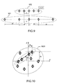
- the figure 9 shows that the Forward-Backward technique makes it possible, compared to the spatial smoothing technique, to perform unambiguous direction finding on two paths coherent with a network 901 having a larger aperture (10d instead of 4d for a network 902 used for spatial smoothing).
- the Forward-Backward technique has the advantage of not imposing a geometry constraint on half of the network. The other half of the network is symmetrical to the first half.
- the method according to the invention presented mixes the MUSIC method consistent with a Forward-Backward technique and / or spatial smoothing.
- the method contemplates using a sensor array containing a linear subnetwork on which a spatial and / or forward smoothing technique.
- -Backward is possible.
- the figure 10 shows such a network 1001 with a linear subnet 1002 having an orientation ⁇ with respect to the x-axis.
- the preceding steps show that the computation of a 2 K max dimension criterion for the MUSIC-coherent algorithm alone in 2D has been replaced by the computation of a MUSIC criterion with one dimension according to the parameter w and the cost of computation of the MUSIC-coherent criterion in 1 D with the variable u having K max dimensions.
- nb is large by being proportional to the size of the network ( nb > 50).
- u k is a consistent parameter vector for MUSIC when J MUSIC - Coherent u k ⁇ ⁇ K max where ⁇ (K max ) is a threshold between 0 and 1 because the criterion J MUSIC-Coherent ( u ) is normalized.
- ⁇ is a threshold between 0 and 1 because the criterion J MUSIC ( w ) is normalized.
- step B of the process can be applied several times.
- ⁇ i ⁇ ⁇ X i for 1 ⁇ i ⁇
- the number L as well as the sets ⁇ i can be determined by a conventional arithmetic process.
- An advantage of the method according to the invention is that the minimum number of sensors for estimating the direction of arrival of K coherent paths in 2D is lower than with prior art methods, which require a number of sensors greater than 2 (K + 1), the method according to the invention requires only a number of sensors greater than K.
- Another advantage of the method according to the invention is that it makes it possible to estimate directions of arrival of the 2D paths with larger networks, which improves the accuracy of the estimation.
Landscapes
- Physics & Mathematics (AREA)
- Engineering & Computer Science (AREA)
- General Physics & Mathematics (AREA)
- Radar, Positioning & Navigation (AREA)
- Remote Sensing (AREA)
- Measurement Of Velocity Or Position Using Acoustic Or Ultrasonic Waves (AREA)
- Radar Systems Or Details Thereof (AREA)
Claims (10)
- Verfahren zur gemeinsamen Bestimmung des Azimutwinkels θ und des Erhebungswinkels Δ der Wellenvektoren von P Wellen in eine System, das ein Sensornetzwerk (1001) umfasst, wobei sich mehrere Wellen von den P Wellen auf kohärenten Wegen zwischen einer Quelle und den Sensoren verbreiten, wobei das Verfahren dadurch gekennzeichnet ist, dass es mindestens die folgenden Schnitte umfasst:• Auswählen einer Untergruppe von Sensoren aus den Sensoren, um ein lineares Sensor-Unternetzwerk (1002) zu bilden,• Anwenden auf die Signale, die von dem ausgewählten Unternetzwerk ausgegeben werden, eines Algorithmus gemäß einer einzigen Dimension, um die Quellen der P Wellen zu dekorrelieren,• Bestimmen einer ersten Komponente w der Wellenvektoren durch Anwenden auf die auf den Sensoren des ausgewählten Unternetzwerks beobachteten Signale eines Goniometrie-Algorithmus gemäß der einzigen Dimension w,• Bestimmen einer zweiten Komponente u der Wellenvektoren durch Anwenden auf die Signale, die von der Gesamtheit des Sensornetzwerks ausgegeben werden, eines Goniometrie-Algorithmus gemäß der einzigen Dimension u,• Bestimmen von θ und Δ ausgehend von w und u.
- Verfahren nach Anspruch 1, dadurch gekennzeichnet, dass:• die Sensoren, die das Unternetzwerk bilden, derart ausgewählt werden, dass mindestens ein Teil des Unternetzwerks durch Translation invariant ist,• ein Raumglättungsalgorithmus angewendet wird, um die Quellen der P Wellen zu dekorrelieren.
- Verfahren nach Anspruch 1 oder 2, dadurch gekennzeichnet, dass:• die Sensoren, die das Unternetzwerk bilden, derart ausgewählt werden, dass mindestens ein Teil des Unternetzwerks ein Symmetriezentrum aufweist,• ein Forward-Backward-Algorithmus angewendet wird, um die Quellen der P Wellen zu dekorrelieren.
- Verfahren nach einem der Ansprüche 1, 2 oder 3, dadurch gekennzeichnet, dass die erste Komponente w, die von den Wellenvektoren bestimmt wird, die Projektion auf die von dem linearen Unternetzwerk gebildete Achse der Projektion der Wellenvektoren auf die von dem Sensornetzwerk gebildete Ebene ist.
- Verfahren nach einem der vorangehenden Ansprüche, dadurch gekennzeichnet, dass es mindestens die folgenden Schritte aufweist:• Berechnen der Kovarianzmatrix Rx über die Gesamtheit des Sensometzwerks,• Auslesen der Kovarianzmatrix Rx', die dem ausgewählten linearen Unternetzwerk entspricht, aus Rx,• Anwenden eines Dekorrelationsalgorithmus der Quellen auf Rx',• Ermitteln, für jeden Weg p, der Werte der ersten Komponente wp=cos(θp-α)·cos(Δp) durch Anwenden eines Goniometriealgorithmus in 1D auf die dekorrelierte Matrix Rx', wobei α der Azimut-Orientierungswinkel der von dem linearen Unternetzwerk gebildeten Achse ist,• Ermitteln der Werte der zweiten Komponente up = cos(θp). cos(Δp) für jeden Weg p durch Anwenden eines Goniometriealgorithmus in 1 D auf die Matrix Rx,• Bestimmen, ausgehen von den Werten der Paare (wp, up), der Werte der Paare Azimut-Erhebung (θp, Δp).
- Verfahren nach einem der vorangehenden Ansprüche, dadurch gekennzeichnet, dass der für die Bestimmung der ersten Komponente w jedes Wellenvektors P verwendete Goniometriealgorithmus der Algorithmus MUSIC ist, wobei das für die Bestimmung der Komponente w zu minimierende Kriterium JMUSIC gleich

wobei πb' der aus der dekorrelierten Kovarianzmatrix Rx', die dem ausgewählten linearen Unternetzwerk entspricht, ausgelesene Geräuschprojektor ist, und a(w)' die Antwort des ausgewählten Untemetzwerks auf die einfallenden Wellen P darstellt. - Verfahren nach einem der vorangehenden Ansprüche, dadurch gekennzeichnet, dass der für die Bestimmung der zweiten Komponente verwendete Goniometriealgorithmus der in einer einzigen Dimension MUSIC-kohärente Algorithmus ist, wobei das zu minimierende Kriterium ist:

wobei
wobei α der Azimut-Orientierungswinkel der von dem linearen Unternetzwerk gebildeten Achse ist, wobei D(Θ) ein Vektor gleich [a(Θ,) ... a(Θ kmax ) ] ist, wobei a(Θ,) die Antwort des Sensometzwerks auf den Weg mit den Index i ist, wobei Kmax die maximale Anzahl kohärenter Wege ist. - Verfahren nach einem der Ansprüche 1 bis 6, dadurch gekennzeichnet, dass der zur Bestimmung der zweiten Komponente verwendete Goniometriealgorithmus der Algorithmus des Wahrscheinlichkeitsmaximums ist.
- Verfahren nach einem der Ansprüche 5 bis 8, wobei das Netzwerk durch gegenseitige Kopplung einer bekannten Matrix Z gestört wird, wobei das Verfahren dadurch gekennzeichnet ist, dass es einen Schritt der Unterdrückung der Kopplung aufweist, der vor den Schritten der Ermittlung der Werte der Komponenten w und u durchgerührt wird, wobei der Schritt der Unterdrückung der Kopplung eine geräuschbereinigte Kovarianzmatrix bestimmt durch Anwendung der folgenden Behandlung auf die Kovarianzmatrix: Z-1(Rx-σ2|)Z-11, wobei σ2 das ermittelte Geräuschniveau ist.
- Verfahren nach einem der Ansprüche 5 bis 9, dadurch gekennzeichnet, dass die Bestimmung der Wertepaare (θp, Δp) ausgehend von den Wertepaaren (wp, up) wie folgt durchgeführt wird:

wobei
Applications Claiming Priority (2)
| Application Number | Priority Date | Filing Date | Title |
|---|---|---|---|
| FR0807404A FR2940461B1 (fr) | 2008-12-23 | 2008-12-23 | Procede de determination des angles d'arrivee en azimut et en elevation de sources coherentes |
| PCT/EP2009/065663 WO2010072494A1 (fr) | 2008-12-23 | 2009-11-23 | Procede de determination des angles d'arrivee en azimut et en elevation de sources coherentes |
Publications (2)
| Publication Number | Publication Date |
|---|---|
| EP2368129A1 EP2368129A1 (de) | 2011-09-28 |
| EP2368129B1 true EP2368129B1 (de) | 2013-05-22 |
Family
ID=41110496
Family Applications (1)
| Application Number | Title | Priority Date | Filing Date |
|---|---|---|---|
| EP09760837.6A Active EP2368129B1 (de) | 2008-12-23 | 2009-11-23 | Verfahren zur bestimmung von azimuth- und erhebungswinkeln der ankunft kohärenter quellen |
Country Status (5)
| Country | Link |
|---|---|
| US (1) | US8669901B2 (de) |
| EP (1) | EP2368129B1 (de) |
| CN (1) | CN102317808B (de) |
| FR (1) | FR2940461B1 (de) |
| WO (1) | WO2010072494A1 (de) |
Families Citing this family (17)
| Publication number | Priority date | Publication date | Assignee | Title |
|---|---|---|---|---|
| RU2460084C1 (ru) * | 2011-07-29 | 2012-08-27 | Александр Абрамович Часовской | Устройство обработки радиолокационных сигналов |
| CN102385048A (zh) * | 2011-08-10 | 2012-03-21 | 西安交通大学 | 基于均匀线阵的混合信号方向估计方法 |
| FR2985036B1 (fr) * | 2011-12-22 | 2014-01-17 | Thales Sa | Procede de localisation de sources emettrices par exploitation du couplage mutuel d'un reseau antennaire de petite base et systeme recepteur mono-voie a commutation lente mettant en oeuvre le procede |
| FR2985037B1 (fr) * | 2011-12-22 | 2014-01-17 | Thales Sa | Procede de localisation de sources emettrices par exploitation du couplage mutuel d'un reseau antennaire de petite base et systeme recepteur mono-voie a communication rapide mettant en oeuvre le procede |
| US9759807B2 (en) * | 2013-10-25 | 2017-09-12 | Texas Instruments Incorporated | Techniques for angle resolution in radar |
| US10359511B2 (en) | 2014-12-29 | 2019-07-23 | Sony Corporation | Surveillance apparatus having a radar sensor |
| GB2563834A (en) | 2017-06-23 | 2019-01-02 | Decawave Ltd | Wideband antenna array |
| CN107884758B (zh) * | 2017-09-28 | 2019-10-18 | 北京华航无线电测量研究所 | 一种面向主动相控阵雷达的解相干谱估计方法 |
| CN108680891B (zh) * | 2018-01-05 | 2022-02-22 | 大连大学 | 非均匀噪声条件下考虑互耦效应的doa估计方法 |
| CN108983145A (zh) * | 2018-08-27 | 2018-12-11 | 西安电子科技大学 | 电磁矢量传感器阵列宽带相干源定位方法 |
| CN109901101A (zh) * | 2019-02-25 | 2019-06-18 | 西安电子科技大学 | 基于电磁矢量传感器互质阵列相干信号到达角估计方法 |
| CN112230194B (zh) * | 2020-08-05 | 2024-01-26 | 北京航空航天大学杭州创新研究院 | 一种基于平移阵列的解模糊方法、设备及存储介质 |
| CN111948599B (zh) * | 2020-08-14 | 2022-08-19 | 电子科技大学 | 一种角度相关互耦影响下相干信号的高分辨率定位方法 |
| CN116047591B (zh) * | 2021-10-28 | 2026-03-17 | 中国石油化工股份有限公司 | 基于宽带线阵波束形成的地震相干噪声压制方法及装置 |
| CN114994593B (zh) * | 2022-05-25 | 2024-05-31 | 成都华日通讯技术股份有限公司 | 一种基于测向设备分析信号相干关系的方法 |
| CN115267656B (zh) * | 2022-08-19 | 2024-11-15 | 河北阿卡斯物联网科技有限公司 | 一种测量蓝牙信号达到角的方法及系统 |
| CN118584469B (zh) * | 2024-08-02 | 2024-10-01 | 长沙莫之比智能科技有限公司 | 一种基于置信度加权的毫米波雷达远距离目标测角方法 |
Family Cites Families (5)
| Publication number | Priority date | Publication date | Assignee | Title |
|---|---|---|---|---|
| SE511504C2 (sv) * | 1997-10-17 | 1999-10-11 | Apogeum Ab | Sätt och anordning för associering av anonyma reflektorer till detekterade vinkellägen |
| FR2872350B1 (fr) * | 2004-06-25 | 2006-12-22 | Thales Sa | Procede de goniometrie multi-parametres par separation de l'incidence et des parametres de nuisances |
| EP1846778B1 (de) * | 2005-02-01 | 2008-10-29 | Thales | 1d- oder 2d-goniometrieverfahren diffuser quellen |
| FR2917180B1 (fr) * | 2007-06-08 | 2010-05-14 | Thales Sa | Procede d'estimation des angles d'arrivees de sources coherentes par une technique de lissage spatial sur un reseau de capteurs quelconque |
| US8133182B2 (en) * | 2008-09-09 | 2012-03-13 | Siemens Medical Solutions Usa, Inc. | Multi-dimensional transducer array and beamforming for ultrasound imaging |
-
2008
- 2008-12-23 FR FR0807404A patent/FR2940461B1/fr not_active Expired - Fee Related
-
2009
- 2009-11-23 US US13/141,968 patent/US8669901B2/en not_active Expired - Fee Related
- 2009-11-23 WO PCT/EP2009/065663 patent/WO2010072494A1/fr not_active Ceased
- 2009-11-23 CN CN200980156714.9A patent/CN102317808B/zh not_active Expired - Fee Related
- 2009-11-23 EP EP09760837.6A patent/EP2368129B1/de active Active
Also Published As
| Publication number | Publication date |
|---|---|
| CN102317808B (zh) | 2014-02-19 |
| US20120098703A1 (en) | 2012-04-26 |
| EP2368129A1 (de) | 2011-09-28 |
| FR2940461B1 (fr) | 2011-01-21 |
| FR2940461A1 (fr) | 2010-06-25 |
| US8669901B2 (en) | 2014-03-11 |
| WO2010072494A1 (fr) | 2010-07-01 |
| CN102317808A (zh) | 2012-01-11 |
Similar Documents
| Publication | Publication Date | Title |
|---|---|---|
| EP2368129B1 (de) | Verfahren zur bestimmung von azimuth- und erhebungswinkeln der ankunft kohärenter quellen | |
| EP1759435B1 (de) | Multiparametrisches richtungsfindungsverfahren mit trennung von ereignis- und störungsparametern | |
| EP1259833B1 (de) | Verfahren zum orten von funkquellen mittels eines hochauflösenden zweikanaligen funkpeilers | |
| Tirer et al. | High resolution direct position determination of radio frequency sources | |
| EP2215492B1 (de) | Verfahren zur mehrsender- und mehrwege-aoa-tdoa-lokalisierung, mit einem subverfahren zum synchronisieren und entzerren der empfangsstationen | |
| EP2579063B1 (de) | Verfahren und System zur Lokalisierung von Interferenzen durch Frequenz-Subbasisband | |
| US8428897B2 (en) | Method and apparatus for spectral cross coherence | |
| EP2428810B1 (de) | Geo-Lokalisierungsverfahren mit mehreren Sender mit räumlich-zeitlicher Behandlung | |
| FR2917180A1 (fr) | Procede d'estimation des angles d'arrivees de sources coherentes par une technique de lissage spatial sur un reseau de capteurs quelconque | |
| EP2523020A1 (de) | Intereferenz-Lokalisierungsverfahren und -system, das ein Satellitennavigationssignal zuordnet | |
| EP3281026B1 (de) | Verfahren zur trennung von quellen für spärliche signale | |
| EP2517037B1 (de) | Verfahren zur kalkulation der anzahl von störquellen einer sensoranordnung mittels kalkulation von rauschstatistiken | |
| Park et al. | Maximum‐likelihood angle estimator for multi‐channel FM‐radio‐based passive coherent location | |
| EP1582888B1 (de) | Verfahren zur breitbandigen blinden Ortung von einem oder mehreren Sendern durch einen sich vorbeibewegenden Träger | |
| EP1682923B1 (de) | Verfahren zum lokalisieren mindestens eines emitters | |
| EP1253435B1 (de) | Verfahren und Vorrichtung zur Raum-Zeitschätzung von einem oder mehrerer Sendern | |
| Tirer et al. | A method for reducing the performance gap between non-coherent and coherent sub-arrays | |
| EP1846778A1 (de) | 1d- oder 2d-goniometrieverfahren diffuser quellen | |
| EP1291664B1 (de) | Verfahren und Vorrichtung zur kooperativen Funkpeilung im Übertragungsmodus | |
| Wang et al. | Snapshot-deficient active target localization in beam-time domain using multi-frequency expectation-maximization algorithm | |
| EP2458398A2 (de) | Verfahren zur Optimierung eines Netzes aus heterogenen Sensoren für die Goniometrie | |
| Kaouri et al. | Determining the probability of correct resolution of the left–right ambiguity in towed array sonar | |
| Wang et al. | Root-MUSIC algorithm with real-valued eigendecomposition for acoustic vector sensor array | |
| Karim et al. | A new improved algorithm for low complexity wideband angle of arrival estimation | |
| EP2857856B1 (de) | Goniometrieverfahren mit einem System, das über weniger Empfangswege als Sensoren verfügt |
Legal Events
| Date | Code | Title | Description |
|---|---|---|---|
| PUAI | Public reference made under article 153(3) epc to a published international application that has entered the european phase |
Free format text: ORIGINAL CODE: 0009012 |
|
| 17P | Request for examination filed |
Effective date: 20110623 |
|
| AK | Designated contracting states |
Kind code of ref document: A1 Designated state(s): AT BE BG CH CY CZ DE DK EE ES FI FR GB GR HR HU IE IS IT LI LT LU LV MC MK MT NL NO PL PT RO SE SI SK SM TR |
|
| DAX | Request for extension of the european patent (deleted) | ||
| GRAP | Despatch of communication of intention to grant a patent |
Free format text: ORIGINAL CODE: EPIDOSNIGR1 |
|
| GRAS | Grant fee paid |
Free format text: ORIGINAL CODE: EPIDOSNIGR3 |
|
| GRAA | (expected) grant |
Free format text: ORIGINAL CODE: 0009210 |
|
| AK | Designated contracting states |
Kind code of ref document: B1 Designated state(s): AT BE BG CH CY CZ DE DK EE ES FI FR GB GR HR HU IE IS IT LI LT LU LV MC MK MT NL NO PL PT RO SE SI SK SM TR |
|
| REG | Reference to a national code |
Ref country code: GB Ref legal event code: FG4D Free format text: NOT ENGLISH |
|
| REG | Reference to a national code |
Ref country code: CH Ref legal event code: EP |
|
| REG | Reference to a national code |
Ref country code: AT Ref legal event code: REF Ref document number: 613501 Country of ref document: AT Kind code of ref document: T Effective date: 20130615 |
|
| REG | Reference to a national code |
Ref country code: IE Ref legal event code: FG4D Free format text: LANGUAGE OF EP DOCUMENT: FRENCH |
|
| REG | Reference to a national code |
Ref country code: DE Ref legal event code: R096 Ref document number: 602009015925 Country of ref document: DE Effective date: 20130718 |
|
| REG | Reference to a national code |
Ref country code: AT Ref legal event code: MK05 Ref document number: 613501 Country of ref document: AT Kind code of ref document: T Effective date: 20130522 |
|
| REG | Reference to a national code |
Ref country code: LT Ref legal event code: MG4D |
|
| PG25 | Lapsed in a contracting state [announced via postgrant information from national office to epo] |
Ref country code: PT Free format text: LAPSE BECAUSE OF FAILURE TO SUBMIT A TRANSLATION OF THE DESCRIPTION OR TO PAY THE FEE WITHIN THE PRESCRIBED TIME-LIMIT Effective date: 20130923 Ref country code: ES Free format text: LAPSE BECAUSE OF FAILURE TO SUBMIT A TRANSLATION OF THE DESCRIPTION OR TO PAY THE FEE WITHIN THE PRESCRIBED TIME-LIMIT Effective date: 20130902 Ref country code: SI Free format text: LAPSE BECAUSE OF FAILURE TO SUBMIT A TRANSLATION OF THE DESCRIPTION OR TO PAY THE FEE WITHIN THE PRESCRIBED TIME-LIMIT Effective date: 20130522 Ref country code: LT Free format text: LAPSE BECAUSE OF FAILURE TO SUBMIT A TRANSLATION OF THE DESCRIPTION OR TO PAY THE FEE WITHIN THE PRESCRIBED TIME-LIMIT Effective date: 20130522 Ref country code: AT Free format text: LAPSE BECAUSE OF FAILURE TO SUBMIT A TRANSLATION OF THE DESCRIPTION OR TO PAY THE FEE WITHIN THE PRESCRIBED TIME-LIMIT Effective date: 20130522 Ref country code: SE Free format text: LAPSE BECAUSE OF FAILURE TO SUBMIT A TRANSLATION OF THE DESCRIPTION OR TO PAY THE FEE WITHIN THE PRESCRIBED TIME-LIMIT Effective date: 20130522 Ref country code: IS Free format text: LAPSE BECAUSE OF FAILURE TO SUBMIT A TRANSLATION OF THE DESCRIPTION OR TO PAY THE FEE WITHIN THE PRESCRIBED TIME-LIMIT Effective date: 20130922 Ref country code: FI Free format text: LAPSE BECAUSE OF FAILURE TO SUBMIT A TRANSLATION OF THE DESCRIPTION OR TO PAY THE FEE WITHIN THE PRESCRIBED TIME-LIMIT Effective date: 20130522 Ref country code: GR Free format text: LAPSE BECAUSE OF FAILURE TO SUBMIT A TRANSLATION OF THE DESCRIPTION OR TO PAY THE FEE WITHIN THE PRESCRIBED TIME-LIMIT Effective date: 20130823 Ref country code: NO Free format text: LAPSE BECAUSE OF FAILURE TO SUBMIT A TRANSLATION OF THE DESCRIPTION OR TO PAY THE FEE WITHIN THE PRESCRIBED TIME-LIMIT Effective date: 20130822 |
|
| REG | Reference to a national code |
Ref country code: NL Ref legal event code: VDEP Effective date: 20130522 |
|
| PG25 | Lapsed in a contracting state [announced via postgrant information from national office to epo] |
Ref country code: BG Free format text: LAPSE BECAUSE OF FAILURE TO SUBMIT A TRANSLATION OF THE DESCRIPTION OR TO PAY THE FEE WITHIN THE PRESCRIBED TIME-LIMIT Effective date: 20130822 Ref country code: PL Free format text: LAPSE BECAUSE OF FAILURE TO SUBMIT A TRANSLATION OF THE DESCRIPTION OR TO PAY THE FEE WITHIN THE PRESCRIBED TIME-LIMIT Effective date: 20130522 Ref country code: HR Free format text: LAPSE BECAUSE OF FAILURE TO SUBMIT A TRANSLATION OF THE DESCRIPTION OR TO PAY THE FEE WITHIN THE PRESCRIBED TIME-LIMIT Effective date: 20130522 |
|
| PG25 | Lapsed in a contracting state [announced via postgrant information from national office to epo] |
Ref country code: LV Free format text: LAPSE BECAUSE OF FAILURE TO SUBMIT A TRANSLATION OF THE DESCRIPTION OR TO PAY THE FEE WITHIN THE PRESCRIBED TIME-LIMIT Effective date: 20130522 |
|
| PG25 | Lapsed in a contracting state [announced via postgrant information from national office to epo] |
Ref country code: DK Free format text: LAPSE BECAUSE OF FAILURE TO SUBMIT A TRANSLATION OF THE DESCRIPTION OR TO PAY THE FEE WITHIN THE PRESCRIBED TIME-LIMIT Effective date: 20130522 Ref country code: SK Free format text: LAPSE BECAUSE OF FAILURE TO SUBMIT A TRANSLATION OF THE DESCRIPTION OR TO PAY THE FEE WITHIN THE PRESCRIBED TIME-LIMIT Effective date: 20130522 Ref country code: CZ Free format text: LAPSE BECAUSE OF FAILURE TO SUBMIT A TRANSLATION OF THE DESCRIPTION OR TO PAY THE FEE WITHIN THE PRESCRIBED TIME-LIMIT Effective date: 20130522 Ref country code: EE Free format text: LAPSE BECAUSE OF FAILURE TO SUBMIT A TRANSLATION OF THE DESCRIPTION OR TO PAY THE FEE WITHIN THE PRESCRIBED TIME-LIMIT Effective date: 20130522 |
|
| PG25 | Lapsed in a contracting state [announced via postgrant information from national office to epo] |
Ref country code: IT Free format text: LAPSE BECAUSE OF FAILURE TO SUBMIT A TRANSLATION OF THE DESCRIPTION OR TO PAY THE FEE WITHIN THE PRESCRIBED TIME-LIMIT Effective date: 20130522 Ref country code: RO Free format text: LAPSE BECAUSE OF FAILURE TO SUBMIT A TRANSLATION OF THE DESCRIPTION OR TO PAY THE FEE WITHIN THE PRESCRIBED TIME-LIMIT Effective date: 20130522 Ref country code: NL Free format text: LAPSE BECAUSE OF FAILURE TO SUBMIT A TRANSLATION OF THE DESCRIPTION OR TO PAY THE FEE WITHIN THE PRESCRIBED TIME-LIMIT Effective date: 20130522 |
|
| PLBE | No opposition filed within time limit |
Free format text: ORIGINAL CODE: 0009261 |
|
| STAA | Information on the status of an ep patent application or granted ep patent |
Free format text: STATUS: NO OPPOSITION FILED WITHIN TIME LIMIT |
|
| 26N | No opposition filed |
Effective date: 20140225 |
|
| BERE | Be: lapsed |
Owner name: THALES Effective date: 20131130 |
|
| REG | Reference to a national code |
Ref country code: DE Ref legal event code: R097 Ref document number: 602009015925 Country of ref document: DE Effective date: 20140225 |
|
| REG | Reference to a national code |
Ref country code: CH Ref legal event code: PL |
|
| PG25 | Lapsed in a contracting state [announced via postgrant information from national office to epo] |
Ref country code: LI Free format text: LAPSE BECAUSE OF NON-PAYMENT OF DUE FEES Effective date: 20131130 Ref country code: MC Free format text: LAPSE BECAUSE OF FAILURE TO SUBMIT A TRANSLATION OF THE DESCRIPTION OR TO PAY THE FEE WITHIN THE PRESCRIBED TIME-LIMIT Effective date: 20130522 Ref country code: CH Free format text: LAPSE BECAUSE OF NON-PAYMENT OF DUE FEES Effective date: 20131130 |
|
| REG | Reference to a national code |
Ref country code: IE Ref legal event code: MM4A |
|
| PG25 | Lapsed in a contracting state [announced via postgrant information from national office to epo] |
Ref country code: BE Free format text: LAPSE BECAUSE OF NON-PAYMENT OF DUE FEES Effective date: 20131130 |
|
| PG25 | Lapsed in a contracting state [announced via postgrant information from national office to epo] |
Ref country code: IE Free format text: LAPSE BECAUSE OF NON-PAYMENT OF DUE FEES Effective date: 20131123 |
|
| PG25 | Lapsed in a contracting state [announced via postgrant information from national office to epo] |
Ref country code: SM Free format text: LAPSE BECAUSE OF FAILURE TO SUBMIT A TRANSLATION OF THE DESCRIPTION OR TO PAY THE FEE WITHIN THE PRESCRIBED TIME-LIMIT Effective date: 20130522 |
|
| PG25 | Lapsed in a contracting state [announced via postgrant information from national office to epo] |
Ref country code: TR Free format text: LAPSE BECAUSE OF FAILURE TO SUBMIT A TRANSLATION OF THE DESCRIPTION OR TO PAY THE FEE WITHIN THE PRESCRIBED TIME-LIMIT Effective date: 20130522 Ref country code: CY Free format text: LAPSE BECAUSE OF FAILURE TO SUBMIT A TRANSLATION OF THE DESCRIPTION OR TO PAY THE FEE WITHIN THE PRESCRIBED TIME-LIMIT Effective date: 20130522 |
|
| PG25 | Lapsed in a contracting state [announced via postgrant information from national office to epo] |
Ref country code: MK Free format text: LAPSE BECAUSE OF FAILURE TO SUBMIT A TRANSLATION OF THE DESCRIPTION OR TO PAY THE FEE WITHIN THE PRESCRIBED TIME-LIMIT Effective date: 20130522 Ref country code: LU Free format text: LAPSE BECAUSE OF NON-PAYMENT OF DUE FEES Effective date: 20131123 Ref country code: HU Free format text: LAPSE BECAUSE OF FAILURE TO SUBMIT A TRANSLATION OF THE DESCRIPTION OR TO PAY THE FEE WITHIN THE PRESCRIBED TIME-LIMIT; INVALID AB INITIO Effective date: 20091123 |
|
| PG25 | Lapsed in a contracting state [announced via postgrant information from national office to epo] |
Ref country code: MT Free format text: LAPSE BECAUSE OF FAILURE TO SUBMIT A TRANSLATION OF THE DESCRIPTION OR TO PAY THE FEE WITHIN THE PRESCRIBED TIME-LIMIT Effective date: 20130522 |
|
| REG | Reference to a national code |
Ref country code: FR Ref legal event code: PLFP Year of fee payment: 7 |
|
| REG | Reference to a national code |
Ref country code: FR Ref legal event code: PLFP Year of fee payment: 8 |
|
| REG | Reference to a national code |
Ref country code: FR Ref legal event code: PLFP Year of fee payment: 9 |
|
| REG | Reference to a national code |
Ref country code: FR Ref legal event code: PLFP Year of fee payment: 10 |
|
| PGFP | Annual fee paid to national office [announced via postgrant information from national office to epo] |
Ref country code: GB Payment date: 20191113 Year of fee payment: 11 |
|
| GBPC | Gb: european patent ceased through non-payment of renewal fee |
Effective date: 20201123 |
|
| PG25 | Lapsed in a contracting state [announced via postgrant information from national office to epo] |
Ref country code: GB Free format text: LAPSE BECAUSE OF NON-PAYMENT OF DUE FEES Effective date: 20201123 |
|
| P01 | Opt-out of the competence of the unified patent court (upc) registered |
Effective date: 20230517 |
|
| PGFP | Annual fee paid to national office [announced via postgrant information from national office to epo] |
Ref country code: DE Payment date: 20251014 Year of fee payment: 17 |
|
| PGFP | Annual fee paid to national office [announced via postgrant information from national office to epo] |
Ref country code: FR Payment date: 20251023 Year of fee payment: 17 |