EP2368302B1 - Bogenfehler-unterbrecherschalter und verfahren zur gewährleistung von verbesserter zurückweisung von falschen auslösungen - Google Patents
Bogenfehler-unterbrecherschalter und verfahren zur gewährleistung von verbesserter zurückweisung von falschen auslösungen Download PDFInfo
- Publication number
- EP2368302B1 EP2368302B1 EP09805821.7A EP09805821A EP2368302B1 EP 2368302 B1 EP2368302 B1 EP 2368302B1 EP 09805821 A EP09805821 A EP 09805821A EP 2368302 B1 EP2368302 B1 EP 2368302B1
- Authority
- EP
- European Patent Office
- Prior art keywords
- minimum
- cycles
- value
- output
- predetermined value
- Prior art date
- Legal status (The legal status is an assumption and is not a legal conclusion. Google has not performed a legal analysis and makes no representation as to the accuracy of the status listed.)
- Active
Links
Images




Classifications
-
- H—ELECTRICITY
- H02—GENERATION; CONVERSION OR DISTRIBUTION OF ELECTRIC POWER
- H02H—EMERGENCY PROTECTIVE CIRCUIT ARRANGEMENTS
- H02H1/00—Details of emergency protective circuit arrangements
- H02H1/0007—Details of emergency protective circuit arrangements concerning the detecting means
- H02H1/0015—Using arc detectors
-
- H—ELECTRICITY
- H02—GENERATION; CONVERSION OR DISTRIBUTION OF ELECTRIC POWER
- H02H—EMERGENCY PROTECTIVE CIRCUIT ARRANGEMENTS
- H02H1/00—Details of emergency protective circuit arrangements
- H02H1/0092—Details of emergency protective circuit arrangements concerning the data processing means, e.g. expert systems, neural networks
Definitions
- the disclosed concept pertains generally to circuit interrupters and, more particularly, to arc fault circuit interrupters.
- the disclosed concept also pertains to methods of detecting arc faults.
- Circuit breakers are used to protect electrical circuitry from damage due to an overcurrent condition, such as an overload condition or a relatively high level short circuit or fault condition.
- an overcurrent condition such as an overload condition or a relatively high level short circuit or fault condition.
- small circuit breakers commonly referred to as miniature circuit breakers, used for residential and light commercial applications, such protection is typically provided by a thermal-magnetic trip device.
- This trip device includes a bimetal, which heats and bends in response to a persistent overcurrent condition. The bimetal, in turn, unlatches a spring powered operating mechanism, which opens the separable contacts of the circuit breaker to interrupt current flow in the protected power system.
- An arc fault circuit interrupter is a device intended to mitigate the effects of arc faults by functioning to deenergize an electrical circuit when an arc fault is detected.
- AFCIs include: (1) arc fault circuit breakers; (2) branch/feeder arc fault circuit interrupters, which are intended to be installed at the origin of a branch circuit or feeder, such as a panelboard, and which may provide protection from series arc faults, ground faults and line-to-neutral faults up to the outlet; (3) outlet circuit arc fault circuit interrupters, which are intended to be installed at a branch circuit outlet, such as an outlet box, in order to provide protection of cord sets and power-supply cords connected to it (when provided with receptacle outlets) against the unwanted effects of arcing, and which may provide protection from series arc faults, line-to-ground faults and line-to-neutral faults; (4) cord arc fault circuit interrupters, which are intended to be connected to a receptacle outlet, in order to provide protection to an integral
- Arc faults can be series or parallel. Examples of a series arc are a broken wire where the ends of the broken wire are close enough to cause arcing, or a relatively poor electrical connection. Parallel arcs occur between conductors of different potential including, for example, a power conductor and a ground. Unlike a parallel arc fault, series arc faults do not usually create an increase in current since the fault is in series with the load. In fact, a series arc fault may result in a slight reduction in load current and not be detected by the normal overload and overcurrent protection of conventional protection devices.
- Both safe and unsafe series arcs occur in power circuits, such as electrical power distribution systems (or electrical distribution systems).
- One example of safe series arcs occurs in the commutator brushes of direct current (DC) and universal motors.
- DC direct current
- universal motors are designed to minimize the net duration and thereby the total energy dissipated by commutation arcing.
- the materials and physical shape of the commutator brushes are chosen, in order that they are minimally affected by the arcing.
- the series arcs that occur in universal motors are intended and perform a constructive purpose.
- Arcs that safely occur within universal motors and unsafe series arcs that happen by random chance are the exact same physical phenomena; however, one occurs by design and creates a benefit while the other is unintended and may be destructive.
- circuit interrupters that accurately distinguish between safe series arcing (e.g., without limitation, in universal motors) and unintended, potentially hazardous series arcs, and trip in response to only the latter. This need is further compounded by the reality that, of all series arcs in power distribution systems, only a fraction are the unintended, unsafe variety.
- US 2008 106 832 A1 is directed toward a system and a method for detecting arc faults on a power line.
- the method may include monitoring power signals associated with a power line and filtering the power signals to produce a high frequency signal and a low frequency signal.
- a mask signal may generated based on the low frequency signal, and the high frequency signal may be analyzed to extract a broadband portion of the high frequency signal.
- a fault counter may be incremented if the magnitude of the broadband portion is approximately greater than a first threshold level.
- a fault counter may be decremented if the magnitude of the broadband portion is approximately less than the first threshold level.
- a trip signal is provided to a switching device associated with the power line if the fault counter exceeds a predetermined fault limit.
- an arc fault circuit interrupter as set forth in claim 1 and methods of detecting an arc fault condition as set forth in claims 12 and 13 are provided. Further embodiments are inter alia disclosed in the dependent claims.
- the arc fault circuit interrupter inter alia comprises: separable contacts; an operating mechanism structured to open and close the separable contacts; an arc fault detector structured to detect an arc fault condition operatively associated with the separable contacts, the arc fault detector comprising: a tuned current sensor structured to sense broadband noise of a current flowing through the separable contacts, a compression circuit including an input of the sensed broadband noise from the tuned current sensor and an output, the compression circuit being structured to compress the dynamic range of the sensed broadband noise, a minimum detector including an input of the output of the compression circuit and an output of the minimum value of the input of the minimum detector, and a processor including a number of inputs and an output, one of the number of inputs being the output of the minimum value of the minimum detector; and a trip mechanism
- the processor may be structured to input the output of the minimum detector synchronous with an alternating current half-cycle, compare a profile of the output of the minimum detector versus phase angle of the alternating current half-cycle against a plurality of profiles operatively associated with series arcs, and determine whether each alternating current half-cycle corresponds to one of the plurality of profiles.
- the arc fault detector may comprise a zero crossing detector structured to synchronize the processor with a plurality of line half-cycles.
- the processor may comprise an analog-to-digital converter structured to input and convert the output of the minimum detector, and a routine structured to input and reset the output of the minimum detector a plurality of times for each of the line half-cycles.
- the output of the minimum detector may be proportional to the minimum of the logarithm of the envelope of the sensed broadband noise; the output of the minimum detector may be structured to increase in response to continuous broadband noise from the arc fault condition; and the output of the minimum detector may be structured to not increase in response to non-continuous broadband noise.
- a method of detecting an arc fault condition of an alternating current power circuit having a plurality of half-cycles comprises: sensing broadband noise of a current flowing in the power circuit; compressing the dynamic range of the sensed broadband noise; detecting a minimum of the compressed and sensed broadband noise for a plurality of samples for each of the half-cycles; determining a minimum value from the minimum of the compressed and sensed broadband noise for the samples for each of the half-cycles; determining a maximum value from the minimum of the compressed and sensed broadband noise for the samples for each of the half-cycles; determining a dynamic range value from the difference between the maximum value and the minimum value; determining a count of a number of the samples that exceed a first predetermined value for each of the line half-cycles; determining a condition defined by: (a) the dynamic range value being greater than a second predetermined value, (b) the minimum value occurs at one of either a plurality of the samples at the beginning of a corresponding one of the line
- a method of detecting an arc fault condition of an alternating current power circuit having a plurality of half-cycles comprises: sensing broadband noise of a current flowing in the power circuit; compressing the dynamic range of the sensed broadband noise; detecting a minimum of the compressed and sensed broadband noise for a plurality of samples for each of the half-cycles; determining a minimum value from the minimum of the compressed and sensed broadband noise for the samples for each of the half-cycles; determining a maximum value from the minimum of the compressed and sensed broadband noise for the samples for each of the half-cycles; determining a dynamic range value from the difference between the maximum value and the minimum value; determining a maximum difference between subsequent values from the minimum of the compressed and sensed broadband noise for each of the line half-cycles; determining a count of a number of the minimum of the compressed and sensed broadband noise that are less than a first predetermined value for each of the line half-cycles plus a number of the minimum of the compressed and sensed broadband noise that
- number shall mean one or an integer greater than one ( i . e ., a plurality).
- processor means a programmable analog and/or digital device that can store, retrieve, and process data; a computer; a workstation; a personal computer; a microprocessor; a microcontroller; a microcomputer; a central processing unit; a mainframe computer; a mini-computer; a server; a networked processor; or any suitable processing device or apparatus.
- the term "tuned current sensor” means a current sensor (e.g., without limitation, a current transformer) structured to sense broadband noise of a current at a predefined frequency or a predefined range of frequencies. Such predefined frequency or frequencies are substantially greater than a corresponding line frequency (e.g., without limitation, 60 Hz).
- the range of frequencies can, for example, be fixed or can be dynamically changed (e.g., without limitation, by a processor).
- dynamic range means the ratio or difference between the smallest and largest possible values of a changeable quantity (e.g., without limitation, amplitude; magnitude).
- compression circuit means a circuit structured to compress the dynamic range of a signal.
- dynamic range compression or compression reduces the dynamic range of a signal.
- a non-limiting example of a compression circuit is a demodulating (e.g., a logarithmic function is applied to the envelope of the output signal of a sensor, where the envelope is produced by a demodulator or other suitable amplitude modulation receiver) logarithmic amplifier structured to rectify a signal and perform a logarithmic conversion on the amplitude of a filtered version of such rectified signal.
- the disclosed concept is described in association with a single pole arc fault circuit interrupter (AFCI) 50, although the disclosed concept is applicable to AFCIs having any number of poles.
- AFCI arc fault circuit interrupter
- Commutation arcs in motors consist of a series of discretely spaced, very short-lived arcs, which strike and quench repeatedly throughout each half-cycle. These arcs are manifested by a series of discretely spaced, very short-lived bursts of broadband noise on the power line.
- loads with power electronics produce broadband noise as a result of current commutation in switching devices.
- These commutation events are also manifested by a series of discretely spaced, very short-lived bursts of broadband noise on the power line.
- Series arcs which consist of relatively many brief pulses whose net conduction time is relatively small compared to the half-cycle period of the source voltage dissipate much less energy than series arcs which are continuous and persist over a sizable fraction of each half-cycle.
- Typical broadband noise signatures produced by universal motor commutation and power electronic switching are shown in Figures 1 and 2 , respectively.
- the plot 2 of Figure 1 is produced using a suitable handheld sander (not shown) and demonstrates the discrete nature of power line noise produced by motor commutation.
- the plot 2 includes the logarithm of demodulated broadband power line noise 10.
- the plot 12 of Figure 2 is produced using a vacuum sweeper (not shown) and demonstrates the discrete nature of power line noise produced by power electronic switching.
- the plot 12 includes the logarithm of demodulated broadband power line noise 20.
- hazardous series arcs e.g., without limitation, those resulting from the test procedures of UL 1699
- hazardous series arcs are believed to strike and quench once per half-cycle, and to persist throughout a substantial portion of each half-cycle.
- hazardous series arcs are believed to be uniquely indicated by continuous, relatively long-lived bursts of broadband noise that persist for a substantial portion of each half-cycle.
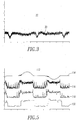
- a typical broadband noise signature produced by a series arc is shown by the plot 22 of Figure 3 .
- the broadband noise signature is produced by an arc in series with a 5 A resistor (not shown), generated using an opposing electrode arc generator (not shown) specified by UL1699.
- This demonstrates the continuous nature of power line noise produced by series arcing.
- the plot 22 includes the logarithm of demodulated broadband power line noise 30.
- the AFCI 50 includes separable contacts 52, an operating mechanism 54 structured to open and close the separable contacts 52 and an arc fault detector 56 structured to detect an arc fault condition operatively associated with the separable contacts 52.
- the arc fault detector 56 includes a tuned current sensor 58 structured to sense broadband noise of a current flowing through the separable contacts 52, a compression circuit, such as, for example and without limitation, a demodulating logarithmic amplifier 60, including an input 62 of sensed broadband noise 64 from the tuned current sensor 58 and an output 65.
- the compression circuit 60 is structured to compress the dynamic range of the sensed broadband noise 64.
- a minimum detector 66 includes an input 68 of the compression circuit output 65 and an output 70 of the minimum value of the minimum detector input 68.
- a processor 72 includes a number of inputs 74 and an output 76. One of the inputs 74 is the minimum value output 70 of the minimum detector 66.
- a trip mechanism 78 cooperates with the processor output 76 and the operating mechanism 54 to trip open the separable contacts 52 responsive to the detected arc fault condition.
- the tuned current sensor 58 is structured to output the sensed broadband noise 64, which is proportional to electrical energy, which propagates along the power line.
- the tuned current sensor 58 is a current transformer structured to resonate at about 15 MHz.
- the demodulating logarithmic amplifier 60 is structured to rectify the sensed broadband noise 64 and perform a logarithmic conversion of the amplitude of the rectified sensed broadband noise.
- the logarithmic conversion function could be replaced by another suitable non-linear function that has a net effect of compressing the dynamic range of the rectified sensed broadband noise.
- the processor 72 is structured to periodically input (e.g., without limitation, 32 times per alternating current half-cycle) the minimum detector output 70. As will be discussed, below, in connection with Figures 9A , 9B , 10A , 10B , 11A , 11B and 11C , the processor 72 is further structured to input the minimum detector output 70 synchronous with the alternating current half-cycle, compare a profile of the minimum detector output 70 versus phase angle of the alternating current half-cycle against a plurality of high frequency profiles operatively associated with hazardous series arcs, and determine whether each alternating current half-cycle corresponds to one of the plurality of profiles. If a sufficient number of half-cycles that indicate series arcing occur within a predetermined time interval, then the processor 72 causes the output 76 to trip open the separable contacts 52.
- the processor 72 causes the output 76 to trip open the separable contacts 52.
- the minimum detector 66 is an analog minimum detector structured to reject discretely spaced, high frequency pulses of the sensed broadband noise 64.
- the discretely spaced, high frequency pulses of the sensed broadband noise 64 can be generated by one of a universal motor (e.g., in connection with Figure 1 ) and a power supply (e.g., in connection with Figure 2 ).
- the analog minimum detector is structured to pass relatively long-lived, high frequency pulses of the sensed broadband noise 64 from an arc fault condition (e.g., in connection with Figure 3 ).
- the analog minimum detector is structured to reject the discretely spaced, relatively short-lived, high frequency pulses of "safe" arcs.
- the arc fault detector 56 can include a line (e.g., without limitation, 60 Hz) current sensor 80 including an output 82 structured to output a signal 84 proportional to line current.
- a line current sensor 80 One of the inputs 74 of the processor 72 is the line current sensor output 82.
- the processor 72 includes an analog-to-digital converter (ADC) 86 structured to input and periodically convert the line current sensor output 82.
- ADC analog-to-digital converter
- the arc fault detector 56 can include a line voltage (e.g., without limitation, line-to-neutral) zero crossing detector 88 structured to synchronize the processor 72 with a line voltage.
- a line voltage e.g., without limitation, line-to-neutral
- the processor 72 can include an ADC 90 structured to input and convert the minimum detector output 70.
- the processor can include a routine 92 ( Figures 9A-9B ) structured to input and reset the minimum detector output 70 a plurality of times for each of the line half-cycles.
- the analog minimum detector output 70 which tracks the minimum value of the demodulating logarithmic amplifier output 65, is periodically input by the processor 72 using the ADC 90.
- the minimum detector 66 can be reset by the output 94 of the processor 72.
- the minimum detector output 70 is proportional to the minimum of the logarithm of the envelope of the sensed broadband noise 64.
- the minimum detector output 70 is structured to increase in response to continuous broadband noise from an arc fault condition. Conversely, the minimum detector output 70 is structured to not increase in response to non-continuous broadband noise from a "safe" arc.
- the processor 72 is structured to determine if a predetermined number of alternating current half-cycles indicates series arcing occurring within a predetermined time interval, and to responsively set the processor output 76 to responsively trip open the separable contacts 52.
- Figure 5 shows how the example demodulating logarithmic amplifier 60 cooperates with the minimum detector 66 of Figure 4 to reject signatures of safe arcs (e.g., without limitation, motor commutation noise) while passing signals that may indicate hazardous series arcing.
- safe arcs e.g., without limitation, motor commutation noise
- the processor 72 synchronizes, in order that it samples the minimum detector output 70 with the ADC 90 and resets the minimum detector 66, for example and without limitation, 32 times per half-cycle, although any suitable rate, of reset may be employed.
- Commutation noise from the handheld sander is detected by the demodulating logarithmic amplifier 60.
- the commutation noise is limited to bursts of relatively short duration, none of which lasts longer than, for example, 1/32 of a half-cycle.
- the analog minimum detector output 70 and the analog values sampled by the processor ADC 90 track the minimum of the commutation noise of the handheld sander, which is approximately equal to the noise "floor" in a distribution feeder (not shown) (i.e., the minimum detector output 70 when there is no arcing current or other broadband noise source on the distribution feeder).
- noise from an arc in series with the same suitable handheld sander is detected by the demodulating logarithmic amplifier 60.
- An arc in series with the handheld sander is produced by the opposing electrode arc generator (not shown) of UL1699.
- the plot 112 of Figure 5 includes line current 114, logarithm 116 of demodulated broadband power line noise, minimum detector output 118, and analog-to-digital converted minimum detector output 120.
- the broadband noise from the arc is continuous and spans several minimum detector reset periods. Consequently, the minimum detector output 118 and the analog values sampled by the processor ADC 90 track the per-sample minimum of the noise from the series arc, which is clearly higher than the no-current noise "floor" of the distribution feeder (not shown).
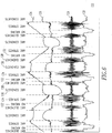
- Figure 6 shows the properties of broadband noise generated by series arcs in AC systems including the alternating current line current (e.g., 60 Hz) of an arc in series with a 5 ARMS resistive load (not shown) (e.g., an arc in series with such resistive load and generated using the carbonized path method of UL1699).
- the plot 122 of Figure 6 includes the arc voltage 124 across the series arc (not shown), the arc current 126, broadband noise 128 output by the tuned current sensor 58 of Figure 4 , and the minimum detector output 130 (e.g., 70 of Figure 4 ).
- the minimum detector output 70 as sampled by the processor 72 of Figure 4 is also shown at 130 in Figure 6 .
- This output 70,130 is proportional to the minimum of the logarithm of the envelope of the sensed broadband noise 64.
- the minimum detector output 70 "rises” when there is continuous broadband noise, indicating arcing, and does not "rise” when there is no continuous broadband noise and series arcing.
- the modulation of the broadband noise emitted by series arcs is reflected in a periodic rise and fall in the response of the minimum detector 66.
- the unusual profile of the broadband noise associated with series arcing is also believed to be determined primarily by properties of the arc (e.g.; strike; conduction; quenching) and is ideally independent of the type of load.
- plots each represent a fault event composed of many half-cycles.
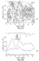
- Figures 7A is a plot 156 of 32 sample periods of an alternating current half-cycle versus counts of the minimum detector output 70 for a series arc event, which is normalized by the maximum and minimum values of counts that occurred during each half-cycle.
- Figure 7B is a plot 158 of 32 sample periods of an alternating current half-cycle versus counts of the minimum detector output 70 for a series arc event including maximum, average, minimum and standard deviation values, which is normalized by the maximum and minimum values of counts that occurred during each half-cycle.
- Figures 7A-7B show statistical analysis of the response of the minimum detector 66 of Figure 4 to a series arc.
- the processor 72 of Figure 4 samples 32 times per half-cycle the minimum detector output 70 synchronously with the AC power source. For example and without limitation, sample #1 occurs at around 0 electrical degrees of the line-to-neutral voltage, and sample #2 occurs at about 5.625 electrical degrees.
- the horizontal axis corresponds to the sample periods #1 through #32 of the processor 72 and the vertical axis corresponds to the minimum detector output 70 as measured by the processor 72 in units of normalized ADC counts ( Figures 7A and 7B ).
- Some statistical measures (e.g.; maximum; average; minimum; standard deviation) of the minimum detector output 70 in units of normalized counts of the ADC 90 versus the sampling period are shown in the plot 158 of Figure 7B .
- the standard deviation of the series arc profile is quite low compared to the average, which indicates that the minimum detector output 70 is fairly uniform from half-cycle to half-cycle during this series arc.
- the standard deviation is greatest at around samples #2 and #31, which implies that the greatest variability in the minimum detector output 70 coincides with the transition from "no arcing" 132 to "arc strikes” 134 and from "arc quenches" 138 to "no arcing” 132.
- Figure 8A is a plot 170 of 32 sample periods of an alternating current half-cycle versus counts of the minimum detector output 70 for the starting transient, which is normalized by the maximum and minimum values of counts that occurred during each half-cycle.
- Figure 8B is a plot 172 of 32 sample periods of an alternating current half-cycle versus counts of the minimum detector output 70 for the starting transient including maximum, average, minimum and standard deviation values, which is normalized by the maximum and minimum values of counts that occurred during each half-cycle.
- the peak of the minimum detector response to the fluorescent bulbs is similar to the amplitude of the response to the series arc.
- Figure 7B the same statistical analysis applied earlier ( Figure 7B ) to the series arc is applied to the fluorescent bulbs, it is clear that the broadband noise emitted by the fluorescent bulbs does not exhibit a modulation that is periodic with the source voltage, but is instead apparently random.
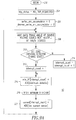
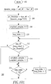
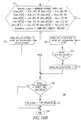
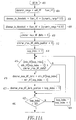
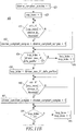
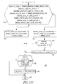
- Figures 9A , 9B , 10A , 10B , 11A , 11B and 11C form a flowchart of routines 92,300,400 for series arc fault detection.
- the routine 92 of Figures 9A and 9B begins a main loop at 202.
- hardware circuitry of Figure 4 is reset and a variable trip_status is reset to a non-trip state.
- other variables are reset including variables series_arc_accumulator ( Figures 10A-10B ) and dimmer_series_arc_accumulator ( Figures 11A-11C ).
- an array min_HF is updated with the current digital value from the ADC 90 for the minimum detector output 70.
- the minimum detector 66 is reset by pulsing processor output 94.
- an array, current is updated with the current digital value from the ADC 86 for the signal 84 from the line current sensor 80.
- the variable interrupt_count is equal to 32. If not, then execution resumes at 208. Otherwise, at 224, a variable current_integral (employed at 322 of Figure 10B and 450 of Figure 11C ) is calculated as the integral of the absolute value of the array current[1..32].
- a variable ceil_HF is set to the maximum of the array min_HF[1..32], and a variable floor_HF is set to the minimum of the array min_HF[1..32], respectively.
- the general series arc fault detection routine 300 Figures 10A-10B
- the series arc fault detection routine 400 for dimmers Figures 11A-11C
- execution resumes at 208.
- the routine 92 calculates the integral of the absolute value of the data stored in the line current array.
- the routine 92 determines the maximum and minimum values of the array of sampled minimum detection outputs, which are referred to as the "ceiling" (ceil_HF) and "floor” (floor_HF) of the minimum detector output 70.
- the general series arc fault detection routine 300 begins at 302.
- a variable dynamic_range is set to be the difference of the variables ceil_HF less floor_HF. This provides a measure of the dynamic range of the minimum detector output 70.
- the variable arc_threshold is set equal to the sum of floor HF plus one-half of dynamic_range, although any suitable threshold can be employed.
- the series arc_threshold is calculated by determining a value which is the average of the minimum detector ceiling and floor.
- the series arc threshold can be chosen below the observed average value of the minimum detector 66 during arc conduction, with enough margin above the noise floor to exclude spurious noise.
- variables compliant_samples and loop_index are initialized to zero and one, respectively.
- variable series_arc_accumulator should be increased or decreased, as will be discussed. The test is met if three conditions are true: (1) the variable dynamic_range is greater than a predetermined value (e.g., without limitation 30; any suitable value); (2) the variable floor_HF occurs at one of the samples #1 through #4 or samples #29 through #32 of the array min_HF; and (3) the count of compliant_samples is greater than a predetermined value (e.g., without limitation 24; any suitable value).
- a predetermined value e.g., without limitation 30; any suitable value
- the variable floor_HF occurs at one of the samples #1 through #4 or samples #29 through #32 of the array min_HF
- the count of compliant_samples is greater than a predetermined value (e.g., without limitation 24; any suitable value).
- variable series_arc_accumulator is increased by the variable current_integral of step 224 of Figure 9B at 322 of Figure 10B . Otherwise, the variable series_arc_accumulator is decreased by a predetermined value (e.g., without limitation 50; any suitable value) at 324. After 324, at 326, it is determined if the variable series_arc_accumulator is less than zero. If so, then the variable series_arc_accumulator is set to zero at 328. Otherwise, or after 322 or 328, at 330, it is determined if the variable series_arc_accumulator is greater than a predetermined value (e.g., without limitation 2000; any suitable value) at 330. If so, then the variable trip_status is set to request a trip at 332 (e.g., by setting the digital output 76 of Figure 4 ). Otherwise, or after 332, the routine 300 ends at 334.
- a predetermined value e.g., without limitation 2000; any suitable value
- the loop at even steps 312-318 scans samples #1 through #32 of the minimum detector array min_HF and counts those samples that are greater than the series arc threshold.
- the three-part test at 320 determines whether the minimum detector data indicates a series arc during this particular half-cycle. First, the dynamic range of the minimum detector output 70 exceeds some predetermined minimum value. If a series arc is present, then the broadband noise 128 of the load current will vary widely, as can be seen in Figure 6 . In particular, the broadband noise during the "strike” and “quench” intervals 134,138 should be much greater than the broadband noise "floor", which occurs during the "no arcing" interval 132.
- the floor value of the minimum detector 66 occurs during samples #1 through #4 or samples #29 through #32. If a series arc is present, a minimum broadband noise (as indicated by the floor of the minimum detector 66) should correspond with the "no arcing" interval 132, which roughly coincides with the zero crossings of the line-to-neutral voltage.
- phase angle of a series arc i.e., the position of arc quenches 138, no arcing 132, and arc strikes 134 of Figure 6
- Plots for inductive/capacitive loads show that the log HF minimum profile for an arc in series with inductive/capacitive loads is basically the same as the log HF minimum profile for an arc in series with a resistive load, just phase-shifted accordingly.
- the disclosed general series arc fault detection routine 300 of Figures 10A-10B advantageously detects arcs in series with loads having inductive and capacitive components by allowing the position of the HF minimum to occur in about any of the samples #1 through #4 or about any of the samples #29 through #32.
- the HF minimum exhibits generally a unity power factor for which the HF minimum occurs at about samples #1 through #3, or at about samples #31 or #32.
- the HF minimum occurs at about samples #1 through #5.
- For an arc in series with a group of computer power supplies there is generally a leading power factor that is caused by the capacitive nature of those power supplies. There, the HF minimum occurs at about samples #28 through #32.
- the series arc fault detection routine 400 for dimmers is shown. Basically, for an arc in series with dimmers with incandescent lighting loads (not shown), the log HF minimum signal is high whenever the dimmer conducts alternating current line current. This routine 400 seeks to detect this characteristic, which the general routine 300 of Figures 10A-10B cannot.
- the routine 400 begins at 402.
- a variable dynamic_range is set to be the difference of the variables ceil_HF less floor_HF. This provides a measure of the dynamic range of the minimum detector output 70.
- the variable dimmer_hi_threshold is set equal to the sum of floor_HF plus one-half of dynamic_range
- the variable dimmer_lo_threshold is set equal to the sum of floor_HF plus one-quarter of dynamic_range, respectively, although any suitable thresholds can be employed.
- the variables dimmer_max_HF_delta and dimmer_max_HF_delta_position are respectively set to zero.
- the variable loop_index is set to 2 at 414.
- variable dimmer_max_HF_delta the variable dimmer_max_HF_delta is set equal to that difference, at 418, and the variable dimmer_max_HF_delta_position is set equal to the current value of loop_index - 1, at 420. Otherwise, or after 420, it is determined if loop_index is equal to 32, at 422. If not, then loop_index is incremented, at 424, after which step 416 is repeated.
- variable dimmer_compliant_samples is set equal to zero, and the variable loop_index is set equal to one, respectively.
- step 440 it is determined if the value of the array min_HF as indexed by loop_index is greater than the variable dimmer_hi_threshold. If so, then the variable dimmer_compliant_samples is incremented at 442. Otherwise, or after 442, it is determined if loop_index is equal to 32, at 444. If not, then loop_index is incremented, at 446, after which step 440 is repeated. Otherwise, at 448, a test is performed to determine if the variable dimmer_series_arc_accumulator should be increased or decreased.
- variable dynamic_range is greater than a predetermined value (e.g., without limitation 40; any suitable value); (2) the count of dimmer_compliant_samples is greater than a predetermined value (e.g., without limitation 27; any suitable value); (3) the variable dimmer_max_HF_delta is greater than a predetermined value (e.g., without limitation 25; any suitable value); (4) the variable dimmer_max_HF_delta_position is greater than a predetermined value (e.g., without limitation 2; any suitable value); and (5) the variable dimmer_max_HF_delta_position is less than a predetermined value (e.g., without limitation 25; any suitable value).
- a predetermined value e.g., without limitation 40; any suitable value
- the count of dimmer_compliant_samples is greater than a predetermined value (e.g., without limitation 27; any suitable value)
- the variable dimmer_max_HF_delta is greater than a predetermined
- variable dimmer_series_arc_accumulator is increased by the variable current_integral (step 224 of Figure 9B ) at 450. Otherwise, the variable dimmer_series_arc_accumulator is decreased by a predetermined value (e.g., without limitation 50; any suitable value) at 452. After 452, at 454, it is determined if the variable dimmer_series_arc_accumulator is less than zero. If so, then the variable dimmer_series_arc_accumulator is set to zero at 456.
- a predetermined value e.g., without limitation 50; any suitable value
- variable dimmer_series_arc_accumulator is greater than a predetermined value (e.g., without limitation 3000; any suitable value) at 458. If so, then the variable trip_status is set to request a trip at 460 (e.g., by setting the digital output 76 of Figure 4 ). Otherwise, or after 460, the routine 400 ends at 462.
- a predetermined value e.g., without limitation 3000; any suitable value
- the width of the series arc no arcing interval (not shown, but see “no arcing” 132 of Figure 6 ) and the position of the arc re-strike (not shown, but see “arc strikes” 134 of Figure 6 ) is a function of the dimmer phase angle. Specifically, when the dimmer is set to conduct starting at a given phase angle, no series arcing occurs in the part of the half-cycle prior to that phase angle. Also, the onset of series arc conduction, which occurs at the dimmer phase angle setting, usually occurs with the largest positive step in the log HF minimum profile.
- the range of dimmer phase angle settings typically does not encompass the beginning and the end of each half-cycle.
- Each of these unique characteristics is employed in the test 448 of Figure 11C to specifically trip in response to arcs in series with incandescent lighting loads controlled by dimmers.
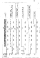
- FIG. 12 Operation of the example series arc fault detection routines 92,300 ( Figures 9A , 9B , 10A and 10B ) in response to a conventional 5 ARMS series arc is shown in Figure 12 .
- the plot 502 of Figure 12 shows the minimum detector output 146, as sampled by the processor 72, the dynamic range 504 of the minimum detector output 70 for each half-cycle (as calculated by the processor 72), a threshold 506 for the minimum dynamic range needed to indicate a potential series arc fault, and a count 508 of compliant samples (e.g., without limitation, between sample #1 and sample #32), which exceed the "arcing threshold", which (in this example) is the average of the minimum detector output ceiling and floor.
- compliant samples e.g., without limitation, between sample #1 and sample #32
- the plot 502 also shows a trace 512, which shows whether the floor of the minimum detector value falls within the expected position for that particular half-cycle: In the trace 512, a "high" signal indicates the floor of the minimum detector 66 falls within the range of positions that indicate a potential series arc fault.
- the plot 502 further shows the series arc accumulator 514. If all the conditions are true (i.e., there is sufficient dynamic range; sufficient evidence of continuous detection over the expected range of samples; and the minimum value for the broadband noise profile falls within the expected range of positions), then the integrated value of the line current is added to this accumulator 514.
- the plot 502 also shows a "trip" threshold value 516, which, if exceeded by the value of the series arc accumulator 514, will cause the processor output 76 to issue a "trip request" 518 to the trip mechanism 78 to open the separable contacts 52 of Figure 4 (see, for example, step 332 of Figure 10B and step 460 of Figure 11C ).
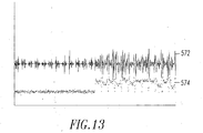
- the minimum detector output 574 does not respond to noise generated by the handheld sander (because this noise is composed of momentary, discrete bursts), but does respond to the net noise generated by the handheld sander and the series arc (because the series arc causes the net noise to be continuous throughout a substantial portion of each half-cycle).
- the periodically reset analog minimum detector 66 of Figure 4 in combination with the demodulating logarithmic amplifier 60 results in the arc fault detector 56 being highly effective at rejecting high-frequency, broadband power line noise associated with commutation arcing and power electronics switching.
- the minimum detector 66 only passes continuous bursts of high-frequency, broadband power line noise which persist for more than a predetermined time interval (e.g., as defined by the reset period of the minimum detector 66), which may then be analyzed for properties that are indicative of series arcing (as described herein).
- a predetermined time interval e.g., as defined by the reset period of the minimum detector 66
- routines 92,300,400 are based on the difference between broadband noise during arcing and the ambient noise, it is believed to be relatively insensitive to variations in the "noise floor" from distribution feeder to distribution feeder.
- the minimum detector output 70 tracks the minimum of the demodulating logarithmic amplifier output 65, so there is no need to sample rapidly to try to catch the "no arc conduction" portion of minimum broadband noise produced by the series arc. Thus, fewer samples per half-cycle can be used.
- the disclosed arc fault circuit interrupter 50 includes a suitable circuit interrupter mechanism, such as the separable contacts 52 that are opened and closed by the operating mechanism 54, although the disclosed concept is applicable to a wide range of circuit interruption mechanisms (e.g., without limitation, solid state or FET switches; contactor contacts) and/or solid state based control/protection devices (e.g., without limitation, drives; soft-starters).
- suitable circuit interrupter mechanism such as the separable contacts 52 that are opened and closed by the operating mechanism 54
- solid state based control/protection devices e.g., without limitation, drives; soft-starters.
Landscapes
- Testing Relating To Insulation (AREA)
- Emergency Protection Circuit Devices (AREA)
- Driving Mechanisms And Operating Circuits Of Arc-Extinguishing High-Tension Switches (AREA)
- Breakers (AREA)
Claims (13)
- Fehlerlichtbogenschaltungsunterbrecher (50), der Folgendes aufweist:trennbare Kontakte (52);einen Betätigungsmechanismus (54), der zum Öffnen und Schließen der trennbaren Kontakte (52) ausgebildet ist;einen Fehlerlichtbogendetektor (56), der ausgebildet ist, um einen Fehlerlichtbogenzustand zu detektieren, der im Betrieb mit den trennbaren Kontakten (52) assoziiert ist, wobei der Fehlerlichtbogendetektor Folgendes aufweist:einen eingestellten Stromsensor (58), der ausgebildet ist, um Breitbandrauschen (64) eines Stroms abzufühlen, der durch die trennbaren Kontakte (52) fließt;eine Kompressionsschaltung (60), welche eine Eingangsgröße (62) des abgefühlten Breitbandrauschens (64) von dem eingestellten Stromsensor (58) und eine Ausgangsgröße (65) aufweist, wobei die Kompressionsschaltung (60) so ausgebildet ist, dass sie den Dynamikbereich des abgefühlten Breitbandrauschens (64) komprimiert bzw. verdichtet,einen Minimumdetektor (66), der eine Eingangsgröße (68) der Ausgangsgröße (65) der Kompressionsschaltung (60) und eine Ausgangsgröße (70) des Minimumwertes der Eingangsgröße (68) des Minimumdetektors (66) aufweist, undeinen Prozessor (72), der eine Anzahl von Eingangsgrößen (74) und eine Ausgangsgröße (76) aufweist, wobei eine der Anzahl von Eingangsgrößen (74) die Ausgangsgröße (70) des Minimumwertes des Minimumdetektors (66) ist; undeinen Auslösemechanismus (78), der mit der Ausgangsgröße bzw. dem Ausgang (76) des Prozessors (72) und dem Betätigungsmechanismus (54) zusammenarbeitet, um die trennbaren Kontakte (52) ansprechend auf den detektierten Fehlerlichtbogenzustand durch Auslösen zu öffnen,wobei der Prozessor (72) ausgebildet ist, um einen Minimumwert aus der Ausgangsgröße (70) des Minimumdetektors (66) für jeden von einer Vielzahl von Leitungshalbzyklen zu bestimmen, einen Maximumwert aus der Ausgangsgröße (70) des Minimumdetektors (66) für jeden der Leitungshalbzyklen, und einen Dynamikbereichswert aus der Differenz zwischen dem Maximumwert und dem bestimmten Minimumwert zu bestimmen, und wobei der Prozessor (72) weiter ausgebildet ist zumAusführen einer Routine des Bestimmens einer Zählung einer Anzahl der Ausgangsgrößen (70) des Minimumdetektors (66), welche einen ersten vorbestimmten Wert überschreiten, für jeden der Leitungshalbzyklen, und einen Zustand, der dadurch definiert wird, dass (a) der Dynamikbereichswert größer ist als sein zweiter vorbestimmter Wert, (b) der Minimumwert bei entweder einer Vielzahl der Ausgangsgrößen des Minimumdetektors beim Beginn eines entsprechenden einen der Leitungshalbzyklen oder bei einer Vielzahl der Ausgangsgrößen (70) des Minimumdetektors (66) am Ende des entsprechenden einen der Leitungshalbzyklen auftritt, und dass (c) die Zählung der Anzahl der Ausgangsgrößen (70) des Minimumdetektors (66), welche den ersten vorbestimmten Wert überschreiten, größer ist als ein dritter vorbestimmter Wert, um einen Akkumulator bzw. Zähler ansprechend darauf zu erhöhen, dass die Bedingung erfüllt wird, oder den Akkumulator ansprechend darauf zu verringern, dass die Bedingung nicht erfüllt wird, und um den Fehlerlichtbogenzustand zu detektieren, wenn der Akkumulator einen vierten vorbestimmten Wert überschreitet oder Ausführen einer alternativen Routine des Bestimmens einer maximalen Differenz zwischen aufeinander folgenden Werten von der Ausgangsgröße (70) des Minimumdetektors (66) für jeden der Leitungshalbzyklen, einer Zählung einer Anzahl der Ausgangsgrößen des Minimumdetektors, die geringer sind als ein erster vorbestimmter Wert, für jeden der Leitungshalbzyklen plus einer Anzahl der Ausgangsgrößen (70) des Minimumdetektors (66), die größer sind als ein zweiter vorbestimmter Wert, für jeden der Leitungshalbzyklen, und eines Zustands, der dadurch definiert wird, dass (a) der Dynamikbereichswert größer ist als ein dritter vorbestimmter Wert, (b) die letzte Zählung größer ist als ein vierter vorbestimmter Wert, (c) die maximale Differenz größer ist als ein fünfter vorbestimmter Wert, (d) die maximale Differenz nach einer ersten Sample bzw. Abtastung am Beginn eines entsprechenden einen der Leitungshalbzyklen auftritt, und (e) die maximale Differenz vor einer Vielzahl von Samples bzw. Abtastungen am Ende des entsprechenden einen der Leitungshalbzyklen auftritt, um einen Akkumulator bzw. Zähler ansprechend darauf zu erhöhen, dass die Bedingung erfüllt wird, oder den Akkumulator ansprechend darauf zu verringern, dass die Bedingung nicht erfüllt wird, und um den Fehlerlichtbogenzustand zu detektieren, wenn der Akkumulator einen sechsten vorbestimmten Wert überschreitet.
- Fehlerlichtbogenschaltungsunterbrecher (50) nach Anspruch 1, wobei der eingestellte Stromsensor (58) ausgebildet ist, um das abgefühlten Breitbandrauschen (64) auszugeben und/oder
wobei vorzugsweise der eingestellte Stromsensor (58) ein Stromwandler ist, der ausgebildet ist, um bei ungefähr 15 MHz eine Resonanz zu zeigen, und/oder
wobei vorzugsweise die Kompressionsschaltung (60) ein demodulierender logarithmischer Verstärker ist, der ausgebildet ist, um das abgefühlte Breitbandrauschen (64) gleichzurichten und eine logarithmische Umwandlung der Amplitude des gleichgerichteten abgefühlten Breitbandrauschens auszuführen, und/oder
wobei vorzugsweise der Prozessor (72) so strukturiert ist, dass er periodisch die Ausgangsgröße (70) des Minimumdetektors (66) eingibt bzw. aufnimmt. - Fehlerlichtbogenschaltungsunterbrecher (50) nach Anspruch 1 oder 2, wobei der Prozessor (72) weiter ausgebildet ist, um die Ausgangsgröße (70) des Minimumdetektors (66) synchron mit einem Wechselstromhalbzyklus einzugeben bzw. aufzunehmen, ein Profil der Ausgangsgröße des Minimumdetektors gegenüber einem Phasenwinkel des Wechselstromhalbzyklus mit einer Vielzahl von Profilen zu vergleichen, die im Betrieb mit Reihenlichtbögen assoziiert sind, und zu bestimmen, ob jeder Wechselstromhalbzyklus einem der Vielzahl von Profilen entspricht.
- Fehlerlichtbogenschaltungsunterbrecher (50) nach Anspruch 1, wobei der Minimumdetektor (66) ausgebildet ist, um diskret beabstandete Hochfrequenzimpulse des abgefühlten Breitbandrauschens (64) zurückzuweisen und/oder
wobei vorzugsweise die diskret beabstandeten Hochfrequenzimpulse des abgefühlten Breitbandrauschens (64) durch einen Universalmotor und/oder eine Leistungsversorgung erzeugt werden, und/oder
wobei vorzugsweise der Minimumdetektor (66) ausgebildet ist, um Hochfrequenzimpulse des abgefühlten Breitbandrauschens (64) aus dem Fehlerlichtbogenzustand durchzulassen, und/oder
wobei vorzugsweise der Fehlerlichtbogendetektor (56) weiter einen Leitungsstromsensor (80) aufweist, der einen Ausgang bzw. eine Ausgangsgröße (82) aufweist, der ausgebildet ist, um ein Signal proportional zu dem Leistungsstrom auszugeben; und wobei einer der Anzahl von Eingängen bzw. Eingangsgrößen (74) des Prozessors (72) der Ausgang bzw. die Ausgangsgröße (82) des Leitungsstromsensors (80) ist, und/oder
wobei vorzugsweise der Fehlerlichtbogendetektor (56) weiter einen Leitungsspannungsnulldurchgangsdetektor (88) aufweist, der ausgebildet ist, um den Prozessor (72) mit einer Leitungsspannung zu synchronisieren, und/oder
wobei vorzugsweise der Prozessor (72) einen Analog-Digital-Wandler aufweist, der ausgebildet ist, um die Ausgangsgröße des Minimumdetektors (66) einzugeben bzw. aufzunehmen und umzuwandeln. - Fehlerlichtbogenschaltungsunterbrecher (50) nach Anspruch 1, wobei die Ausgangsgröße des Minimumdetektors (66) proportional zum Minimum des Logarithmus der Hüllkurve des abgefühlten Breitbandrauschens (64) ist; wobei die Ausgangsgröße (70) des Minimumdetektors (66) ausgebildet ist, um ansprechend auf kontinuierliches Breitbandrauschen (64) von dem Fehlerlichtbogenzustand zuzunehmen; und wobei die Ausgangsgröße (70) des Minimumdetektors (66) ausgebildet ist, um ansprechend auf nicht kontinuierliches Breitbandrauschen nicht zuzunehmen.
- Fehlerlichtbogenschaltungsunterbrecher (50) nach Anspruch 1, wobei der Prozessor (72) ausgebildet ist, um zu bestimmen, ob eine vorbestimmte Anzahl von Wechselstromhalbzyklen eine Reihenlichtbogenbildung anzeigt, die in einem vorbestimmten Zeitintervall auftritt, und um darauf ansprechend die Ausgangsgröße (67) des Prozessors (72) so einzustellen, dass die trennbaren Kontakte (52) darauf ansprechend zum Öffnen ausgelöst werden.
- Fehlerlichtbogenschaltungsunterbrecher (50) nach Anspruch 1, wobei der Fehlerlichtbogendetektor (56) weiter einen Nulldurchgangsdetektor (88) aufweist, der ausgebildet ist, um den Prozessor mit einer Vielzahl von Leitungshalbzyklen zu synchronisieren; und wobei der Prozessor einen Analog-Digital-Wandler aufweist, der ausgebildet ist, um die Ausgangsgröße des Minimumdetektors aufzunehmen und umzuwandeln, und eine Routine, die ausgebildet ist, um die Ausgangsgröße des Minimumdetektors eine Vielzahl von Malen für jeden der Leitungshalbzyklen aufzunehmen und zurückzusetzen.
- Fehlerlichtbogenschaltungsunterbrecher (50) nach Anspruch 1, wobei, wenn der Prozessor konfiguriert ist, um die Routine auszuführen, der Prozessor (72) weiter ausgebildet ist, um 32 Samples bzw. Abtastungen der Ausgangsgrößen (70) des Minimumdetektors (66) für jeden der Leitungshalbzyklen aufzunehmen; wobei die Vielzahl der Ausgangsgrößen (70) des Minimumdetektors (66) zum Beginn des entsprechenden einen der Leitungshalbzyklen ungefähr die ersten fünf der 32 Abtastungen sind; und wobei die Vielzahl der Ausgangsgrößen (70) des Minimumdetektors (66) am Ende des entsprechenden einen der Leitungshalbzyklen ungefähr die letzten fünf der 32 Abtastungen sind.
- Fehlerlichtbogenschaltungsunterbrecher (50) nach Anspruch 1, wobei, wenn der Prozessor konfiguriert ist, um die Routine auszuführen, der Prozessor (72) weiter ausgebildet ist, um 32 Samples bzw. Abtastungen der Ausgangsgrößen (70) des Minimumdetektors (66) für jeden der Leitungshalbzyklen aufzunehmen; wobei die Vielzahl der Ausgangsgrößen (70) des Minimumdetektors (66) zum Beginn des entsprechenden einen der Leitungshalbzyklen ungefähr die ersten drei der 32 Abtastungen sind; und wobei die Vielzahl der Ausgangsgrößen (70) des Minimumdetektors (66) am Ende des entsprechenden einen der Leitungshalbzyklen ungefähr die letzten zwei der 32 Abtastungen sind.
- Fehlerlichtbogenschaltungsunterbrecher (50) nach Anspruch 1, wobei, wenn der Prozessor konfiguriert ist, die alternative Routine auszuführen, der Prozessor (72) weiter ausgebildet ist, um 32 Samples bzw. Abtastungen der Ausgangsgrößen (70) des Minimumdetektors (66) für jeden der Leitungshalbzyklen aufzunehmen; und wobei der Maximumwert vor ungefähr der 25. der 32 Abtastungen am Ende des entsprechenden einen der Leitungshalbzyklen auftritt, und/oder
wobei der Prozessor (72) weiter ausgebildet ist, um die Ausgangsgröße (70) des Minimumdetektors (66) eine Vielzahl von Malen für jeden der Vielzahl von Leitungshalbzyklen einzugeben bzw. aufzunehmen und zurückzusetzen, einen maximalen Veränderungswert zwischen benachbarten Paaren der Ausgangsgröße (70) des Minimumdetektors (66) für die Vielzahl von Malen für jeden der Vielzahl von Leitungshalbzyklen zu bestimmen, einen Positionswert entsprechend dem maximalen Veränderungswert für eines der Vielzahl von Malen, und eine Bedingung zu bestimmen, die dadurch definiert wird, dass: (a) der Dynamikbereichswert größer ist als ein sechster vorbestimmter Wert, (b) der maximale Veränderungswert größer ist als ein siebter vorbestimmter Wert, (c) der Positionswert größer als ein achter vorbestimmter Wert und geringer ist als ein neunter vorbestimmter Wert und (d) die Zählung größer als ein zehnter vorbestimmter Wert ist. - Fehlerlichtbogenschaltungsunterbrecher (50) nach Anspruch 1, wobei, wenn der Prozessor konfiguriert ist, die alternative Routine auszuführen, der Prozessor weiter ausgebildet ist, eine Zählung einer Anzahl der Ausgangsgrößen (70) des Minimumdetektors (66) zu bestimmen, die entweder den ersten vorbestimmten Wert überschreiten, und zwar für jeden der Leitungshalbzyklen, oder die kleiner sind als ein fünfter vorbestimmter Wert, und zwar für jeden der Leitungshalbzyklen, einen maximalen Veränderungswert zwischen benachbarten Paaren der Ausgangsgröße (70) des Minimumdetektors (66) für die Vielzahl von Malen zu bestimmen, und zwar für jeden der Leitungshalbzyklen, einen Positionswert entsprechend dem maximalen Veränderungswert für eines der Vielzahl von Malen zu bestimmen, und eine Bedingung zu bestimmen, die dadurch definiert wird, dass (a) der Dynamikbereichswert größer ist als ein sechster vorbestimmter Wert, (b) der maximale Veränderungswert größer ist als ein siebter vorbestimmter Wert, (c) der Positionswert größer als ein achter vorbestimmter Wert und geringer ist als ein neunter vorbestimmter Wert und (d) die Zählung größer als ein zehnter vorbestimmter Wert ist.
- Verfahren zum Detektieren eines Fehlerlichtbogenzustandes einer Wechselstromschaltung mit einer Vielzahl von Halbzyklen, wobei das Verfahren Folgendes aufweist:Abfühlen eines Breitbandrauschens eines Stroms, der in der Stromschaltung fließt;Komprimieren des Dynamikbereiches des abgefühlten Breitbandrauschens;Detektieren eines Minimums des komprimierten und abgefühlten Breitbandrauschens für eine Vielzahl von Samples bzw. Abtastungen für jeden der Halbzyklen;Bestimmen eines Minimumwertes aus dem Minimum des komprimierten und abgefühlten Breitbandrauschens für die Abtastungen für jeden der Halbzyklen;Bestimmen eines Maximumwertes aus dem Minimum des komprimierten und abgefühlten Breitbandrauschens für die Abtastungen für jeden der Halbzyklen;Bestimmen eines Dynamikbereichswertes aus der Differenz zwischen dem Maximumwert und dem Minimumwert;Bestimmen einer Zählung einer Anzahl der Abtastungen, die einen ersten vorbestimmten Wert überschreiten, für jeden der Halbzyklen;Bestimmen einer Bedingung, die dadurch definiert wird, dass (a) der Dynamikbereichswert größer ist als ein zweiter vorbestimmter Wert, dass (b) der Minimumwert bei einer von entweder einer Vielzahl von Abtastungen am Beginn eines entsprechenden einen der Leitungshalbzyklen oder einer Vielzahl von Abtastungen am Ende des entsprechenden einen der Leitungshalbzyklen auftritt, und dass (c) die Zählung der Anzahl der Abtastungen, die den ersten vorbestimmten Wert überschreiten, größer ist als ein dritter vorbestimmter Wert;Erhöhen eines Akkumulators bzw. Zählers ansprechend darauf, dass die Bedingung erfüllt wird, oder Verringern des Akkumulators ansprechend darauf, dass die Bedingung nicht erfüllt wird; undDetektieren des Fehlerlichtbogenzustandes, wenn der Akkumulator einen vierten vorbestimmten Wert überschreitet.
- Verfahren zum Detektieren eines Fehlerlichtbogenzustandes einer Wechselstromschaltung mit einer Vielzahl von Halbzyklen, wobei das Verfahren Folgendes aufweist:Abfühlen eines Breitbandrauschens eines Stroms, der in der Stromschaltung fließt;Komprimieren des Dynamikbereiches des abgefühlten Breitbandrauschens;Detektieren eines Minimums des komprimierten und abgefühlten Breitbandrauschens für eine Vielzahl von Samples bzw. Abtastungen für jeden der Halbzyklen;Bestimmen eines Minimumwertes aus dem Minimum des komprimierten und abgefühlten Breitbandrauschens für die Abtastungen für jeden der Halbzyklen;Bestimmen eines Maximumwertes aus dem Minimum des komprimierten und abgefühlten Breitbandrauschens für die Abtastungen für jeden der Halbzyklen;Bestimmen eines Dynamikbereichswertes aus der Differenz zwischen dem Maximumwert und dem Minimumwert;Bestimmen einer maximalen Differenz zwischen aufeinander folgenden Werten aus dem Minimum des komprimierten und abgefühlten Breitbandrauschens für jeden der Leitungshalbzyklen,Bestimmen einer Zählung einer Anzahl des Minimums bzw. der Minima des komprimierten und abgefühlten Breitbandrauschens, die geringer sind als ein erster vorbestimmter Wert, und zwar für jeden der Leitungshalbzyklen, plus einer Anzahl des Minimums bzw. der Minima des komprimierten und abgefühlten Breitbandrauschens, die größer sind als ein zweiter vorbestimmter Wert, und zwar für jeden der Leitungshalbzyklen;Bestimmen eines Zustandes, der dadurch definiert ist, dass (a) der Dynamikbereichswert größer ist als ein dritter vorbestimmter Wert, (b) die letzte der Zählungen größer ist als ein vierter vorbestimmter Wert, (c) die maximale Differenz größer ist als ein fünfter vorbestimmter Wert, (d) die maximale Differenz nach einer ersten Sample bzw. Abtastung am Beginn eines entsprechenden einen der Leitungshalbzyklen auftritt, und (e) die maximale Differenz vor einer Vielzahl von Abtastungen am Ende des entsprechenden einen der Leitungshalbzyklen auftritt;Erhöhen eines Akkumulators bzw. Zählers ansprechend darauf, dass die Bedingung erfüllt wird, oder Verringern des Akkumulators ansprechend darauf, dass die Bedingung nicht erfüllt wird; undDetektieren des Fehlerlichtbogenzustandes, wenn der Akkumulator einen sechsten vorbestimmten Wert überschreitet.
Applications Claiming Priority (2)
| Application Number | Priority Date | Filing Date | Title |
|---|---|---|---|
| US12/339,516 US8089737B2 (en) | 2008-12-19 | 2008-12-19 | Arc fault circuit interrupter and method providing improved nuisance trip rejection |
| PCT/IB2009/007811 WO2010070436A1 (en) | 2008-12-19 | 2009-12-18 | Arc fault circuit interrupter and method providing improved nuisance trip rejection |
Publications (2)
| Publication Number | Publication Date |
|---|---|
| EP2368302A1 EP2368302A1 (de) | 2011-09-28 |
| EP2368302B1 true EP2368302B1 (de) | 2020-04-15 |
Family
ID=42173251
Family Applications (1)
| Application Number | Title | Priority Date | Filing Date |
|---|---|---|---|
| EP09805821.7A Active EP2368302B1 (de) | 2008-12-19 | 2009-12-18 | Bogenfehler-unterbrecherschalter und verfahren zur gewährleistung von verbesserter zurückweisung von falschen auslösungen |
Country Status (8)
| Country | Link |
|---|---|
| US (1) | US8089737B2 (de) |
| EP (1) | EP2368302B1 (de) |
| BR (1) | BRPI0918111A2 (de) |
| CA (1) | CA2746578C (de) |
| CR (1) | CR20110390U (de) |
| ES (1) | ES2790899T3 (de) |
| MX (1) | MX2011006690A (de) |
| WO (1) | WO2010070436A1 (de) |
Families Citing this family (23)
| Publication number | Priority date | Publication date | Assignee | Title |
|---|---|---|---|---|
| US8339275B2 (en) * | 2009-08-07 | 2012-12-25 | Fluke Corporation | AC voltage phase discriminator for circuit breaker locators |
| US8421473B2 (en) * | 2010-05-10 | 2013-04-16 | Eaton Corporation | Apparatus and method to detect a series arc fault of an electrical circuit |
| US9043039B2 (en) | 2011-02-24 | 2015-05-26 | Tigo Energy, Inc. | System and method for arc detection and intervention in solar energy systems |
| US9431816B2 (en) * | 2012-09-28 | 2016-08-30 | Eaton Corporation | Direct current arc fault detector and circuit interrupter, and method of detecting an arc in a direct current power circuit |
| US8749929B1 (en) * | 2012-12-17 | 2014-06-10 | Eaton Corporation | Circuit interrupter providing ground fault protection and system including the same |
| WO2015153503A2 (en) | 2014-03-31 | 2015-10-08 | Hubbell Incorporated | Systems and methods for detecting and identifying arcing based on numerical analysis |
| US10461519B2 (en) | 2013-03-14 | 2019-10-29 | Hubbell Incorporated | Systems and methods for detecting and identifying arcing |
| WO2014186926A1 (zh) * | 2013-05-23 | 2014-11-27 | Ge Jianyou | 一种漏电警示与保护电路 |
| CN105308813B (zh) * | 2013-06-21 | 2019-02-15 | 施耐德电气美国股份有限公司 | 使用在插座处的开关元件检测电弧故障的方法 |
| WO2014209311A1 (en) | 2013-06-27 | 2014-12-31 | Schneider Electric USA, Inc. | Adaptive arc fault detection trip decision buffer |
| US9036318B2 (en) | 2013-07-09 | 2015-05-19 | Eaton Corporation | Method of tripping a circuit interrupter in a back fed configuration |
| US10288675B2 (en) * | 2013-12-17 | 2019-05-14 | Eaton Intelligent Power Limited | Remote diagnostic system and method for circuit protection devices such as miniature circuit breakers |
| US9625499B2 (en) | 2014-05-01 | 2017-04-18 | Eaton Corporation | Receptacle indicating relative level of current or energy |
| KR101922553B1 (ko) * | 2015-11-17 | 2018-11-27 | 주식회사 엘지화학 | 바이메탈을 이용한 릴레이 독립 제어 시스템 및 방법 |
| US10345357B2 (en) * | 2016-02-29 | 2019-07-09 | The Boeing Company | Fault detection in variable differential transformer sensors based on zero-crossings of signals |
| US10060964B2 (en) | 2016-03-21 | 2018-08-28 | Eaton Intelligent Power Limited | Arc fault circuit interrupter detector systems including super regenerative high frequency receiver |
| DE102016209443B4 (de) * | 2016-05-31 | 2021-06-10 | Siemens Aktiengesellschaft | Störlichtbogenerkennungseinheit |
| WO2018217883A2 (en) | 2017-05-23 | 2018-11-29 | Pass & Seymour, Inc. | Arc fault circuit interrupter |
| US10666036B2 (en) | 2017-12-21 | 2020-05-26 | Eaton Intelligent Power Limited | Arc fault detection system |
| US11300601B2 (en) * | 2018-06-15 | 2022-04-12 | Schneider Electric USA, Inc. | Arc fault detection using single current sensor and wideband analog frontend |
| GB2579859A (en) * | 2018-12-18 | 2020-07-08 | Eaton Intelligent Power Ltd | Arc fault detector |
| EP3974848B1 (de) | 2020-09-24 | 2024-07-31 | ABB Schweiz AG | Lichtbogenfehlererkennungsvorrichtung mit breitbandsensor |
| US12348024B2 (en) * | 2022-02-07 | 2025-07-01 | Hubbell Incorporated | Arc fault detection through mixed-signal machine learning and neural networks |
Family Cites Families (17)
| Publication number | Priority date | Publication date | Assignee | Title |
|---|---|---|---|---|
| US5224006A (en) | 1991-09-26 | 1993-06-29 | Westinghouse Electric Corp. | Electronic circuit breaker with protection against sputtering arc faults and ground faults |
| US5729145A (en) | 1992-07-30 | 1998-03-17 | Siemens Energy & Automation, Inc. | Method and apparatus for detecting arcing in AC power systems by monitoring high frequency noise |
| US5432455A (en) | 1992-07-30 | 1995-07-11 | Blades; Frederick K. | Method and apparatus for detecting arcing in alternating current power systems by monitoring high-frequency noise |
| US5434509A (en) | 1992-07-30 | 1995-07-18 | Blades; Frederick K. | Method and apparatus for detecting arcing in alternating-current power systems by monitoring high-frequency noise |
| US5691869A (en) | 1995-06-06 | 1997-11-25 | Eaton Corporation | Low cost apparatus for detecting arcing faults and circuit breaker incorporating same |
| US6362628B2 (en) * | 1998-12-21 | 2002-03-26 | Pass & Seymour, Inc. | Arc fault circuit detector device detecting pulse width modulation of arc noise |
| US6522509B1 (en) | 2000-07-21 | 2003-02-18 | Eaton Corporation | Arc fault detection in ac electric power systems |
| US6522228B2 (en) | 2001-04-30 | 2003-02-18 | Eaton Corporation | Circuit breaker including an arc fault trip actuator having an indicator latch and a trip latch |
| US6710688B2 (en) | 2001-04-30 | 2004-03-23 | Eaton Corporation | Circuit breaker |
| US6542056B2 (en) | 2001-04-30 | 2003-04-01 | Eaton Corporation | Circuit breaker having a movable and illuminable arc fault indicator |
| US6577138B2 (en) * | 2001-08-24 | 2003-06-10 | Eaton Corporation | Apparatus for detecting arcing and overcurrents in dc electrical systems subject to cyclic disturbances |
| US7110864B2 (en) | 2004-03-08 | 2006-09-19 | Siemens Energy & Automation, Inc. | Systems, devices, and methods for detecting arcs |
| US7307820B2 (en) | 2004-06-21 | 2007-12-11 | Siemens Energy & Automation, Inc. | Systems, methods, and device for arc fault detection |
| US7441173B2 (en) | 2006-02-16 | 2008-10-21 | Siemens Energy & Automation, Inc. | Systems, devices, and methods for arc fault detection |
| US7368918B2 (en) | 2006-07-27 | 2008-05-06 | Siemens Energy & Automation | Devices, systems, and methods for adaptive RF sensing in arc fault detection |
| US7864492B2 (en) | 2006-10-31 | 2011-01-04 | Siemens Industry, Inc. | Systems and methods for arc fault detection |
| US7746605B2 (en) * | 2007-08-07 | 2010-06-29 | Eaton Corporation | Arc fault circuit interrupter and method of detecting and interrupting a resistive series arc of a power circuit |
-
2008
- 2008-12-19 US US12/339,516 patent/US8089737B2/en active Active
-
2009
- 2009-12-18 WO PCT/IB2009/007811 patent/WO2010070436A1/en not_active Ceased
- 2009-12-18 EP EP09805821.7A patent/EP2368302B1/de active Active
- 2009-12-18 CA CA2746578A patent/CA2746578C/en active Active
- 2009-12-18 MX MX2011006690A patent/MX2011006690A/es active IP Right Grant
- 2009-12-18 ES ES09805821T patent/ES2790899T3/es active Active
- 2009-12-18 BR BRPI0918111A patent/BRPI0918111A2/pt not_active Application Discontinuation
-
2011
- 2011-07-19 CR CR20110390U patent/CR20110390U/es unknown
Non-Patent Citations (1)
| Title |
|---|
| None * |
Also Published As
| Publication number | Publication date |
|---|---|
| US20100157486A1 (en) | 2010-06-24 |
| CA2746578C (en) | 2016-07-12 |
| CA2746578A1 (en) | 2010-06-24 |
| US8089737B2 (en) | 2012-01-03 |
| EP2368302A1 (de) | 2011-09-28 |
| ES2790899T3 (es) | 2020-10-29 |
| AU2009329268A1 (en) | 2011-07-07 |
| BRPI0918111A2 (pt) | 2015-11-24 |
| MX2011006690A (es) | 2011-09-01 |
| CR20110390U (es) | 2012-07-02 |
| WO2010070436A1 (en) | 2010-06-24 |
Similar Documents
| Publication | Publication Date | Title |
|---|---|---|
| EP2368302B1 (de) | Bogenfehler-unterbrecherschalter und verfahren zur gewährleistung von verbesserter zurückweisung von falschen auslösungen | |
| US7558033B2 (en) | Arc fault circuit interrupter and method of parallel and series arc fault detection | |
| US7633727B2 (en) | Arc fault circuit interrupter and series arc fault detection method using plural high frequency bands | |
| US9638738B2 (en) | Apparatus and method to detect a series arc fault of an electrical circuit | |
| US7570465B2 (en) | Industrial arc fault circuit interrupter and method of detecting arcing conditions | |
| US7633728B2 (en) | Arc fault circuit interrupter and method of parallel arc fault detection | |
| US7268989B2 (en) | Arc fault circuit interrupter for a compressor load | |
| US7359168B2 (en) | Arc fault circuit interrupter and method for disabling series arc protection during current transients | |
| US7362553B2 (en) | Arc fault circuit interrupter and method for inhibiting series arc protection based on dimmer phase angle | |
| AU2009329268B2 (en) | Arc fault circuit interrupter and method providing improved nuisance trip rejection |
Legal Events
| Date | Code | Title | Description |
|---|---|---|---|
| PUAI | Public reference made under article 153(3) epc to a published international application that has entered the european phase |
Free format text: ORIGINAL CODE: 0009012 |
|
| 17P | Request for examination filed |
Effective date: 20110617 |
|
| AK | Designated contracting states |
Kind code of ref document: A1 Designated state(s): AT BE BG CH CY CZ DE DK EE ES FI FR GB GR HR HU IE IS IT LI LT LU LV MC MK MT NL NO PL PT RO SE SI SK SM TR |
|
| DAX | Request for extension of the european patent (deleted) | ||
| STAA | Information on the status of an ep patent application or granted ep patent |
Free format text: STATUS: EXAMINATION IS IN PROGRESS |
|
| 17Q | First examination report despatched |
Effective date: 20180704 |
|
| GRAP | Despatch of communication of intention to grant a patent |
Free format text: ORIGINAL CODE: EPIDOSNIGR1 |
|
| STAA | Information on the status of an ep patent application or granted ep patent |
Free format text: STATUS: GRANT OF PATENT IS INTENDED |
|
| INTG | Intention to grant announced |
Effective date: 20191210 |
|
| GRAS | Grant fee paid |
Free format text: ORIGINAL CODE: EPIDOSNIGR3 |
|
| GRAA | (expected) grant |
Free format text: ORIGINAL CODE: 0009210 |
|
| STAA | Information on the status of an ep patent application or granted ep patent |
Free format text: STATUS: THE PATENT HAS BEEN GRANTED |
|
| AK | Designated contracting states |
Kind code of ref document: B1 Designated state(s): AT BE BG CH CY CZ DE DK EE ES FI FR GB GR HR HU IE IS IT LI LT LU LV MC MK MT NL NO PL PT RO SE SI SK SM TR |
|
| REG | Reference to a national code |
Ref country code: GB Ref legal event code: FG4D Ref country code: CH Ref legal event code: EP |
|
| REG | Reference to a national code |
Ref country code: DE Ref legal event code: R096 Ref document number: 602009061748 Country of ref document: DE |
|
| REG | Reference to a national code |
Ref country code: IE Ref legal event code: FG4D |
|
| REG | Reference to a national code |
Ref country code: AT Ref legal event code: REF Ref document number: 1258411 Country of ref document: AT Kind code of ref document: T Effective date: 20200515 |
|
| REG | Reference to a national code |
Ref country code: NL Ref legal event code: MP Effective date: 20200415 |
|
| REG | Reference to a national code |
Ref country code: LT Ref legal event code: MG4D |
|
| REG | Reference to a national code |
Ref country code: ES Ref legal event code: FG2A Ref document number: 2790899 Country of ref document: ES Kind code of ref document: T3 Effective date: 20201029 |
|
| PG25 | Lapsed in a contracting state [announced via postgrant information from national office to epo] |
Ref country code: PT Free format text: LAPSE BECAUSE OF FAILURE TO SUBMIT A TRANSLATION OF THE DESCRIPTION OR TO PAY THE FEE WITHIN THE PRESCRIBED TIME-LIMIT Effective date: 20200817 Ref country code: IS Free format text: LAPSE BECAUSE OF FAILURE TO SUBMIT A TRANSLATION OF THE DESCRIPTION OR TO PAY THE FEE WITHIN THE PRESCRIBED TIME-LIMIT Effective date: 20200815 Ref country code: SE Free format text: LAPSE BECAUSE OF FAILURE TO SUBMIT A TRANSLATION OF THE DESCRIPTION OR TO PAY THE FEE WITHIN THE PRESCRIBED TIME-LIMIT Effective date: 20200415 Ref country code: FI Free format text: LAPSE BECAUSE OF FAILURE TO SUBMIT A TRANSLATION OF THE DESCRIPTION OR TO PAY THE FEE WITHIN THE PRESCRIBED TIME-LIMIT Effective date: 20200415 Ref country code: GR Free format text: LAPSE BECAUSE OF FAILURE TO SUBMIT A TRANSLATION OF THE DESCRIPTION OR TO PAY THE FEE WITHIN THE PRESCRIBED TIME-LIMIT Effective date: 20200716 Ref country code: NO Free format text: LAPSE BECAUSE OF FAILURE TO SUBMIT A TRANSLATION OF THE DESCRIPTION OR TO PAY THE FEE WITHIN THE PRESCRIBED TIME-LIMIT Effective date: 20200715 Ref country code: LT Free format text: LAPSE BECAUSE OF FAILURE TO SUBMIT A TRANSLATION OF THE DESCRIPTION OR TO PAY THE FEE WITHIN THE PRESCRIBED TIME-LIMIT Effective date: 20200415 Ref country code: NL Free format text: LAPSE BECAUSE OF FAILURE TO SUBMIT A TRANSLATION OF THE DESCRIPTION OR TO PAY THE FEE WITHIN THE PRESCRIBED TIME-LIMIT Effective date: 20200415 |
|
| RAP2 | Party data changed (patent owner data changed or rights of a patent transferred) |
Owner name: EATON INTELLIGENT POWER LIMITED |
|
| REG | Reference to a national code |
Ref country code: AT Ref legal event code: MK05 Ref document number: 1258411 Country of ref document: AT Kind code of ref document: T Effective date: 20200415 |
|
| PG25 | Lapsed in a contracting state [announced via postgrant information from national office to epo] |
Ref country code: BG Free format text: LAPSE BECAUSE OF FAILURE TO SUBMIT A TRANSLATION OF THE DESCRIPTION OR TO PAY THE FEE WITHIN THE PRESCRIBED TIME-LIMIT Effective date: 20200715 Ref country code: LV Free format text: LAPSE BECAUSE OF FAILURE TO SUBMIT A TRANSLATION OF THE DESCRIPTION OR TO PAY THE FEE WITHIN THE PRESCRIBED TIME-LIMIT Effective date: 20200415 Ref country code: HR Free format text: LAPSE BECAUSE OF FAILURE TO SUBMIT A TRANSLATION OF THE DESCRIPTION OR TO PAY THE FEE WITHIN THE PRESCRIBED TIME-LIMIT Effective date: 20200415 |
|
| REG | Reference to a national code |
Ref country code: DE Ref legal event code: R097 Ref document number: 602009061748 Country of ref document: DE |
|
| PG25 | Lapsed in a contracting state [announced via postgrant information from national office to epo] |
Ref country code: RO Free format text: LAPSE BECAUSE OF FAILURE TO SUBMIT A TRANSLATION OF THE DESCRIPTION OR TO PAY THE FEE WITHIN THE PRESCRIBED TIME-LIMIT Effective date: 20200415 Ref country code: DK Free format text: LAPSE BECAUSE OF FAILURE TO SUBMIT A TRANSLATION OF THE DESCRIPTION OR TO PAY THE FEE WITHIN THE PRESCRIBED TIME-LIMIT Effective date: 20200415 Ref country code: SM Free format text: LAPSE BECAUSE OF FAILURE TO SUBMIT A TRANSLATION OF THE DESCRIPTION OR TO PAY THE FEE WITHIN THE PRESCRIBED TIME-LIMIT Effective date: 20200415 Ref country code: EE Free format text: LAPSE BECAUSE OF FAILURE TO SUBMIT A TRANSLATION OF THE DESCRIPTION OR TO PAY THE FEE WITHIN THE PRESCRIBED TIME-LIMIT Effective date: 20200415 Ref country code: AT Free format text: LAPSE BECAUSE OF FAILURE TO SUBMIT A TRANSLATION OF THE DESCRIPTION OR TO PAY THE FEE WITHIN THE PRESCRIBED TIME-LIMIT Effective date: 20200415 Ref country code: CZ Free format text: LAPSE BECAUSE OF FAILURE TO SUBMIT A TRANSLATION OF THE DESCRIPTION OR TO PAY THE FEE WITHIN THE PRESCRIBED TIME-LIMIT Effective date: 20200415 |
|
| PLBE | No opposition filed within time limit |
Free format text: ORIGINAL CODE: 0009261 |
|
| STAA | Information on the status of an ep patent application or granted ep patent |
Free format text: STATUS: NO OPPOSITION FILED WITHIN TIME LIMIT |
|
| PG25 | Lapsed in a contracting state [announced via postgrant information from national office to epo] |
Ref country code: PL Free format text: LAPSE BECAUSE OF FAILURE TO SUBMIT A TRANSLATION OF THE DESCRIPTION OR TO PAY THE FEE WITHIN THE PRESCRIBED TIME-LIMIT Effective date: 20200415 Ref country code: SK Free format text: LAPSE BECAUSE OF FAILURE TO SUBMIT A TRANSLATION OF THE DESCRIPTION OR TO PAY THE FEE WITHIN THE PRESCRIBED TIME-LIMIT Effective date: 20200415 |
|
| 26N | No opposition filed |
Effective date: 20210118 |
|
| PG25 | Lapsed in a contracting state [announced via postgrant information from national office to epo] |
Ref country code: SI Free format text: LAPSE BECAUSE OF FAILURE TO SUBMIT A TRANSLATION OF THE DESCRIPTION OR TO PAY THE FEE WITHIN THE PRESCRIBED TIME-LIMIT Effective date: 20200415 |
|
| REG | Reference to a national code |
Ref country code: CH Ref legal event code: PL |
|
| PG25 | Lapsed in a contracting state [announced via postgrant information from national office to epo] |
Ref country code: MC Free format text: LAPSE BECAUSE OF FAILURE TO SUBMIT A TRANSLATION OF THE DESCRIPTION OR TO PAY THE FEE WITHIN THE PRESCRIBED TIME-LIMIT Effective date: 20200415 |
|
| REG | Reference to a national code |
Ref country code: BE Ref legal event code: MM Effective date: 20201231 |
|
| PG25 | Lapsed in a contracting state [announced via postgrant information from national office to epo] |
Ref country code: IE Free format text: LAPSE BECAUSE OF NON-PAYMENT OF DUE FEES Effective date: 20201218 Ref country code: LU Free format text: LAPSE BECAUSE OF NON-PAYMENT OF DUE FEES Effective date: 20201218 |
|
| PG25 | Lapsed in a contracting state [announced via postgrant information from national office to epo] |
Ref country code: CH Free format text: LAPSE BECAUSE OF NON-PAYMENT OF DUE FEES Effective date: 20201231 Ref country code: LI Free format text: LAPSE BECAUSE OF NON-PAYMENT OF DUE FEES Effective date: 20201231 |
|
| PG25 | Lapsed in a contracting state [announced via postgrant information from national office to epo] |
Ref country code: TR Free format text: LAPSE BECAUSE OF FAILURE TO SUBMIT A TRANSLATION OF THE DESCRIPTION OR TO PAY THE FEE WITHIN THE PRESCRIBED TIME-LIMIT Effective date: 20200415 Ref country code: MT Free format text: LAPSE BECAUSE OF FAILURE TO SUBMIT A TRANSLATION OF THE DESCRIPTION OR TO PAY THE FEE WITHIN THE PRESCRIBED TIME-LIMIT Effective date: 20200415 Ref country code: CY Free format text: LAPSE BECAUSE OF FAILURE TO SUBMIT A TRANSLATION OF THE DESCRIPTION OR TO PAY THE FEE WITHIN THE PRESCRIBED TIME-LIMIT Effective date: 20200415 |
|
| PG25 | Lapsed in a contracting state [announced via postgrant information from national office to epo] |
Ref country code: MK Free format text: LAPSE BECAUSE OF FAILURE TO SUBMIT A TRANSLATION OF THE DESCRIPTION OR TO PAY THE FEE WITHIN THE PRESCRIBED TIME-LIMIT Effective date: 20200415 |
|
| PG25 | Lapsed in a contracting state [announced via postgrant information from national office to epo] |
Ref country code: BE Free format text: LAPSE BECAUSE OF NON-PAYMENT OF DUE FEES Effective date: 20201231 |
|
| P01 | Opt-out of the competence of the unified patent court (upc) registered |
Effective date: 20230521 |
|
| PGFP | Annual fee paid to national office [announced via postgrant information from national office to epo] |
Ref country code: DE Payment date: 20251126 Year of fee payment: 17 |
|
| PGFP | Annual fee paid to national office [announced via postgrant information from national office to epo] |
Ref country code: GB Payment date: 20251119 Year of fee payment: 17 |
|
| PGFP | Annual fee paid to national office [announced via postgrant information from national office to epo] |
Ref country code: IT Payment date: 20251119 Year of fee payment: 17 |
|
| PGFP | Annual fee paid to national office [announced via postgrant information from national office to epo] |
Ref country code: FR Payment date: 20251120 Year of fee payment: 17 |
|
| PGFP | Annual fee paid to national office [announced via postgrant information from national office to epo] |
Ref country code: ES Payment date: 20260102 Year of fee payment: 17 |