EP2368329B1 - Elektronische vorrichtung zur netzleitungsübertragung - Google Patents
Elektronische vorrichtung zur netzleitungsübertragung Download PDFInfo
- Publication number
- EP2368329B1 EP2368329B1 EP09801226.3A EP09801226A EP2368329B1 EP 2368329 B1 EP2368329 B1 EP 2368329B1 EP 09801226 A EP09801226 A EP 09801226A EP 2368329 B1 EP2368329 B1 EP 2368329B1
- Authority
- EP
- European Patent Office
- Prior art keywords
- line
- power supply
- converter
- carrier frequency
- central unit
- Prior art date
- Legal status (The legal status is an assumption and is not a legal conclusion. Google has not performed a legal analysis and makes no representation as to the accuracy of the status listed.)
- Active
Links
- 230000005540 biological transmission Effects 0.000 claims description 22
- 239000003990 capacitor Substances 0.000 claims description 8
- 239000004020 conductor Substances 0.000 claims description 8
- 239000000284 extract Substances 0.000 claims description 2
- 230000006870 function Effects 0.000 description 2
- 238000000034 method Methods 0.000 description 2
- 230000001131 transforming effect Effects 0.000 description 2
- 239000000969 carrier Substances 0.000 description 1
- 230000015654 memory Effects 0.000 description 1
- 238000004513 sizing Methods 0.000 description 1
Images

Classifications
-
- H—ELECTRICITY
- H04—ELECTRIC COMMUNICATION TECHNIQUE
- H04B—TRANSMISSION
- H04B3/00—Line transmission systems
- H04B3/54—Systems for transmission via power distribution lines
- H04B3/542—Systems for transmission via power distribution lines the information being in digital form
-
- H—ELECTRICITY
- H04—ELECTRIC COMMUNICATION TECHNIQUE
- H04B—TRANSMISSION
- H04B3/00—Line transmission systems
- H04B3/54—Systems for transmission via power distribution lines
-
- H—ELECTRICITY
- H04—ELECTRIC COMMUNICATION TECHNIQUE
- H04B—TRANSMISSION
- H04B3/00—Line transmission systems
- H04B3/54—Systems for transmission via power distribution lines
- H04B3/56—Circuits for coupling, blocking, or by-passing of signals
-
- H—ELECTRICITY
- H04—ELECTRIC COMMUNICATION TECHNIQUE
- H04B—TRANSMISSION
- H04B2203/00—Indexing scheme relating to line transmission systems
- H04B2203/54—Aspects of powerline communications not already covered by H04B3/54 and its subgroups
- H04B2203/5462—Systems for power line communications
- H04B2203/5491—Systems for power line communications using filtering and bypassing
Definitions
- the present invention relates to an electronic device for connection to a power supply network supplying an alternating supply current and a data signal superimposed on the AC supply current.
- This type of digital information transfer using power lines is called line carrier current (PLC).
- PLC line carrier current
- Such a device is for example a television signal decoder, an access gateway to an Internet type network or any other device that can access a network.
- Such a device comprises a housing containing an electronic central unit and an internal power supply module connected to the central unit.
- the central unit is arranged to process signals, data and other information, perform calculations, control the display of images or the broadcasting of sounds ...
- the internal power supply module generally comprises a DC / DC converter which delivers a current having characteristics adapted to the power supply of the central unit and the other components of the device.
- the internal power supply module is connected by an electric cable to an external power supply unit provided with a connection member to the power supply network supplying the alternating power supply current on which the data signals are superimposed, and a converter for converting the AC supply to a DC power supply. It is known to have an external power line data transmission module.
- the external data transmission module is an interface separating or combining the data signals and a carrier current to allow the central unit to exchange data with the network.
- the external module of transmission is provided with means of its connection to the power supply network and is connected to the central unit by an Ethernet type connecting cable. This requires having two electrical outlets in the vicinity of the planned location of the device: one to connect the power supply and the other to connect the external transmission module.
- An object of the invention is to obviate the aforementioned drawbacks.
- a device comprising a housing containing an electronic central unit and an external power supply unit connected to the central unit by an electric cable and provided with a connection member to a network.
- power supply providing an alternating power supply and a superimposed data signal and a converter for transforming the supply current.
- the housing comprises a power-line data transmission module, the converter is connected to the connection member and to the electric cable by a first switching element which extracts and derives the data signal with respect to the converter, and the module and the central unit are connected to the electrical cable by a second switching member to separate the transformed supply current and the signal of data and bring the power supply to the CPU and the data signal to the transmission module.
- the first switching element separates the data signal and the supply current to bring the supply current to the converter and superimpose at the output of the converter the data signal to the transformed power supply.
- the transformed feed stream on which the data signal is superimposed is routed via the electrical cable, which may be a conventional two-wire cable, to the second switch member.
- the second switching member separates the data signal that it transmits to the transmission module and the power supply that it transmits to the central unit possibly via an interposed power supply module.
- the first switching member comprises a branch line connecting the connection member to the electrical cable and incorporating a carrier frequency filter, the converter being connected to the branch line on either side of the carrier frequency filter by an input line and an output line of the converter, the switching member comprising power frequency filters respectively mounted on the input line and the output line.
- the carrier frequency filter is for example a band pass or high pass filter arranged to pass the data signals which have a relatively high frequency and the power frequency filter is for example a low pass filter arranged to let the current pass through.
- food whose frequency is relatively low (between 50 and 60 Hz with regard to the AC supply current).
- At least one inductor is mounted on the branch line between the carrier frequency filter and the output line.
- This inductance allows a better transmission of the carriers more particularly when the carrier frequency filter is a capacitor.
- the second switching member comprises a first line connected to the electrical cable and to which are connected a second line connected to the central unit and a third line connected to the transmission module, the second line being equipped with a filter. power frequency and the third line being equipped with a carrier frequency filter.
- This embodiment is particularly simple.
- the device according to the invention is for example a television signal decoder, an access gateway to the Internet, a router ... intended to be connected to at least one power supply network over which data signals transit. superimposed on so-called carrier currents.
- This type of network and the technique of transmitting data signals, usually by frequency multiplexing, are known per se and will not be detailed here.
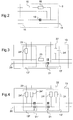
- the device comprises a housing 1 containing an electronic central unit 2, a power transmission module 3 and, if necessary, a power supply module 4 which are both connected to the central unit 2.
- the unit Central 2 comprises, in a conventional manner, in particular a processor and one or more memories containing an operating program executed by the processor to ensure the operation of the device.
- the power supply module 4 comprises a DC / DC converter arranged to supply, to the central unit 2, to the transmission module 3 and to the other components of the device, the voltages necessary for their operation.
- the transmission module 3 and the power supply module 4 are connected to a switching element 5 which is itself connected to a connector 6 for connection to an external power supply unit 7 provided with a connector 8 and a connector 9.
- An electrical cable 10 is connected to the connectors 6 and 8.
- the cable 10 is a conventional two-wire cable, for example of the coaxial type, and the connectors 6, 8 are two-pole connectors.
- the connector 9 is connected to a cable 11 for connection to the power supply network 100 supplying the alternating power supply current required to power the device and the data signals superimposed on the current.
- the external power supply unit 7 comprises an AC / DC converter 12 for transforming the AC supply current into a continuous supply current and lowering its voltage.
- the converter 12 is connected to the connectors 8 and 9 by a switching element 13.
- the switching elements 5 and 13 are three-port filters which make it possible to separate two frequency bands (the switch members are more precisely designated by the word "diplexer” in the jargon of the technical field concerned because they ensure multiplexing on two frequencies: the frequency of the supply current and the carrier frequency of the data signals).
- the switch members are thus arranged to separate the feed stream and the data signal.
- the switching member 5 comprises a first line 14 connected to the connector 6 and therefore to the cable 11 and to which are connected a second line 15 connected to the power supply module 4 and a third line 16 connected to the transmission module 3.
- the second line 15 is equipped with a power frequency filter 18 and the third line 16 is equipped with a carrier frequency filter 19.
- the power frequency filter 18 is an inductance mounted on one of the two conductors forming the second line 15 and the carrier frequency filter 19 is a capacitor mounted on one of the two conductors forming the third line 16.
- the switching member 5 is thus arranged to bring the supply current to the power supply module 4 and the signal data to the transmission module 3.
- the switching member 13 also comprises an AC diplexer 13 'on the input side of the converter 12 and a DC diplexer 13' on the output side of the converter 12.
- the switching member 13 comprises a branch line 20 connecting the connector 8 to the connector 9 and incorporating a carrier frequency filter generally designated 21.
- the converter 12 is connected to the branch line 20 on either side of the carrier frequency filter 21 by an input line 22 and an output line 23 of the converter 12.
- the switching element 13 comprises a power frequency filter 24 'mounted on one of the two connectors forming the input line 22 and a 24 "power frequency filter mounted on one of the two connectors forming the output line 23.
- the power frequency filter 24 ', 24" is an inductor and the carrier frequency filter 21 is a capacitor mounted on each of the two conductors forming the branch line 20.
- An inductor 25 is mounted on one of the conductors of the branch line 20 between the carrier frequency filter 21 and the line of output 23.
- the switching member 13 is thus arranged to extract and derive the data signal with respect to the converter 12: the data signal transits on the branch line 20 without passing through the converter 12 and is superimposed on the current d transformed (i.e. continuous) power supply at the output of the converter 12 in the direction of the reception of the data signals by the device.
- the data signals transit from the transmission module 3 to the power supply network via the switching element 5, the connector 6, the cable 10, the connector 8, the branch line 21, the switching member 13, and the connector 9.
- the inductance of the power frequency filters 24 has a minimum value of 160 ⁇ Hy and the capacitors forming the carrier frequency filters 21 have a maximum capacity of 2 nF.
- the inductance 25 has a value of approximately 11 ⁇ Hy so as to create a resonance with the capacitors forming the carrier frequency filters 21.
- the branch line 20 connecting the connector 8 to the connector 9 incorporates two carrier frequency filters 21 ', 21 "connected in series on each of the two conductors forming the line 20.
- circuit may be different from those described. Any electronic component suitable for performing one of the functions indicated may be substituted for the component mentioned in the description in relation to this function. Filters can be different components from each other.
- each conductor may be equipped with an inductor 24 or 25.
- the capacitors may be replaced by other passive filters or by active filters.
- an inductance on each line is sufficient to constitute the carrier frequency filters.
- the central processing unit may include the transmission module and the power supply module, or be separated from them ...
- the power supply module may be omitted if the power from the power supply has adequate characteristics for its power supply. food.
- the connector 8 can be omitted, the cable 10 coming directly from the power supply.
- the power supply can be arranged to be connected directly to the wall socket without cable.
Landscapes
- Engineering & Computer Science (AREA)
- Power Engineering (AREA)
- Computer Networks & Wireless Communication (AREA)
- Signal Processing (AREA)
- Cable Transmission Systems, Equalization Of Radio And Reduction Of Echo (AREA)
Claims (6)
- Vorrichtung, umfassend einerseits ein Gehäuse (1), das eine elektronische Zentraleinheit (2) enthält, und andererseits einen externen Versorgungsblock (7), der mit der Zentraleinheit über ein elektrisches Kabel (10) verbunden und mit einem Verbindungselement (9, 11) zur Verbindung mit einem Versorgungsnetz (100) versehen ist, das einen Wechselstrom und ein überlagertes Datensignal liefert, sowie mit einem Konverter (12) zum Umwandeln des Wechselstroms in einen Gleichstrom, dadurch gekennzeichnet, dass das Gehäuse ein Datenübertragungsmodul (3) zur Datenübertragung mittels Trägerstrom umfasst, dass der Konverter mit dem Verbindungselement (9, 11) und dem elektrischen Kabel (10) über ein erstes Weichenelement (13) verbunden ist, das das Datensignal extrahiert und in Bezug auf den Konverter ableitet, und dass das Modul und die Zentraleinheit mit dem elektrischen Kabel über ein zweites Weichenelement (5) verbunden sind, um den umgewandelten Versorgungsstrom und das Datensignal zu trennen und den Versorgungsstrom zur Zentraleinheit und das Datensignal zum Übertragungsmodul zu leiten, wobei das erste Weichenelement (13) eine Abzweigleitung (20) umfasst, die das Verbindungselement (9, 11) mit dem elektrischen Kabel (10) verbindet und ein Trägerfrequenzfilter (21) aufnimmt, wobei der Konverter (12) mit der Abzweigleitung zu beiden Seiten des Trägerfrequenzfilters über eine Eingangsleitung (22) und eine Ausgangsleitung (23) des Konverters verbunden ist, wobei das Weichenelement Leistungsfrequenzfilter (24', 24") umfasst, die auf der Eingangsleitung bzw. der Ausgangsleitung angebracht sind.
- Vorrichtung nach Anspruch 1, bei der mindestens eine Induktivität (25) auf der Abzweigleitung (20) zwischen dem Trägerfrequenzfilter (21) und der Ausgangsleitung (23) angebracht ist.
- Vorrichtung nach Anspruch 1, bei der das zweite Weichenelement (3) eine erste Leitung (14) umfasst, die mit dem elektrischen Kabel (10) verbunden und an die eine zweite Leitung (15) angeschlossen ist, die mit der Zentraleinheit verbunden ist, sowie eine dritte Leitung, die mit dem Übertragungsmodul (5) verbunden ist, wobei die zweite Leitung mit einem Leistungsfrequenzfilter (18) ausgestattet ist und die dritte Leitung mit einem Trägerfrequenzfilter (19) ausgestattet ist.
- Vorrichtung nach einem der vorhergehenden Ansprüche, bei der mindestens eines der Trägerfrequenzfilter (19, 21) ein passives Filter, wie z. B. ein Kondensator, ist.
- Vorrichtung nach einem der vorhergehenden Ansprüche, bei der mindestens eines der Leistungsfrequenzfilter eine Induktivität ist.
- Vorrichtung nach einem der vorhergehenden Ansprüche, bei der jede Leitung (14, 15, 16, 20, 22, 23) zwei Leiter umfasst, wobei ein Filter (18, 19, 21, 24', 24") auf mindestens einem der Leiter angebracht ist.
Applications Claiming Priority (2)
| Application Number | Priority Date | Filing Date | Title |
|---|---|---|---|
| FR0807337A FR2940561B1 (fr) | 2008-12-22 | 2008-12-22 | Dispositif electronique a courant porteur |
| PCT/FR2009/001416 WO2010072909A1 (fr) | 2008-12-22 | 2009-12-11 | Dispositif electronique a courant porteur |
Publications (2)
| Publication Number | Publication Date |
|---|---|
| EP2368329A1 EP2368329A1 (de) | 2011-09-28 |
| EP2368329B1 true EP2368329B1 (de) | 2019-03-13 |
Family
ID=40888220
Family Applications (1)
| Application Number | Title | Priority Date | Filing Date |
|---|---|---|---|
| EP09801226.3A Active EP2368329B1 (de) | 2008-12-22 | 2009-12-11 | Elektronische vorrichtung zur netzleitungsübertragung |
Country Status (6)
| Country | Link |
|---|---|
| US (1) | US9059783B2 (de) |
| EP (1) | EP2368329B1 (de) |
| CN (1) | CN102265522B (de) |
| BR (1) | BRPI0922545B1 (de) |
| FR (1) | FR2940561B1 (de) |
| WO (1) | WO2010072909A1 (de) |
Families Citing this family (5)
| Publication number | Priority date | Publication date | Assignee | Title |
|---|---|---|---|---|
| CN102621946B (zh) * | 2012-03-07 | 2014-09-17 | 冶金自动化研究设计院 | 一种基于Lonworks电力载波通讯的智能控制装置 |
| FR3028695B1 (fr) * | 2014-11-19 | 2017-12-22 | Pellenc Sa | Systeme et procede de communication bidirectionnelle et simultanee. |
| FR3062541A1 (fr) * | 2017-02-01 | 2018-08-03 | Agath | Dispositif multimedia avec reception et transmission de donnees par courants porteurs en ligne (cpl) |
| US11903123B1 (en) * | 2021-03-10 | 2024-02-13 | Marvell Asia Pte Ltd | Common-mode filtering for converting differential signaling to single-ended signaling |
| CN113271122B (zh) * | 2021-04-28 | 2023-03-31 | 厦门盈趣科技股份有限公司 | 一种包含纯净低压电力线载波传输网络的轨道电源 |
Citations (1)
| Publication number | Priority date | Publication date | Assignee | Title |
|---|---|---|---|---|
| US20020080010A1 (en) * | 2000-12-22 | 2002-06-27 | George Zhang | Power line communications network device for DC powered computer |
Family Cites Families (4)
| Publication number | Priority date | Publication date | Assignee | Title |
|---|---|---|---|---|
| JP2003258690A (ja) * | 2002-03-05 | 2003-09-12 | Alps Electric Co Ltd | 電力搬送用モデム |
| FR2871005B1 (fr) * | 2004-06-01 | 2006-12-15 | Courant Multi Media | Serveur d'impression courants porteurs |
| US7286026B2 (en) * | 2004-09-02 | 2007-10-23 | Avago Technologies Ecbu Ip (Singapore) Pte. Ltd. | Serial signal injection using capacitive and transformer couplings for power line communications |
| US8040235B2 (en) * | 2005-04-08 | 2011-10-18 | Panasonic Corporation | Relay apparatus and electric appliance |
-
2008
- 2008-12-22 FR FR0807337A patent/FR2940561B1/fr not_active Expired - Fee Related
-
2009
- 2009-12-11 US US13/141,194 patent/US9059783B2/en active Active
- 2009-12-11 BR BRPI0922545-5A patent/BRPI0922545B1/pt active IP Right Grant
- 2009-12-11 EP EP09801226.3A patent/EP2368329B1/de active Active
- 2009-12-11 CN CN200980153003.6A patent/CN102265522B/zh not_active Expired - Fee Related
- 2009-12-11 WO PCT/FR2009/001416 patent/WO2010072909A1/fr not_active Ceased
Patent Citations (1)
| Publication number | Priority date | Publication date | Assignee | Title |
|---|---|---|---|---|
| US20020080010A1 (en) * | 2000-12-22 | 2002-06-27 | George Zhang | Power line communications network device for DC powered computer |
Also Published As
| Publication number | Publication date |
|---|---|
| FR2940561A1 (fr) | 2010-06-25 |
| US20110248774A1 (en) | 2011-10-13 |
| CN102265522B (zh) | 2014-12-03 |
| CN102265522A (zh) | 2011-11-30 |
| FR2940561B1 (fr) | 2017-06-16 |
| EP2368329A1 (de) | 2011-09-28 |
| US9059783B2 (en) | 2015-06-16 |
| BRPI0922545A2 (pt) | 2010-07-01 |
| WO2010072909A1 (fr) | 2010-07-01 |
| BRPI0922545B1 (pt) | 2021-06-01 |
Similar Documents
| Publication | Publication Date | Title |
|---|---|---|
| EP0583843B1 (de) | Kabelverteilungssystem für Fernsehsignale und Anordnung von Elementen um ein solches System zu bauen | |
| EP0781048A1 (de) | Kabelfernsehverteilungssystem | |
| US20100246648A1 (en) | External AC-DC Coupling for Communication Interfaces | |
| FR2606234A1 (fr) | Systeme de radio bus | |
| WO2010072909A1 (fr) | Dispositif electronique a courant porteur | |
| EP2326026A1 (de) | Trägerstromsystem, das direkt an einen Gleichstromenergiebus angeschlossen ist | |
| EP0583830A1 (de) | Gehäuse zur Verbindung zu einem Verteilungssystem von Fernsehsignalen und Verteilungssystem mit Selektionsmitteln | |
| EP1374437A1 (de) | Schnelles datenübertragungssystem zu einem digitalen endgerät | |
| EP1554824A1 (de) | Vorrichtung zum verteilen von funksignalen und empfangssystem, das eine solche vorrichtung enthält | |
| FR2513477A1 (fr) | Equipement electrique du type comprenant plusieurs cartes de circuit imprime raccordees a un plan de connexions | |
| EP1632084B1 (de) | Impedanzadapter für einen übertragungskanal mit hoher bandbreite eines kupferverdrahteten terminal-systems | |
| EP2820766B1 (de) | Modulations-demodulations-vorrichtung zum senden und empfangen von daten auf einer hochspannungsleitung | |
| EP3688896B1 (de) | Vorrichtung zum empfangen von signalen, die von einer satellitenantenne erfasst wurden | |
| CA2324430A1 (fr) | Dispositif et boitier pour raccordement a un reseau local | |
| EP2820750A2 (de) | Leistungsversorgungssystem | |
| FR2638927A1 (fr) | Systeme d'amplification pour teledistribution | |
| FR2762165A1 (fr) | Circuit de ligne d'equipement serie de telephone | |
| WO2001057891A1 (fr) | Dispositif pour le couplage, avec isolation galvanique, de type 'a coupure certaine' | |
| FR2977415A1 (fr) | Reseau d'interconnexion d'equipements pour vehicules par courants porteurs en ligne | |
| FR2969872A1 (fr) | Ensemble de telecommunication multiservice et dispositif d'emission/reception d'ondes radioelectriques d'un tel ensemble. | |
| FR2923122A1 (fr) | Systeme de transmission audiovisuelle dans un reseau vdi | |
| EP2793474A1 (de) | Kaskadierbare Mehrfamilienhaus-Satellitensignalverteilungsvorrichtung | |
| FR2843254A1 (fr) | Dispositif et procede de couplage entre un modem et un reseau de distribution electrique delimite. | |
| EP1493228A1 (de) | Anwendungsspezifische integrierte schaltung für eine zum entkoppeln von xdsl-kanälen versendete tiefpassfiltereinrichtung | |
| EP0958669A1 (de) | Elektroakustisches gerät mit abschirmungseinrichtung |
Legal Events
| Date | Code | Title | Description |
|---|---|---|---|
| PUAI | Public reference made under article 153(3) epc to a published international application that has entered the european phase |
Free format text: ORIGINAL CODE: 0009012 |
|
| 17P | Request for examination filed |
Effective date: 20110617 |
|
| AK | Designated contracting states |
Kind code of ref document: A1 Designated state(s): AT BE BG CH CY CZ DE DK EE ES FI FR GB GR HR HU IE IS IT LI LT LU LV MC MK MT NL NO PL PT RO SE SI SK SM TR |
|
| DAX | Request for extension of the european patent (deleted) | ||
| STAA | Information on the status of an ep patent application or granted ep patent |
Free format text: STATUS: EXAMINATION IS IN PROGRESS |
|
| 17Q | First examination report despatched |
Effective date: 20171204 |
|
| GRAP | Despatch of communication of intention to grant a patent |
Free format text: ORIGINAL CODE: EPIDOSNIGR1 |
|
| STAA | Information on the status of an ep patent application or granted ep patent |
Free format text: STATUS: GRANT OF PATENT IS INTENDED |
|
| INTG | Intention to grant announced |
Effective date: 20180927 |
|
| GRAS | Grant fee paid |
Free format text: ORIGINAL CODE: EPIDOSNIGR3 |
|
| GRAA | (expected) grant |
Free format text: ORIGINAL CODE: 0009210 |
|
| STAA | Information on the status of an ep patent application or granted ep patent |
Free format text: STATUS: THE PATENT HAS BEEN GRANTED |
|
| AK | Designated contracting states |
Kind code of ref document: B1 Designated state(s): AT BE BG CH CY CZ DE DK EE ES FI FR GB GR HR HU IE IS IT LI LT LU LV MC MK MT NL NO PL PT RO SE SI SK SM TR |
|
| REG | Reference to a national code |
Ref country code: GB Ref legal event code: FG4D Free format text: NOT ENGLISH |
|
| RIN1 | Information on inventor provided before grant (corrected) |
Inventor name: HERGAULT, STEPHANE |
|
| REG | Reference to a national code |
Ref country code: CH Ref legal event code: EP Ref country code: AT Ref legal event code: REF Ref document number: 1109096 Country of ref document: AT Kind code of ref document: T Effective date: 20190315 |
|
| REG | Reference to a national code |
Ref country code: IE Ref legal event code: FG4D Free format text: LANGUAGE OF EP DOCUMENT: FRENCH |
|
| REG | Reference to a national code |
Ref country code: DE Ref legal event code: R096 Ref document number: 602009057447 Country of ref document: DE |
|
| REG | Reference to a national code |
Ref country code: NL Ref legal event code: MP Effective date: 20190313 |
|
| REG | Reference to a national code |
Ref country code: LT Ref legal event code: MG4D |
|
| PG25 | Lapsed in a contracting state [announced via postgrant information from national office to epo] |
Ref country code: SE Free format text: LAPSE BECAUSE OF FAILURE TO SUBMIT A TRANSLATION OF THE DESCRIPTION OR TO PAY THE FEE WITHIN THE PRESCRIBED TIME-LIMIT Effective date: 20190313 Ref country code: LT Free format text: LAPSE BECAUSE OF FAILURE TO SUBMIT A TRANSLATION OF THE DESCRIPTION OR TO PAY THE FEE WITHIN THE PRESCRIBED TIME-LIMIT Effective date: 20190313 Ref country code: FI Free format text: LAPSE BECAUSE OF FAILURE TO SUBMIT A TRANSLATION OF THE DESCRIPTION OR TO PAY THE FEE WITHIN THE PRESCRIBED TIME-LIMIT Effective date: 20190313 Ref country code: NO Free format text: LAPSE BECAUSE OF FAILURE TO SUBMIT A TRANSLATION OF THE DESCRIPTION OR TO PAY THE FEE WITHIN THE PRESCRIBED TIME-LIMIT Effective date: 20190613 |
|
| PG25 | Lapsed in a contracting state [announced via postgrant information from national office to epo] |
Ref country code: BG Free format text: LAPSE BECAUSE OF FAILURE TO SUBMIT A TRANSLATION OF THE DESCRIPTION OR TO PAY THE FEE WITHIN THE PRESCRIBED TIME-LIMIT Effective date: 20190613 Ref country code: GR Free format text: LAPSE BECAUSE OF FAILURE TO SUBMIT A TRANSLATION OF THE DESCRIPTION OR TO PAY THE FEE WITHIN THE PRESCRIBED TIME-LIMIT Effective date: 20190614 Ref country code: LV Free format text: LAPSE BECAUSE OF FAILURE TO SUBMIT A TRANSLATION OF THE DESCRIPTION OR TO PAY THE FEE WITHIN THE PRESCRIBED TIME-LIMIT Effective date: 20190313 Ref country code: NL Free format text: LAPSE BECAUSE OF FAILURE TO SUBMIT A TRANSLATION OF THE DESCRIPTION OR TO PAY THE FEE WITHIN THE PRESCRIBED TIME-LIMIT Effective date: 20190313 Ref country code: HR Free format text: LAPSE BECAUSE OF FAILURE TO SUBMIT A TRANSLATION OF THE DESCRIPTION OR TO PAY THE FEE WITHIN THE PRESCRIBED TIME-LIMIT Effective date: 20190313 |
|
| REG | Reference to a national code |
Ref country code: AT Ref legal event code: MK05 Ref document number: 1109096 Country of ref document: AT Kind code of ref document: T Effective date: 20190313 |
|
| PG25 | Lapsed in a contracting state [announced via postgrant information from national office to epo] |
Ref country code: PT Free format text: LAPSE BECAUSE OF FAILURE TO SUBMIT A TRANSLATION OF THE DESCRIPTION OR TO PAY THE FEE WITHIN THE PRESCRIBED TIME-LIMIT Effective date: 20190713 Ref country code: RO Free format text: LAPSE BECAUSE OF FAILURE TO SUBMIT A TRANSLATION OF THE DESCRIPTION OR TO PAY THE FEE WITHIN THE PRESCRIBED TIME-LIMIT Effective date: 20190313 Ref country code: CZ Free format text: LAPSE BECAUSE OF FAILURE TO SUBMIT A TRANSLATION OF THE DESCRIPTION OR TO PAY THE FEE WITHIN THE PRESCRIBED TIME-LIMIT Effective date: 20190313 Ref country code: ES Free format text: LAPSE BECAUSE OF FAILURE TO SUBMIT A TRANSLATION OF THE DESCRIPTION OR TO PAY THE FEE WITHIN THE PRESCRIBED TIME-LIMIT Effective date: 20190313 Ref country code: EE Free format text: LAPSE BECAUSE OF FAILURE TO SUBMIT A TRANSLATION OF THE DESCRIPTION OR TO PAY THE FEE WITHIN THE PRESCRIBED TIME-LIMIT Effective date: 20190313 Ref country code: SK Free format text: LAPSE BECAUSE OF FAILURE TO SUBMIT A TRANSLATION OF THE DESCRIPTION OR TO PAY THE FEE WITHIN THE PRESCRIBED TIME-LIMIT Effective date: 20190313 Ref country code: IT Free format text: LAPSE BECAUSE OF FAILURE TO SUBMIT A TRANSLATION OF THE DESCRIPTION OR TO PAY THE FEE WITHIN THE PRESCRIBED TIME-LIMIT Effective date: 20190313 |
|
| PG25 | Lapsed in a contracting state [announced via postgrant information from national office to epo] |
Ref country code: PL Free format text: LAPSE BECAUSE OF FAILURE TO SUBMIT A TRANSLATION OF THE DESCRIPTION OR TO PAY THE FEE WITHIN THE PRESCRIBED TIME-LIMIT Effective date: 20190313 Ref country code: SM Free format text: LAPSE BECAUSE OF FAILURE TO SUBMIT A TRANSLATION OF THE DESCRIPTION OR TO PAY THE FEE WITHIN THE PRESCRIBED TIME-LIMIT Effective date: 20190313 |
|
| REG | Reference to a national code |
Ref country code: DE Ref legal event code: R097 Ref document number: 602009057447 Country of ref document: DE |
|
| PG25 | Lapsed in a contracting state [announced via postgrant information from national office to epo] |
Ref country code: IS Free format text: LAPSE BECAUSE OF FAILURE TO SUBMIT A TRANSLATION OF THE DESCRIPTION OR TO PAY THE FEE WITHIN THE PRESCRIBED TIME-LIMIT Effective date: 20190713 Ref country code: AT Free format text: LAPSE BECAUSE OF FAILURE TO SUBMIT A TRANSLATION OF THE DESCRIPTION OR TO PAY THE FEE WITHIN THE PRESCRIBED TIME-LIMIT Effective date: 20190313 |
|
| PLBE | No opposition filed within time limit |
Free format text: ORIGINAL CODE: 0009261 |
|
| STAA | Information on the status of an ep patent application or granted ep patent |
Free format text: STATUS: NO OPPOSITION FILED WITHIN TIME LIMIT |
|
| PG25 | Lapsed in a contracting state [announced via postgrant information from national office to epo] |
Ref country code: DK Free format text: LAPSE BECAUSE OF FAILURE TO SUBMIT A TRANSLATION OF THE DESCRIPTION OR TO PAY THE FEE WITHIN THE PRESCRIBED TIME-LIMIT Effective date: 20190313 |
|
| 26N | No opposition filed |
Effective date: 20191216 |
|
| PG25 | Lapsed in a contracting state [announced via postgrant information from national office to epo] |
Ref country code: SI Free format text: LAPSE BECAUSE OF FAILURE TO SUBMIT A TRANSLATION OF THE DESCRIPTION OR TO PAY THE FEE WITHIN THE PRESCRIBED TIME-LIMIT Effective date: 20190313 |
|
| PG25 | Lapsed in a contracting state [announced via postgrant information from national office to epo] |
Ref country code: TR Free format text: LAPSE BECAUSE OF FAILURE TO SUBMIT A TRANSLATION OF THE DESCRIPTION OR TO PAY THE FEE WITHIN THE PRESCRIBED TIME-LIMIT Effective date: 20190313 |
|
| REG | Reference to a national code |
Ref country code: CH Ref legal event code: PL |
|
| REG | Reference to a national code |
Ref country code: BE Ref legal event code: MM Effective date: 20191231 |
|
| PG25 | Lapsed in a contracting state [announced via postgrant information from national office to epo] |
Ref country code: MC Free format text: LAPSE BECAUSE OF FAILURE TO SUBMIT A TRANSLATION OF THE DESCRIPTION OR TO PAY THE FEE WITHIN THE PRESCRIBED TIME-LIMIT Effective date: 20190313 |
|
| PG25 | Lapsed in a contracting state [announced via postgrant information from national office to epo] |
Ref country code: LU Free format text: LAPSE BECAUSE OF NON-PAYMENT OF DUE FEES Effective date: 20191211 Ref country code: IE Free format text: LAPSE BECAUSE OF NON-PAYMENT OF DUE FEES Effective date: 20191211 |
|
| PG25 | Lapsed in a contracting state [announced via postgrant information from national office to epo] |
Ref country code: LI Free format text: LAPSE BECAUSE OF NON-PAYMENT OF DUE FEES Effective date: 20191231 Ref country code: BE Free format text: LAPSE BECAUSE OF NON-PAYMENT OF DUE FEES Effective date: 20191231 Ref country code: CH Free format text: LAPSE BECAUSE OF NON-PAYMENT OF DUE FEES Effective date: 20191231 |
|
| PG25 | Lapsed in a contracting state [announced via postgrant information from national office to epo] |
Ref country code: CY Free format text: LAPSE BECAUSE OF FAILURE TO SUBMIT A TRANSLATION OF THE DESCRIPTION OR TO PAY THE FEE WITHIN THE PRESCRIBED TIME-LIMIT Effective date: 20190313 |
|
| PG25 | Lapsed in a contracting state [announced via postgrant information from national office to epo] |
Ref country code: MT Free format text: LAPSE BECAUSE OF FAILURE TO SUBMIT A TRANSLATION OF THE DESCRIPTION OR TO PAY THE FEE WITHIN THE PRESCRIBED TIME-LIMIT Effective date: 20190313 Ref country code: HU Free format text: LAPSE BECAUSE OF FAILURE TO SUBMIT A TRANSLATION OF THE DESCRIPTION OR TO PAY THE FEE WITHIN THE PRESCRIBED TIME-LIMIT; INVALID AB INITIO Effective date: 20091211 |
|
| PG25 | Lapsed in a contracting state [announced via postgrant information from national office to epo] |
Ref country code: MK Free format text: LAPSE BECAUSE OF FAILURE TO SUBMIT A TRANSLATION OF THE DESCRIPTION OR TO PAY THE FEE WITHIN THE PRESCRIBED TIME-LIMIT Effective date: 20190313 |
|
| PGFP | Annual fee paid to national office [announced via postgrant information from national office to epo] |
Ref country code: DE Payment date: 20241121 Year of fee payment: 16 |
|
| PGFP | Annual fee paid to national office [announced via postgrant information from national office to epo] |
Ref country code: GB Payment date: 20241122 Year of fee payment: 16 |
|
| PGFP | Annual fee paid to national office [announced via postgrant information from national office to epo] |
Ref country code: FR Payment date: 20241121 Year of fee payment: 16 |