EP2368458B1 - Seating safety device - Google Patents
Seating safety device Download PDFInfo
- Publication number
- EP2368458B1 EP2368458B1 EP11159838A EP11159838A EP2368458B1 EP 2368458 B1 EP2368458 B1 EP 2368458B1 EP 11159838 A EP11159838 A EP 11159838A EP 11159838 A EP11159838 A EP 11159838A EP 2368458 B1 EP2368458 B1 EP 2368458B1
- Authority
- EP
- European Patent Office
- Prior art keywords
- chair
- safety device
- side barriers
- barrier
- seating
- Prior art date
- Legal status (The legal status is an assumption and is not a legal conclusion. Google has not performed a legal analysis and makes no representation as to the accuracy of the status listed.)
- Not-in-force
Links
- 230000004888 barrier function Effects 0.000 claims description 120
- 239000004744 fabric Substances 0.000 description 9
- 239000000463 material Substances 0.000 description 5
- 238000000034 method Methods 0.000 description 5
- 239000011120 plywood Substances 0.000 description 3
- 239000007787 solid Substances 0.000 description 3
- 238000005553 drilling Methods 0.000 description 2
- 239000002184 metal Substances 0.000 description 2
- 241001465754 Metazoa Species 0.000 description 1
- 241000139306 Platt Species 0.000 description 1
- 239000000969 carrier Substances 0.000 description 1
- 230000001419 dependent effect Effects 0.000 description 1
- 230000000694 effects Effects 0.000 description 1
- 239000013013 elastic material Substances 0.000 description 1
- 230000003090 exacerbative effect Effects 0.000 description 1
- 238000007689 inspection Methods 0.000 description 1
- 239000002023 wood Substances 0.000 description 1
Images


Classifications
-
- A—HUMAN NECESSITIES
- A61—MEDICAL OR VETERINARY SCIENCE; HYGIENE
- A61G—TRANSPORT, PERSONAL CONVEYANCES, OR ACCOMMODATION SPECIALLY ADAPTED FOR PATIENTS OR DISABLED PERSONS; OPERATING TABLES OR CHAIRS; CHAIRS FOR DENTISTRY; FUNERAL DEVICES
- A61G5/00—Chairs or personal conveyances specially adapted for patients or disabled persons, e.g. wheelchairs
- A61G5/10—Parts, details or accessories
- A61G5/14—Standing-up or sitting-down aids
Definitions
- This invention relates to a safety device for seating and to a chair or the like fitted with a seating safety device.
- the invention relates to a safety device for a recline and rise chair.
- chair In the specification reference is made to a chair, but it should be understood that the reference to chair can also be taken to mean other seating furniture, such as a settee for use by more than one person.
- a rise and recline chair which is controllable by a user, typically by means of a electric or pneumatic motors, to tilt forwards into a risen position, which assists the user in the standing up from a seated position.
- a rise position the seat tilts forwards so that a seat portion moves from a generally horizontal alignment to a forward tipping alignment.
- This type of chair also will typically recline i.e. tilt backwards to provide a more recumbent position for a user of the chair.
- the rise and recline chair typically has a control panel which may be a unit with a control wire extending from beneath the chair which a user can use to cause the chair to rise or recline.
- a seating safety device comprising at least first and second side barriers, wherein the side barriers are adapted to be received inboard of respective side faces of a chair to which the seating safety device is, in use, to be fitted, wherein the first and second side barriers are adapted to be received in respective openings in arms of a chair to which the seating safety device is, in use, to be fitted.
- the seating safety device preferably incorporates a front barrier.
- the seating safety device preferably incorporates a rear barrier.
- At least one of the first and second side and front barriers is preferably a substantially rigid barrier.
- At least one of the front and rear barriers may be a flexible barrier.
- the openings in the arms are preferably slot openings, preferably located in bottom sides of the arms.
- the first and second side barriers are adapted to be secured to a base frame of the chair.
- the base frame preferably supports a remainder of the chair and preferably, in use, remains in contact with a support surface on which the chair is located.
- the front barrier may be adapted to be secured to the base frame.
- An upper region, or edge, of the front barrier may be adapted to be secured to a lower front region, or edge, of the chair.
- the rear barrier may be adapted to be secured at a lower region, or edge, thereof to the base frame.
- An upper region, or edge, of the rear barrier may be adapted to be secured to a lower rear region, or edge, of the chair.
- the first and second side barriers may be adapted to be movably supported with respect to the base frame.
- the first and second side barriers may be adapted to be slidable with respect to the base frame.
- the first and second side barriers may each include a slot, preferably a slot adapted to receive at least one projection of the base frame. Engagement of the slot and projection preferably allows a sliding movement of the side barriers with respect to the base frame. The sliding movement is preferably, in use, caused by movement of the chair against the side barriers.
- the side barriers are preferably shaped to prevent snagging of the chair on the side barriers when the chair moves.
- a sloping top edge is preferably provided for that purpose.
- a chair comprising a seat portion, first and second arms and a seating safety device comprising at least first and second side barriers, wherein the side barriers are received inboard of respective side faces of the arms of the chair.
- the seating safety device preferably incorporates a front barrier.
- the seating safety device preferably incorporates a rear barrier.
- At least one of the first and second side and front barriers is preferably a substantially rigid barrier.
- At least one of the front and rear barriers may be a flexible barrier.
- the first and second side barriers are preferably received in respective openings in arms of the chair.
- the openings in the arms are preferably slot openings, preferably located in bottom sides of the arms.
- the first and second side barriers are secured to a base frame of the chair.
- the base frame preferably supports a remainder of the chair and preferably, in use, remains in contact with a support surface on which the chair is located.
- the front barrier is preferably secured to the base frame.
- An upper region, or edge, of the front barrier may be secured to a lower front region, or edge, of the chair.
- the rear barrier may be secured at a lower region, or edge, thereof to the base frame.
- An upper region, or edge, of the rear barrier may secured to a lower rear region, or edge, of the chair.
- the first and second side barriers may be movably supported with respect to the base frame.
- the first and second side barriers may be slidable with respect to the base frame.
- the first and second side barriers may each include a slot, in which is received at least one projection of the base frame. Engagement of the slot and projection preferably allows a sliding movement of the side barriers with respect to the base frame. The sliding movement is preferably, in use, caused by movement of the chair against the side barriers.
- the side barriers are preferably shaped to prevent snagging of the chair on the side barriers when the chair moves.
- a sloping top edge is preferably provided for that purpose.
- the invention extends to a kit of parts incorporating a seating safety device as described in the first aspect and fixing means for fixing the seating safety device to a chair.
- the fixing means may include batons adapted to be fixed between parts of the safety device and a chair to which it is to be fitted.
- the fixing means may include screws and/or bolts for fixing/holding the batons in position.
- Figures 1 and 1a show the disadvantages mentioned above in relation to prior art rise and recline chairs. It can clearly be seen that when a chair 10 is in the risen position, as is the case in Figures 1 and 1a , a large gap 12 is revealed beneath the chair. The danger of a pet or child moving into this gap, or an adult having part of their body in the gap gives rise to a potential danger when the chair 10 is moved to its a normal seating position with a seat portion 14 of the chair being in a generally horizontal position.
- a base frame 16 of the chair is clearly visible, the chair 10 sits on the base frame which remains generally stationary with respect to the floor when the chair 10 is being adjusted.
- the base frame 16 includes a front support bar 18 and a rear support bar 20 with joining support bars 22 extending therebetween.
- FIG 2 shows the same type of chair 14 as shown in Figure 1 supported on the same type of base frame 16 as that shown in Figure 1 .
- the chair is provided with a safety barrier 24 which is exposed when the chair 10 is tilted forward in the risen position as shown in Figure 2 or is in a reclined position.
- the safety barrier 24 comprises fabric covered solid side barriers 26a, 26b, a fabric covered solid or fabric front barrier 28 and a fabric rear barrier 30.
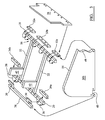
- FIG. 3 shows more detail of the base frame 16 and parts of the safety barrier 24, together with attachment sections for attaching the safety barrier 24 to the base frame 16.
- FIG. 3 shows a partially exploded view of the safety barrier 24 and base frame 16.
- Wooden batons 32a, 32b and 32c are attached to the base frame 16 at the positions shown by arrows inside the front bar 18.
- wooden batons are described herein, metal batons or plates could be used instead, in which case they may be attached to the base frame by self drilling metal screws.
- the batons have lengths of 85mm, 370mm and 85mm respectively, with a thickness of approximately 25mm.
- the batons 32a, 32b, 32c are screwed to the front bar 18.
- front barrier 28 may be secured to the front bar 18 directly using self drilling screws.
- the front barrier 28 is typically made of plywood and is 12mm thick, with a length along its base of 530mm, a full height of 275mm with 40mm steps in at either side at a height of 100mm.
- a fabric piece may also be stapled to the top of the front barrier 28 and a lower part of the seat portion 14 of the chair.
- Batons 34a and 34b are secured to inside portions of the rear bar 20 of the base frame 16 at the locations shown in Figure 3 .
- a baton 36 is secured to an outside portion of the rear bar 20 by tabs.
- the baton 36 is secured by tabs 39 to trolley wheel carriers 38 that are secured to the rear bar 20.
- Outer ends of the baton 32a, the baton 34a and the baton 36 are aligned generally flush with ends of the front and rear bars 18 and 20 to which they are attached. Openings are shown in the ends of the batons 32a, 34a and 36, which openings receive fixings for the side barriers 26a and 26b. Corresponding openings are shown in the side barrier 26b.
- a cutaway 40 is provided in the base of the side barriers 26a, 26b to allow the rear bar 20 to extend therethrough.
- the baton 36 has a length of 590mm with openings on the tabs 39 at centres spaced 570mm apart and is 25mm square in cross-section.
- the batons 34a,b measure 85mm by 25mm by 25mm.
- the side barriers 26a and 26b are typically made of plywood that is 9mm thick. The plywood is covered in upholstery material that matches the remainder of the chair 10.
- the side barrier 26a is secured to the opposite side of the framework 16 to the batons 32c, 34b and 36.
- mounting plates may extend across the ends of the front and rear bars 18 and 20, to which the side barriers 26a,b may be secured with screws along a lower edge thereof.
- Upstanding tabs 42 extend from the joining bars 22. The chair 10 and remainder of the framework and driving mechanism for the chair 10 is secured to the upstanding tabs 42.
- the rear barrier 30 is made of a fabric material that at its lower edge is wrapped around the rear baton 36 and secured with hook and loop fastener arrangement 31a, 31b.
- the At its upper edge the rear barrier 30 is secured to a baton (not shown) measuring 540mm by 25mm by 25mm attached to a lower rear edge of the chair 10.
- the top edge of the rear barrier may be held in place with a hook and loop fastener arrangement 33a,33b secured to a cross bar of the chair framework.
- the rear barrier 30, as shown in Figure 7 incorporates strips of stretch elastic material that is secured at upper sections of the left and right edges of the rear barrier 30 to cause the material to shorten and fold when the chair is in the lowered position, as will be described below.
- the rear barrier 30 measures 580mm wide by 680mm high. When in position, the front barrier 28 and side barriers 26a, 26b are in the location as shown in Figure 2 .
- the shape of the side barriers 26a, 26b has been chosen carefully so that the side barriers 26a/b do not foul with the chair 10 as it moves.
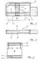
- a particular feature of the invention described herein is that the side barriers 26a,b are received within arms 46 of the chair 10, the structure of which is shown in Figures 5 and 6 .
- the arms 46 are made of a framework of wood.
- a particular feature of the arms 46 is that there is a slot opening 48 (see Figure 6 ) into which the side barriers 26a,b slide as the chair 10 is moved, as described below.
- the slot 48 is formed between side sections 50 and 51 of the arms 46.
- the side barriers 26a,b incorporate a cut-away section 40 at the lower edge thereof to accommodate the rear bar 20 of the base frame 16.
- a guide 53 extends from the side sections 51 to the upper part of the frame. The guide 53 is used to deter fouling of the side barriers 26a/b as they move into the slot 48, as described below.
- the side barrier 26b (shown in a dashed line) is in the position shown in Figure 5 , stowed within the slots 48 in the arms 46.
- Side barrier 26a will be in the same position in the other arm 46. In this position, only lower edges of the front and side barriers 28, 26a,b will be seen. Also, the rear barrier 30 will be hanging from a rear edge of the chair 10 and not under tension, slack material folds into the space beneath the chair.
- base frame and safety barrier 64 An alternative embodiment of base frame and safety barrier 64 is shown in Figure 4 . Many of the parts correspond to the embodiment mentioned above and like numerals have been used for the two embodiments, where appropriate.
- the embodiment shown in Figure 4 has different side barriers 56a,b which have a different profile.
- the side barriers 56a,b also incorporate a slot 58 through which project sliding bolts 60 that are secured to frame supports 62 that are in turn secured in the positions shown on the side of the joining bars 22 by means of a bolt on an underside of the frame supports 62.
- the cutaway section 64 prevents the side barriers 56 fouling with the rear bar 20 when there is lateral movement of the side barriers, 56a,b, as discussed below.
- the front bar 18 of the base frame 16 also incorporates a front projection bar 66, which has a corresponding wooden frame 68 for attachment of the front barrier 57, which in this example is a fabric barrier, similar to that of the rear barrier 30.
- the embodiment shown in Figure 4 incorporates a front barrier 69 that is made of fabric secured to the wooden frame 68 at its lower edge and to a front lower edge of the chair 10 at its upper edge.
- the front barrier 69 measures 530mm across by 650mm high.
- Elastic sections secured to the fabric of the front barrier 69 allow the material to expand or contract as the front of the chair 10 moves up and down with respect to the base frame 16.
- the embodiment of Figure 4 also incorporates a rear barrier 30 as described in relation to the first embodiment, but measuring 400mm across by 260 mm high.
- a significant advantage of the device shown herein is that the side barriers 26a,b and 56a,b are received within slots in arms 46 of the chair 10. This allows the arms 46 of the chairs to remain the outer most side parts of the chair at all times when the chair is raised or lowered, tilted or risen. This has considerable safety advantages over an external rigid barrier which would present at all times an upward facing gap between the barrier and chair which would be a trapping hazard.
Landscapes
- Health & Medical Sciences (AREA)
- Life Sciences & Earth Sciences (AREA)
- Animal Behavior & Ethology (AREA)
- General Health & Medical Sciences (AREA)
- Public Health (AREA)
- Veterinary Medicine (AREA)
- Chairs For Special Purposes, Such As Reclining Chairs (AREA)
Priority Applications (1)
| Application Number | Priority Date | Filing Date | Title |
|---|---|---|---|
| PL11159838T PL2368458T3 (pl) | 2010-03-25 | 2011-03-25 | Urządzenie bezpieczeństwa do foteli |
Applications Claiming Priority (1)
| Application Number | Priority Date | Filing Date | Title |
|---|---|---|---|
| GBGB1004959.1A GB201004959D0 (en) | 2010-03-25 | 2010-03-25 | Seating safety device |
Publications (2)
| Publication Number | Publication Date |
|---|---|
| EP2368458A1 EP2368458A1 (en) | 2011-09-28 |
| EP2368458B1 true EP2368458B1 (en) | 2013-03-20 |
Family
ID=42228280
Family Applications (1)
| Application Number | Title | Priority Date | Filing Date |
|---|---|---|---|
| EP11159838A Not-in-force EP2368458B1 (en) | 2010-03-25 | 2011-03-25 | Seating safety device |
Country Status (3)
| Country | Link |
|---|---|
| EP (1) | EP2368458B1 (pl) |
| GB (1) | GB201004959D0 (pl) |
| PL (1) | PL2368458T3 (pl) |
Families Citing this family (3)
| Publication number | Priority date | Publication date | Assignee | Title |
|---|---|---|---|---|
| US8308228B2 (en) | 2010-02-11 | 2012-11-13 | L & P Property Management Company | Zero-wall clearance linkage mechanism for a lifting recliner |
| US8944498B2 (en) | 2012-01-05 | 2015-02-03 | L & Property Management Company | Linkage mechanism for a dual-motor lifting recliner |
| US9050231B2 (en) | 2012-07-18 | 2015-06-09 | L&P Property Management Company | Seat-lift assembly |
Family Cites Families (4)
| Publication number | Priority date | Publication date | Assignee | Title |
|---|---|---|---|---|
| US3781060A (en) * | 1972-09-01 | 1973-12-25 | Kroehler Mfg Co | Safety guard for reclining chair and the like |
| US6702378B2 (en) * | 2001-02-08 | 2004-03-09 | L & P Property Management Company | Lift chair skirt |
| GB0119132D0 (en) * | 2001-08-03 | 2001-09-26 | Seminar Components Uk Ltd | Imrovements in and relating to adjustable chairs and beds |
| US20070096524A1 (en) * | 2005-11-01 | 2007-05-03 | Shang-Wei Chou | Corrective chair |
-
2010
- 2010-03-25 GB GBGB1004959.1A patent/GB201004959D0/en not_active Ceased
-
2011
- 2011-03-25 PL PL11159838T patent/PL2368458T3/pl unknown
- 2011-03-25 EP EP11159838A patent/EP2368458B1/en not_active Not-in-force
Also Published As
| Publication number | Publication date |
|---|---|
| PL2368458T3 (pl) | 2013-09-30 |
| GB201004959D0 (en) | 2010-05-12 |
| EP2368458A1 (en) | 2011-09-28 |
Similar Documents
| Publication | Publication Date | Title |
|---|---|---|
| US7722114B2 (en) | Zero gravity wall hugger recliner | |
| EP1411801B1 (en) | Improvements in and relating to adjustable chairs and beds | |
| US9730522B2 (en) | Headrest tilt mechanism | |
| CA2857310C (en) | Adjustable reclining chair | |
| US10405660B2 (en) | Adjustable furniture | |
| US20110062758A1 (en) | Item of Seating Furniture with Seat Depth Adjustment | |
| US7121627B2 (en) | Leg-rest extension | |
| KR20180020227A (ko) | 가구 부재를 위한 리클라이너 및 레그레스트 기구 | |
| CA2976305C (en) | Furniture member with legrest extension | |
| US20090302654A1 (en) | Chair With Tiltable Backrest | |
| US9888776B2 (en) | Seating/reclining furniture | |
| US3619004A (en) | Cantilever seat structure | |
| EP2368458A1 (en) | Seating safety device | |
| EP3051979A2 (en) | Lift-recliner chair | |
| US20220104627A1 (en) | Modular sofa with adjustable seat | |
| JP5432218B2 (ja) | 可搬式椅子 | |
| US20240251949A1 (en) | Theater chair | |
| JP5243566B2 (ja) | 椅子 | |
| JP2015089425A (ja) | フラップ天板付家具 | |
| US2430356A (en) | Theater chair | |
| KR101138348B1 (ko) | 예배용 접이식 장의자 | |
| US6776456B1 (en) | Gliding chair unit with cushioning members | |
| US2492111A (en) | Retracting type theater chair | |
| KR20210087520A (ko) | 시트 섀시 | |
| KR101746095B1 (ko) | 좌판 분리 및 쿠션 가능한 의자 |
Legal Events
| Date | Code | Title | Description |
|---|---|---|---|
| PUAI | Public reference made under article 153(3) epc to a published international application that has entered the european phase |
Free format text: ORIGINAL CODE: 0009012 |
|
| AK | Designated contracting states |
Kind code of ref document: A1 Designated state(s): AL AT BE BG CH CY CZ DE DK EE ES FI FR GB GR HR HU IE IS IT LI LT LU LV MC MK MT NL NO PL PT RO RS SE SI SK SM TR |
|
| AX | Request for extension of the european patent |
Extension state: BA ME |
|
| 17P | Request for examination filed |
Effective date: 20120327 |
|
| GRAP | Despatch of communication of intention to grant a patent |
Free format text: ORIGINAL CODE: EPIDOSNIGR1 |
|
| RIC1 | Information provided on ipc code assigned before grant |
Ipc: A47C 1/00 20060101AFI20120813BHEP Ipc: A47C 3/00 20060101ALI20120813BHEP |
|
| GRAS | Grant fee paid |
Free format text: ORIGINAL CODE: EPIDOSNIGR3 |
|
| GRAA | (expected) grant |
Free format text: ORIGINAL CODE: 0009210 |
|
| AK | Designated contracting states |
Kind code of ref document: B1 Designated state(s): AL AT BE BG CH CY CZ DE DK EE ES FI FR GB GR HR HU IE IS IT LI LT LU LV MC MK MT NL NO PL PT RO RS SE SI SK SM TR |
|
| REG | Reference to a national code |
Ref country code: GB Ref legal event code: FG4D |
|
| REG | Reference to a national code |
Ref country code: CH Ref legal event code: EP |
|
| REG | Reference to a national code |
Ref country code: IE Ref legal event code: FG4D |
|
| REG | Reference to a national code |
Ref country code: AT Ref legal event code: REF Ref document number: 601501 Country of ref document: AT Kind code of ref document: T Effective date: 20130415 |
|
| REG | Reference to a national code |
Ref country code: DE Ref legal event code: R096 Ref document number: 602011001089 Country of ref document: DE Effective date: 20130516 |
|
| PG25 | Lapsed in a contracting state [announced via postgrant information from national office to epo] |
Ref country code: SE Free format text: LAPSE BECAUSE OF FAILURE TO SUBMIT A TRANSLATION OF THE DESCRIPTION OR TO PAY THE FEE WITHIN THE PRESCRIBED TIME-LIMIT Effective date: 20130320 Ref country code: LT Free format text: LAPSE BECAUSE OF FAILURE TO SUBMIT A TRANSLATION OF THE DESCRIPTION OR TO PAY THE FEE WITHIN THE PRESCRIBED TIME-LIMIT Effective date: 20130320 Ref country code: NO Free format text: LAPSE BECAUSE OF FAILURE TO SUBMIT A TRANSLATION OF THE DESCRIPTION OR TO PAY THE FEE WITHIN THE PRESCRIBED TIME-LIMIT Effective date: 20130620 Ref country code: BG Free format text: LAPSE BECAUSE OF FAILURE TO SUBMIT A TRANSLATION OF THE DESCRIPTION OR TO PAY THE FEE WITHIN THE PRESCRIBED TIME-LIMIT Effective date: 20130620 Ref country code: ES Free format text: LAPSE BECAUSE OF FAILURE TO SUBMIT A TRANSLATION OF THE DESCRIPTION OR TO PAY THE FEE WITHIN THE PRESCRIBED TIME-LIMIT Effective date: 20130701 |
|
| REG | Reference to a national code |
Ref country code: AT Ref legal event code: MK05 Ref document number: 601501 Country of ref document: AT Kind code of ref document: T Effective date: 20130320 |
|
| REG | Reference to a national code |
Ref country code: LT Ref legal event code: MG4D |
|
| PG25 | Lapsed in a contracting state [announced via postgrant information from national office to epo] |
Ref country code: FI Free format text: LAPSE BECAUSE OF FAILURE TO SUBMIT A TRANSLATION OF THE DESCRIPTION OR TO PAY THE FEE WITHIN THE PRESCRIBED TIME-LIMIT Effective date: 20130320 Ref country code: GR Free format text: LAPSE BECAUSE OF FAILURE TO SUBMIT A TRANSLATION OF THE DESCRIPTION OR TO PAY THE FEE WITHIN THE PRESCRIBED TIME-LIMIT Effective date: 20130621 Ref country code: SI Free format text: LAPSE BECAUSE OF FAILURE TO SUBMIT A TRANSLATION OF THE DESCRIPTION OR TO PAY THE FEE WITHIN THE PRESCRIBED TIME-LIMIT Effective date: 20130320 Ref country code: LV Free format text: LAPSE BECAUSE OF FAILURE TO SUBMIT A TRANSLATION OF THE DESCRIPTION OR TO PAY THE FEE WITHIN THE PRESCRIBED TIME-LIMIT Effective date: 20130320 |
|
| REG | Reference to a national code |
Ref country code: NL Ref legal event code: VDEP Effective date: 20130320 |
|
| PG25 | Lapsed in a contracting state [announced via postgrant information from national office to epo] |
Ref country code: RS Free format text: LAPSE BECAUSE OF FAILURE TO SUBMIT A TRANSLATION OF THE DESCRIPTION OR TO PAY THE FEE WITHIN THE PRESCRIBED TIME-LIMIT Effective date: 20130320 Ref country code: HR Free format text: LAPSE BECAUSE OF FAILURE TO SUBMIT A TRANSLATION OF THE DESCRIPTION OR TO PAY THE FEE WITHIN THE PRESCRIBED TIME-LIMIT Effective date: 20130320 |
|
| PGFP | Annual fee paid to national office [announced via postgrant information from national office to epo] |
Ref country code: BE Payment date: 20130625 Year of fee payment: 3 |
|
| REG | Reference to a national code |
Ref country code: PL Ref legal event code: T3 |
|
| PG25 | Lapsed in a contracting state [announced via postgrant information from national office to epo] |
Ref country code: RO Free format text: LAPSE BECAUSE OF FAILURE TO SUBMIT A TRANSLATION OF THE DESCRIPTION OR TO PAY THE FEE WITHIN THE PRESCRIBED TIME-LIMIT Effective date: 20130320 Ref country code: MC Free format text: LAPSE BECAUSE OF NON-PAYMENT OF DUE FEES Effective date: 20130331 Ref country code: EE Free format text: LAPSE BECAUSE OF FAILURE TO SUBMIT A TRANSLATION OF THE DESCRIPTION OR TO PAY THE FEE WITHIN THE PRESCRIBED TIME-LIMIT Effective date: 20130320 Ref country code: SK Free format text: LAPSE BECAUSE OF FAILURE TO SUBMIT A TRANSLATION OF THE DESCRIPTION OR TO PAY THE FEE WITHIN THE PRESCRIBED TIME-LIMIT Effective date: 20130320 Ref country code: AT Free format text: LAPSE BECAUSE OF FAILURE TO SUBMIT A TRANSLATION OF THE DESCRIPTION OR TO PAY THE FEE WITHIN THE PRESCRIBED TIME-LIMIT Effective date: 20130320 Ref country code: PT Free format text: LAPSE BECAUSE OF FAILURE TO SUBMIT A TRANSLATION OF THE DESCRIPTION OR TO PAY THE FEE WITHIN THE PRESCRIBED TIME-LIMIT Effective date: 20130722 Ref country code: NL Free format text: LAPSE BECAUSE OF FAILURE TO SUBMIT A TRANSLATION OF THE DESCRIPTION OR TO PAY THE FEE WITHIN THE PRESCRIBED TIME-LIMIT Effective date: 20130320 Ref country code: IS Free format text: LAPSE BECAUSE OF FAILURE TO SUBMIT A TRANSLATION OF THE DESCRIPTION OR TO PAY THE FEE WITHIN THE PRESCRIBED TIME-LIMIT Effective date: 20130720 Ref country code: CZ Free format text: LAPSE BECAUSE OF FAILURE TO SUBMIT A TRANSLATION OF THE DESCRIPTION OR TO PAY THE FEE WITHIN THE PRESCRIBED TIME-LIMIT Effective date: 20130320 |
|
| PG25 | Lapsed in a contracting state [announced via postgrant information from national office to epo] |
Ref country code: CY Free format text: LAPSE BECAUSE OF FAILURE TO SUBMIT A TRANSLATION OF THE DESCRIPTION OR TO PAY THE FEE WITHIN THE PRESCRIBED TIME-LIMIT Effective date: 20130320 |
|
| PGFP | Annual fee paid to national office [announced via postgrant information from national office to epo] |
Ref country code: PL Payment date: 20130625 Year of fee payment: 3 Ref country code: FR Payment date: 20130725 Year of fee payment: 3 |
|
| REG | Reference to a national code |
Ref country code: IE Ref legal event code: MM4A |
|
| PLBE | No opposition filed within time limit |
Free format text: ORIGINAL CODE: 0009261 |
|
| STAA | Information on the status of an ep patent application or granted ep patent |
Free format text: STATUS: NO OPPOSITION FILED WITHIN TIME LIMIT |
|
| PG25 | Lapsed in a contracting state [announced via postgrant information from national office to epo] |
Ref country code: IE Free format text: LAPSE BECAUSE OF NON-PAYMENT OF DUE FEES Effective date: 20130325 Ref country code: DK Free format text: LAPSE BECAUSE OF FAILURE TO SUBMIT A TRANSLATION OF THE DESCRIPTION OR TO PAY THE FEE WITHIN THE PRESCRIBED TIME-LIMIT Effective date: 20130320 Ref country code: AL Free format text: LAPSE BECAUSE OF FAILURE TO SUBMIT A TRANSLATION OF THE DESCRIPTION OR TO PAY THE FEE WITHIN THE PRESCRIBED TIME-LIMIT Effective date: 20130320 |
|
| 26N | No opposition filed |
Effective date: 20140102 |
|
| REG | Reference to a national code |
Ref country code: DE Ref legal event code: R097 Ref document number: 602011001089 Country of ref document: DE Effective date: 20140102 |
|
| PG25 | Lapsed in a contracting state [announced via postgrant information from national office to epo] |
Ref country code: MT Free format text: LAPSE BECAUSE OF FAILURE TO SUBMIT A TRANSLATION OF THE DESCRIPTION OR TO PAY THE FEE WITHIN THE PRESCRIBED TIME-LIMIT Effective date: 20130320 |
|
| PGFP | Annual fee paid to national office [announced via postgrant information from national office to epo] |
Ref country code: DE Payment date: 20130624 Year of fee payment: 3 |
|
| REG | Reference to a national code |
Ref country code: DE Ref legal event code: R119 Ref document number: 602011001089 Country of ref document: DE |
|
| REG | Reference to a national code |
Ref country code: CH Ref legal event code: PL |
|
| REG | Reference to a national code |
Ref country code: FR Ref legal event code: ST Effective date: 20141128 |
|
| REG | Reference to a national code |
Ref country code: DE Ref legal event code: R119 Ref document number: 602011001089 Country of ref document: DE Effective date: 20141001 |
|
| PG25 | Lapsed in a contracting state [announced via postgrant information from national office to epo] |
Ref country code: FR Free format text: LAPSE BECAUSE OF NON-PAYMENT OF DUE FEES Effective date: 20140331 Ref country code: LI Free format text: LAPSE BECAUSE OF NON-PAYMENT OF DUE FEES Effective date: 20140331 Ref country code: DE Free format text: LAPSE BECAUSE OF NON-PAYMENT OF DUE FEES Effective date: 20141001 Ref country code: CH Free format text: LAPSE BECAUSE OF NON-PAYMENT OF DUE FEES Effective date: 20140331 |
|
| PG25 | Lapsed in a contracting state [announced via postgrant information from national office to epo] |
Ref country code: PL Free format text: LAPSE BECAUSE OF NON-PAYMENT OF DUE FEES Effective date: 20140325 Ref country code: SM Free format text: LAPSE BECAUSE OF FAILURE TO SUBMIT A TRANSLATION OF THE DESCRIPTION OR TO PAY THE FEE WITHIN THE PRESCRIBED TIME-LIMIT Effective date: 20130320 |
|
| PG25 | Lapsed in a contracting state [announced via postgrant information from national office to epo] |
Ref country code: TR Free format text: LAPSE BECAUSE OF FAILURE TO SUBMIT A TRANSLATION OF THE DESCRIPTION OR TO PAY THE FEE WITHIN THE PRESCRIBED TIME-LIMIT Effective date: 20130320 |
|
| REG | Reference to a national code |
Ref country code: PL Ref legal event code: LAPE |
|
| PG25 | Lapsed in a contracting state [announced via postgrant information from national office to epo] |
Ref country code: MK Free format text: LAPSE BECAUSE OF FAILURE TO SUBMIT A TRANSLATION OF THE DESCRIPTION OR TO PAY THE FEE WITHIN THE PRESCRIBED TIME-LIMIT Effective date: 20130320 Ref country code: LU Free format text: LAPSE BECAUSE OF NON-PAYMENT OF DUE FEES Effective date: 20130325 Ref country code: HU Free format text: LAPSE BECAUSE OF FAILURE TO SUBMIT A TRANSLATION OF THE DESCRIPTION OR TO PAY THE FEE WITHIN THE PRESCRIBED TIME-LIMIT; INVALID AB INITIO Effective date: 20110325 |
|
| PGFP | Annual fee paid to national office [announced via postgrant information from national office to epo] |
Ref country code: GB Payment date: 20150622 Year of fee payment: 5 |
|
| PGFP | Annual fee paid to national office [announced via postgrant information from national office to epo] |
Ref country code: IT Payment date: 20150630 Year of fee payment: 5 |
|
| GBPC | Gb: european patent ceased through non-payment of renewal fee |
Effective date: 20160325 |
|
| PG25 | Lapsed in a contracting state [announced via postgrant information from national office to epo] |
Ref country code: GB Free format text: LAPSE BECAUSE OF NON-PAYMENT OF DUE FEES Effective date: 20160325 |
|
| PG25 | Lapsed in a contracting state [announced via postgrant information from national office to epo] |
Ref country code: IT Free format text: LAPSE BECAUSE OF NON-PAYMENT OF DUE FEES Effective date: 20160325 |
|
| PG25 | Lapsed in a contracting state [announced via postgrant information from national office to epo] |
Ref country code: BE Free format text: LAPSE BECAUSE OF NON-PAYMENT OF DUE FEES Effective date: 20140331 |