EP2368725A2 - Fahrzeugluftreifen - Google Patents
Fahrzeugluftreifen Download PDFInfo
- Publication number
- EP2368725A2 EP2368725A2 EP11151477A EP11151477A EP2368725A2 EP 2368725 A2 EP2368725 A2 EP 2368725A2 EP 11151477 A EP11151477 A EP 11151477A EP 11151477 A EP11151477 A EP 11151477A EP 2368725 A2 EP2368725 A2 EP 2368725A2
- Authority
- EP
- European Patent Office
- Prior art keywords
- side wall
- wall portion
- pneumatic vehicle
- contour
- region
- Prior art date
- Legal status (The legal status is an assumption and is not a legal conclusion. Google has not performed a legal analysis and makes no representation as to the accuracy of the status listed.)
- Granted
Links
Images
Classifications
-
- B—PERFORMING OPERATIONS; TRANSPORTING
- B60—VEHICLES IN GENERAL
- B60C—VEHICLE TYRES; TYRE INFLATION; TYRE CHANGING; CONNECTING VALVES TO INFLATABLE ELASTIC BODIES IN GENERAL; DEVICES OR ARRANGEMENTS RELATED TO TYRES
- B60C13/00—Tyre sidewalls; Protecting, decorating, marking, or the like, thereof
- B60C13/003—Tyre sidewalls; Protecting, decorating, marking, or the like, thereof characterised by sidewall curvature
-
- B—PERFORMING OPERATIONS; TRANSPORTING
- B60—VEHICLES IN GENERAL
- B60C—VEHICLE TYRES; TYRE INFLATION; TYRE CHANGING; CONNECTING VALVES TO INFLATABLE ELASTIC BODIES IN GENERAL; DEVICES OR ARRANGEMENTS RELATED TO TYRES
- B60C13/00—Tyre sidewalls; Protecting, decorating, marking, or the like, thereof
- B60C13/02—Arrangement of grooves or ribs
Definitions
- the invention relates to a pneumatic vehicle tire, in particular Van tires, having a tread, shoulder regions and side walls, wherein - viewed in the tire cross section - one of the side walls in the region of the equator of the pneumatic vehicle tire has a protective element which protects the side wall against scrubbing contacts and extends over the side wall.
- the protective element is usually a patch on the side wall, rotating over this and firmly connected to this rubber rib.
- the protective element protrudes axially outward from the side wall contour and is dimensioned such that scrubbing contacts and thereby inflicted injuries of the tire can be intercepted and prevented.
- the side wall consists of an upper and a lower side wall portion, that the outer contour of the shoulder region and the upper side wall portion is formed exclusively curvature continuous convex, that the protective element is integrated into the outer contour of the upper side wall portion and that the lower side wall portion is offset by an axially inwardly projecting step relative to the outer contour of the upper side wall portion axially inwardly disposed and also has a curve also exclusively convexly curved contour.
- the pneumatic vehicle tire according to the invention is characterized in that the protective element in the upper side wall region is integrated into this side wall contour and does not protrude therefrom from the curvature-continuous outer contour of the upper side wall, ie is not placed on the side wall.
- the curvatures of the convex contours of the shoulder region and the upper side wall region are adapted to each other, so that both contours, the contour of the shoulder region and the contour of the upper side wall region convex and aligned with each other without contour jump aerodynamically favorable and formed for molding the green tire during the vulcanization process advantageous is.
- the aerodynamics of the pneumatic vehicle tire during driving as well as the molding during the vulcanization process are improved.
- the vehicle pneumatic tire is heat-pressed with a segmented vulcanizing mold, so that the tread and the shoulder region are formed by radially movable mold segments and each side wall is bordered by a side wall shell adjacent to the radially movable mold segments, so that the pneumatic vehicle tire vulcanised with this vulcanization mold is in the range the interface of radially movable Form defecten to the sidewall shell has a (so-called) split line and when the upper side wall area (starting from this split line) between 50% and 70%, preferably about 60% and the lower side wall area between 50% and 30%, preferably about 40% of the radial height of occupied by the sidewall shell molded tire sidewall.
- the step is formed stepwise from at least one further half-step, wherein the half-step is disposed radially inwardly of the step and adjacent to the lower side wall portion and which has a smaller axial width than the step.
- the side wall in the region of the step is advantageously stiffened.
- the half stage has a radial height of 3mm to 10mm, advantageously of 5mm and about half the axial width of the step
- the half stage over the circumference of the tire have openings, preferably three half steps and three openings are arranged, a half stage with a Opening alternates regularly with the same circumferential lengths. Through the openings, the area for possible identifications of the tire is increased.
- the aerodynamic behavior of the pneumatic vehicle tire is further improved if only recessed, introduced into the tire sidewall markings are arranged on the side wall. Previously arranged on side walls raised, aerodynamically unfavorable markings are avoided.
- the split line on the pneumatic vehicle tire denotes the radially extending, imaginary line on which the tread-forming mold segment of the vulcanization mold adjoins the side wall-forming side wall shell of the vulcanization mold.
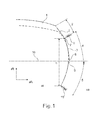
- the Fig.1 shows a cross section through the outer contour of a half-pneumatic vehicle tire.
- the outer contour is shown by the solid line.
- the pneumatic vehicle tire is a Van tire and has a tread 1, a tire shoulder 2 and a side wall 3.
- the outer wall of the shoulder area 2 and the outer contour of the upper side wall area 4 are convexly curved (curved axially outward), the only exception being the forced recess 7 in the area the split line 6.
- the side wall 3 has a protective element 8 against damage by abrasion contacts, which is integrated into the outer contour of the upper side wall portion 4.
- the protective element 8 is arranged approximately in the equator 10 of the tire.
- the lower side wall portion 5 is offset by an axially inwardly projecting step 9 with respect to the contour of the upper side wall portion 4 to axially inside offset and has a likewise only curved continuous convex contour.
- the radially inner end of the step 9, which separates the upper side wall portion 4 from the lower side wall portion 5, is located at 60% of the radial height (h) of the side wall 3 starting from the first split line 6, which shoulder portion 2 is from the upper side wall portion 4 separates.
- the sidewall of the tire is formed by the sidewall shell of a segmented vulcanizing mold and extends from the first split line 6 to the second split line 15 which separates the sidewall from the bead region of the tire.
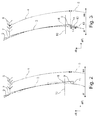
- the Fig.2 shows an enlargement of a section of the outer contour of the tire shoulder 2 and the outer contour of the side wall 3 of Fig.1 , Dotted the outer contour of tires of the prior art is shown with protective rib, wherein in the first split line 6 and in particular in the region of the protective rib, the outer contour of the protective rib of the prior art protrudes axially outwardly from the shoulder and side wall contour.
- the step 9 has an axial width 11 of 1 mm to 4 mm, here of 1.5 mm, so that the contour of the lower side wall region is here offset by 1.5 mm with respect to the contour of the upper side wall region to axially inside (ai).
- the Figure 3 is different from the Fig.2 in that the step 9 is formed in steps from a further half-step 12, wherein the half-step 12 is arranged axially inwardly adjacent to the step 9 and to the lower side wall region 5.
- the axial width 13 of the half-step 12 corresponds approximately to half the axial width 11 of the step 9.
- the radial height of the half-step 14 is 3mm to 10mm, here 5mm, which is about 5.5% of the radial height (h) of the side wall.
Landscapes
- Engineering & Computer Science (AREA)
- Mechanical Engineering (AREA)
- Tires In General (AREA)
- Moulds For Moulding Plastics Or The Like (AREA)
Abstract
Description
- Die Erfindung betrifft einen Fahrzeugluftreifen, insbesondere Van-Reifen, mit einem Laufstreifen, Schulterbereichen und Seitenwänden, wobei - im Reifenquerschnitt betrachtet - eine der Seitenwände im Bereich des Äquators des Fahrzeugluftreifens ein die Seitenwand gegen Scheuerkontakte schützendes, über die Seitenwand umlaufendes Schutzelement aufweist.
- Derartige Fahrzeugluftreifen sind aus dem Stand der Technik bekannt. Das Schutzelement ist üblicherweise eine auf die Seitenwand aufgesetzte, über diese umlaufende und fest mit dieser verbundene Gummirippe. Das Schutzelement steht aus der Seitenwandkontur nach axial außen hervor und ist derart dimensioniert, dass Scheuerkontakte und dadurch hervorrufbare Verletzungen des Reifens abgefangen und verhindert werden können.
- Bei Van-Reifen ist diese umlaufende, auf die Seitenwand aufgesetzte Gummirippe im Bereich des sogenannten "Äquators" angeordnet. Der Äquator des Reifens ist die in axialer Richtung betrachtet breiteste Stelle des Reifens.
- Nachteilig ist jedoch, dass durch dieses, auf die Seitenwand aufgesetzte Schutzelement Probleme bei der Einformung des noch unvulkanisierten Reifens in die Vulkanisierform, beispielsweise in Form von unerwünschten Lufteinschlüssen, entstehen können. Zudem führt das auf die Seitenwand aufgesetzte Schutzelement während des Fahrbetriebes zu einem erhöhten Luftwiderstand des Fahrzeugluftreifens.
- Es ist daher die Aufgabe der Erfindung, einen Fahrzeugluftreifen, insbesondere einen Van-Reifen mit einem Schutzelement im Äquatorbereich des Reifens zur Verfügung zu stellen, der während der Vulkanisation in seiner Einformbarkeit und der während seine Fahrbetriebes aerodynamisch verbessert ist.
- Die Aufgabe wird gelöst, indem -im Reifenquerschnitt betrachtet - die Seitenwand aus einem oberen und einem unteren Seitenwandbereich besteht, dass die äußere Kontur des Schulterbereiches und des oberen Seitenwandbereiches ausschließlich krümmungsstetig konvex ausgebildet ist, dass das Schutzelement in die äußere Kontur des oberen Seitenwandbereiches integriert ist und dass der untere Seitenwandbereich durch eine nach axial innen einspringende Stufe gegenüber der äußeren Kontur des oberen Seitenwandbereiches nach axial innen versetzt angeordnet ist sowie eine ebenfalls ausschließlich krümmungsstetig konvex ausgebildete Kontur aufweist.
- Der erfindungsgemäße Fahrzeugluftreifen zeichnet sich dadurch aus, dass das Schutzelement im oberen Seitenwandbereich in diese Seitenwandkontur integriert ist und dort nicht aus der krümmungsstetigen äußeren Kontur der oberen Seitenwand hervorsteht, also nicht auf die Seitenwand aufgesetzt ist. Ebenso sind die Krümmungen der konvexen Konturen des Schulterbereiches und des oberen Seitenwandbereiches einander angepasst, so dass beide Konturen, die Kontur des Schulterbereiches und die Kontur des oberen Seitenwandbereiches konvex und miteinander fluchtend ohne Kontursprung aerodynamisch günstig sowie für das Einformen des Reifenrohlings während des Vulkanisiervorganges vorteilhaft ausgebildet ist. Die Aerodynamik des Fahrzeugluftreifens während des Fahrbetriebes als auch die Einformung während des Vulkanisiervorganges sind verbessert.
- Vorteilhaft ist es, wenn der Fahrzeugluftreifen mit einer segmentierten Vulkanisierform heizgepresst ist, so dass der Laufstreifen und der Schulterbereich durch radial verfahrbare Formsegmente und jede Seitenwand durch eine an die radial verfahrbaren Formsegmente angrenzende Seitenwandschale geformt ist, so dass der mit dieser Vulkanisierform vulkanisierte Fahrzeugluftreifen im Bereich der Grenzfläche von radial verfahrbaren Formsegmenten zur Seitenwandschale eine (sogenannte) Splitlinie aufweist und wenn der obere Seitenwandbereich (beginnend von dieser Splitlinie) zwischen 50% und 70%, vorzugsweise etwa 60% und der untere Seitenwandbereich zwischen 50% und 30%, vorzugsweise etwa 40% der radialen Höhe der durch die Seitenwandschale geformten Reifenseitenwand einnimmt. Es ist durch das zusätzliche Angebot an Gummimaterial sichergestellt, dass der Reifen vor Beschädigungen durch Scheuerkontakten geschützt ist und somit in seiner Lebensdauer erhöht ist. Im Bereich der Splitlinie kann eine kleine, rein formenbedingte Ausnehmung angeordnet sein, die jedoch aus der Beschreibung der erfindungsgemäßen Kontur ausgenommen sein soll.
- Vorteilhaft ist es, wenn die Stufe treppenartig aus wenigstens einer weiteren Halbstufe gebildet ist, wobei die Halbstufe radial innen an die Stufe und an den unteren Seitenwandbereich angrenzend angeordnet ist und welche eine geringere axiale Breite als die Stufe aufweist. Durch diese treppenartige Anordnung ist die Seitenwand im Bereich der Stufe vorteilhaft versteift. Die Halbstufe weist eine radiale Höhe von 3mm bis 10mm, vorteilhafterweise von 5mm und etwa die halbe axiale Breite der Stufe auf Hierbei kann die Halbstufe über den Umfang des Reifens Durchbrechungen aufweisen, wobei vorzugsweise drei Halbstufen und drei Durchbrechungen angeordnet sind, wobei eine Halbstufe mit einer Durchbrechung regelmäßig mit gleichen Umfangslängen abwechselt. Durch die Durchbrechungen ist die Fläche für mögliche Kennzeichnungen des Reifens vergrößert.
- Das aerodynamische Verhalten des Fahrzeugluftreifens ist weiterhin verbessert, wenn auf der Seitenwand nur vertiefte, in die Reifenseitenwand eingebrachte Kennzeichnungen angeordnet sind. Bisher auf Seitenwänden angeordnete erhabene, aerodynamisch ungünstige Kennzeichnungen sind vermieden.
- Die Splitlinie bezeichnet am Fahrzeugluftreifen -im Reifenquerschnitt betrachtet- die radial verlaufende, gedachte Linie, an der das den Laufstreifen formende Formsegment der Vulkanisierform an die die Seitenwand formende Seitenwandschale der Vulkanisierform angrenzt.
- Weitere Merkmale, Vorteile und Einzelheiten der Erfindung werden anhand der Zeichnungen, die schematische Ausführungsbeispiele darstellen, näher erläutert.
- Es zeigen die:
-
Fig.1 einen Querschnitt durch die äußere Kontur eines hälftigen Fahrzeugluftreifens; -
Fig.2 eine Vergrößerung eines Ausschnitts der Schulterkontur und der Seitenwandkontur derFig.1 ; -
Fig.3 eine weitere Vergrößerung eines Ausschnitts der Schulterkontur und der Seitenwandkontur mit treppenartig ausgestalteter Stufe. - Die
Fig.1 zeigt einen Querschnitt durch die äußere Kontur eines hälftigen Fahrzeugluftreifens. Die äußere Kontur ist mit der durchgezogenen Linie dargestellt. Der Fahrzeugluftreifen ist ein Van-Reifen und weist einen Laufstreifen 1, eine Reifenschulter 2 und eine Seitenwand 3 auf. Die Seitenwand 3 besteht aus einem oberen Seitenwandbereich 4 und einem unteren Seitenwandbereich 5. Die äußere Kontur des Schulterbereiches 2 und die äußere Kontur des oberen Seitenwandbereiches 4 sind krümmungsstetig konvex (nach axial außen gekrümmt) ausgebildet -die einzige Ausnahme ist die zwangsweise Ausnehmung 7 im Bereich der Splitlinie 6. Die Seitenwand 3 weist ein Schutzelement 8 gegen Beschädigungen durch Scheuerkontakte auf, welches in die äußere Kontur des oberen Seitenwandbereiches 4 integriert ist. Das Schutzelement 8 ist etwa im Äquator 10 des Reifens angeordnet. Der untere Seitenwandbereich 5 ist durch eine nach axial innen einspringende Stufe 9 gegenüber der Kontur des oberen Seitenwandbereiches 4 nach axial innen versetzt angeordnet und weist eine ebenfalls ausschließlich krümmungsstetig konvex ausgebildete Kontur auf. Das radial innere Ende der Stufe 9, welches den oberen Seitenwandbereich 4 von den unteren Seitenwandbereich 5 trennt ist, befindet sich auf 60% der radialen Höhe (h) der Seitenwand 3, beginnend von der ersten Splitlinie 6, welche Schulterbereich 2 vom oberen Seitenwandbereich 4 trennt. Die Seitenwand des Reifens ist durch die Seitenwandschale einer segmentierten Vulkanisierform geformt und reicht von der ersten Splitlinie 6 bis zur zweiten Splitlinie 15, welche die Seitenwand von dem Wulstbereich des Reifens trennt. - Die
Fig.2 zeigt eine Vergrößerung eines Ausschnitts der äußeren Kontur der Reifenschulter 2 und der äußeren Kontur der Seitenwand 3 derFig.1 . Punktiert ist die äußere Kontur von Reifen des Standes der Technik mit Schutzrippe dargestellt, wobei bei der ersten Splitlinie 6 als auch insbesondere im Bereich der Schutzrippe die äußere Kontur der Schutzrippe des Standes der Technik nach axial außen aus der Schulter - und Seitenwandkontur herausragt. - Die Stufe 9 weist eine axiale Breite 11 von 1mm bis 4mm, hier von 1,5mm, so dass die Kontur des unteren Seitenwandbereiches hier um 1,5mm gegenüber der Kontur des oberen Seitenwandbereiches nach axial innen (ai) versetzt angeordnet ist.
- Die
Fig.3 unterscheidet sich von derFig.2 darin, dass die Stufe 9 treppenartig aus einer weiteren Halbstufe 12 gebildet ist, wobei die Halbstufe 12 axial innen an die Stufe 9 und an den unteren Seitenwandbereich 5 angrenzend angeordnet ist. Die axiale Breite 13 der Halbstufe 12 entspricht in etwa der halben axialen Breite 11 der Stufe 9. Die radiale Höhe der Halbstufe 14 beträgt 3mm bis 10mm, hier 5mm, was etwa 5,5% der radialen Höhe (h) der Seitenwand. - In den Figuren ist in gestrichelter Linie die neutrale Seitenwandkontur des Reifens ohne zusätzliches Seitenwandgummimaterial dargestellt.
-
- 1
- Laufstreifen
- 2
- Reifenschulter
- 3
- Seitenwand
- 4
- oberer Seitenwandbereich
- 5
- unterer Seitenwandbereich
- 6
- erste Splitlinie
- 7
- Ausnehmung
- 8
- Schutzelement
- 9
- Stufe
- 10
- Äquator
- 11
- axiale Breite der Stufe
- 12
- Halbstufe
- 13
- axiale Breite der Halbstufe
- 14
- radiale Höhe der Halbstufe
- 15
- zweite Splitlinie
- aR
- axiale Richtung
- rR
- radiale Richtung
- ai
- axial innen
- aa
- axial außen
Claims (6)
- Fahrzeugluftreifen, insbesondere Van-Reifen, mit einem Laufstreifen (1), Schulterbereichen (2) und Seitenwänden (3), wobei - im Reifenquerschnitt betrachtet ― eine der Seitenwände (3) im Bereich des Äquators (10) des Fahrzeugluftreifens ein die Seitenwand (3) gegen Scheuerkontakte schützendes, über die Seitenwand umlaufendes Schutzelement (8) aufweist,
dadurch gekennzeichnet, dass ―im Reifenquerschnitt betrachtet ― die Seitenwand (3) aus einem oberen Seitenwandbereich (4) und einem unteren Seitenwandbereich (5) besteht, dass die äußere Kontur des Schulterbereiches (2) und des oberen Seitenwandbereiches (4) ausschließlich krümmungsstetig konvex ausgebildet ist, dass das Schutzelement (8) in die Kontur des oberen Seitenwandbereiches integriert ist und dass der untere Seitenwandbereich (5) durch eine nach axial innen einspringende Stufe (9) gegenüber der Kontur des oberen Seitenwandbereiches (4) nach axial innen versetzt angeordnet ist und eine ebenfalls ausschließlich krümmungsstetig konvex ausgebildete Kontur aufweist. - Fahrzeugluftreifen nach Anspruch 1,
dadurch gekennzeichnet, dass die Stufe (9) eine axiale Breite (11) von 1mm bis 4mm, vorzugsweise von 1,5mm aufweist. - Fahrzeugluftreifen nach Anspruch 1 oder 2,
dadurch gekennzeichnet, dass der Fahrzeugluftreifen mit einer segmentierten Vulkanisierform heizgepresst ist, so dass der Laufstreifen (1) und der Schulterbereich (2) durch radial verfahrbare Formsegmente und jede Seitenwand (3) durch eine an die radial verfahrbaren Formsegmente angrenzende Seitenwandschale geformt ist, so dass der vulkanisierte Fahrzeugluftreifen im Bereich der Grenzfläche von radial verfahrbaren Formsegmenten zur Seitenwandschale eine Splitlinie (6) aufweist und dass der obere Seitenwandbereich (4) zwischen 50% und 70%, vorzugsweise etwa 60% und der untere Seitenwandbereich (5) zwischen 50% und 30%, vorzugsweise etwa 40% der mit der Seitenwandschale geformten Seitenwand (3) einnimmt. - Fahrzeugluftreifen nach einem der Ansprüche 1 bis 3, dadurch gekennzeichnet, dass die Stufe (9) treppenartig aus wenigstens einer weiteren Halbstufe (12) gebildet ist, wobei die Halbstufe (12) radial innen an die Stufe (9) und an den unteren Seitenwandbereich (5) angrenzend angeordnet ist und eine geringere axiale Breite (11) als die Stufe (9) aufweist.
- Fahrzeugluftreifen nach Anspruch 4, dadurch gekennzeichnet, dass die Halbstufe (12) über den Umfang des Reifens Durchbrechungen aufweist, wobei vorzugsweise drei Halbstufen (12) und drei Durchbrechungen, welche regelmäßig einander abwechseln, angeordnet sind.
- Fahrzeugluftreifen nach einem oder mehreren der vorangehenden Ansprüche,
dadurch gekennzeichnet, dass der Fahrzeugluftreifen auf seiner Seitenwand (3) nur vertiefte, in die Seitenwand (3) eingebrachte Kennzeichnungen aufweist.
Applications Claiming Priority (1)
| Application Number | Priority Date | Filing Date | Title |
|---|---|---|---|
| DE201010015845 DE102010015845A1 (de) | 2010-03-08 | 2010-03-08 | Fahrzeugluftreifen |
Publications (3)
| Publication Number | Publication Date |
|---|---|
| EP2368725A2 true EP2368725A2 (de) | 2011-09-28 |
| EP2368725A3 EP2368725A3 (de) | 2011-11-02 |
| EP2368725B1 EP2368725B1 (de) | 2012-11-14 |
Family
ID=44170045
Family Applications (1)
| Application Number | Title | Priority Date | Filing Date |
|---|---|---|---|
| EP20110151477 Active EP2368725B1 (de) | 2010-03-08 | 2011-01-20 | Fahrzeugluftreifen |
Country Status (2)
| Country | Link |
|---|---|
| EP (1) | EP2368725B1 (de) |
| DE (1) | DE102010015845A1 (de) |
Cited By (5)
| Publication number | Priority date | Publication date | Assignee | Title |
|---|---|---|---|---|
| EP2447089A1 (de) * | 2010-10-29 | 2012-05-02 | Mavic S.A.S. | Reifen und Rad für Fahrrad |
| CN103358826A (zh) * | 2012-04-04 | 2013-10-23 | 横滨橡胶株式会社 | 充气轮胎 |
| EP3492253A1 (de) * | 2017-12-01 | 2019-06-05 | Continental Reifen Deutschland GmbH | Fahrzeugluftreifen, vulkanisationswerkzeug zur herstellung eines derartigen fahrzeugluftreifens und verfahren zur herstellung eines fahrzeugluftreifens unter verwendung eines vulkanisationswerkzeuges |
| EP3495129A1 (de) * | 2017-12-05 | 2019-06-12 | Continental Reifen Deutschland GmbH | Fahrzeugluftreifen, vulkanisationswerkzeug zur herstellung eines derartigen fahrzeugluftreifens und verfahren zur herstellung eines fahrzeugluftreifens unter verwendung eines vulkanisationswerkzeuges |
| EP3533639A1 (de) * | 2018-03-02 | 2019-09-04 | Sumitomo Rubber Industries Ltd. | Reifen |
Families Citing this family (3)
| Publication number | Priority date | Publication date | Assignee | Title |
|---|---|---|---|---|
| DE102011051921B4 (de) | 2011-07-19 | 2022-12-29 | Continental Reifen Deutschland Gmbh | Fahrzeugreifen mit einem Laufstreifen |
| DE102012108910A1 (de) | 2012-09-21 | 2014-03-27 | Continental Reifen Deutschland Gmbh | Fahrzeugluftreifen |
| DE102018210577A1 (de) | 2018-06-28 | 2020-01-02 | Continental Reifen Deutschland Gmbh | Fahrzeugluftreifen |
Family Cites Families (6)
| Publication number | Priority date | Publication date | Assignee | Title |
|---|---|---|---|---|
| US2874746A (en) * | 1955-05-16 | 1959-02-24 | Us Rubber Co | Colored sidewall tires |
| US4809757A (en) * | 1985-08-16 | 1989-03-07 | The Firestone Tire & Rubber Company | Curb scuff protection for tire sidewall |
| JP3131795B2 (ja) * | 1992-01-22 | 2001-02-05 | 横浜ゴム株式会社 | 空気入りタイヤ |
| US5599409A (en) * | 1995-07-14 | 1997-02-04 | Bridgestone/Firestone, Inc. | Radial tire/wheel assembly for high brake heat generated service |
| JP2001150910A (ja) * | 1999-11-29 | 2001-06-05 | Bridgestone Corp | 空気入りタイヤ |
| WO2009084634A1 (ja) * | 2007-12-28 | 2009-07-09 | Bridgestone Corporation | 空気入りタイヤ |
-
2010
- 2010-03-08 DE DE201010015845 patent/DE102010015845A1/de not_active Withdrawn
-
2011
- 2011-01-20 EP EP20110151477 patent/EP2368725B1/de active Active
Non-Patent Citations (1)
| Title |
|---|
| None |
Cited By (7)
| Publication number | Priority date | Publication date | Assignee | Title |
|---|---|---|---|---|
| EP2447089A1 (de) * | 2010-10-29 | 2012-05-02 | Mavic S.A.S. | Reifen und Rad für Fahrrad |
| CN103358826A (zh) * | 2012-04-04 | 2013-10-23 | 横滨橡胶株式会社 | 充气轮胎 |
| CN103358826B (zh) * | 2012-04-04 | 2016-01-13 | 横滨橡胶株式会社 | 充气轮胎 |
| EP3492253A1 (de) * | 2017-12-01 | 2019-06-05 | Continental Reifen Deutschland GmbH | Fahrzeugluftreifen, vulkanisationswerkzeug zur herstellung eines derartigen fahrzeugluftreifens und verfahren zur herstellung eines fahrzeugluftreifens unter verwendung eines vulkanisationswerkzeuges |
| EP3495129A1 (de) * | 2017-12-05 | 2019-06-12 | Continental Reifen Deutschland GmbH | Fahrzeugluftreifen, vulkanisationswerkzeug zur herstellung eines derartigen fahrzeugluftreifens und verfahren zur herstellung eines fahrzeugluftreifens unter verwendung eines vulkanisationswerkzeuges |
| EP3533639A1 (de) * | 2018-03-02 | 2019-09-04 | Sumitomo Rubber Industries Ltd. | Reifen |
| US11400761B2 (en) | 2018-03-02 | 2022-08-02 | Sumitomo Rubber Industries, Ltd. | Tire |
Also Published As
| Publication number | Publication date |
|---|---|
| DE102010015845A1 (de) | 2011-09-08 |
| EP2368725A3 (de) | 2011-11-02 |
| EP2368725B1 (de) | 2012-11-14 |
Similar Documents
| Publication | Publication Date | Title |
|---|---|---|
| EP2368725B1 (de) | Fahrzeugluftreifen | |
| EP3083278B1 (de) | Fahrzeugluftreifen | |
| DE69830826T2 (de) | Verbesserte Luftreifenkonstruktion und Verfahren zur Herstellung | |
| DE102010016550A1 (de) | Fahrzeugluftreifen | |
| DE102011001877B4 (de) | Fahrzeugluftreifen | |
| EP3038843B1 (de) | Fahrzeugluftreifen | |
| DE102008028780A1 (de) | Fahrzeugluftreifen mit Felgenschutzrippe | |
| EP2711202B1 (de) | Fahrzeugluftreifen | |
| EP2939855B1 (de) | Fahrzeugluftreifen aufweisend einen Streifen aus einer elektrisch leitfähigen Gummimischung | |
| DE112019005505B4 (de) | Luftreifen | |
| EP3083277B1 (de) | Fahrzeugluftreifen | |
| EP2719524B1 (de) | Vulkanisierform zum vulkansieren von fahrzeugreifen | |
| EP3140132B1 (de) | Fahrzeugluftreifen | |
| EP4015241B1 (de) | Vollreifen und verfahren zur herstellung | |
| EP3395590B1 (de) | Fahrzeugluftreifen | |
| EP3281809B1 (de) | Fahrzeugluftreifen mit selbstdichtenden eigenschaften | |
| EP3321109A1 (de) | Fahrzeugluftreifen | |
| EP4054866B1 (de) | Fahrzeugluftreifen mit felgenschutzrippe | |
| EP2019757B1 (de) | Fahrzeugluftreifen mit gürtelbandage | |
| EP3564046B1 (de) | Fahrzeugluftreifen | |
| DE10036999C2 (de) | Vulkanisiervorrichtung zum Vulkanisieren eines Kautschukartikels sowie Verfahren zum Formen und Vulkanisieren eines Kautschukartikels, insbesondere eines Fahrzeugreifens in einer Vulkanisiereinrichtung | |
| EP1535761B1 (de) | Fahrzeugluftreifen | |
| EP2511308B1 (de) | Fahrzeugluftreifen | |
| EP2048005B1 (de) | Fahrzeugluftreifen | |
| DE102012107606A1 (de) | Selbstdichtender Fahrzeugluftreifen |
Legal Events
| Date | Code | Title | Description |
|---|---|---|---|
| PUAI | Public reference made under article 153(3) epc to a published international application that has entered the european phase |
Free format text: ORIGINAL CODE: 0009012 |
|
| AK | Designated contracting states |
Kind code of ref document: A2 Designated state(s): AL AT BE BG CH CY CZ DE DK EE ES FI FR GB GR HR HU IE IS IT LI LT LU LV MC MK MT NL NO PL PT RO RS SE SI SK SM TR |
|
| AX | Request for extension of the european patent |
Extension state: BA ME |
|
| PUAL | Search report despatched |
Free format text: ORIGINAL CODE: 0009013 |
|
| AK | Designated contracting states |
Kind code of ref document: A3 Designated state(s): AL AT BE BG CH CY CZ DE DK EE ES FI FR GB GR HR HU IE IS IT LI LT LU LV MC MK MT NL NO PL PT RO RS SE SI SK SM TR |
|
| AX | Request for extension of the european patent |
Extension state: BA ME |
|
| RIC1 | Information provided on ipc code assigned before grant |
Ipc: B60C 13/02 20060101AFI20110928BHEP |
|
| 17P | Request for examination filed |
Effective date: 20120502 |
|
| GRAP | Despatch of communication of intention to grant a patent |
Free format text: ORIGINAL CODE: EPIDOSNIGR1 |
|
| GRAS | Grant fee paid |
Free format text: ORIGINAL CODE: EPIDOSNIGR3 |
|
| GRAA | (expected) grant |
Free format text: ORIGINAL CODE: 0009210 |
|
| AK | Designated contracting states |
Kind code of ref document: B1 Designated state(s): AL AT BE BG CH CY CZ DE DK EE ES FI FR GB GR HR HU IE IS IT LI LT LU LV MC MK MT NL NO PL PT RO RS SE SI SK SM TR |
|
| REG | Reference to a national code |
Ref country code: GB Ref legal event code: FG4D Free format text: NOT ENGLISH |
|
| REG | Reference to a national code |
Ref country code: CH Ref legal event code: EP Ref country code: AT Ref legal event code: REF Ref document number: 583763 Country of ref document: AT Kind code of ref document: T Effective date: 20121115 |
|
| REG | Reference to a national code |
Ref country code: IE Ref legal event code: FG4D Free format text: LANGUAGE OF EP DOCUMENT: GERMAN |
|
| REG | Reference to a national code |
Ref country code: DE Ref legal event code: R096 Ref document number: 502011000198 Country of ref document: DE Effective date: 20130110 |
|
| REG | Reference to a national code |
Ref country code: NL Ref legal event code: VDEP Effective date: 20121114 |
|
| REG | Reference to a national code |
Ref country code: LT Ref legal event code: MG4D |
|
| PG25 | Lapsed in a contracting state [announced via postgrant information from national office to epo] |
Ref country code: ES Free format text: LAPSE BECAUSE OF FAILURE TO SUBMIT A TRANSLATION OF THE DESCRIPTION OR TO PAY THE FEE WITHIN THE PRESCRIBED TIME-LIMIT Effective date: 20130225 Ref country code: HR Free format text: LAPSE BECAUSE OF FAILURE TO SUBMIT A TRANSLATION OF THE DESCRIPTION OR TO PAY THE FEE WITHIN THE PRESCRIBED TIME-LIMIT Effective date: 20121114 Ref country code: LT Free format text: LAPSE BECAUSE OF FAILURE TO SUBMIT A TRANSLATION OF THE DESCRIPTION OR TO PAY THE FEE WITHIN THE PRESCRIBED TIME-LIMIT Effective date: 20121114 Ref country code: NO Free format text: LAPSE BECAUSE OF FAILURE TO SUBMIT A TRANSLATION OF THE DESCRIPTION OR TO PAY THE FEE WITHIN THE PRESCRIBED TIME-LIMIT Effective date: 20130214 Ref country code: FI Free format text: LAPSE BECAUSE OF FAILURE TO SUBMIT A TRANSLATION OF THE DESCRIPTION OR TO PAY THE FEE WITHIN THE PRESCRIBED TIME-LIMIT Effective date: 20121114 Ref country code: SE Free format text: LAPSE BECAUSE OF FAILURE TO SUBMIT A TRANSLATION OF THE DESCRIPTION OR TO PAY THE FEE WITHIN THE PRESCRIBED TIME-LIMIT Effective date: 20121114 |
|
| PG25 | Lapsed in a contracting state [announced via postgrant information from national office to epo] |
Ref country code: LV Free format text: LAPSE BECAUSE OF FAILURE TO SUBMIT A TRANSLATION OF THE DESCRIPTION OR TO PAY THE FEE WITHIN THE PRESCRIBED TIME-LIMIT Effective date: 20121114 Ref country code: PL Free format text: LAPSE BECAUSE OF FAILURE TO SUBMIT A TRANSLATION OF THE DESCRIPTION OR TO PAY THE FEE WITHIN THE PRESCRIBED TIME-LIMIT Effective date: 20121114 Ref country code: GR Free format text: LAPSE BECAUSE OF FAILURE TO SUBMIT A TRANSLATION OF THE DESCRIPTION OR TO PAY THE FEE WITHIN THE PRESCRIBED TIME-LIMIT Effective date: 20130215 Ref country code: PT Free format text: LAPSE BECAUSE OF FAILURE TO SUBMIT A TRANSLATION OF THE DESCRIPTION OR TO PAY THE FEE WITHIN THE PRESCRIBED TIME-LIMIT Effective date: 20130314 Ref country code: SI Free format text: LAPSE BECAUSE OF FAILURE TO SUBMIT A TRANSLATION OF THE DESCRIPTION OR TO PAY THE FEE WITHIN THE PRESCRIBED TIME-LIMIT Effective date: 20121114 |
|
| BERE | Be: lapsed |
Owner name: CONTINENTAL REIFEN DEUTSCHLAND G.M.B.H. Effective date: 20130131 |
|
| PG25 | Lapsed in a contracting state [announced via postgrant information from national office to epo] |
Ref country code: SK Free format text: LAPSE BECAUSE OF FAILURE TO SUBMIT A TRANSLATION OF THE DESCRIPTION OR TO PAY THE FEE WITHIN THE PRESCRIBED TIME-LIMIT Effective date: 20121114 Ref country code: EE Free format text: LAPSE BECAUSE OF FAILURE TO SUBMIT A TRANSLATION OF THE DESCRIPTION OR TO PAY THE FEE WITHIN THE PRESCRIBED TIME-LIMIT Effective date: 20121114 Ref country code: BG Free format text: LAPSE BECAUSE OF FAILURE TO SUBMIT A TRANSLATION OF THE DESCRIPTION OR TO PAY THE FEE WITHIN THE PRESCRIBED TIME-LIMIT Effective date: 20130214 Ref country code: RS Free format text: LAPSE BECAUSE OF FAILURE TO SUBMIT A TRANSLATION OF THE DESCRIPTION OR TO PAY THE FEE WITHIN THE PRESCRIBED TIME-LIMIT Effective date: 20121114 Ref country code: CZ Free format text: LAPSE BECAUSE OF FAILURE TO SUBMIT A TRANSLATION OF THE DESCRIPTION OR TO PAY THE FEE WITHIN THE PRESCRIBED TIME-LIMIT Effective date: 20121114 Ref country code: DK Free format text: LAPSE BECAUSE OF FAILURE TO SUBMIT A TRANSLATION OF THE DESCRIPTION OR TO PAY THE FEE WITHIN THE PRESCRIBED TIME-LIMIT Effective date: 20121114 |
|
| PG25 | Lapsed in a contracting state [announced via postgrant information from national office to epo] |
Ref country code: RO Free format text: LAPSE BECAUSE OF FAILURE TO SUBMIT A TRANSLATION OF THE DESCRIPTION OR TO PAY THE FEE WITHIN THE PRESCRIBED TIME-LIMIT Effective date: 20121114 Ref country code: NL Free format text: LAPSE BECAUSE OF FAILURE TO SUBMIT A TRANSLATION OF THE DESCRIPTION OR TO PAY THE FEE WITHIN THE PRESCRIBED TIME-LIMIT Effective date: 20121114 Ref country code: IT Free format text: LAPSE BECAUSE OF FAILURE TO SUBMIT A TRANSLATION OF THE DESCRIPTION OR TO PAY THE FEE WITHIN THE PRESCRIBED TIME-LIMIT Effective date: 20121114 Ref country code: MC Free format text: LAPSE BECAUSE OF NON-PAYMENT OF DUE FEES Effective date: 20130131 |
|
| PLBE | No opposition filed within time limit |
Free format text: ORIGINAL CODE: 0009261 |
|
| STAA | Information on the status of an ep patent application or granted ep patent |
Free format text: STATUS: NO OPPOSITION FILED WITHIN TIME LIMIT |
|
| 26N | No opposition filed |
Effective date: 20130815 |
|
| REG | Reference to a national code |
Ref country code: IE Ref legal event code: MM4A |
|
| PG25 | Lapsed in a contracting state [announced via postgrant information from national office to epo] |
Ref country code: BE Free format text: LAPSE BECAUSE OF NON-PAYMENT OF DUE FEES Effective date: 20130131 |
|
| PG25 | Lapsed in a contracting state [announced via postgrant information from national office to epo] |
Ref country code: CY Free format text: LAPSE BECAUSE OF FAILURE TO SUBMIT A TRANSLATION OF THE DESCRIPTION OR TO PAY THE FEE WITHIN THE PRESCRIBED TIME-LIMIT Effective date: 20121114 |
|
| REG | Reference to a national code |
Ref country code: DE Ref legal event code: R097 Ref document number: 502011000198 Country of ref document: DE Effective date: 20130815 |
|
| PG25 | Lapsed in a contracting state [announced via postgrant information from national office to epo] |
Ref country code: IE Free format text: LAPSE BECAUSE OF NON-PAYMENT OF DUE FEES Effective date: 20130120 Ref country code: AL Free format text: LAPSE BECAUSE OF FAILURE TO SUBMIT A TRANSLATION OF THE DESCRIPTION OR TO PAY THE FEE WITHIN THE PRESCRIBED TIME-LIMIT Effective date: 20121114 |
|
| PG25 | Lapsed in a contracting state [announced via postgrant information from national office to epo] |
Ref country code: MT Free format text: LAPSE BECAUSE OF FAILURE TO SUBMIT A TRANSLATION OF THE DESCRIPTION OR TO PAY THE FEE WITHIN THE PRESCRIBED TIME-LIMIT Effective date: 20121114 |
|
| REG | Reference to a national code |
Ref country code: CH Ref legal event code: PL |
|
| PG25 | Lapsed in a contracting state [announced via postgrant information from national office to epo] |
Ref country code: LI Free format text: LAPSE BECAUSE OF NON-PAYMENT OF DUE FEES Effective date: 20140131 Ref country code: CH Free format text: LAPSE BECAUSE OF NON-PAYMENT OF DUE FEES Effective date: 20140131 |
|
| PG25 | Lapsed in a contracting state [announced via postgrant information from national office to epo] |
Ref country code: SM Free format text: LAPSE BECAUSE OF FAILURE TO SUBMIT A TRANSLATION OF THE DESCRIPTION OR TO PAY THE FEE WITHIN THE PRESCRIBED TIME-LIMIT Effective date: 20121114 |
|
| PG25 | Lapsed in a contracting state [announced via postgrant information from national office to epo] |
Ref country code: TR Free format text: LAPSE BECAUSE OF FAILURE TO SUBMIT A TRANSLATION OF THE DESCRIPTION OR TO PAY THE FEE WITHIN THE PRESCRIBED TIME-LIMIT Effective date: 20121114 |
|
| PG25 | Lapsed in a contracting state [announced via postgrant information from national office to epo] |
Ref country code: LU Free format text: LAPSE BECAUSE OF NON-PAYMENT OF DUE FEES Effective date: 20130120 Ref country code: HU Free format text: LAPSE BECAUSE OF FAILURE TO SUBMIT A TRANSLATION OF THE DESCRIPTION OR TO PAY THE FEE WITHIN THE PRESCRIBED TIME-LIMIT; INVALID AB INITIO Effective date: 20110120 Ref country code: MK Free format text: LAPSE BECAUSE OF FAILURE TO SUBMIT A TRANSLATION OF THE DESCRIPTION OR TO PAY THE FEE WITHIN THE PRESCRIBED TIME-LIMIT Effective date: 20121114 |
|
| REG | Reference to a national code |
Ref country code: FR Ref legal event code: PLFP Year of fee payment: 6 |
|
| PG25 | Lapsed in a contracting state [announced via postgrant information from national office to epo] |
Ref country code: IS Free format text: LAPSE BECAUSE OF FAILURE TO SUBMIT A TRANSLATION OF THE DESCRIPTION OR TO PAY THE FEE WITHIN THE PRESCRIBED TIME-LIMIT Effective date: 20121114 |
|
| REG | Reference to a national code |
Ref country code: FR Ref legal event code: PLFP Year of fee payment: 7 |
|
| REG | Reference to a national code |
Ref country code: AT Ref legal event code: MM01 Ref document number: 583763 Country of ref document: AT Kind code of ref document: T Effective date: 20160120 |
|
| PG25 | Lapsed in a contracting state [announced via postgrant information from national office to epo] |
Ref country code: AT Free format text: LAPSE BECAUSE OF NON-PAYMENT OF DUE FEES Effective date: 20160120 |
|
| REG | Reference to a national code |
Ref country code: FR Ref legal event code: PLFP Year of fee payment: 8 |
|
| REG | Reference to a national code |
Ref country code: DE Ref legal event code: R081 Ref document number: 502011000198 Country of ref document: DE Owner name: CONTINENTAL REIFEN DEUTSCHLAND GMBH, DE Free format text: FORMER OWNER: CONTINENTAL REIFEN DEUTSCHLAND GMBH, 30165 HANNOVER, DE |
|
| PGFP | Annual fee paid to national office [announced via postgrant information from national office to epo] |
Ref country code: GB Payment date: 20240119 Year of fee payment: 14 |
|
| GBPC | Gb: european patent ceased through non-payment of renewal fee |
Effective date: 20250120 |
|
| PG25 | Lapsed in a contracting state [announced via postgrant information from national office to epo] |
Ref country code: GB Free format text: LAPSE BECAUSE OF NON-PAYMENT OF DUE FEES Effective date: 20250120 |
|
| PGFP | Annual fee paid to national office [announced via postgrant information from national office to epo] |
Ref country code: DE Payment date: 20260131 Year of fee payment: 16 |
|
| PGFP | Annual fee paid to national office [announced via postgrant information from national office to epo] |
Ref country code: FR Payment date: 20260123 Year of fee payment: 16 |