EP2368738A2 - Verfahren, Vorrrichtung und beweglicher Applikationskopf zur Montage einer Dichtung an einer KFZ-Karosserie oder einer Applikationsplatte - Google Patents
Verfahren, Vorrrichtung und beweglicher Applikationskopf zur Montage einer Dichtung an einer KFZ-Karosserie oder einer Applikationsplatte Download PDFInfo
- Publication number
- EP2368738A2 EP2368738A2 EP11001355A EP11001355A EP2368738A2 EP 2368738 A2 EP2368738 A2 EP 2368738A2 EP 11001355 A EP11001355 A EP 11001355A EP 11001355 A EP11001355 A EP 11001355A EP 2368738 A2 EP2368738 A2 EP 2368738A2
- Authority
- EP
- European Patent Office
- Prior art keywords
- seal
- application head
- application
- temporary storage
- rollers
- Prior art date
- Legal status (The legal status is an assumption and is not a legal conclusion. Google has not performed a legal analysis and makes no representation as to the accuracy of the status listed.)
- Granted
Links
Images



Classifications
-
- B—PERFORMING OPERATIONS; TRANSPORTING
- B23—MACHINE TOOLS; METAL-WORKING NOT OTHERWISE PROVIDED FOR
- B23P—METAL-WORKING NOT OTHERWISE PROVIDED FOR; COMBINED OPERATIONS; UNIVERSAL MACHINE TOOLS
- B23P19/00—Machines for simply fitting together or separating metal parts or objects, or metal and non-metal parts, whether or not involving some deformation; Tools or devices therefor so far as not provided for in other classes
- B23P19/04—Machines for simply fitting together or separating metal parts or objects, or metal and non-metal parts, whether or not involving some deformation; Tools or devices therefor so far as not provided for in other classes for assembling or disassembling parts
- B23P19/047—Machines for simply fitting together or separating metal parts or objects, or metal and non-metal parts, whether or not involving some deformation; Tools or devices therefor so far as not provided for in other classes for assembling or disassembling parts for flexible profiles, e.g. sealing or decorating strips in grooves or on other profiles by devices moving along the flexible profile
-
- B—PERFORMING OPERATIONS; TRANSPORTING
- B60—VEHICLES IN GENERAL
- B60J—WINDOWS, WINDSCREENS, NON-FIXED ROOFS, DOORS, OR SIMILAR DEVICES FOR VEHICLES; REMOVABLE EXTERNAL PROTECTIVE COVERINGS SPECIALLY ADAPTED FOR VEHICLES
- B60J10/00—Sealing arrangements
- B60J10/45—Assembling sealing arrangements with vehicle parts
Definitions
- the invention relates to a method, a device and a movable application head for attaching a completely or partially circumferential seal on a vehicle body, a vehicle part or an application plate for subsequent attachment preferably to a vehicle door or other vehicle openings or attachments according to claims 1, 4 and 9 ,
- a method of attaching a gasket to a vehicle door in which a present on a roll as an endless profile seal is withdrawn from the roll and rolled with an adhesive surface along an intended for attachment line on a surface of the vehicle door circumferentially.
- a device comprising a pressure roller over which the seal is guided, and guide means for guiding the seal prior to application, wherein the device for the circumferential attachment of the seal to the vehicle door about an axis is pivotable through 360 °.
- a motor vehicle wherein the application takes place in two stages.
- a seal cut to length from an endless sealing band is placed on retaining strips of an application plate moved past the rolling head with a stationary rolling head.
- the Application plate with the attached gasket pressed against the door opening or the sealing surface of the door itself.
- the circumference of the application plate is guided along the stationary curling head.
- the invention is based on the object to propose a method, a device and a movable application head for attaching a peripheral seal on a vehicle body, a vehicle part or an application plate, which avoided problems in the supply of the seal to the guide rollers and / or the pressure roller and the application head can be guided along the vehicle body, the vehicle part or the application plate without any obstruction.
- the inventive method provides that the seal is preferably withdrawn as an endless profile from a supply roll and wound with at least one turn on a temporary storage role, which is fixed or rotatable connected to the application head and that the temporary storage roll together with the application head for attaching the seal with the help a handling device or a robot along a line provided for the attachment of the seal is moved.
- a temporary storage role which is fixed or rotatable connected to the application head and that the temporary storage roll together with the application head for attaching the seal with the help a handling device or a robot along a line provided for the attachment of the seal is moved.
- at least as much seal should be storable on the intermediate storage roll as is required for the attachment of a seal, for example on the circumference of a door.
- the seal While the circulation movement, the seal from the temporary storage roll, preferably supplied via driven guide rollers to the application head and rolled from there via guide means and / or preferably by opposite guide rollers and with the aid of a pinch roller on the intended adhesive surface of the vehicle body or the vehicle part.
- the seal can be rolled up or attached to retaining strips on an application plate.
- the temporary storage reel is rotated relative to the application head, the gasket optionally being additionally wound or unwound as needed.
- the seal can also be moved on rotatable rollers on the circumference of the temporary storage roller.
- the device according to the invention for applying a seal is characterized by an application head which is rotatably or pivotally mounted on a robot arm or other handling device and has one or more intermediate storage rollers or rollers rotatably or fixedly mounted on the application head for opening and / or closing Unwinding one or more turns of the seal, wherein preferably the application head and the buffer roll are rotatable together by about 360 degrees or more relative to the robot arm or the handling device.
- Caching and / or application head according to the invention are always rotated or pivoted so that entanglement and jamming about the robot axes is avoided during the transfer from the feed to the application head or to the pressure roller.
- the seal can always be kept tight to the required extent despite the changed distance between the feed and the temporary storage role.
- the temporary storage roller can be fixedly arranged on the application head or moved with or without drive in both directions or exert the required tension on the seal with the aid of spring elements.
- the supply of the seal to the pressure roller or corresponding pressing devices is by preferably driven and opposite guide rollers or pulling means, e.g. Timing belt, achieved on corresponding rollers, wherein the guide rollers exert an adjustable contact pressure on the seal.
- This defined and adjustable contact pressure can be carried out in particular by means of a pneumatically or hydraulically controlled pressure membrane which acts on at least one of the guide rollers, or by traction means on rollers.
- the buffer roller has circumferentially distributed on the outer diameter conical, spherical or cylindrical rollers running, on which the seal rests when rolling up. By the conical rollers, the rolling of the seal begins on one side of the temporary storage role. As a result, the position and the leadership of the seal are well defined.
- the movable application head according to the invention for circulating feed and attachment of a seal along a line provided for attachment according to the invention consists of a fixed or rotatable intermediate storage roller attached to the application head, the roller having a smooth cylindrical surface or circumferentially arranged rotatable rollers.
- at least one pressure roller and / or corresponding pressing devices for the seal and drivable guide rollers for forwarding the seal from the intermediate storage roller to the pressure roller are present on the application head.
- sensors and position monitoring devices may be provided in this way for monitoring the speed and position of the seal. These position monitoring devices can be arranged in transport directions of the seal between two driven guide rollers or directly in front of the pressure roller.
- a guide plate can be attached laterally on the application head or else on the intermediate storage roller, on which supply lines of the robot or the handling device may rest or be guided separately from the seal.
- FIG. 1 the procedure for attaching the seal 1 to the retaining strips 23 of an application plate 7 is shown in principle.
- the seal 1 is withdrawn from a stationary supply roll 2 and supplied via deflection rollers 3 and optionally also conveyor rollers 4 of an optional storage system 5 the application system 6 and applied from there via guide rollers 8 and a pinch roller 9 on the periphery of the application plate (7) arranged holding strips 23 , Suitable retaining strips are eg in the EP 0849106 B1 described.
- the seal 1 After circumferential attachment of the seal 1 on the in FIG. 1 along the dashed line arranged retaining strips 23, the seal 1 is cut to size.
- the two sealing ends can be known per se Way dull connected.
- the seal 1 can be brought by means of the application plate 7 in position on the adhesive surfaces of the vehicle door and then glued after returning the expansion with pressure elements, not shown.
- the transport direction of the seal 1 is in the FIGS. 1 to 5 each marked with an arrow.
- the seal 1 is supplied from the temporary storage roller 10 by means of the guide roller 27 having the drive 26 and the pressing rollers 28 to the other guide rollers 8, 11 and 12.
- sensors and devices for position monitoring 29 are provided in front of the guide rollers 8 and possibly also in front of the pinch rollers 9. With the two opposite guide rollers 11, 12, the seal 1 is selectively fed to the pinch roller 9.
- the two guide rollers 11 and 12 exert a defined and optionally adjustable contact pressure on the seal 1, wherein the contact pressure is carried out by means of a pneumatically or hydraulically controlled pressure diaphragm.
- a connecting element 17 is screwed, which in turn is connected by screws or other fasteners to the storage drum 15.
- FIGS. 4 and 5 After the perspective representations of FIGS. 4 and 5 is on the side facing away from the connecting element 17 of the storage drum 15 in addition a guide plate 16, for example, for robot supply lines or other lines releasably connected.
- the buffer roller 10 is slidably guided with its axis of rotation 22 on the storage drum 15 and with respect to the connecting element 17.
- the sliding surfaces 21 are in particular made FIG. 8 seen.
- the conical outer jacket 25 ensures that the winding of the seal 1 on the intermediate storage roll 10 begins at the side where the conical outer jacket 25 or the entire intermediate storage roll 10 has the smallest diameter.
- the storage drum 15 is connected via the connecting plate 20 to a robot arm, not shown, or other handling device, with the robot arm or the handling device, the entire application head 14 (see FIGS. 2 and 3 ) each additionally rotated or swung.
- the application head 14 with the temporary storage roll 10 can also be moved along the periphery directly on the adhesive surface of a motor vehicle door or door opening or other opening of the motor vehicle (eg at the edge of a sunroof opening).
- a peeling off of the protective strip is required.
Landscapes
- Engineering & Computer Science (AREA)
- Mechanical Engineering (AREA)
- Automobile Manufacture Line, Endless Track Vehicle, Trailer (AREA)
Abstract
Description
- Die Erfindung betrifft ein Verfahren, eine Vorrichtung und einen beweglichen Applikationskopf zum Anbringen einer ganz oder teilweise umlaufenden Dichtung an einer Fahrzeugkarosserie, einem Fahrzeugteil oder einer Applikationsplatte zur anschließenden Anbringung vorzugsweise an einer Fahrzeugtür oder an anderen Fahrzeugöffnungen oder Anbauteilen nach den Ansprüchen 1, 4 und 9.
- Aus der
DE 101 38 781 A1 ist ein Verfahren zur Anbringung einer Dichtung an einer Fahrzeugtür bekannt, bei dem eine auf einer Rolle als Endlosprofil vorliegende Dichtung von der Rolle abgezogen und mit einer Klebefläche entlang einer für die Anbringung vorgesehenen Linie auf eine Fläche der Fahrzeugtür umlaufend aufgerollt wird. Zur Durchführung dient dabei eine Vorrichtung, umfassend eine Andruckrolle, über die die Dichtung geführt ist, sowie Führungsmittel zur Führung der Dichtung vor der Aufbringung, wobei die Vorrichtung für die umlaufende Anbringung der Dichtung an der Fahrzeugtür um eine Achse um 360° schwenkbar ist. Über die Art der Führung der Dichtung von der Rolle zur und an der Applikationsvorrichtung ist dieser Schrift nichts zu entnehmen. Bei der Zuführung der Dichtung von einer stationären Vorratsrolle zu dem umlaufend zu bewegenden Applikationskopf kann es dazu kommen, dass sich die Dichtung, z.B. um die Achsen des Roboterarmes verwickelt und verklemmt. Außerdem kann es auf dem relativ langen Wege von der Vorratsrolle zum Applikationskopf zu Längenveränderungen der Dichtung kommen. - In der
DE 10 2006 003 095 B3 ist ein Verfahren und eine Anlage zum Applizieren einer umlaufenden Dichtung an einem Verschlussteil, insbesondere einer Tür, eines Kraftfahrzeuges beschrieben, wobei das Applizieren in zwei Stufen erfolgt. In einer ersten Stufe wird mit einem stationären Anrollkopf eine von einem Endlosdichtungsband abgelängte Dichtung auf am Anrollkopf vorbeibewegte Halteleisten einer Applikationsplatte gesteckt. In einer zweiten Stufe wird die Applikationsplatte mit der aufgesteckten Dichtung an die Türöffnung oder die Dichtungsfläche der Tür selbst angedrückt. Zum Anbringen der Dichtung an der Applikationsplatte wird der Umfang der Applikationsplatte an dem stationären Anrollkopf entlang geführt. - Auch aus der
EP 2067645 A2 ist es bekannt, eine Applikationseinheit stationär auszubilden und dann die Fahrzeugtür an der stationären Andruckrolle mit Hilfe eines Roboterarmes entlang der für die Anbringung der Dichtung vorgesehenen Linie zu bewegen. Um Geschwindigkeitsschwankungen bei der Zuführung der Dichtung zu beherrschen, wird die Relativgeschwindigkeit zwischen Dichtung und Applikationseinheit unmittelbar an der Stelle der Verklebung erfasst. - Der Erfindung liegt die Aufgabe zu Grunde, ein Verfahren, eine Vorrichtung und einen beweglichen Applikationskopf zum Anbringen einer umlaufenden Dichtung an einer Fahrzeugkarosserie, einem Fahrzeugteil oder einer Applikationsplatte vorzuschlagen, bei dem Probleme bei der Zuführung der Dichtung zu den Führungsrollen und/oder der Andruckrolle vermieden und der Applikationskopf ungehindert umlaufend an der Kraftfahrzeugkarosserie, dem Fahrzeugteil oder der Applikationsplatte entlanggeführt werden kann.
- Zur Lösung dieser Aufgabe ist ein Verfahren gemäß Anspruch 1, eine Vorrichtung gemäß Anspruch 4 und ein beweglicher Applikationskopf gemäß Anspruch 9 vorgesehen. Die Unteransprüche 2 und 3, 5 bis 8 sowie 10 enthalten sinnvolle ergänzende Verfahrensvorschläge bzw. Vorrichtungsmerkmale.
- Das erfindungsgemäße Verfahren sieht vor, dass die Dichtung vorzugsweise als Endlosprofil von einer Vorratsrolle abgezogen und mit mindestens einer Windung auf eine Zwischenspeicherrolle aufgewickelt wird, die fest oder drehbar mit dem Applikationskopf verbunden ist und dass die Zwischenspeicherrolle gemeinsam mit dem Applikationskopf zum Anbringen der Dichtung mit Hilfe einer Handhabungsvorrichtung oder eines Roboters entlang einer für die Anbringung der Dichtung vorgesehenen Linie bewegt wird. Üblicherweise sollte mindestens so viel Dichtung auf der Zwischenspeicherrolle speicherbar sein wie für die Anbringung einer Dichtung, z.B. am Umfang einer Tür erforderlich ist. Während der Umlaufbewegung wird die Dichtung von der Zwischenspeicherrolle, vorzugsweise über angetriebene Führungsrollen dem Applikationskopf zugeführt und von dort über Führungsmittel und/oder vorzugsweise durch gegenüberliegende Führungsrollen und mit Hilfe einer Andruckrolle auf die vorgesehene Klebefläche der Fahrzeugkarosserie oder des Fahrzeugteiles aufgerollt. Als Besonderheit kann die Dichtung auf Halteleisten an einer Applikationsplatte aufgerollt oder aufgesteckt werden. Gleichzeitig wird die Zwischenspeicherrolle relativ zum Applikationskopf gedreht, wobei die Dichtung gegebenenfalls bedarfsabhängig zusätzlich auf- oder abgewickelt wird. Alternativ oder zusätzlich zur Drehung der Zwischenspeicherrolle kann die Dichtung auch auf drehbaren Rollen am Umfang der Zwischenspeicherrolle bewegt werden.
- Die erfindungsgemäße Vorrichtung zum Anbringen einer Dichtung, vorzugsweise zur Durchführung des Verfahrens ist gekennzeichnet durch einen an einem Roboterarm oder einer sonstigen Handhabungseinrichtung dreh- oder schwenkbar befestigten Applikationskopf mit einer oder mehreren drehbar oder fest an dem Applikationskopf befestigten Zwischenspeicherrolle/en zum Auf- und/oder Abrollen von ein oder mehreren Windungen der Dichtung, wobei vorzugsweise Applikationskopf und Zwischenspeicherrolle gemeinsam um ca. 360 Grad oder mehr gegenüber dem Roboterarm oder der Handhabungseinrichtung drehbar sind. Zwischenspeicher und/oder Applikationskopf werden erfindungsgemäß immer so gedreht bzw. geschwenkt, dass bei der Übergabe von der Zuführung zum Applikationskopf bzw. zur Andruckrolle ein Verwickeln und Verklemmen um die Roboterachsen vermieden wird. Da sich der Abstand zwischen dem vorzugsweise stationär angeordneten Zuführungs- und/oder Speichersystem während der Umlaufbewegung laufend verändert, werden auf der Zwischenspeicherrolle ausreichende Windungen der Dichtung aufgewickelt und auch entsprechend wieder abgewickelt. Bei einer beispielsweise konstanten Zuführgeschwindigkeit der Dichtung zur Zwischenspeicherrolle kann trotz des veränderten Abstandes zwischen der Zuführung und der Zwischenspeicherrolle die Dichtung immer in erforderlichem Maße stramm gehalten werden. Die Zwischenspeicherrolle kann fest an dem Applikationskopf angeordnet sein oder mit oder ohne Antrieb in beiden Richtungen bewegt werden oder mit Hilfe von Federelementen die erforderliche Zugspannung auf die Dichtung ausüben.
- Die Zuführung der Dichtung zur Andruckrolle oder entsprechenden Andrückvorrichtungen wird durch vorzugsweise angetriebene und gegenüberliegende Führungsrollen oder über Zugmittel, z.B. Zahnriemen, auf entsprechenden Rollen erreicht, wobei die Führungsrollen einen einstellbaren Anpressdruck auf die Dichtung ausüben. Dieser definierte und einstellbare Anpressdruck kann insbesondere mit Hilfe einer pneumatisch oder hydraulisch gesteuerten Druckmembrane, die auf mindestens eine der Führungsrollen wirkt, oder durch Zugmittel auf Rollen ausgeführt werden. Die Zwischenspeicherrolle besitzt am Umfang verteilt am Außendurchmesser konisch, ballig oder zylindrisch ausgeführte Rollen, auf denen die Dichtung beim Aufrollen aufliegt. Durch die konischen Rollen beginnt das Aufrollen der Dichtung jeweils an einer Seite der Zwischenspeicherrolle. Auch hierdurch sind die Lage und die Führung der Dichtung genau definiert.
- Der erfindungsgemäße bewegliche Applikationskopf zur umlaufenden Zuführung und Anbringung einer Dichtung entlang einer für die Anbringung vorgesehenen Linie besteht erfindungsgemäß aus einer fest- oder drehbaren am Applikationskopf befestigten Zwischenspeicherrolle, wobei die Rolle eine glatte zylindrische Oberfläche oder am Umfang angeordnete drehbare Rollen besitzen kann. Außerdem sind am Applikationskopf mindestens eine Andruckrolle und/oder entsprechende Andrückvorrichtungen für die Dichtung und antreibbare Führungsrollen zur Weiterleitung der Dichtung von der Zwischenspeicherrolle zur Andruckrolle vorhanden. Zusätzlich können auf diesem Wege zur Überwachung der Geschwindigkeit und der Position der Dichtung Sensoren und Positionsüberwachungseinrichtungen vorgesehen sein. Diese Positionsüberwachungseinrichtungen können in Transportrichtungen der Dichtung zwischen zwei angetriebenen Führungsrollen oder unmittelbar vor der Andruckrolle angeordnet sein.
- Außerdem kann am Applikationskopf oder auch an der Zwischenspeicherrolle seitlich ein Führungsblech befestigt sein, auf dem getrennt von der Dichtung eventuell Versorgungsleitungen des Roboters oder der Handhabungseinrichtung aufliegen oder geführt werden.
- Die Erfindung wird anhand der beigefügten
Figuren 1 bis 8 beispielsweise näher erläutert. - Es zeigen:
- Figur 1
- eine schematische Gesamtansicht einer Gesamtanlage zur Durchführung des erfindungsgemäßen Verfahrens,
- Figur 2
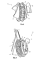
- eine perspektivische Darstellung von Zwischenspeicher 13 und Applikationskopf 14,
- Figur 3
- eine Seitenansicht zu
Figur 2 , - Figur 4
- eine perspektivische Ansicht des Zwischenspeichers 13,
- Figur 5
- eine weitere perspektivische Ansicht des Zwischenspeichers 13,
- Figur 6
- eine Seitenansicht des Zwischenspeichers 13,
- Figur 7
- einen waagerechten Schnitt durch den Zwischenspeicher 13 nach
Figur 6 und - Figur 8
- eine vergrößerte Schnittdarstellung der Zwischenspeicherrolle 10.
- In
Figur 1 ist der Verfahrensablauf zur Anbringung der Dichtung 1 an den Halteleisten 23 einer Applikationsplatte 7 prinzipiell dargestellt. Die Dichtung 1 wird von einer stationären Vorratsrolle 2 abgezogen und über Umlenkrollen 3 und gegebenenfalls auch Förderrollen 4 eines optionalen Speichersystems 5 dem Applikationssystem 6 zugeführt und von dort über Führungsrollen 8 und eine Andruckrolle 9 auf die am Umfang der Applikationsplatte (7) angeordneten Halteleisten 23 aufgebracht. Geeignete Halteleisten sind z.B. in derEP 0849106 B1 beschrieben. Nach umlaufender Befestigung der Dichtung 1 auf den inFigur 1 entlang der gestrichelten Linie angeordneten Halteleisten 23 wird die Dichtung 1 auf Maß abgeschnitten. Die beiden Dichtungsenden können in an sich bekannter Weise stumpf miteinander verbunden werden. Nach definierter Aufweitung der Dichtung durch Bewegung der einzelnen Halteleisten 23 nach außen kann die Dichtung 1 mit Hilfe der Applikationsplatte 7 in Position über den Klebeflächen der Kraftfahrzeugtür gebracht und anschließend nach Rückführung der Aufweitung mit nicht dargestellten Andrückelementen angeklebt werden. - Zum Applikationssystem 6 gehört nach
Figuren 2 und 3 einerseits der eigentliche Applikationskopf 14 und andererseits der Zwischenspeicher 13. An einer Tragplatte 18 sind dabei die soweit erforderlichen antreibbaren Führungsrollen 8, 11, 12 und 27 für die Dichtung 1 befestigt. Die Transportrichtung der Dichtung 1 ist in denFiguren 1 bis 5 jeweils mit einem Pfeil gekennzeichnet. Die Dichtung 1 wird von der Zwischenspeicherrolle 10 mit Hilfe der Führungsrolle 27, die den Antrieb 26 besitzt und den Anpressrollen 28 den weiteren Führungsrollen 8, 11 und 12 zugeführt. Zur Überwachung der Geschwindigkeit und der Position der Dichtung 1 sind Sensoren und Einrichtungen zur Positionsüberwachung 29 vor den Führungsrollen 8 und gegebenenfalls auch vor den Andruckrollen 9 vorgesehen. Mit den beiden gegenüberliegenden Führungsrollen 11, 12 wird die Dichtung 1 gezielt der Andruckrolle 9 zugeführt. Die beiden Führungsrollen 11 und 12 üben dabei einen definierten und gegebenenfalls einstellbaren Anpressdruck auf die Dichtung 1 aus, wobei der Anpressdruck mit Hilfe einer pneumatisch oder hydraulisch gesteuerten Druckmembrane ausgeführt wird. Auf der den Führungsrollen 8, 11 und 12 abgewandten Seite ist an der Tragplatte 18 ein Verbindungselement 17 angeschraubt, das wiederum durch Schrauben oder sonstige Befestigungselemente mit der Speichertrommel 15 verbunden ist. - Nach den perspektivischen Darstellungen der
Figuren 4 und 5 ist auf der dem Verbindungselement 17 abgewandten Seite der Speichertrommel 15 zusätzlich ein Führungsblech 16 z.B. für Roboterversorgungsleitungen oder sonstige Leitungen lösbar verbunden. - Gemäß
Figuren 6 bis 8 ist die Zwischenspeicherrolle 10 mit ihrer Drehachse 22 gleitend auf der Speichertrommel 15 und gegenüber dem Verbindungselement 17 geführt. Die Gleitflächen 21 sind insbesondere ausFigur 8 ersichtlich. Dort ist auch zu sehen, dass die Zwischenspeicherrolle 10 aus zwei seitlichen Führungsringen 24 und diese verbindenden Rollen 19 besteht, wobei die Rollen 19 jeweils einen konischen Außenmantel 25 besitzen und in den Führungsringen 24 drehbar gelagert sind. Durch den konischen Außenmantel 25 wird gewährleistet, dass das Aufwickeln der Dichtung 1 auf der Zwischenspeicherrolle 10 an der Seite beginnt, wo der konische Außenmantel 25 bzw. die gesamte Zwischenspeicherrolle 10 den geringsten Durchmesser besitzt. Die Speichertrommel 15 wird über die Verbindungsplatte 20 an einen nicht dargestellten Roboterarm oder eine sonstige Handhabungseinrichtung angeschlossen, wobei mit dem Roboterarm oder der Handhabungseinrichtung der gesamte Applikationskopf 14(vergleicheFiguren 2 und 3 ) jeweils zusätzlich gedreht oder geschwenkt werden kann. - Statt an einer stationären Applikationsplatte 7 kann der Applikationskopf 14 mit der Zwischenspeicherrolle 10 auch direkt an der Klebefläche einer Kraftfahrzeugtür oder einer Türöffnung bzw. einer sonstigen Öffnung des Kraftfahrzeuges (z.B. am Rand einer Schiebedachöffnung) am Umfang entlang bewegt werden. Soweit hierbei die Dichtung direkt angeklebt wird, ist natürlich, vorzugsweise direkt vor dem Klebepunkt im Bereich der Andruckrolle 9 ein Abziehen des Schutzstreifens erforderlich.
-
- 1
- Dichtung
- 2
- Vorratsrolle
- 3
- Umlenkrolle
- 4
- Förderrolle
- 5
- Speichersystem (optional)
- 6
- Applikationssystem
- 7
- Applikationsplatte
- 8
- Führungsrolle
- 9
- Andruckrolle
- 10
- Zwischenspeicherrolle
- 11
- Führungsrolle
- 12
- Führungsrolle
- 13
- Zwischenspeicher
- 14
- Applikationskopf
- 15
- Speichertrommel
- 16
- Führungsblech (für Versorgungsleitungen)
- 17
- Verbindungselement (zwischen 15 und 18)
- 18
- Tragplatte (von 14)
- 19
- Rollen (mit konischem Außenmantel 25)
- 20
- Verbindungsplatte (an Roboterarm oder Handhabungseinrichtung)
- 21
- Gleitflächen (zwischen 10 und 15 bzw. 17)
- 22
- Drehachse (von 10)
- 23
- Halteleisten (für 1 an 7)
- 24
- Führungsringe
- 25
- konischer Außenmantel (von 19)
- 26
- Antrieb (für 27)
- 27
- Führungsrolle (angetrieben)
- 28
- Anpressrolle
- 29
- Positionsüberwachungseinrichtung (für 1)
Claims (10)
- Verfahren zum Anbringen einer ganz oder teilweise umlaufenden Dichtung (1) an einer Fahrzeugkarosserie, einem Fahrzeugteil oder an einer Applikationsplatte (7) zur anschließenden Anbringung vorzugsweise an einer Fahrzeugtür, bei dema) die Dichtung (1) von einer Vorratsrolle (2) abgezogen,b) mit mindestens einer Windung auf eine Zwischenspeicherrolle (10) aufgewickelt,c) die Zwischenspeicherrolle (10) gemeinsam mit einem Applikationskopf (14) zum Anbringen der Dichtung (1) mit Hilfe einer Handhabungsvorrichtung oder eines Roboters entlang einer für die Anbringung der Dichtung (1) vorgesehenen Linie der Fahrzeugkarosserie, des Fahrzeugteiles oder der Applikationsplatte (7) bewegt,d) die Dichtung (1) während der Umlaufbewegung von der Zwischenspeicherrolle (10) dem Applikationskopf (14) zugeführt und dort über Führungsmittel zur Führung der Dichtung (1) vor der Aufbringung und mit Hilfe einer Andruckrolle (9) oder einer ähnlich wirkenden Andrückvorrichtung auf die vorgesehene Fläche an der Fahrzeugkarosserie oder an dem Fahrzeugteil oder auf Halteleisten (23) an der Applikationsplatte (7) aufgerollt bzw. aufgesteckt unde) bei der umlaufenden Anbringung die Dichtung (1) mittels der Zwischenspeicherrolle (10) oder am Umfang der Zwischenspeicherrolle (10) angeordneten Rollen (19) relativ zum Applikationskopf (14) bewegt und dabei die Dichtung (1) bedarfsabhängig zusätzlich auf/oder abgewickelt wird.
- Verfahren nach Anspruch 1, dadurch gekennzeichnet, dass Applikationskopf (14) und Zwischenspeicherrolle (10) gemeinsam so geschwenkt und/oder gedreht werden, dass ein KreuzenNerwickeln oder Verklemmen der Dichtung (1) mit den Achsen des Roboters oder der Handhabungseinrichtung verhindert wird.
- Verfahren nach Anspruch 1 oder 2, dadurch gekennzeichnet, dass die Zwischenspeicherrolle (10) motorisch oder mit Hilfe von Federelementen bewegt wird und die erforderliche Anzahl von Umdrehungen zum Auf- und/oder Abwickeln der Dichtung (1) ausführt.
- Vorrichtung zum Anbringen einer ganz oder teilweise umlaufenden Dichtung (1) an einer Fahrzeugkarosserie, einem Fahrzeugteil oder einer Applikationsplatte (7) zur anschließenden Anbringung vorzugsweise an einer Fahrzeugtür, vorzugsweise zur Durchführung des Verfahrens nach einem der vorhergehenden Ansprüche gekennzeichnet durch einen an einem Roboterarm oder einer sonstigen Handhabungseinrichtung dreh- oder schwenkbar befestigten Applikationskopf (14) mit einer drehbar oder fest an dem Applikationskopf (14) befestigten Zwischenspeicherrolle (10) mit einer glatten zylindrischen Oberfläche oder am Umfang angeordneten drehbaren Rollen (19) zum Auf- und/oder Abrollen von ein oder mehreren Windungen der Dichtung (1), angetriebenen Führungsrollen (11, 12, 27) und einer Andruckrolle (9) oder ähnlich wirkenden Andrückvorrichtungen zur Zuführung und Anbringung der Dichtung (1).
- Vorrichtung nach Anspruch 4, gekennzeichnet durch gegen die Dichtung (1) anpressbare Führungsrollen (11, 12) oder Zugmittel zwischen Rollen und/oder sonstige Transportmittel.
- Vorrichtung nach Anspruch 5, dadurch gekennzeichnet, dass die Führungsrollen (11, 12) oder Zugmittel kraftveränderbar mit Hilfe einer pneumatisch oder hydraulisch gesteuerten Druckmembrane gegen die Dichtung (1) pressbar sind.
- Vorrichtung nach Anspruch 4, dadurch gekennzeichnet, dass die an der Zwischenspeicherrolle (10) am Umfang angeordneten Rollen (19) konische, zylindrische oder ballige Außenmäntel besitzen, auf denen die Dichtung aufliegt bzw. abrollt.
- Vorrichtung nach einem der Ansprüche 4 bis 7, dadurch gekennzeichnet, dass am Applikationskopf (14) seitlich ein Führungsblech (16) für Versorgungsleitungen befestigt ist.
- Beweglicher Applikationskopf (14) zur Zuführung und Anbringung einer Dichtung (1) an einer Fahrzeugkarosserie, einem Fahrzeugteil oder einer Applikationsplatte (7) durch umlaufende Bewegung entlang einer für die Anbringung der Dichtung (1) vorgesehenen Linie bestehend aus- einer fest oder drehbar am Applikationskopf (14) befestigten Zwischenspeicherrolle (10) mit einer glatten zylindrischen Oberfläche oder am Umfang drehbar angeordneten Rollen (19),- einer Andrückrolle (9) oder ähnlich wirkenden Andrückvorrichtungen zum Zuführen und Anbringen der Dichtung (1) und- für den Transport der Dichtung (1) von der Zwischenspeicherrolle (10) zur Andrückrolle (9) oder den entsprechenden Andrückeinrichtungen am Applikationskopf (14) befestigten angetriebenen Führungsrollen (8, 11, 12, 27).
- Beweglicher Applikationskopf (14) gekennzeichnet durch zwischen den angetriebenen Führungsrollen (8, 11, 12, 27) und/oder der Andrückrolle (9) angeordnete Sensoren oder sonstige Positionsüberwachungseinrichtungen (29) zur Überwachung und/oder Steuerung des gleichmäßigen Transportes der Dichtung (1).
Applications Claiming Priority (1)
| Application Number | Priority Date | Filing Date | Title |
|---|---|---|---|
| DE102010011976A DE102010011976A1 (de) | 2010-03-19 | 2010-03-19 | Verfahren, Vorrichtung und beweglicher Applikationskopf zur Anbringung einer Dichtung an einer Kfz.-Karosserie oder einer Applikationsplatte |
Publications (3)
| Publication Number | Publication Date |
|---|---|
| EP2368738A2 true EP2368738A2 (de) | 2011-09-28 |
| EP2368738A3 EP2368738A3 (de) | 2013-01-09 |
| EP2368738B1 EP2368738B1 (de) | 2014-12-10 |
Family
ID=44168063
Family Applications (1)
| Application Number | Title | Priority Date | Filing Date |
|---|---|---|---|
| EP11001355.4A Active EP2368738B1 (de) | 2010-03-19 | 2011-02-18 | Verfahren, Vorrrichtung und beweglicher Applikationskopf zur Montage einer Dichtung an einer KFZ-Karosserie oder einer Applikationsplatte |
Country Status (3)
| Country | Link |
|---|---|
| EP (1) | EP2368738B1 (de) |
| DE (1) | DE102010011976A1 (de) |
| ES (1) | ES2531566T3 (de) |
Cited By (4)
| Publication number | Priority date | Publication date | Assignee | Title |
|---|---|---|---|---|
| CN109334819A (zh) * | 2018-10-31 | 2019-02-15 | 上海大众祥源动力供应有限公司 | 一种车门密封条安装系统 |
| CN114516377A (zh) * | 2022-02-21 | 2022-05-20 | 长春涵智科技有限公司 | 一种汽车车门密封条自动滚压装置及滚压方法 |
| DE102024112197A1 (de) | 2024-04-30 | 2024-07-18 | Thyssenkrupp Ag | Applikationsvorrichtung und Verfahren zum Applizieren eines Löcher umfassenden Dichtungsprofils mit Lochkontrolle |
| DE102024113048A1 (de) * | 2024-05-08 | 2025-11-13 | Thyssenkrupp Ag | Transportvorrichtung zum Transport eines endlosen biegeschlaffen Bauteils, Dichtungsapplikationssystem mit Transportvorrichtung und Verfahren zum Betreiben des Dichtungsapplikationssystems |
Families Citing this family (6)
| Publication number | Priority date | Publication date | Assignee | Title |
|---|---|---|---|---|
| DE102011050751B4 (de) | 2011-05-31 | 2018-09-27 | Tesla Grohmann Automation Gmbh | Vorrichtung zum Anbringen eines Dichtungsprofils |
| DE102012112603B4 (de) | 2012-12-19 | 2024-06-27 | Dr. Ing. H.C. F. Porsche Aktiengesellschaft | Verfahren und Vorrichtung zum Anbringen eines Dichtungsprofils an Fahrzeugtüren |
| CN106736345B (zh) * | 2016-12-01 | 2018-11-23 | 扬州市飞马汽油机厂 | 割草机花键垫上料机的下料装置 |
| DE102018213110A1 (de) * | 2018-08-06 | 2020-02-06 | Thyssenkrupp Ag | Applikationsvorrichtung zum Applizieren eines Dichtungsprofils und Verfahren zur Applikation |
| DE102022206369B4 (de) * | 2022-06-24 | 2024-03-07 | Thyssenkrupp Ag | Modulare Applikationsvorrichtung und modularer Baukasten zum Aufbau einer Applikationsvorrichtung |
| EP4530013A3 (de) * | 2023-09-26 | 2025-11-26 | ATN Hölzel GmbH | Vorrichtung zur zuführung und anbringung einer ganz oder teilweise umlaufenden dichtung, applikationskopf und verfahren |
Citations (4)
| Publication number | Priority date | Publication date | Assignee | Title |
|---|---|---|---|---|
| EP0849106B1 (de) | 1996-12-17 | 2000-11-15 | Thyssen Krupp Industries AG | Halteleiste für eine Dichtung, insbesondere in einer Applikationsanlage für Kfz-Türen |
| DE10138781A1 (de) | 2001-08-07 | 2003-02-20 | Volkswagen Ag | Verfahren zur Anbringung einer Dichtung an einer Fahrzeugtür |
| DE102006003095B3 (de) | 2006-01-20 | 2007-10-11 | Thyssenkrupp Drauz Nothelfer Gmbh | Verfahren und Anlage zum Applizieren einer umlaufenden Dichtung an einem Verschlussteil, insbesondere einer Tür, eines Kraftfahrzeuges |
| EP2067645A2 (de) | 2007-12-05 | 2009-06-10 | Grohmann Engineering GmbH | Verfahren und eine Vorrichtung zum Anbringen von Dichtungsprofilen |
Family Cites Families (6)
| Publication number | Priority date | Publication date | Assignee | Title |
|---|---|---|---|---|
| US5201106A (en) * | 1992-05-01 | 1993-04-13 | General Motors Of Canada Limited | Apparatus and method of the control of installing weather stripping in a door or like opening by a robot |
| DE10023332B4 (de) * | 2000-05-12 | 2006-09-21 | Daimlerchrysler Ag | Vorrichtung zum Aufbringen eines Kantenschutzprofiles auf die Türöffnung einer Fahrzeugkarosserie |
| DE102006032139A1 (de) * | 2006-01-26 | 2007-08-23 | Volkswagen Ag | Verfahren und Vorrichtung zum Aufbringen einer Dichtung |
| DE102006056276B4 (de) * | 2006-11-29 | 2015-03-05 | Volkswagen Ag | Verfahren und Vorrichtung zum Aufbringen von Dichtungen |
| DE102007010421B4 (de) * | 2007-03-01 | 2011-02-17 | Grohmann Engineering Gmbh | Verfahren und Vorrichtung zum Anbringen von Dichtungsprofilen |
| DE102007033363C5 (de) * | 2007-06-05 | 2019-04-04 | Tesla Grohmann Automation Gmbh | Verfahren sowie Vorrichtung zum Aufbringen einer Dichtung in Form eines Dichtungsstreifens auf eine Fläche |
-
2010
- 2010-03-19 DE DE102010011976A patent/DE102010011976A1/de not_active Withdrawn
-
2011
- 2011-02-18 EP EP11001355.4A patent/EP2368738B1/de active Active
- 2011-02-18 ES ES11001355.4T patent/ES2531566T3/es active Active
Patent Citations (4)
| Publication number | Priority date | Publication date | Assignee | Title |
|---|---|---|---|---|
| EP0849106B1 (de) | 1996-12-17 | 2000-11-15 | Thyssen Krupp Industries AG | Halteleiste für eine Dichtung, insbesondere in einer Applikationsanlage für Kfz-Türen |
| DE10138781A1 (de) | 2001-08-07 | 2003-02-20 | Volkswagen Ag | Verfahren zur Anbringung einer Dichtung an einer Fahrzeugtür |
| DE102006003095B3 (de) | 2006-01-20 | 2007-10-11 | Thyssenkrupp Drauz Nothelfer Gmbh | Verfahren und Anlage zum Applizieren einer umlaufenden Dichtung an einem Verschlussteil, insbesondere einer Tür, eines Kraftfahrzeuges |
| EP2067645A2 (de) | 2007-12-05 | 2009-06-10 | Grohmann Engineering GmbH | Verfahren und eine Vorrichtung zum Anbringen von Dichtungsprofilen |
Cited By (5)
| Publication number | Priority date | Publication date | Assignee | Title |
|---|---|---|---|---|
| CN109334819A (zh) * | 2018-10-31 | 2019-02-15 | 上海大众祥源动力供应有限公司 | 一种车门密封条安装系统 |
| CN114516377A (zh) * | 2022-02-21 | 2022-05-20 | 长春涵智科技有限公司 | 一种汽车车门密封条自动滚压装置及滚压方法 |
| CN114516377B (zh) * | 2022-02-21 | 2023-02-03 | 长春涵智科技有限公司 | 一种汽车车门密封条自动滚压装置及滚压方法 |
| DE102024112197A1 (de) | 2024-04-30 | 2024-07-18 | Thyssenkrupp Ag | Applikationsvorrichtung und Verfahren zum Applizieren eines Löcher umfassenden Dichtungsprofils mit Lochkontrolle |
| DE102024113048A1 (de) * | 2024-05-08 | 2025-11-13 | Thyssenkrupp Ag | Transportvorrichtung zum Transport eines endlosen biegeschlaffen Bauteils, Dichtungsapplikationssystem mit Transportvorrichtung und Verfahren zum Betreiben des Dichtungsapplikationssystems |
Also Published As
| Publication number | Publication date |
|---|---|
| ES2531566T3 (es) | 2015-03-17 |
| DE102010011976A1 (de) | 2011-09-22 |
| EP2368738B1 (de) | 2014-12-10 |
| EP2368738A3 (de) | 2013-01-09 |
Similar Documents
| Publication | Publication Date | Title |
|---|---|---|
| EP2368738B1 (de) | Verfahren, Vorrrichtung und beweglicher Applikationskopf zur Montage einer Dichtung an einer KFZ-Karosserie oder einer Applikationsplatte | |
| EP2688691B2 (de) | Vorrichtung und verfahren zur dickband-probenentnahme | |
| DE102013002020A1 (de) | Wickelungsvorrichtung und Wickelungsverfahren für ein strangförmiges Wickelgut | |
| DE102007033363C5 (de) | Verfahren sowie Vorrichtung zum Aufbringen einer Dichtung in Form eines Dichtungsstreifens auf eine Fläche | |
| DE102007058839B4 (de) | Verfahren und eine Vorrichtung zum Anbringen von Dichtungsprofilen | |
| EP2822712B1 (de) | Verfahren und vorrichtung zum wickeln einer materialbahn | |
| DE102013002022A1 (de) | Vorrichtung zum Wickeln eines strangförmigen Wickelguts und Verfahren dazu | |
| DE102013204028A1 (de) | Verarbeitungsstation zum Anbringen eines Profilelements | |
| DE19506465C2 (de) | Glättvorrichtung für eine Papierbahn in einer papierverarbeitenden Maschine | |
| DE102013002019B4 (de) | Wickelungsvorrichtung für ein strangförmiges Wickelgut und Verfahren dazu | |
| EP2508327B1 (de) | Verfahren und Vorrichtung zur Verarbeitung eines Bandes | |
| DE4018950A1 (de) | Ueberleitvorrichtung fuer metallbaender in eine bandbe- oder bandverarbeitungsanlage | |
| DE102008027963A1 (de) | Vorrichtung zum automatischen Abziehen und Ablängen von Klebebandabschnitten | |
| DE102011017431A1 (de) | Vorrichtung und Verfahren zum Umreifen von aufgewickelten Bunden, insbesondere von Stahlbunden | |
| DD238957A5 (de) | Verfahren und anordnung zum verschweissen von walzbaendern endlicher laenge zu endlosen baendern waehrend des weiterverarbeitungsprozesses | |
| EP3102516B1 (de) | Wickeleinrichtung zum aufwickeln eines bahnförmigen materials und verfahren zum wechsel eines wickels in einer wickeleinrichtung | |
| EP2527289A1 (de) | Vorrichtung und Verfahren zum Anbringen eines Schraubverschlusses | |
| EP0438674A2 (de) | Verfahren zum gleichzeitigen Aufwickeln mehrerer Spaltbänder aus Metall | |
| DE102010063827A1 (de) | Vorrichtung und Verfahren zum Walzen eines Metallbandes | |
| EP1716062B1 (de) | Wickelmaschine zum aufwickeln von dünnen folien, insbesondere von dünnen aluminiumfolien | |
| DE69602399T2 (de) | Gerät mit Friktionsnabe zum Bearbeiten von flächigem Material | |
| DE102005018404A1 (de) | Verfahren und Vorrichtung zum Anbringen eines Dichtungsprofils an einem Bauteil, insbesondere der Peripherie eines Öffnungsabschlusses eines Kraftfahrzeuges | |
| EP2082982B1 (de) | Wickelvorrichtung | |
| DE1577899B1 (de) | Einrichtung zum Aufbringen eines Kunststoffueberzuges auf ein trommelfoermig aufwickelbares Metallrohr od.dgl. | |
| DE102013207188A1 (de) | Vorrichtung und Verfahren zum dornlosen Aufwickeln eines Metallbandes |
Legal Events
| Date | Code | Title | Description |
|---|---|---|---|
| PUAI | Public reference made under article 153(3) epc to a published international application that has entered the european phase |
Free format text: ORIGINAL CODE: 0009012 |
|
| AK | Designated contracting states |
Kind code of ref document: A2 Designated state(s): AL AT BE BG CH CY CZ DE DK EE ES FI FR GB GR HR HU IE IS IT LI LT LU LV MC MK MT NL NO PL PT RO RS SE SI SK SM TR |
|
| AX | Request for extension of the european patent |
Extension state: BA ME |
|
| PUAL | Search report despatched |
Free format text: ORIGINAL CODE: 0009013 |
|
| AK | Designated contracting states |
Kind code of ref document: A3 Designated state(s): AL AT BE BG CH CY CZ DE DK EE ES FI FR GB GR HR HU IE IS IT LI LT LU LV MC MK MT NL NO PL PT RO RS SE SI SK SM TR |
|
| AX | Request for extension of the european patent |
Extension state: BA ME |
|
| RIC1 | Information provided on ipc code assigned before grant |
Ipc: B60J 10/00 20060101AFI20121204BHEP Ipc: B23P 19/04 20060101ALI20121204BHEP |
|
| 17P | Request for examination filed |
Effective date: 20130709 |
|
| RBV | Designated contracting states (corrected) |
Designated state(s): AL AT BE BG CH CY CZ DE DK EE ES FI FR GB GR HR HU IE IS IT LI LT LU LV MC MK MT NL NO PL PT RO RS SE SI SK SM TR |
|
| GRAP | Despatch of communication of intention to grant a patent |
Free format text: ORIGINAL CODE: EPIDOSNIGR1 |
|
| INTG | Intention to grant announced |
Effective date: 20140710 |
|
| GRAS | Grant fee paid |
Free format text: ORIGINAL CODE: EPIDOSNIGR3 |
|
| GRAA | (expected) grant |
Free format text: ORIGINAL CODE: 0009210 |
|
| AK | Designated contracting states |
Kind code of ref document: B1 Designated state(s): AL AT BE BG CH CY CZ DE DK EE ES FI FR GB GR HR HU IE IS IT LI LT LU LV MC MK MT NL NO PL PT RO RS SE SI SK SM TR |
|
| REG | Reference to a national code |
Ref country code: GB Ref legal event code: FG4D Free format text: NOT ENGLISH |
|
| REG | Reference to a national code |
Ref country code: CH Ref legal event code: EP |
|
| REG | Reference to a national code |
Ref country code: IE Ref legal event code: FG4D Free format text: LANGUAGE OF EP DOCUMENT: GERMAN |
|
| REG | Reference to a national code |
Ref country code: AT Ref legal event code: REF Ref document number: 700464 Country of ref document: AT Kind code of ref document: T Effective date: 20150115 |
|
| REG | Reference to a national code |
Ref country code: DE Ref legal event code: R096 Ref document number: 502011005198 Country of ref document: DE Effective date: 20150122 |
|
| REG | Reference to a national code |
Ref country code: ES Ref legal event code: FG2A Ref document number: 2531566 Country of ref document: ES Kind code of ref document: T3 Effective date: 20150317 |
|
| REG | Reference to a national code |
Ref country code: SE Ref legal event code: TRGR |
|
| REG | Reference to a national code |
Ref country code: NL Ref legal event code: VDEP Effective date: 20141210 |
|
| REG | Reference to a national code |
Ref country code: NL Ref legal event code: VDEP Effective date: 20141210 |
|
| PG25 | Lapsed in a contracting state [announced via postgrant information from national office to epo] |
Ref country code: FI Free format text: LAPSE BECAUSE OF FAILURE TO SUBMIT A TRANSLATION OF THE DESCRIPTION OR TO PAY THE FEE WITHIN THE PRESCRIBED TIME-LIMIT Effective date: 20141210 Ref country code: NO Free format text: LAPSE BECAUSE OF FAILURE TO SUBMIT A TRANSLATION OF THE DESCRIPTION OR TO PAY THE FEE WITHIN THE PRESCRIBED TIME-LIMIT Effective date: 20150310 Ref country code: LT Free format text: LAPSE BECAUSE OF FAILURE TO SUBMIT A TRANSLATION OF THE DESCRIPTION OR TO PAY THE FEE WITHIN THE PRESCRIBED TIME-LIMIT Effective date: 20141210 |
|
| REG | Reference to a national code |
Ref country code: LT Ref legal event code: MG4D |
|
| PG25 | Lapsed in a contracting state [announced via postgrant information from national office to epo] |
Ref country code: HR Free format text: LAPSE BECAUSE OF FAILURE TO SUBMIT A TRANSLATION OF THE DESCRIPTION OR TO PAY THE FEE WITHIN THE PRESCRIBED TIME-LIMIT Effective date: 20141210 Ref country code: RS Free format text: LAPSE BECAUSE OF FAILURE TO SUBMIT A TRANSLATION OF THE DESCRIPTION OR TO PAY THE FEE WITHIN THE PRESCRIBED TIME-LIMIT Effective date: 20141210 Ref country code: GR Free format text: LAPSE BECAUSE OF FAILURE TO SUBMIT A TRANSLATION OF THE DESCRIPTION OR TO PAY THE FEE WITHIN THE PRESCRIBED TIME-LIMIT Effective date: 20150311 Ref country code: LV Free format text: LAPSE BECAUSE OF FAILURE TO SUBMIT A TRANSLATION OF THE DESCRIPTION OR TO PAY THE FEE WITHIN THE PRESCRIBED TIME-LIMIT Effective date: 20141210 |
|
| PG25 | Lapsed in a contracting state [announced via postgrant information from national office to epo] |
Ref country code: NL Free format text: LAPSE BECAUSE OF FAILURE TO SUBMIT A TRANSLATION OF THE DESCRIPTION OR TO PAY THE FEE WITHIN THE PRESCRIBED TIME-LIMIT Effective date: 20141210 |
|
| PG25 | Lapsed in a contracting state [announced via postgrant information from national office to epo] |
Ref country code: PT Free format text: LAPSE BECAUSE OF FAILURE TO SUBMIT A TRANSLATION OF THE DESCRIPTION OR TO PAY THE FEE WITHIN THE PRESCRIBED TIME-LIMIT Effective date: 20150410 Ref country code: CZ Free format text: LAPSE BECAUSE OF FAILURE TO SUBMIT A TRANSLATION OF THE DESCRIPTION OR TO PAY THE FEE WITHIN THE PRESCRIBED TIME-LIMIT Effective date: 20141210 Ref country code: RO Free format text: LAPSE BECAUSE OF FAILURE TO SUBMIT A TRANSLATION OF THE DESCRIPTION OR TO PAY THE FEE WITHIN THE PRESCRIBED TIME-LIMIT Effective date: 20141210 Ref country code: EE Free format text: LAPSE BECAUSE OF FAILURE TO SUBMIT A TRANSLATION OF THE DESCRIPTION OR TO PAY THE FEE WITHIN THE PRESCRIBED TIME-LIMIT Effective date: 20141210 |
|
| REG | Reference to a national code |
Ref country code: HU Ref legal event code: AG4A Ref document number: E023855 Country of ref document: HU |
|
| PG25 | Lapsed in a contracting state [announced via postgrant information from national office to epo] |
Ref country code: IS Free format text: LAPSE BECAUSE OF FAILURE TO SUBMIT A TRANSLATION OF THE DESCRIPTION OR TO PAY THE FEE WITHIN THE PRESCRIBED TIME-LIMIT Effective date: 20150410 Ref country code: PL Free format text: LAPSE BECAUSE OF FAILURE TO SUBMIT A TRANSLATION OF THE DESCRIPTION OR TO PAY THE FEE WITHIN THE PRESCRIBED TIME-LIMIT Effective date: 20141210 |
|
| REG | Reference to a national code |
Ref country code: DE Ref legal event code: R097 Ref document number: 502011005198 Country of ref document: DE |
|
| PG25 | Lapsed in a contracting state [announced via postgrant information from national office to epo] |
Ref country code: LU Free format text: LAPSE BECAUSE OF FAILURE TO SUBMIT A TRANSLATION OF THE DESCRIPTION OR TO PAY THE FEE WITHIN THE PRESCRIBED TIME-LIMIT Effective date: 20150218 |
|
| REG | Reference to a national code |
Ref country code: CH Ref legal event code: PL |
|
| REG | Reference to a national code |
Ref country code: SK Ref legal event code: T3 Ref document number: E 18813 Country of ref document: SK |
|
| PLBE | No opposition filed within time limit |
Free format text: ORIGINAL CODE: 0009261 |
|
| STAA | Information on the status of an ep patent application or granted ep patent |
Free format text: STATUS: NO OPPOSITION FILED WITHIN TIME LIMIT |
|
| PG25 | Lapsed in a contracting state [announced via postgrant information from national office to epo] |
Ref country code: MC Free format text: LAPSE BECAUSE OF FAILURE TO SUBMIT A TRANSLATION OF THE DESCRIPTION OR TO PAY THE FEE WITHIN THE PRESCRIBED TIME-LIMIT Effective date: 20141210 Ref country code: CH Free format text: LAPSE BECAUSE OF NON-PAYMENT OF DUE FEES Effective date: 20150228 Ref country code: DK Free format text: LAPSE BECAUSE OF FAILURE TO SUBMIT A TRANSLATION OF THE DESCRIPTION OR TO PAY THE FEE WITHIN THE PRESCRIBED TIME-LIMIT Effective date: 20141210 Ref country code: LI Free format text: LAPSE BECAUSE OF NON-PAYMENT OF DUE FEES Effective date: 20150228 |
|
| 26N | No opposition filed |
Effective date: 20150911 |
|
| REG | Reference to a national code |
Ref country code: IE Ref legal event code: MM4A |
|
| REG | Reference to a national code |
Ref country code: FR Ref legal event code: ST Effective date: 20151030 |
|
| PG25 | Lapsed in a contracting state [announced via postgrant information from national office to epo] |
Ref country code: IT Free format text: LAPSE BECAUSE OF FAILURE TO SUBMIT A TRANSLATION OF THE DESCRIPTION OR TO PAY THE FEE WITHIN THE PRESCRIBED TIME-LIMIT Effective date: 20141210 |
|
| PG25 | Lapsed in a contracting state [announced via postgrant information from national office to epo] |
Ref country code: IE Free format text: LAPSE BECAUSE OF NON-PAYMENT OF DUE FEES Effective date: 20150218 |
|
| PG25 | Lapsed in a contracting state [announced via postgrant information from national office to epo] |
Ref country code: SI Free format text: LAPSE BECAUSE OF FAILURE TO SUBMIT A TRANSLATION OF THE DESCRIPTION OR TO PAY THE FEE WITHIN THE PRESCRIBED TIME-LIMIT Effective date: 20141210 Ref country code: FR Free format text: LAPSE BECAUSE OF NON-PAYMENT OF DUE FEES Effective date: 20150302 |
|
| PG25 | Lapsed in a contracting state [announced via postgrant information from national office to epo] |
Ref country code: MT Free format text: LAPSE BECAUSE OF FAILURE TO SUBMIT A TRANSLATION OF THE DESCRIPTION OR TO PAY THE FEE WITHIN THE PRESCRIBED TIME-LIMIT Effective date: 20141210 |
|
| REG | Reference to a national code |
Ref country code: AT Ref legal event code: MM01 Ref document number: 700464 Country of ref document: AT Kind code of ref document: T Effective date: 20160218 |
|
| PG25 | Lapsed in a contracting state [announced via postgrant information from national office to epo] |
Ref country code: AT Free format text: LAPSE BECAUSE OF NON-PAYMENT OF DUE FEES Effective date: 20160218 Ref country code: SM Free format text: LAPSE BECAUSE OF FAILURE TO SUBMIT A TRANSLATION OF THE DESCRIPTION OR TO PAY THE FEE WITHIN THE PRESCRIBED TIME-LIMIT Effective date: 20141210 Ref country code: BG Free format text: LAPSE BECAUSE OF FAILURE TO SUBMIT A TRANSLATION OF THE DESCRIPTION OR TO PAY THE FEE WITHIN THE PRESCRIBED TIME-LIMIT Effective date: 20141210 |
|
| PG25 | Lapsed in a contracting state [announced via postgrant information from national office to epo] |
Ref country code: CY Free format text: LAPSE BECAUSE OF FAILURE TO SUBMIT A TRANSLATION OF THE DESCRIPTION OR TO PAY THE FEE WITHIN THE PRESCRIBED TIME-LIMIT Effective date: 20141210 |
|
| PG25 | Lapsed in a contracting state [announced via postgrant information from national office to epo] |
Ref country code: BE Free format text: LAPSE BECAUSE OF NON-PAYMENT OF DUE FEES Effective date: 20150228 |
|
| PG25 | Lapsed in a contracting state [announced via postgrant information from national office to epo] |
Ref country code: TR Free format text: LAPSE BECAUSE OF FAILURE TO SUBMIT A TRANSLATION OF THE DESCRIPTION OR TO PAY THE FEE WITHIN THE PRESCRIBED TIME-LIMIT Effective date: 20141210 |
|
| PG25 | Lapsed in a contracting state [announced via postgrant information from national office to epo] |
Ref country code: MK Free format text: LAPSE BECAUSE OF FAILURE TO SUBMIT A TRANSLATION OF THE DESCRIPTION OR TO PAY THE FEE WITHIN THE PRESCRIBED TIME-LIMIT Effective date: 20141210 |
|
| PG25 | Lapsed in a contracting state [announced via postgrant information from national office to epo] |
Ref country code: AL Free format text: LAPSE BECAUSE OF FAILURE TO SUBMIT A TRANSLATION OF THE DESCRIPTION OR TO PAY THE FEE WITHIN THE PRESCRIBED TIME-LIMIT Effective date: 20141210 |
|
| REG | Reference to a national code |
Ref country code: DE Ref legal event code: R081 Ref document number: 502011005198 Country of ref document: DE Owner name: THYSSENKRUPP AUTOMOTIVE BODY SOLUTIONS GMBH, DE Free format text: FORMER OWNER: THYSSENKRUPP SYSTEM ENGINEERING GMBH, 74076 HEILBRONN, DE |
|
| PGFP | Annual fee paid to national office [announced via postgrant information from national office to epo] |
Ref country code: SK Payment date: 20250211 Year of fee payment: 15 |
|
| PGFP | Annual fee paid to national office [announced via postgrant information from national office to epo] |
Ref country code: ES Payment date: 20250331 Year of fee payment: 15 |
|
| PGFP | Annual fee paid to national office [announced via postgrant information from national office to epo] |
Ref country code: HU Payment date: 20260220 Year of fee payment: 16 |
|
| PGFP | Annual fee paid to national office [announced via postgrant information from national office to epo] |
Ref country code: SE Payment date: 20260218 Year of fee payment: 16 |
|
| PGFP | Annual fee paid to national office [announced via postgrant information from national office to epo] |
Ref country code: GB Payment date: 20260219 Year of fee payment: 16 |
|
| PGFP | Annual fee paid to national office [announced via postgrant information from national office to epo] |
Ref country code: DE Payment date: 20260218 Year of fee payment: 16 |