EP2368738B1 - Procédé, dispositif et tête d'application mobile pour l'assemblage d'un joint d'étanchéité sur une chassis de véhicule automobile ou une plaque d'application - Google Patents
Procédé, dispositif et tête d'application mobile pour l'assemblage d'un joint d'étanchéité sur une chassis de véhicule automobile ou une plaque d'application Download PDFInfo
- Publication number
- EP2368738B1 EP2368738B1 EP11001355.4A EP11001355A EP2368738B1 EP 2368738 B1 EP2368738 B1 EP 2368738B1 EP 11001355 A EP11001355 A EP 11001355A EP 2368738 B1 EP2368738 B1 EP 2368738B1
- Authority
- EP
- European Patent Office
- Prior art keywords
- seal
- application head
- application
- temporary storage
- storage reel
- Prior art date
- Legal status (The legal status is an assumption and is not a legal conclusion. Google has not performed a legal analysis and makes no representation as to the accuracy of the status listed.)
- Active
Links
Images


Classifications
-
- B—PERFORMING OPERATIONS; TRANSPORTING
- B23—MACHINE TOOLS; METAL-WORKING NOT OTHERWISE PROVIDED FOR
- B23P—METAL-WORKING NOT OTHERWISE PROVIDED FOR; COMBINED OPERATIONS; UNIVERSAL MACHINE TOOLS
- B23P19/00—Machines for simply fitting together or separating metal parts or objects, or metal and non-metal parts, whether or not involving some deformation; Tools or devices therefor so far as not provided for in other classes
- B23P19/04—Machines for simply fitting together or separating metal parts or objects, or metal and non-metal parts, whether or not involving some deformation; Tools or devices therefor so far as not provided for in other classes for assembling or disassembling parts
- B23P19/047—Machines for simply fitting together or separating metal parts or objects, or metal and non-metal parts, whether or not involving some deformation; Tools or devices therefor so far as not provided for in other classes for assembling or disassembling parts for flexible profiles, e.g. sealing or decorating strips in grooves or on other profiles by devices moving along the flexible profile
-
- B—PERFORMING OPERATIONS; TRANSPORTING
- B60—VEHICLES IN GENERAL
- B60J—WINDOWS, WINDSCREENS, NON-FIXED ROOFS, DOORS, OR SIMILAR DEVICES FOR VEHICLES; REMOVABLE EXTERNAL PROTECTIVE COVERINGS SPECIALLY ADAPTED FOR VEHICLES
- B60J10/00—Sealing arrangements
- B60J10/45—Assembling sealing arrangements with vehicle parts
Definitions
- the invention relates to a method, a device and a movable application head for attaching a completely or partially circumferential seal on a vehicle body, a vehicle part or an application plate for subsequent attachment preferably to a vehicle door or other vehicle openings or attachments according to claims 1, 4 and 9 ,
- a method of attaching a gasket to a vehicle door in which a present on a roll as an endless profile seal is withdrawn from the roll and rolled with an adhesive surface along an intended for attachment line on a surface of the vehicle door circumferentially.
- a device comprising a pressure roller over which the seal is guided, and guide means for guiding the seal prior to application, wherein the device for the circumferential attachment of the seal to the vehicle door about an axis is pivotable through 360 °.
- a motor vehicle wherein the application takes place in two stages.
- a seal cut to length from an endless sealing band is placed on retaining strips of an application plate moved past the rolling head with a stationary rolling head.
- the Application plate with the attached gasket pressed against the door opening or the sealing surface of the door itself.
- the circumference of the application plate is guided along the stationary curling head.
- the invention is based on the object to propose a method, a device and a movable application head for attaching a peripheral seal on a vehicle body, a vehicle part or an application plate, which avoided problems in the supply of the seal to the guide rollers and / or the pressure roller and the application head can be guided along the vehicle body, the vehicle part or the application plate without any obstruction.
- the inventive method provides that the seal is preferably withdrawn as an endless profile from a supply roll and wound with at least one turn on a temporary storage reel which is fixed or rotatable connected to the application head and that the temporary storage roll together with the application head for attaching the seal with the help a handling device or a robot along a line provided for the attachment of the seal is moved.
- a temporary storage reel which is fixed or rotatable connected to the application head and that the temporary storage roll together with the application head for attaching the seal with the help a handling device or a robot along a line provided for the attachment of the seal is moved.
- at least as much seal should be storable on the intermediate storage roll as is required for the attachment of a seal, for example on the circumference of a door.
- the seal While the circulation movement, the seal from the temporary storage roll, preferably supplied via driven guide rollers to the application head and rolled from there via guide means and / or preferably by opposite guide rollers and with the aid of a pinch roller on the intended adhesive surface of the vehicle body or the vehicle part.
- the seal can be rolled up or attached to retaining strips on an application plate.
- the temporary storage reel is rotated relative to the application head, the gasket optionally being additionally wound or unwound as needed.
- the seal can also be moved on rotatable rollers on the circumference of the temporary storage roller.
- the device according to the invention for applying a seal is characterized by an application head which is rotatably or pivotally mounted on a robot arm or other handling device and has one or more intermediate storage rollers or rollers rotatably or fixedly mounted on the application head for opening and / or closing Unwinding one or more turns of the seal, wherein preferably the application head and the buffer roll are rotatable together by about 360 degrees or more relative to the robot arm or the handling device.
- Caching and / or application head according to the invention are always rotated or pivoted so that entanglement and jamming about the robot axes is avoided during the transfer from the feed to the application head or to the pressure roller.
- the seal can always be kept tight to the required extent despite the changed distance between the feed and the temporary storage role.
- the temporary storage roller can be fixedly arranged on the application head or moved with or without drive in both directions or exert the required tension on the seal with the aid of spring elements.
- the supply of the seal to the pressure roller or corresponding pressing devices is by preferably driven and opposite guide rollers or pulling means, e.g. Timing belt, achieved on corresponding rollers, wherein the guide rollers exert an adjustable contact pressure on the seal.
- This defined and adjustable contact pressure can be carried out in particular by means of a pneumatically or hydraulically controlled pressure diaphragm acting on at least one of the guide rollers, or by traction means on rollers.
- the buffer roller has circumferentially distributed on the outer diameter conical, spherical or cylindrical rollers running, on which the seal rests when rolling. By the conical rollers, the rolling of the seal begins on one side of the temporary storage role. As a result, the position and the leadership of the seal are well defined.
- the movable application head according to the invention for circulating feed and attachment of a seal along a line provided for attachment according to the invention consists of a fixed or rotatable intermediate storage roller attached to the application head, the roller having a smooth cylindrical surface or circumferentially arranged rotatable rollers.
- at least one pressure roller and / or corresponding pressing devices for the seal and drivable guide rollers for forwarding the seal from the intermediate storage roller to the pressure roller are present on the application head.
- sensors and position monitoring devices may be provided in this way for monitoring the speed and position of the seal. These position monitoring devices can be arranged in transport directions of the seal between two driven guide rollers or directly in front of the pressure roller.
- a guide plate can be attached laterally on the application head or else on the intermediate storage roller, on which supply lines of the robot or the handling device may rest or be guided separately from the seal.
- FIG. 1 the procedure for attaching the seal 1 to the retaining strips 23 of an application plate 7 is shown in principle.
- the seal 1 is withdrawn from a stationary supply roll 2 and fed via deflection rollers 3 and optionally also conveyor rollers 4 of an optional storage system 5 the application system 6 and applied from there via guide rollers 8 and a pinch roller 9 on the periphery of the application plate (7) arranged retaining strips 23 , Suitable retaining strips are eg in the EP 0849106 B1 described.
- the seal 1 After circumferential attachment of the seal 1 on the in FIG. 1 along the dashed line arranged retaining strips 23, the seal 1 is cut to size.
- the two sealing ends can be known per se Way dull connected.
- the seal 1 can be brought by means of the application plate 7 in position on the adhesive surfaces of the vehicle door and then glued after returning the expansion with pressure elements, not shown.
- the transport direction of the seal 1 is in the FIGS. 1 to 5 each marked with an arrow.
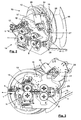
- the seal 1 is supplied from the temporary storage roller 10 by means of the guide roller 27 having the drive 26 and the pressing rollers 28 to the other guide rollers 8, 11 and 12.
- sensors and devices for position monitoring 29 are provided in front of the guide rollers 8 and possibly also in front of the pinch rollers 9. With the two opposite guide rollers 11, 12, the seal 1 is selectively fed to the pinch roller 9.
- the two guide rollers 11 and 12 exert a defined and optionally adjustable contact pressure on the seal 1, wherein the contact pressure is carried out by means of a pneumatically or hydraulically controlled pressure diaphragm.
- a connecting element 17 is screwed, which in turn is connected by screws or other fasteners to the storage drum 15.
- FIGS. 4 and 5 After the perspective representations of FIGS. 4 and 5 is on the side facing away from the connecting element 17 of the storage drum 15 in addition a guide plate 16, for example, for robot supply lines or other lines releasably connected.
- the buffer roller 10 is slidably guided with its axis of rotation 22 on the storage drum 15 and with respect to the connecting element 17.
- the sliding surfaces 21 are in particular made FIG. 8 seen.
- the conical outer jacket 25 ensures that the winding of the seal 1 on the intermediate storage roll 10 begins at the side where the conical outer jacket 25 or the entire intermediate storage roll 10 has the smallest diameter.
- the storage drum 15 is connected via the connecting plate 20 to a robot arm, not shown, or other handling device, with the robot arm or the handling device, the entire application head 14 (see FIGS. 2 and 3 ) each additionally rotated or swung.
- the application head 14 with the temporary storage roll 10 can also be moved along the periphery directly on the adhesive surface of a motor vehicle door or door opening or other opening of the motor vehicle (eg at the edge of a sunroof opening).
- a peeling off of the protective strip is required.
Landscapes
- Engineering & Computer Science (AREA)
- Mechanical Engineering (AREA)
- Automobile Manufacture Line, Endless Track Vehicle, Trailer (AREA)
Claims (10)
- Procédé de montage d'un joint d'étanchéité (1) complètement ou partiellement périphérique sur une carrosserie de véhicule, une partie de véhicule ou une plaque d'application (7) pour le montage par raccordement de préférence sur une porte de véhicule, le procédé étant caractérisé en ce quea) le joint d'étanchéité (1) est déroulé d'un rouleau de réserve (2),b) est enroulé avec au moins un enroulement sur un rouleau de stockage intermédiaire (10),c) le rouleau de stockage intermédiaire (10) est déplacé conjointement avec une tête d'application (14) pour le montage du joint d'étanchéité (1) à l'aide d'un dispositif de manipulation ou d'un robot le long d'une ligne de la carrosserie de véhicule, de la partie de véhicule ou de la plaque d'application (7) prévue pour le montage du joint d'étanchéité (1),d) le joint d'étanchéité (1), pendant le mouvement de rotation du rouleau de stockage intermédiaire (10), est acheminé à la tête d'application (14) et y est enroulé ou enfiché, par le biais de moyens de guidage pour le guidage du joint d'étanchéité (1) avant l'application et à l'aide d'un rouleau de pressage (9) ou d'un dispositif de pressage agissant de manière similaire, sur la surface prévue sur la carrosserie de véhicule ou sur la partie de véhicule ou sur des baguettes de retenue (23) sur la plaque d'application (7), ete) lors du montage périphérique, le joint d'étanchéité (1) est déplacé au moyen du rouleau de stockage intermédiaire (10) ou de rouleaux (19) disposés sur la périphérie du rouleau de stockage intermédiaire (10) par rapport à la tête d'application (14) et en l'occurrence le joint d'étanchéité (1) est en outre enroulé ou déroulé en fonction des besoins.
- Procédé selon la revendication 1, caractérisé en ce que la tête d'application (14) et le rouleau de stockage intermédiaire (10) sont pivotés et/ou tournés en commun de manière à éviter un croisement/un mauvais enroulement ou un coincement du joint d'étanchéité (1) avec les axes du robot ou du dispositif de manipulation.
- Procédé selon la revendication 1 ou 2, caractérisé en ce que le rouleau de stockage intermédiaire (10) est déplacé par un moteur ou à l'aide d'éléments de ressort et effectue le nombre requis de tours pour enrouler et/ou dérouler le joint d'étanchéité (1).
- Dispositif de montage d'un joint d'étanchéité (1) complètement ou partiellement périphérique sur une carrosserie de véhicule, une partie de véhicule ou une plaque d'application (7) pour le montage par raccordement de préférence sur une porte de véhicule, de préférence pour mettre en oeuvre le procédé selon l'une quelconque des revendications précédentes, caractérisé par une tête d'application (14) fixée sur un bras de robot ou sur un autre dispositif de manipulation de manière rotative ou pivotante avec un rouleau de stockage intermédiaire (10) fixé de manière rotative ou fixe sur la tête d'application (14) avec une surface cylindrique lisse ou avec des rouleaux (19) rotatifs disposés sur la périphérie pour l'enroulement et/ou le déroulement d'un ou de plusieurs enroulements du joint d'étanchéité (1), des rouleaux de guidage entraînés (11, 12, 27) et un rouleau de pressage (9) ou des dispositifs de pressage agissant de manière similaire pour l'alimentation et le montage du joint d'étanchéité (1).
- Dispositif selon la revendication 4, caractérisé par des rouleaux de guidage (11, 12) pouvant être pressés contre le joint d'étanchéité (1) ou des moyens de traction entre les rouleaux et/ou d'autres moyens de transport.
- Dispositif selon la revendication 5, caractérisé en ce que les rouleaux de guidage (11, 12) ou les moyens de traction peuvent être pressés avec une force variable à l'aide d'une membrane de pression à commande pneumatique ou hydraulique contre le joint d'étanchéité (1).
- Dispositif selon la revendication 4, caractérisé en ce que les rouleaux (19) disposés à la périphérie sur le rouleau de stockage intermédiaire (10) possèdent des enveloppes extérieures coniques, cylindriques ou bombées sur lesquelles repose ou roule le joint d'étanchéité.
- Dispositif selon l'une quelconque des revendications 4 à 7, caractérisé en ce qu'une tôle de guidage (16) pour des lignes d'alimentation est fixée latéralement sur la tête d'application (14).
- Tête d'application mobile (14) pour l'alimentation et le montage d'un joint d'étanchéité (1) sur une carrosserie de véhicule, une partie de véhicule ou une plaque d'application (7) par déplacement périphérique le long d'une ligne prévue pour le montage du joint d'étanchéité (1), caractérisée en ce que la tête d'application mobile se compose- d'un rouleau de stockage intermédiaire (10) fixé de manière fixe ou rotative sur la tête d'application (14) avec une surface cylindrique lisse ou des rouleaux (19) disposés de manière rotative sur la périphérie,- d'un rouleau de pressage (9) ou de dispositifs de pressage agissant de manière similaire pour l'alimentation et le montage du joint d'étanchéité (1) et- de rouleaux de guidage (8, 11, 12, 27) entraînés, fixés sur la tête d'application (14) pour le transport du joint d'étanchéité (1) du rouleau de stockage intermédiaire (10) au rouleau de pressage (9) ou aux dispositifs de pressage correspondants.
- Tête d'application mobile (14) selon la revendication 9, caractérisée par des capteurs ou d'autres dispositifs de contrôle de position (29) disposés entre les rouleaux de guidage entraînés (8, 11, 12, 27) et/ou le rouleau de pressage (9), pour contrôler et/ou commander le transport régulier du joint d'étanchéité (1).
Applications Claiming Priority (1)
| Application Number | Priority Date | Filing Date | Title |
|---|---|---|---|
| DE102010011976A DE102010011976A1 (de) | 2010-03-19 | 2010-03-19 | Verfahren, Vorrichtung und beweglicher Applikationskopf zur Anbringung einer Dichtung an einer Kfz.-Karosserie oder einer Applikationsplatte |
Publications (3)
| Publication Number | Publication Date |
|---|---|
| EP2368738A2 EP2368738A2 (fr) | 2011-09-28 |
| EP2368738A3 EP2368738A3 (fr) | 2013-01-09 |
| EP2368738B1 true EP2368738B1 (fr) | 2014-12-10 |
Family
ID=44168063
Family Applications (1)
| Application Number | Title | Priority Date | Filing Date |
|---|---|---|---|
| EP11001355.4A Active EP2368738B1 (fr) | 2010-03-19 | 2011-02-18 | Procédé, dispositif et tête d'application mobile pour l'assemblage d'un joint d'étanchéité sur une chassis de véhicule automobile ou une plaque d'application |
Country Status (3)
| Country | Link |
|---|---|
| EP (1) | EP2368738B1 (fr) |
| DE (1) | DE102010011976A1 (fr) |
| ES (1) | ES2531566T3 (fr) |
Families Citing this family (10)
| Publication number | Priority date | Publication date | Assignee | Title |
|---|---|---|---|---|
| DE102011050751B4 (de) | 2011-05-31 | 2018-09-27 | Tesla Grohmann Automation Gmbh | Vorrichtung zum Anbringen eines Dichtungsprofils |
| DE102012112603B4 (de) | 2012-12-19 | 2024-06-27 | Dr. Ing. H.C. F. Porsche Aktiengesellschaft | Verfahren und Vorrichtung zum Anbringen eines Dichtungsprofils an Fahrzeugtüren |
| CN106736345B (zh) * | 2016-12-01 | 2018-11-23 | 扬州市飞马汽油机厂 | 割草机花键垫上料机的下料装置 |
| DE102018213110A1 (de) | 2018-08-06 | 2020-02-06 | Thyssenkrupp Ag | Applikationsvorrichtung zum Applizieren eines Dichtungsprofils und Verfahren zur Applikation |
| CN109334819A (zh) * | 2018-10-31 | 2019-02-15 | 上海大众祥源动力供应有限公司 | 一种车门密封条安装系统 |
| CN114516377B (zh) * | 2022-02-21 | 2023-02-03 | 长春涵智科技有限公司 | 一种汽车车门密封条自动滚压装置及滚压方法 |
| DE102022206369B4 (de) * | 2022-06-24 | 2024-03-07 | Thyssenkrupp Ag | Modulare Applikationsvorrichtung und modularer Baukasten zum Aufbau einer Applikationsvorrichtung |
| EP4530013A3 (fr) * | 2023-09-26 | 2025-11-26 | ATN Hölzel GmbH | Dispositif d'alimentation et d'application d'un joint d'étanchéité totalement ou partiellement périphérique, tête d'application et procédé |
| DE102024112197A1 (de) | 2024-04-30 | 2024-07-18 | Thyssenkrupp Ag | Applikationsvorrichtung und Verfahren zum Applizieren eines Löcher umfassenden Dichtungsprofils mit Lochkontrolle |
| DE102024113048A1 (de) * | 2024-05-08 | 2025-11-13 | Thyssenkrupp Ag | Transportvorrichtung zum Transport eines endlosen biegeschlaffen Bauteils, Dichtungsapplikationssystem mit Transportvorrichtung und Verfahren zum Betreiben des Dichtungsapplikationssystems |
Family Cites Families (10)
| Publication number | Priority date | Publication date | Assignee | Title |
|---|---|---|---|---|
| US5201106A (en) * | 1992-05-01 | 1993-04-13 | General Motors Of Canada Limited | Apparatus and method of the control of installing weather stripping in a door or like opening by a robot |
| DE19652459A1 (de) | 1996-12-17 | 1998-06-18 | Thyssen Industrie | Halteleiste für eine Dichtung, insbesondere in einer Applikationsanlage für Kfz-Türen |
| DE10023332B4 (de) * | 2000-05-12 | 2006-09-21 | Daimlerchrysler Ag | Vorrichtung zum Aufbringen eines Kantenschutzprofiles auf die Türöffnung einer Fahrzeugkarosserie |
| DE10138781A1 (de) | 2001-08-07 | 2003-02-20 | Volkswagen Ag | Verfahren zur Anbringung einer Dichtung an einer Fahrzeugtür |
| DE102006003095B3 (de) | 2006-01-20 | 2007-10-11 | Thyssenkrupp Drauz Nothelfer Gmbh | Verfahren und Anlage zum Applizieren einer umlaufenden Dichtung an einem Verschlussteil, insbesondere einer Tür, eines Kraftfahrzeuges |
| DE102006032139A1 (de) * | 2006-01-26 | 2007-08-23 | Volkswagen Ag | Verfahren und Vorrichtung zum Aufbringen einer Dichtung |
| DE102006056276B4 (de) * | 2006-11-29 | 2015-03-05 | Volkswagen Ag | Verfahren und Vorrichtung zum Aufbringen von Dichtungen |
| DE102007010421B4 (de) * | 2007-03-01 | 2011-02-17 | Grohmann Engineering Gmbh | Verfahren und Vorrichtung zum Anbringen von Dichtungsprofilen |
| DE102007033363C5 (de) * | 2007-06-05 | 2019-04-04 | Tesla Grohmann Automation Gmbh | Verfahren sowie Vorrichtung zum Aufbringen einer Dichtung in Form eines Dichtungsstreifens auf eine Fläche |
| DE102007058839B4 (de) | 2007-12-05 | 2011-02-24 | Grohmann Engineering Gmbh | Verfahren und eine Vorrichtung zum Anbringen von Dichtungsprofilen |
-
2010
- 2010-03-19 DE DE102010011976A patent/DE102010011976A1/de not_active Withdrawn
-
2011
- 2011-02-18 EP EP11001355.4A patent/EP2368738B1/fr active Active
- 2011-02-18 ES ES11001355.4T patent/ES2531566T3/es active Active
Also Published As
| Publication number | Publication date |
|---|---|
| EP2368738A3 (fr) | 2013-01-09 |
| ES2531566T3 (es) | 2015-03-17 |
| DE102010011976A1 (de) | 2011-09-22 |
| EP2368738A2 (fr) | 2011-09-28 |
Similar Documents
| Publication | Publication Date | Title |
|---|---|---|
| EP2368738B1 (fr) | Procédé, dispositif et tête d'application mobile pour l'assemblage d'un joint d'étanchéité sur une chassis de véhicule automobile ou une plaque d'application | |
| DE69507490T2 (de) | Verfahren und vorrichtung zum aufwickeln einer laufenden bahn in eine bahnrolle | |
| EP2688691B2 (fr) | Dispositif et procédé de prélèvement d'échantillons de bandes épaisses | |
| DE102014001414B4 (de) | Ablegekopf zum automatisierten Ablegen eines flächigen Materials, sowie Verwendung eines derartigen Ablegekopfes | |
| DE10138781A1 (de) | Verfahren zur Anbringung einer Dichtung an einer Fahrzeugtür | |
| DE102007033363C5 (de) | Verfahren sowie Vorrichtung zum Aufbringen einer Dichtung in Form eines Dichtungsstreifens auf eine Fläche | |
| DE69921179T2 (de) | Wickler und verfahren zum wickeln einer bahn | |
| EP2067645B1 (fr) | Procédé et dispositif d'application de joints d'étanchéité | |
| EP1414599A1 (fr) | Dispositif pour enrouler et derouler des feuillards preformes en metal chaud | |
| DE102013204028A1 (de) | Verarbeitungsstation zum Anbringen eines Profilelements | |
| EP0958734B1 (fr) | Presse à balles rondes pour produits agricoles | |
| EP1003617A1 (fr) | Enrouleuse rotorique | |
| DE102013002019B4 (de) | Wickelungsvorrichtung für ein strangförmiges Wickelgut und Verfahren dazu | |
| DE102011017431A1 (de) | Vorrichtung und Verfahren zum Umreifen von aufgewickelten Bunden, insbesondere von Stahlbunden | |
| EP0438674A2 (fr) | Procédé à enrouler simultanément plusieurs bandes métalliques refendues | |
| DE102014223965B4 (de) | Vorrichtung zum Aufwickeln einer Materialbahn zu einer Rolle oder zum Abwickeln der Materialbahn von der Rolle | |
| DE2516226B2 (de) | Vorrichtung zum anwinkeln eines bahnfoermigen materials, insbesondere furnierbahn | |
| EP2527289A1 (fr) | Dispositif et procédé destinés à l'application d'une fermeture à vis | |
| DE69602399T2 (de) | Gerät mit Friktionsnabe zum Bearbeiten von flächigem Material | |
| DE19836159A1 (de) | Rotorhaspel | |
| DE102013207188A1 (de) | Vorrichtung und Verfahren zum dornlosen Aufwickeln eines Metallbandes | |
| DE102016124372A1 (de) | Vorrichtung und Verfahren zur Bearbeitung eines Bandendes | |
| EP0471931B1 (fr) | Dispositif de rouleau | |
| EP4670863A1 (fr) | Dispositif et procédé d'enroulement d'un produit laminé en forme de bande sur un mandrin ou un manchon d'un dispositif enrouleur | |
| DE102008000143A1 (de) | Wickelvorrichtung |
Legal Events
| Date | Code | Title | Description |
|---|---|---|---|
| PUAI | Public reference made under article 153(3) epc to a published international application that has entered the european phase |
Free format text: ORIGINAL CODE: 0009012 |
|
| AK | Designated contracting states |
Kind code of ref document: A2 Designated state(s): AL AT BE BG CH CY CZ DE DK EE ES FI FR GB GR HR HU IE IS IT LI LT LU LV MC MK MT NL NO PL PT RO RS SE SI SK SM TR |
|
| AX | Request for extension of the european patent |
Extension state: BA ME |
|
| PUAL | Search report despatched |
Free format text: ORIGINAL CODE: 0009013 |
|
| AK | Designated contracting states |
Kind code of ref document: A3 Designated state(s): AL AT BE BG CH CY CZ DE DK EE ES FI FR GB GR HR HU IE IS IT LI LT LU LV MC MK MT NL NO PL PT RO RS SE SI SK SM TR |
|
| AX | Request for extension of the european patent |
Extension state: BA ME |
|
| RIC1 | Information provided on ipc code assigned before grant |
Ipc: B60J 10/00 20060101AFI20121204BHEP Ipc: B23P 19/04 20060101ALI20121204BHEP |
|
| 17P | Request for examination filed |
Effective date: 20130709 |
|
| RBV | Designated contracting states (corrected) |
Designated state(s): AL AT BE BG CH CY CZ DE DK EE ES FI FR GB GR HR HU IE IS IT LI LT LU LV MC MK MT NL NO PL PT RO RS SE SI SK SM TR |
|
| GRAP | Despatch of communication of intention to grant a patent |
Free format text: ORIGINAL CODE: EPIDOSNIGR1 |
|
| INTG | Intention to grant announced |
Effective date: 20140710 |
|
| GRAS | Grant fee paid |
Free format text: ORIGINAL CODE: EPIDOSNIGR3 |
|
| GRAA | (expected) grant |
Free format text: ORIGINAL CODE: 0009210 |
|
| AK | Designated contracting states |
Kind code of ref document: B1 Designated state(s): AL AT BE BG CH CY CZ DE DK EE ES FI FR GB GR HR HU IE IS IT LI LT LU LV MC MK MT NL NO PL PT RO RS SE SI SK SM TR |
|
| REG | Reference to a national code |
Ref country code: GB Ref legal event code: FG4D Free format text: NOT ENGLISH |
|
| REG | Reference to a national code |
Ref country code: CH Ref legal event code: EP |
|
| REG | Reference to a national code |
Ref country code: IE Ref legal event code: FG4D Free format text: LANGUAGE OF EP DOCUMENT: GERMAN |
|
| REG | Reference to a national code |
Ref country code: AT Ref legal event code: REF Ref document number: 700464 Country of ref document: AT Kind code of ref document: T Effective date: 20150115 |
|
| REG | Reference to a national code |
Ref country code: DE Ref legal event code: R096 Ref document number: 502011005198 Country of ref document: DE Effective date: 20150122 |
|
| REG | Reference to a national code |
Ref country code: ES Ref legal event code: FG2A Ref document number: 2531566 Country of ref document: ES Kind code of ref document: T3 Effective date: 20150317 |
|
| REG | Reference to a national code |
Ref country code: SE Ref legal event code: TRGR |
|
| REG | Reference to a national code |
Ref country code: NL Ref legal event code: VDEP Effective date: 20141210 |
|
| REG | Reference to a national code |
Ref country code: NL Ref legal event code: VDEP Effective date: 20141210 |
|
| PG25 | Lapsed in a contracting state [announced via postgrant information from national office to epo] |
Ref country code: FI Free format text: LAPSE BECAUSE OF FAILURE TO SUBMIT A TRANSLATION OF THE DESCRIPTION OR TO PAY THE FEE WITHIN THE PRESCRIBED TIME-LIMIT Effective date: 20141210 Ref country code: NO Free format text: LAPSE BECAUSE OF FAILURE TO SUBMIT A TRANSLATION OF THE DESCRIPTION OR TO PAY THE FEE WITHIN THE PRESCRIBED TIME-LIMIT Effective date: 20150310 Ref country code: LT Free format text: LAPSE BECAUSE OF FAILURE TO SUBMIT A TRANSLATION OF THE DESCRIPTION OR TO PAY THE FEE WITHIN THE PRESCRIBED TIME-LIMIT Effective date: 20141210 |
|
| REG | Reference to a national code |
Ref country code: LT Ref legal event code: MG4D |
|
| PG25 | Lapsed in a contracting state [announced via postgrant information from national office to epo] |
Ref country code: HR Free format text: LAPSE BECAUSE OF FAILURE TO SUBMIT A TRANSLATION OF THE DESCRIPTION OR TO PAY THE FEE WITHIN THE PRESCRIBED TIME-LIMIT Effective date: 20141210 Ref country code: RS Free format text: LAPSE BECAUSE OF FAILURE TO SUBMIT A TRANSLATION OF THE DESCRIPTION OR TO PAY THE FEE WITHIN THE PRESCRIBED TIME-LIMIT Effective date: 20141210 Ref country code: GR Free format text: LAPSE BECAUSE OF FAILURE TO SUBMIT A TRANSLATION OF THE DESCRIPTION OR TO PAY THE FEE WITHIN THE PRESCRIBED TIME-LIMIT Effective date: 20150311 Ref country code: LV Free format text: LAPSE BECAUSE OF FAILURE TO SUBMIT A TRANSLATION OF THE DESCRIPTION OR TO PAY THE FEE WITHIN THE PRESCRIBED TIME-LIMIT Effective date: 20141210 |
|
| PG25 | Lapsed in a contracting state [announced via postgrant information from national office to epo] |
Ref country code: NL Free format text: LAPSE BECAUSE OF FAILURE TO SUBMIT A TRANSLATION OF THE DESCRIPTION OR TO PAY THE FEE WITHIN THE PRESCRIBED TIME-LIMIT Effective date: 20141210 |
|
| PG25 | Lapsed in a contracting state [announced via postgrant information from national office to epo] |
Ref country code: PT Free format text: LAPSE BECAUSE OF FAILURE TO SUBMIT A TRANSLATION OF THE DESCRIPTION OR TO PAY THE FEE WITHIN THE PRESCRIBED TIME-LIMIT Effective date: 20150410 Ref country code: CZ Free format text: LAPSE BECAUSE OF FAILURE TO SUBMIT A TRANSLATION OF THE DESCRIPTION OR TO PAY THE FEE WITHIN THE PRESCRIBED TIME-LIMIT Effective date: 20141210 Ref country code: RO Free format text: LAPSE BECAUSE OF FAILURE TO SUBMIT A TRANSLATION OF THE DESCRIPTION OR TO PAY THE FEE WITHIN THE PRESCRIBED TIME-LIMIT Effective date: 20141210 Ref country code: EE Free format text: LAPSE BECAUSE OF FAILURE TO SUBMIT A TRANSLATION OF THE DESCRIPTION OR TO PAY THE FEE WITHIN THE PRESCRIBED TIME-LIMIT Effective date: 20141210 |
|
| REG | Reference to a national code |
Ref country code: HU Ref legal event code: AG4A Ref document number: E023855 Country of ref document: HU |
|
| PG25 | Lapsed in a contracting state [announced via postgrant information from national office to epo] |
Ref country code: IS Free format text: LAPSE BECAUSE OF FAILURE TO SUBMIT A TRANSLATION OF THE DESCRIPTION OR TO PAY THE FEE WITHIN THE PRESCRIBED TIME-LIMIT Effective date: 20150410 Ref country code: PL Free format text: LAPSE BECAUSE OF FAILURE TO SUBMIT A TRANSLATION OF THE DESCRIPTION OR TO PAY THE FEE WITHIN THE PRESCRIBED TIME-LIMIT Effective date: 20141210 |
|
| REG | Reference to a national code |
Ref country code: DE Ref legal event code: R097 Ref document number: 502011005198 Country of ref document: DE |
|
| PG25 | Lapsed in a contracting state [announced via postgrant information from national office to epo] |
Ref country code: LU Free format text: LAPSE BECAUSE OF FAILURE TO SUBMIT A TRANSLATION OF THE DESCRIPTION OR TO PAY THE FEE WITHIN THE PRESCRIBED TIME-LIMIT Effective date: 20150218 |
|
| REG | Reference to a national code |
Ref country code: CH Ref legal event code: PL |
|
| REG | Reference to a national code |
Ref country code: SK Ref legal event code: T3 Ref document number: E 18813 Country of ref document: SK |
|
| PLBE | No opposition filed within time limit |
Free format text: ORIGINAL CODE: 0009261 |
|
| STAA | Information on the status of an ep patent application or granted ep patent |
Free format text: STATUS: NO OPPOSITION FILED WITHIN TIME LIMIT |
|
| PG25 | Lapsed in a contracting state [announced via postgrant information from national office to epo] |
Ref country code: MC Free format text: LAPSE BECAUSE OF FAILURE TO SUBMIT A TRANSLATION OF THE DESCRIPTION OR TO PAY THE FEE WITHIN THE PRESCRIBED TIME-LIMIT Effective date: 20141210 Ref country code: CH Free format text: LAPSE BECAUSE OF NON-PAYMENT OF DUE FEES Effective date: 20150228 Ref country code: DK Free format text: LAPSE BECAUSE OF FAILURE TO SUBMIT A TRANSLATION OF THE DESCRIPTION OR TO PAY THE FEE WITHIN THE PRESCRIBED TIME-LIMIT Effective date: 20141210 Ref country code: LI Free format text: LAPSE BECAUSE OF NON-PAYMENT OF DUE FEES Effective date: 20150228 |
|
| 26N | No opposition filed |
Effective date: 20150911 |
|
| REG | Reference to a national code |
Ref country code: IE Ref legal event code: MM4A |
|
| REG | Reference to a national code |
Ref country code: FR Ref legal event code: ST Effective date: 20151030 |
|
| PG25 | Lapsed in a contracting state [announced via postgrant information from national office to epo] |
Ref country code: IT Free format text: LAPSE BECAUSE OF FAILURE TO SUBMIT A TRANSLATION OF THE DESCRIPTION OR TO PAY THE FEE WITHIN THE PRESCRIBED TIME-LIMIT Effective date: 20141210 |
|
| PG25 | Lapsed in a contracting state [announced via postgrant information from national office to epo] |
Ref country code: IE Free format text: LAPSE BECAUSE OF NON-PAYMENT OF DUE FEES Effective date: 20150218 |
|
| PG25 | Lapsed in a contracting state [announced via postgrant information from national office to epo] |
Ref country code: SI Free format text: LAPSE BECAUSE OF FAILURE TO SUBMIT A TRANSLATION OF THE DESCRIPTION OR TO PAY THE FEE WITHIN THE PRESCRIBED TIME-LIMIT Effective date: 20141210 Ref country code: FR Free format text: LAPSE BECAUSE OF NON-PAYMENT OF DUE FEES Effective date: 20150302 |
|
| PG25 | Lapsed in a contracting state [announced via postgrant information from national office to epo] |
Ref country code: MT Free format text: LAPSE BECAUSE OF FAILURE TO SUBMIT A TRANSLATION OF THE DESCRIPTION OR TO PAY THE FEE WITHIN THE PRESCRIBED TIME-LIMIT Effective date: 20141210 |
|
| REG | Reference to a national code |
Ref country code: AT Ref legal event code: MM01 Ref document number: 700464 Country of ref document: AT Kind code of ref document: T Effective date: 20160218 |
|
| PG25 | Lapsed in a contracting state [announced via postgrant information from national office to epo] |
Ref country code: AT Free format text: LAPSE BECAUSE OF NON-PAYMENT OF DUE FEES Effective date: 20160218 Ref country code: SM Free format text: LAPSE BECAUSE OF FAILURE TO SUBMIT A TRANSLATION OF THE DESCRIPTION OR TO PAY THE FEE WITHIN THE PRESCRIBED TIME-LIMIT Effective date: 20141210 Ref country code: BG Free format text: LAPSE BECAUSE OF FAILURE TO SUBMIT A TRANSLATION OF THE DESCRIPTION OR TO PAY THE FEE WITHIN THE PRESCRIBED TIME-LIMIT Effective date: 20141210 |
|
| PG25 | Lapsed in a contracting state [announced via postgrant information from national office to epo] |
Ref country code: CY Free format text: LAPSE BECAUSE OF FAILURE TO SUBMIT A TRANSLATION OF THE DESCRIPTION OR TO PAY THE FEE WITHIN THE PRESCRIBED TIME-LIMIT Effective date: 20141210 |
|
| PG25 | Lapsed in a contracting state [announced via postgrant information from national office to epo] |
Ref country code: BE Free format text: LAPSE BECAUSE OF NON-PAYMENT OF DUE FEES Effective date: 20150228 |
|
| PG25 | Lapsed in a contracting state [announced via postgrant information from national office to epo] |
Ref country code: TR Free format text: LAPSE BECAUSE OF FAILURE TO SUBMIT A TRANSLATION OF THE DESCRIPTION OR TO PAY THE FEE WITHIN THE PRESCRIBED TIME-LIMIT Effective date: 20141210 |
|
| PG25 | Lapsed in a contracting state [announced via postgrant information from national office to epo] |
Ref country code: MK Free format text: LAPSE BECAUSE OF FAILURE TO SUBMIT A TRANSLATION OF THE DESCRIPTION OR TO PAY THE FEE WITHIN THE PRESCRIBED TIME-LIMIT Effective date: 20141210 |
|
| PG25 | Lapsed in a contracting state [announced via postgrant information from national office to epo] |
Ref country code: AL Free format text: LAPSE BECAUSE OF FAILURE TO SUBMIT A TRANSLATION OF THE DESCRIPTION OR TO PAY THE FEE WITHIN THE PRESCRIBED TIME-LIMIT Effective date: 20141210 |
|
| REG | Reference to a national code |
Ref country code: DE Ref legal event code: R081 Ref document number: 502011005198 Country of ref document: DE Owner name: THYSSENKRUPP AUTOMOTIVE BODY SOLUTIONS GMBH, DE Free format text: FORMER OWNER: THYSSENKRUPP SYSTEM ENGINEERING GMBH, 74076 HEILBRONN, DE |
|
| PGFP | Annual fee paid to national office [announced via postgrant information from national office to epo] |
Ref country code: ES Payment date: 20250331 Year of fee payment: 15 |
|
| PGFP | Annual fee paid to national office [announced via postgrant information from national office to epo] |
Ref country code: HU Payment date: 20260220 Year of fee payment: 16 |
|
| PGFP | Annual fee paid to national office [announced via postgrant information from national office to epo] |
Ref country code: SE Payment date: 20260218 Year of fee payment: 16 |
|
| PGFP | Annual fee paid to national office [announced via postgrant information from national office to epo] |
Ref country code: GB Payment date: 20260219 Year of fee payment: 16 |
|
| PGFP | Annual fee paid to national office [announced via postgrant information from national office to epo] |
Ref country code: DE Payment date: 20260218 Year of fee payment: 16 |
|
| PGFP | Annual fee paid to national office [announced via postgrant information from national office to epo] |
Ref country code: SK Payment date: 20260210 Year of fee payment: 16 |