EP2368792A2 - Raccordement des âmes pour aile d'aéronef - Google Patents
Raccordement des âmes pour aile d'aéronef Download PDFInfo
- Publication number
- EP2368792A2 EP2368792A2 EP11155323A EP11155323A EP2368792A2 EP 2368792 A2 EP2368792 A2 EP 2368792A2 EP 11155323 A EP11155323 A EP 11155323A EP 11155323 A EP11155323 A EP 11155323A EP 2368792 A2 EP2368792 A2 EP 2368792A2
- Authority
- EP
- European Patent Office
- Prior art keywords
- web
- support body
- wing
- belt
- foot
- Prior art date
- Legal status (The legal status is an assumption and is not a legal conclusion. Google has not performed a legal analysis and makes no representation as to the accuracy of the status listed.)
- Withdrawn
Links
Images


Classifications
-
- B—PERFORMING OPERATIONS; TRANSPORTING
- B64—AIRCRAFT; AVIATION; COSMONAUTICS
- B64C—AEROPLANES; HELICOPTERS
- B64C3/00—Wings
- B64C3/18—Spars; Ribs; Stringers
- B64C3/185—Spars
-
- F—MECHANICAL ENGINEERING; LIGHTING; HEATING; WEAPONS; BLASTING
- F03—MACHINES OR ENGINES FOR LIQUIDS; WIND, SPRING, OR WEIGHT MOTORS; PRODUCING MECHANICAL POWER OR A REACTIVE PROPULSIVE THRUST, NOT OTHERWISE PROVIDED FOR
- F03D—WIND MOTORS
- F03D1/00—Wind motors with rotation axis substantially parallel to the air flow entering the rotor
- F03D1/06—Rotors
- F03D1/065—Rotors characterised by their construction elements
- F03D1/0675—Rotors characterised by their construction elements of the blades
-
- F—MECHANICAL ENGINEERING; LIGHTING; HEATING; WEAPONS; BLASTING
- F05—INDEXING SCHEMES RELATING TO ENGINES OR PUMPS IN VARIOUS SUBCLASSES OF CLASSES F01-F04
- F05B—INDEXING SCHEME RELATING TO WIND, SPRING, WEIGHT, INERTIA OR LIKE MOTORS, TO MACHINES OR ENGINES FOR LIQUIDS COVERED BY SUBCLASSES F03B, F03D AND F03G
- F05B2250/00—Geometry
- F05B2250/70—Shape
- F05B2250/71—Shape curved
- F05B2250/711—Shape curved convex
-
- Y—GENERAL TAGGING OF NEW TECHNOLOGICAL DEVELOPMENTS; GENERAL TAGGING OF CROSS-SECTIONAL TECHNOLOGIES SPANNING OVER SEVERAL SECTIONS OF THE IPC; TECHNICAL SUBJECTS COVERED BY FORMER USPC CROSS-REFERENCE ART COLLECTIONS [XRACs] AND DIGESTS
- Y02—TECHNOLOGIES OR APPLICATIONS FOR MITIGATION OR ADAPTATION AGAINST CLIMATE CHANGE
- Y02E—REDUCTION OF GREENHOUSE GAS [GHG] EMISSIONS, RELATED TO ENERGY GENERATION, TRANSMISSION OR DISTRIBUTION
- Y02E10/00—Energy generation through renewable energy sources
- Y02E10/70—Wind energy
- Y02E10/72—Wind turbines with rotation axis in wind direction
-
- Y—GENERAL TAGGING OF NEW TECHNOLOGICAL DEVELOPMENTS; GENERAL TAGGING OF CROSS-SECTIONAL TECHNOLOGIES SPANNING OVER SEVERAL SECTIONS OF THE IPC; TECHNICAL SUBJECTS COVERED BY FORMER USPC CROSS-REFERENCE ART COLLECTIONS [XRACs] AND DIGESTS
- Y02—TECHNOLOGIES OR APPLICATIONS FOR MITIGATION OR ADAPTATION AGAINST CLIMATE CHANGE
- Y02P—CLIMATE CHANGE MITIGATION TECHNOLOGIES IN THE PRODUCTION OR PROCESSING OF GOODS
- Y02P70/00—Climate change mitigation technologies in the production process for final industrial or consumer products
- Y02P70/50—Manufacturing or production processes characterised by the final manufactured product
-
- Y—GENERAL TAGGING OF NEW TECHNOLOGICAL DEVELOPMENTS; GENERAL TAGGING OF CROSS-SECTIONAL TECHNOLOGIES SPANNING OVER SEVERAL SECTIONS OF THE IPC; TECHNICAL SUBJECTS COVERED BY FORMER USPC CROSS-REFERENCE ART COLLECTIONS [XRACs] AND DIGESTS
- Y10—TECHNICAL SUBJECTS COVERED BY FORMER USPC
- Y10T—TECHNICAL SUBJECTS COVERED BY FORMER US CLASSIFICATION
- Y10T156/00—Adhesive bonding and miscellaneous chemical manufacture
- Y10T156/10—Methods of surface bonding and/or assembly therefor
-
- Y—GENERAL TAGGING OF NEW TECHNOLOGICAL DEVELOPMENTS; GENERAL TAGGING OF CROSS-SECTIONAL TECHNOLOGIES SPANNING OVER SEVERAL SECTIONS OF THE IPC; TECHNICAL SUBJECTS COVERED BY FORMER USPC CROSS-REFERENCE ART COLLECTIONS [XRACs] AND DIGESTS
- Y10—TECHNICAL SUBJECTS COVERED BY FORMER USPC
- Y10T—TECHNICAL SUBJECTS COVERED BY FORMER US CLASSIFICATION
- Y10T403/00—Joints and connections
- Y10T403/47—Molded joint
Definitions
- the invention relates to a web with two web feet, wherein the web is provided for connecting a pressure side with a suction side of a wing, wherein the web has a longitudinal extent which is transverse to the extension of the web from the suction side to the pressure side.
- the invention further relates to a wing with a corresponding web.
- the invention further relates to the use of a support body in a wing for connecting the suction side and the pressure side with a web and a method for producing a wing.
- the term of the wing includes a wing of an aircraft, a propeller of a helicopter and in particular a rotor blade of a wind turbine. If a rotor blade is referred to below in particular in connection with the description of the figures, implicitly an aerofoil of an aircraft or a propeller of a helicopter should also be meant.
- Wings that use aerodynamic lift, in particular rotor blades of wind turbines, are significantly loaded during operation.
- one or more webs are introduced or glued in between the pressure side and the suction side of the blade or the rotor blade, which extend from the inside of the shell of the blade on the pressure side to the shell of the blade on the suction side.
- a web extends at least in sections along a longitudinal extension of the wing.
- the corresponding leaf shells are preferably reinforced by straps, which contribute to increasing the stability of the wings or rotor blades.
- the webs are usually connected to the respective straps, which are arranged on the suction side and the pressure side of the wings and extend in the longitudinal extent of the wing, at least in sections.
- a bridge with two bridge feet for Connection of a pressure side with a suction side of a wing wherein the web has a longitudinal extent which is transverse to the extension of the web from the suction side to the pressure side, which is further developed in that at least one web foot has transversely to the longitudinal extent two arranged on opposite sides of the web connecting sides ,
- the longitudinal extension of the web is in this case in particular along the longitudinal extent of the wing.
- connection sides By using two arranged on opposite sides of the web connection sides, by means of which a connection can be made, for example, a belt, a stronger connection is already achieved.
- the connecting sides With an angle to each other which is smaller than 180 °, the peel stresses are correspondingly preferably reduced under load.
- the connecting sides on the two opposite sides of the web are preferably provided on both web feet.
- the connecting sides of the web or the bridge feet are oriented not only transversely to the longitudinal extent of the web, but also transversely to the extension of the web from the suction side to the pressure side.
- the connecting sides of the web foot are fork-shaped in cross-section transverse to the longitudinal extent to each other. In this case, two forks are preferably provided.
- the connecting sides are in particular formed flap-like, for example, glass fiber reinforced plastic mats, which are provided with a corresponding resin.
- the web foot is at least partially complementary in shape with a wedge-shaped or arched support body in cross-section and / or a leaf shell and / or a belt of a leaf shell of the wing.
- the leaf shell and / or the belt is also formed at least partially wedge-shaped or curved.
- the support body may be integrally formed with the blade shell and / or the belt.
- the web foot is integrally connected to the web or as an attachment to the web.
- a profile for example, an extruded profile serve.
- a wing with a web according to the invention which has been described above, and a support body, which is arranged on the suction side or pressure side inside in the wing, in particular on a belt, and is connected to a web foot solved.
- the support body preferably extends longitudinally with the wing.
- a support body is arranged both on the pressure side and on the suction side, which is connected to a respective web foot. Under connected is understood in the context of the connection in particular a bonding.
- the support body is in cross-section transversely to its longitudinal extent wedge-shaped or curved, in particular convex, formed.
- the wedge shape in particular also includes a wedge with rounded edges.
- the curved shape may represent a polygon, in particular preferably with rounded edges such as a triangle or a rhombus. Under a curved shape, in particular, a Gaussian distribution or a similar waveform understood.
- the wedge has an angle of 30 ° to 120 ° to the web, in particular from 50 ° to 90 °.
- the support body has a density of less than 200 kg / m 3 , in particular less than 100 kg / m 3 , in particular less than 35 kg / m 3 , on.
- the support body is preferably made of a foam, polyethylene, polystyrene, Polyethylbuterephthalat, balsa wood or glass fiber reinforced plastic (GRP).
- GRP glass fiber reinforced plastic
- the connection sides of the respective web foot are glued to the surfaces of the support body or are connected thereto.
- the object is further solved by the use of a support body inside the suction side and / or pressure side of a wing for connecting the suction side and / or the pressure side with a web extending from the suction side to the pressure side, wherein the support body arranged on a belt is or is integral with the strap.
- the arrangement of the support body on a belt includes in particular also a connectedness with the belt.
- the and / or each support body is connected to a belt or integral with the belt.
- the belt has in this case a corresponding support body, which is in particular preferably longitudinally axial or at least partially longitudinally extended to the wing and in cross-section transversely to its longitudinal extent wedge-shaped or curved, in particular convex, is formed.
- the curvature or the cross-sectional shape of the support body is a polygon, in particular with rounded edges such as a triangle or a rhombus.
- the convex curvature is to be understood that it is seen from the side on which the support body is arranged, just convex.
- the term longitudinal extension particularly preferably includes substantially or completely parallel to the longitudinal axis of the wing, or a curved and / or twisted (twisted) wing along the longitudinally extending contour of the wing.
- the object is achieved by a method for producing a wing having a pressure side and a suction side, wherein at least one belt is provided on the pressure side and on the suction side, wherein on at least one belt, a support body is or is applied, wherein an inventive web , which has been described above, is bonded to a support body such that the support body is fitted between the connecting sides of the web foot.
- the support body is adhesively bonded to the connecting sides of the web foot.
- a support body is fitted between the connecting sides of the web feet on each side of the web. This is in the context of the invention, the other way round to understand that the connection sides of the web pages are applied to the support body or connected to them accordingly.
- Fig. 1 shows a web connection according to the invention in a schematic three-dimensional representation.
- a support body 18 for example made of balsa wood or glass fiber reinforced plastic applied. Instead of this material, a hardened plastic foam can be used.
- the support body 18 may also be made integral with the belt and made of the same material as the belt. In this embodiment, however, the support body 18 is glued to the belt 17.
- the support body 18 has a longitudinal extension 38 ', which is substantially parallel to the longitudinal axis of the rotor blade or, under certain circumstances, can also be twisted, bent and / or braided in the same way as the belt and the rotor blade.
- the corresponding shape of the support body 18 along the longitudinal extent 38 ' corresponds to the shape of the wing or rotor blade on the corresponding leaf shell, to which the belt 17 is attached.
- laminate layers 19 are applied over the belt 17 and the support body 18 to provide a more secure connection.
- an adhesive 20 is applied and on the adhesive 20, which may be, for example, a resin, on the one hand a support pad 21 and on the other a connection side 13 and on the other hidden side a connecting side 13 'past the support body 18 glued.
- the connecting sides 13 and 13 ' are part of the web foot 11 of the web 10.
- the web 10 has a longitudinal extent 38. In Fig. 1 only a section of the corresponding components shown is shown. In the case of a wing or a rotor blade, naturally the longitudinal extent 38 or 38 'is significantly greater than in FIG Fig. 1 shown.
- Fig. 2 shows a section through a further web connection according to the invention, in which two webs 10 and 10 ', which are arranged between straps 17 and 17' of the suction side 36 and pressure side 35 of a rotor blade 37, are provided.
- the belt 17 is attached to the sheet shell 22 of the suction side and the belt 17 'on the sheet shell 22' of the pressure side 35.
- the web 10 has two web feet 12 and 12 ', the respective connecting sides 15 and 15' or 16 and 16 ' exhibit.
- the connecting sides 15 and 15 ' are connected with an adhesive 20 to the support body 18' or on the support body 18 'arranged laminate layers and on the opposite side, the connecting sides 16 and 16' with an adhesive 20 to the support body 18 '"correspondingly connected
- an angle ⁇ is shown, which represents a wedge angle. This is about 60 °.
- the support bodies here have a shape of a rounded wedge in cross section with a wedge angle ⁇ .
- the cross section can also be considered arched, in particular convex. This also applies to the support body 18 Fig. 1 , which on average shows a kind of Gaussian distribution, that is, shows a very harmonic curvature.
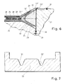
- FIGS. 3 to 6 schematically show sectional views through a part of the shape assignment in the manufacture of a web according to the invention.
- a first mold 25 is shown, on which a tear-off fabric 23 is applied as the first layer and then correspondingly a plurality of glass fiber fabric layers 24 in different lengths. The conclusion of these fiberglass fabric layers forms a tear-off fabric 23 '.
- a second mold body 26 is still provided, which has a corresponding shape as a corresponding to the connection to be used supporting body and also a third mold body 27.
- a further Abr composedgewebe 23 "introduced and possibly a flow aid, which is not shown, then the tear fabric 23 'in the direction of the arrow, wherein the arrow is shown in dashed lines, folded down on the second mold body 26 and partially on the third mold body 27 and then the shorter laminate layers 24 folded accordingly Laminate layers 24 then form a connecting side after completion of the web.
- Fig. 5 the web production is presented in an advanced process stage.
- packing 28 has been introduced into the web and further laminate layers 24 have been placed.
- the conclusion of the top-applied laminate layers 24 forms a tear-off fabric 23 "'.
- a vacuum film 29 which is sealingly placed on a sealing tape 30.
- a sealing band 30 ' is provided between the first shaped body 25 and the third shaped body 27.
- the web is then preferably made by a Resin Transfer Molding (RTM) technique, Resin Infusion Molding (RIM), and in particular, a Vacuum Assisted Resin Infusion (VAR) technique.
- RTM Resin Transfer Molding
- RIM Resin Infusion Molding
- VAR Vacuum Assisted Resin Infusion
- a conventional laminating technique can also be used, for example by using prepregs.
- a RIM or VAR method it is preferred to use a RIM or VAR method.
- a correspondingly produced web can be inserted into the corresponding sheet shells prior to the complete drying of the resin used and be connected to the respective straps or moldings which are arranged on the straps or are integral therewith ,
- Fig. 7 shows a belt shape 32, in the already corresponding recesses 33, 33 'are provided, which are provided for the formation of two support bodies on the belt or integral with the belt to be produced.
- appropriate glass fiber fabric or glass fiber fabric in the recesses 33 and 33 'and in the overlying Gurtformaussparungen 33 and 33' are introduced and impregnated with resin as usual.
- a few glass fiber fabric layers may be introduced first and as an intermediate step a support body made of a different material or prefabricated support body in the recesses 33 and 33 'are introduced to subsequently hang glass fiber fabric, which represent the respective belt after completion of production.
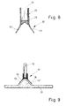
- Fig. 8 schematically shows a sectional view through a corresponding web foot of a web 10, wherein the connecting sides 13 and 13 'are correspondingly recognizable.
- the connecting sides 13 and 13 'are made of respective fiberglass fabric plies 24 integrally formed with the glass fiber fabrics 24 of the web.
- a support pad 21 is provided, which may be, for example, glass fiber reinforced plastic or balsa wood or a similar stable and lightweight material to increase the stability.
- Fig. 9 shows an alternative web 10 with a web foot 11, in which the web 10 is made as usual in the prior art and is rectangular in cross section.
- the web foot 11 has a foot profile 34, in which the web 10 is introduced, for example, is glued or screwed or riveted accordingly.
- the foot profile 34 has connecting sides 13 and 13 ', which are complementary in shape to the support body 18, which in this case is integral with the belt 17, ie the belt 17 has a corresponding shape, in which a corresponding support body is provided in sections ,
- the support body is in this case also in cross-section wedge-shaped with rounded edges.
- the support body together with overlaminates is still applied together with the belt in the belt form with a RIM process.
- the peel load can be minimized.
- the For setting the support body has setting devices.
- the foot profile 34 off Fig. 9 may be an extruded profile of a resin / powder mixture. It may also be a glass fiber reinforced plastic profile which has been laminated accordingly.
- the invention solves problems with web bonding in shell-type assemblies such as wings and rotor blades and positively influences the buckling resistance of the leaf shells.
- the production of corresponding blades or rotor blades according to the invention is very reliable and saves mold occupancy time, since the web or the webs can be bonded wet-in-wet into both shell halves without intermediate drying.
- a kind of self-centering of the webs takes place, which ensures that the webs are always glued to the correct belt position. This eliminates a very time-consuming and costly positioning tool.
Landscapes
- Engineering & Computer Science (AREA)
- Mechanical Engineering (AREA)
- Aviation & Aerospace Engineering (AREA)
- Life Sciences & Earth Sciences (AREA)
- Sustainable Development (AREA)
- Sustainable Energy (AREA)
- Chemical & Material Sciences (AREA)
- Combustion & Propulsion (AREA)
- General Engineering & Computer Science (AREA)
- Nozzles For Electric Vacuum Cleaners (AREA)
- Orthopedics, Nursing, And Contraception (AREA)
- Moulding By Coating Moulds (AREA)
- Tents Or Canopies (AREA)
Applications Claiming Priority (1)
| Application Number | Priority Date | Filing Date | Title |
|---|---|---|---|
| DE102010003114A DE102010003114A1 (de) | 2010-03-22 | 2010-03-22 | Stegverbindung |
Publications (2)
| Publication Number | Publication Date |
|---|---|
| EP2368792A2 true EP2368792A2 (fr) | 2011-09-28 |
| EP2368792A3 EP2368792A3 (fr) | 2012-11-14 |
Family
ID=44166480
Family Applications (1)
| Application Number | Title | Priority Date | Filing Date |
|---|---|---|---|
| EP11155323A Withdrawn EP2368792A3 (fr) | 2010-03-22 | 2011-02-22 | Raccordement des âmes |
Country Status (4)
| Country | Link |
|---|---|
| US (1) | US20110229333A1 (fr) |
| EP (1) | EP2368792A3 (fr) |
| CN (1) | CN102198856A (fr) |
| DE (1) | DE102010003114A1 (fr) |
Cited By (4)
| Publication number | Priority date | Publication date | Assignee | Title |
|---|---|---|---|---|
| WO2014094780A1 (fr) * | 2012-12-20 | 2014-06-26 | Vestas Wind Systems A/S | Alignement de bandes de cisaillement d'aube de turbine |
| WO2016177375A1 (fr) * | 2015-05-01 | 2016-11-10 | Vestas Wind Systems A/S | Structure de renfort pour une pale d'éolienne |
| US20160375979A1 (en) * | 2015-06-29 | 2016-12-29 | Airbus Helicopters Deutschland GmbH | Aircraft structural component that is adapted for absorbing and transmitting forces in an aircraft |
| DE102017126273A1 (de) | 2017-11-09 | 2019-05-09 | Nordex Energy Gmbh | Windenergieanlagenrotorblatt mit Steg-Gurt-Verbindung |
Families Citing this family (17)
| Publication number | Priority date | Publication date | Assignee | Title |
|---|---|---|---|---|
| US9458823B2 (en) * | 2011-12-12 | 2016-10-04 | General Electric Company | Wind turbine blade shear web connection assembly |
| DE102012204858A1 (de) * | 2012-03-27 | 2013-10-02 | Repower Systems Se | Fertigung eines Faserverbundbauteils für ein Rotorblatt |
| EP2889127B1 (fr) | 2013-12-27 | 2020-02-05 | Airbus Operations S.L. | Procédé de fabrication d'un élément raidisseur |
| US20150252780A1 (en) * | 2014-03-07 | 2015-09-10 | Siemens Aktiengesellschaft | Wind turbine blade spar web having enhanced buckling strength |
| US9745954B2 (en) * | 2014-04-30 | 2017-08-29 | General Electric Company | Rotor blade joint assembly with multi-component shear web |
| PT3165762T (pt) * | 2015-11-06 | 2024-03-22 | Nordex Energy Spain S A | Pá de turbina eólica |
| EP3380721B1 (fr) | 2015-11-26 | 2020-01-08 | Vestas Wind Systems A/S | Améliorations concernant la fabrication de pales de turbine éolienne |
| US10690111B2 (en) | 2016-12-02 | 2020-06-23 | General Electric Company | Wind turbine rotor blade |
| US10519927B2 (en) | 2017-02-20 | 2019-12-31 | General Electric Company | Shear web for a wind turbine rotor blade |
| US10828843B2 (en) | 2017-03-16 | 2020-11-10 | General Electric Company | Shear webs for wind turbine rotor blades and methods for manufacturing same |
| WO2019020152A1 (fr) * | 2017-07-27 | 2019-01-31 | Vestas Wind Systems A/S | Pied d'âme pour une âme de cisaillement |
| WO2019048535A1 (fr) * | 2017-09-07 | 2019-03-14 | Fiberline Composites A/S | Élément âme de cisaillement pour pale d'éolienne |
| US11585319B2 (en) | 2017-11-07 | 2023-02-21 | Vestas Wind Systems A/S | Wind turbine blade manufacture |
| DE102017010651A1 (de) * | 2017-11-17 | 2019-05-23 | Senvion Gmbh | Steg für ein Rotorblatt einer Windenergieanlage und Verfahren zum Herstellen eines Stegs |
| EP3788253B1 (fr) * | 2018-05-01 | 2024-06-26 | LM Wind Power A/S | Bande de cisaillement pour une pale de rotor d'éolienne |
| DE102018005030A1 (de) * | 2018-06-26 | 2020-01-02 | Senvion Gmbh | Rotorblatt mit Steg in Wabensandwichbauweise |
| WO2021228338A1 (fr) * | 2020-05-12 | 2021-11-18 | Vestas Wind Systems A/S | Pale d'éolienne |
Family Cites Families (13)
| Publication number | Priority date | Publication date | Assignee | Title |
|---|---|---|---|---|
| FR575732A (fr) * | 1923-01-12 | 1924-08-05 | Metaux Et Du Bois Soc Ind Des | Perfectionnements apportés à la construction des éléments entrant dans la constitution des engins aériens et établis par caissons accolés, notamment à celle des ailes d'aéroplanes, fuselages, organes de stabilisation et de gouverne, etc. |
| FR1195201A (fr) * | 1950-06-15 | 1959-11-16 | Giravia | Perfectionnements apportés aux voilures tournantes |
| US4113910A (en) * | 1977-04-27 | 1978-09-12 | Rockwell International Corporation | Composite load coupler for reinforcing composite structural joints |
| US4256790A (en) * | 1978-01-19 | 1981-03-17 | Rockwell International Corporation | Reinforced composite structure and method of fabrication thereof |
| US4331723A (en) * | 1980-11-05 | 1982-05-25 | The Boeing Company | Advanced composite |
| US4813202A (en) * | 1987-05-22 | 1989-03-21 | Grumman Aerospace Corporation | Structural members connected by interdigitating portions |
| US6513757B1 (en) * | 1999-07-19 | 2003-02-04 | Fuji Jukogyo Kabushiki Kaisha | Wing of composite material and method of fabricating the same |
| US6655633B1 (en) * | 2000-01-21 | 2003-12-02 | W. Cullen Chapman, Jr. | Tubular members integrated to form a structure |
| AU2001262912A1 (en) * | 2000-02-25 | 2001-09-03 | The Boeing Company | Laminated composite radius filler |
| US6374570B1 (en) * | 2000-08-25 | 2002-04-23 | Lockheed Martin Corporation | Apparatus and method for joining dissimilar materials to form a structural support member |
| US7244487B2 (en) * | 2003-04-24 | 2007-07-17 | Lockheed Martin Corporation | Apparatus, system, and method of joining structural components with a tapered tension bond joint |
| US7895745B2 (en) * | 2007-03-09 | 2011-03-01 | General Electric Company | Method for fabricating elongated airfoils for wind turbines |
| US8540833B2 (en) * | 2008-05-16 | 2013-09-24 | The Boeing Company | Reinforced stiffeners and method for making the same |
-
2010
- 2010-03-22 DE DE102010003114A patent/DE102010003114A1/de not_active Withdrawn
-
2011
- 2011-02-22 EP EP11155323A patent/EP2368792A3/fr not_active Withdrawn
- 2011-03-16 US US13/049,291 patent/US20110229333A1/en not_active Abandoned
- 2011-03-21 CN CN2011100671356A patent/CN102198856A/zh active Pending
Non-Patent Citations (1)
| Title |
|---|
| None |
Cited By (10)
| Publication number | Priority date | Publication date | Assignee | Title |
|---|---|---|---|---|
| WO2014094780A1 (fr) * | 2012-12-20 | 2014-06-26 | Vestas Wind Systems A/S | Alignement de bandes de cisaillement d'aube de turbine |
| CN104995400A (zh) * | 2012-12-20 | 2015-10-21 | 维斯塔斯风力系统有限公司 | 风轮机叶片抗剪腹板的对准 |
| CN104995400B (zh) * | 2012-12-20 | 2018-03-20 | 维斯塔斯风力系统有限公司 | 风轮机叶片抗剪腹板的对准 |
| US9932958B2 (en) | 2012-12-20 | 2018-04-03 | Vestas Wind Systems A/S | Turbine blade shear web alignment |
| WO2016177375A1 (fr) * | 2015-05-01 | 2016-11-10 | Vestas Wind Systems A/S | Structure de renfort pour une pale d'éolienne |
| US11041477B2 (en) | 2015-05-01 | 2021-06-22 | Vestas Wind Systems A/S | Reinforcing structure for a wind turbine blade |
| US20160375979A1 (en) * | 2015-06-29 | 2016-12-29 | Airbus Helicopters Deutschland GmbH | Aircraft structural component that is adapted for absorbing and transmitting forces in an aircraft |
| EP3112254A1 (fr) * | 2015-06-29 | 2017-01-04 | AIRBUS HELICOPTERS DEUTSCHLAND GmbH | Composant structural d'aéronef conçu pour absorber et transmettre des forces |
| US10399658B2 (en) * | 2015-06-29 | 2019-09-03 | Airbus Helicopters Deutschland GmbH | Aircraft structural component that is adapted for absorbing and transmitting forces in an aircraft |
| DE102017126273A1 (de) | 2017-11-09 | 2019-05-09 | Nordex Energy Gmbh | Windenergieanlagenrotorblatt mit Steg-Gurt-Verbindung |
Also Published As
| Publication number | Publication date |
|---|---|
| CN102198856A (zh) | 2011-09-28 |
| US20110229333A1 (en) | 2011-09-22 |
| EP2368792A3 (fr) | 2012-11-14 |
| DE102010003114A1 (de) | 2011-09-22 |
Similar Documents
| Publication | Publication Date | Title |
|---|---|---|
| EP2368792A2 (fr) | Raccordement des âmes pour aile d'aéronef | |
| EP2363599B1 (fr) | Pale de rotor pour une éolienne, éolienne et procédé de fabrication d'une pale de rotor | |
| EP2904262B1 (fr) | Composant composite pour la pale de rotor d'une éolienne | |
| EP3114348B1 (fr) | Procédé servant à fabriquer une pale de rotor d'une éolienne, pale de rotor et éolienne | |
| DE102011078951B4 (de) | Verfahren zum Herstellen eines Rotorblatts für eine Windenergieanlage, Sandwich-Preform und Rotorblatt für eine Windenergieanlage | |
| DE102011082664B4 (de) | Form zur Herstellung eines Steges und Steg für ein Rotorblatt einer Windenergieanlage | |
| EP2454472B1 (fr) | Pale de rotor d'éolienne et procédé de fabrication d'une pale de rotor d'éolienne | |
| EP2046564B1 (fr) | Procédé de production de plusieurs éléments composites à base de fibres | |
| DE102013201871B4 (de) | Vortexgenerator für ein Rotorblatt einer Windenergieanlage | |
| DE102014221966B4 (de) | Verfahren zum Herstellen eines Rotorblatts einer Windenergieanlage | |
| WO2018029240A1 (fr) | Membrure en éléments préfabriqués pourvues de non-tissé et son procédé de production | |
| EP2454474B1 (fr) | Pale rotorique d'une éolienne, procédé de production d'une pale rotorique et paire de courroies pour une pale rotorique | |
| DE102015007289A1 (de) | Rotorblatt, Rotorblattgurt und Verfahren zum Herstellen eines Rotorblattgurts | |
| EP3260697A1 (fr) | Sangle de bord arrière comprenant une fente à section transversale | |
| DE102011003560A1 (de) | Halbzeug für die Herstellung eines faserverstärkten Bauteils einer Windenergieanlage, insbesondere Rotorblattgurt | |
| WO2012083932A2 (fr) | Procédé de fabrication d'une pale de rotor d'une éolienne | |
| EP3551438B1 (fr) | Membrure de bord de fuite d'une pale de rotor d'une installation éolienne, pale de rotor et procédé de fabrication d'une membrure de bord de fuite | |
| EP3015702B1 (fr) | Pale de rotor pour une eolienne et procede de fabrication d'une pale de rotor | |
| DE102011077609B4 (de) | Fertigung einer Rotorblattschale | |
| EP3887670A1 (fr) | Procédé d'introduction d'une courroie de pale de rotor dans une coque de pale de rotor, moule de courroie, pale de rotor ainsi qu'éolienne | |
| DE1137321B (de) | Rotorblatt fuer Drehfluegelsysteme |
Legal Events
| Date | Code | Title | Description |
|---|---|---|---|
| PUAI | Public reference made under article 153(3) epc to a published international application that has entered the european phase |
Free format text: ORIGINAL CODE: 0009012 |
|
| AK | Designated contracting states |
Kind code of ref document: A2 Designated state(s): AL AT BE BG CH CY CZ DE DK EE ES FI FR GB GR HR HU IE IS IT LI LT LU LV MC MK MT NL NO PL PT RO RS SE SI SK SM TR |
|
| AX | Request for extension of the european patent |
Extension state: BA ME |
|
| RTI1 | Title (correction) |
Free format text: BEAM WEB CONNECTION |
|
| PUAL | Search report despatched |
Free format text: ORIGINAL CODE: 0009013 |
|
| AK | Designated contracting states |
Kind code of ref document: A3 Designated state(s): AL AT BE BG CH CY CZ DE DK EE ES FI FR GB GR HR HU IE IS IT LI LT LU LV MC MK MT NL NO PL PT RO RS SE SI SK SM TR |
|
| AX | Request for extension of the european patent |
Extension state: BA ME |
|
| RIC1 | Information provided on ipc code assigned before grant |
Ipc: F03D 1/06 20060101ALI20121008BHEP Ipc: B64C 3/18 20060101AFI20121008BHEP |
|
| STAA | Information on the status of an ep patent application or granted ep patent |
Free format text: STATUS: THE APPLICATION IS DEEMED TO BE WITHDRAWN |
|
| 18D | Application deemed to be withdrawn |
Effective date: 20130515 |