EP2369151A2 - Heizrohrmechanismus und Fahrzeugabgas-Abfallwärmenutzsystem damit - Google Patents
Heizrohrmechanismus und Fahrzeugabgas-Abfallwärmenutzsystem damit Download PDFInfo
- Publication number
- EP2369151A2 EP2369151A2 EP11155476A EP11155476A EP2369151A2 EP 2369151 A2 EP2369151 A2 EP 2369151A2 EP 11155476 A EP11155476 A EP 11155476A EP 11155476 A EP11155476 A EP 11155476A EP 2369151 A2 EP2369151 A2 EP 2369151A2
- Authority
- EP
- European Patent Office
- Prior art keywords
- water
- boiled
- pipe
- heating
- raw
- Prior art date
- Legal status (The legal status is an assumption and is not a legal conclusion. Google has not performed a legal analysis and makes no representation as to the accuracy of the status listed.)
- Withdrawn
Links
Images



Classifications
-
- F—MECHANICAL ENGINEERING; LIGHTING; HEATING; WEAPONS; BLASTING
- F01—MACHINES OR ENGINES IN GENERAL; ENGINE PLANTS IN GENERAL; STEAM ENGINES
- F01N—GAS-FLOW SILENCERS OR EXHAUST APPARATUS FOR MACHINES OR ENGINES IN GENERAL; GAS-FLOW SILENCERS OR EXHAUST APPARATUS FOR INTERNAL-COMBUSTION ENGINES
- F01N3/00—Exhaust or silencing apparatus having means for purifying, rendering innocuous, or otherwise treating exhaust
- F01N3/02—Exhaust or silencing apparatus having means for purifying, rendering innocuous, or otherwise treating exhaust for cooling, or for removing solid constituents of, exhaust
- F01N3/04—Exhaust or silencing apparatus having means for purifying, rendering innocuous, or otherwise treating exhaust for cooling, or for removing solid constituents of, exhaust using liquids
- F01N3/043—Exhaust or silencing apparatus having means for purifying, rendering innocuous, or otherwise treating exhaust for cooling, or for removing solid constituents of, exhaust using liquids without contact between liquid and exhaust gases
-
- B—PERFORMING OPERATIONS; TRANSPORTING
- B60—VEHICLES IN GENERAL
- B60H—ARRANGEMENTS OF HEATING, COOLING, VENTILATING OR OTHER AIR-TREATING DEVICES SPECIALLY ADAPTED FOR PASSENGER OR GOODS SPACES OF VEHICLES
- B60H1/00—Heating, cooling or ventilating devices
- B60H1/02—Heating, cooling or ventilating devices the heat being derived from the propulsion plant
- B60H1/14—Heating, cooling or ventilating devices the heat being derived from the propulsion plant other than from cooling liquid of the plant
- B60H1/18—Heating, cooling or ventilating devices the heat being derived from the propulsion plant other than from cooling liquid of the plant the air being heated from the plant exhaust gases
- B60H1/20—Heating, cooling or ventilating devices the heat being derived from the propulsion plant other than from cooling liquid of the plant the air being heated from the plant exhaust gases using an intermediate heat-transferring medium
-
- B—PERFORMING OPERATIONS; TRANSPORTING
- B60—VEHICLES IN GENERAL
- B60N—SEATS SPECIALLY ADAPTED FOR VEHICLES; VEHICLE PASSENGER ACCOMMODATION NOT OTHERWISE PROVIDED FOR
- B60N3/00—Arrangements or adaptations of other passenger fittings, not otherwise provided for
- B60N3/16—Arrangements or adaptations of other passenger fittings, not otherwise provided for of cooking or boiling devices
-
- F—MECHANICAL ENGINEERING; LIGHTING; HEATING; WEAPONS; BLASTING
- F01—MACHINES OR ENGINES IN GENERAL; ENGINE PLANTS IN GENERAL; STEAM ENGINES
- F01N—GAS-FLOW SILENCERS OR EXHAUST APPARATUS FOR MACHINES OR ENGINES IN GENERAL; GAS-FLOW SILENCERS OR EXHAUST APPARATUS FOR INTERNAL-COMBUSTION ENGINES
- F01N5/00—Exhaust or silencing apparatus combined or associated with devices profiting by exhaust energy
- F01N5/02—Exhaust or silencing apparatus combined or associated with devices profiting by exhaust energy the devices using heat
-
- F—MECHANICAL ENGINEERING; LIGHTING; HEATING; WEAPONS; BLASTING
- F02—COMBUSTION ENGINES; HOT-GAS OR COMBUSTION-PRODUCT ENGINE PLANTS
- F02G—HOT GAS OR COMBUSTION-PRODUCT POSITIVE-DISPLACEMENT ENGINE PLANTS; USE OF WASTE HEAT OF COMBUSTION ENGINES; NOT OTHERWISE PROVIDED FOR
- F02G5/00—Profiting from waste heat of combustion engines, not otherwise provided for
- F02G5/02—Profiting from waste heat of exhaust gases
-
- Y—GENERAL TAGGING OF NEW TECHNOLOGICAL DEVELOPMENTS; GENERAL TAGGING OF CROSS-SECTIONAL TECHNOLOGIES SPANNING OVER SEVERAL SECTIONS OF THE IPC; TECHNICAL SUBJECTS COVERED BY FORMER USPC CROSS-REFERENCE ART COLLECTIONS [XRACs] AND DIGESTS
- Y02—TECHNOLOGIES OR APPLICATIONS FOR MITIGATION OR ADAPTATION AGAINST CLIMATE CHANGE
- Y02T—CLIMATE CHANGE MITIGATION TECHNOLOGIES RELATED TO TRANSPORTATION
- Y02T10/00—Road transport of goods or passengers
- Y02T10/10—Internal combustion engine [ICE] based vehicles
- Y02T10/12—Improving ICE efficiencies
Definitions
- This invention relates to a heating pipe mechanism and a waste heat utilizing system having the same, and more particularly to a heating pipe for conveying waste exhaust gases from a vehicle and a vehicle exhaust waste heat utilizing system.
- a catalytic converter In a vehicle engine power system utilizing gasoline and diesel as primary fuels, a catalytic converter is disposed for converting incompletely combusted gases or poison materials into harmless or less harmful ones for environmental protection purposes.
- waste heat generated from the catalytic converter has a relatively high temperature to thereby become a cause of greenhouse effect.
- a portion of the waste heat generated from a catalytic converter is driven by steam to return to the engine power system, or is converted into electric energy, such that the electric energy is transmitted to the electricity system of the vehicle.
- the energy-converting efficiency of the above-mentioned process i.e., a process for converting waste heat of exhaust gases into electric energy or mechanical energy
- related equipment required for energy-converting process is complicated in structure, and has a relatively high cost. As such, numerous components are mounted to the vehicle for generating only a small amount of electricity or power, which does not meet the requirement for environmental protection.
- An object of this invention is to provide a vehicle exhaust waste heat utilizing system that utilizes waste heat of vehicle exhaust gases to process water.
- Another object of this invention is to provide a heating pipe mechanism that can be mounted easily to a vehicle for conveying waste gases of the vehicle and heating and boiling water.
- an exhaust waste heat utilizing system for a vehicle including a vehicle body, and an exhausting device mounted on the vehicle body, the exhaust waste heat utilizing system comprising:
- a heating pipe mechanism adapted for fluid connection with an output end of a catalytic converter so as to convey waste exhaust gases produced from a vehicle to thereby utilize waste heat of the catalytic converter to heat water, the heating pipe mechanism comprising:
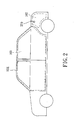
- the vehicle includes a vehicle body 104, and an exhausting device 10 mounted on a bottom portion of the vehicle body 104.
- the exhausting device 10 includes a catalytic converter 101 and an exhaust pipe 100.
- the vehicle body 104 has a front cabin area 103 for sitting of passengers, and a storage compartment area 102 for storing articles.
- the storage compartment area 102 is a rear cabin not designed for sitting of passengers.
- the storage compartment area 102 is any area not designed for sitting of passengers.
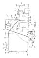
- the vehicle exhaust waste heat utilizing system includes a raw-water containing mechanism 3, a heating pipe mechanism 4 connected between and in fluid communication with the catalytic converter 101 and the exhaust pipe 100, a boiled-water conveying mechanism 5 in fluid connection with the heating pipe mechanism 4, a boiled-water processing mechanism 6 disposed on the vehicle body 104 and connected between and in fluid communication with the boiled-water conveying mechanism 5 and the raw-water containing mechanism 3, a removable boiled-water containing box 7 connected removably to and in fluid communication with the boiled-water processing mechanism 6 and disposed in the storage compartment area 102, and a thermoelectric chip module 8 mounted to the boiled-water conveying mechanism 5.
- the raw-water containing mechanism 3 includes: a hollow raw water box 30 for containing raw water; a water-supplementing pipe 31 in fluid connection with a top end of the raw water box 30 and having a water-supplementing port 310 formed in an outer surface of the vehicle body 104; a water supply pipe 32 connected between and in fluid communication with a bottom end portion of the raw water box 30 and the heating pipe mechanism 4; a raw-water passable one-way valve 33 mounted to the water supply pipe 32 for limiting flow of water toward the heating pipe mechanism 4; and a water level indicator 34 disposed on an outer surface of the raw water box 30 for indicating the level of the water contained within the raw water box 30.
- the raw water box 30 is provided with a vent pipe 300 in fluid communication with the surroundings.
- the water-supplementing port 310 may be formed directly in the raw water box 30.
- the heating pipe mechanism 4 is connected fixedly between and in fluid communication with the water supply pipe 32 and the boiled-water conveying mechanism 5.
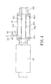
- the heating pipe mechanism 4 includes a heating pipe 41 disposed between and in fluid connection with the catalytic converter 101 and the exhaust pipe 100, and front and rear fittings 42 in fluid connection with the boiled-water conveying mechanism 5 and the water supply pipe 32, respectively.
- the heating pipe 41 includes a pair of inner and outer annular walls 413, 414 radially spaced apart from each other, a front connecting end wall 415 connected between front ends of the inner and outer annular walls 413, 414, and a rear connecting end wall 415' connected between rear ends of the inner and outer annular walls 413, 414.
- the inner and outer annular walls 413, 414 cooperate with the front and rear connecting end walls 415, 415' to define an exhaust passage 412 formed through the heating pipe mechanism 4 in a front-to-rear direction for conveying exhaust gases produced from the vehicle, and a heating compartment 411 disposed around and spaced apart from the exhaust passage 412.
- the front and rear fittings 42 are disposed respectively on a top end portion of a front end portion of the outer annular wall 414 and a bottom end portion of a rear end portion of the outer annular wall 414.
- the water supply pipe 32 is in fluid connection with the rear fitting 42.
- the boiled-water conveying mechanism 5 is in fluid connection with the front fitting 42.
- the heating pipe mechanism 4 has two ends connected respectively and fixedly to the catalytic converter 101 and the exhaust pipe 100, so as to allow waste gases discharged from the catalytic converter 101 to flow into the exhaust pipe 100 through the exhaust passage 412.
- Raw water flowing from the raw water containing mechanism 3 is received within the heating compartment 411. Since the heating pipe mechanism 4 is heated by the waste gases (having a high temperature of more than 200°C) discharged from the catalytic converter 101, the raw water received within the heating compartment 411 is heated to form boiled water, which is limited by the raw-water passable one-way valve 33 to flow into the boiled-water processing mechanism 6 through the boiled-water conveying mechanism 5.
- the storage compartment area 102 is above the exhaust pipe 100 and the catalytic converter 101, the water level of the raw water box 30 is above the heating pipe mechanism 4. As such, the boiled water flows from the heating compartment 411 into the boiled-water conveying mechanism 5. Hence, raw water flows from the raw water box 30 into the heating compartment 411 until the heating compartment 411 is filled with water.
- the boiled-water conveying mechanism 5 includes a communicating pipe 51 having a lower end in fluid connection with the front fitting 44, a pair of first and second boiled-water pipes 53, 54 connected respectively to and in fluid communication with two opposite sides of an upper end of the communicating pipe 51, a first water faucet 55 in fluid connection with a front end of the first boiled-water pipe 53, a passenger-accessible water barrel 56 in fluid connection with the second boiled-water pipe 54, a second water faucet 57 mounted to and in fluid communication with the passenger-accessible water barrel 56, and a heating valve 58 connected between and in fluid communication with the front end of the first boiled-water pipe 53 and the boiled-water processing mechanism 6.
- Rear ends of the first and second boiled-water pipes 53, 54 are connected to the boiled-water processing mechanism 6.
- a front end portion (i.e., upper end portion) of the first boiled-water pipe 53 is transparent, such that the water level of the first boiled-water pipe 53 is visible.
- the first water faucet 55 is adjacent to the driver seat of the vehicle, so that the driver can conveniently access to and open the first water faucet 55.
- the heating valve 58 is disposed between the first boiled-water pipe 53 and the boiled-water processing mechanism 6, and is normally in a closed state. Upon opening the heating valve 58, high-temperature boiled water flows from the first boiled-water pipe 53 into the boiled-water processing mechanism 6.
- the passenger-accessible water barrel 56 is disposed in the front cabin area 103, and is adjacent to the rear passenger seat for receiving and storing boiled water flowing from the second boiled-water pipe 54.
- the second water faucet 57 is operable to allow boiled water to flow from the passenger-accessible water barrel 56.
- thermoelectric chip module 8 is sleeved removably on a rear end portion of the second boiled-water pipe 54, and is heated by the high-temperature boiled water flowing within the second boiled-water pipe 54 to thereby generate and output electricity to an electronic device in the vehicle, such as mobile phone or multimedia player, via a transmission cable 81 for electricity charging. Since the thermoelectric chip module 8 is well known in the art, further description thereof will be described herein.
- the boiled-water processing mechanism 6 is mounted on the vehicle body 104, and is located in the front cabin area 103 and the storage compartment area 102.
- the boiled-water processing mechanism 6 includes a hollow heating case 61 mounted in the front cabin area 103 and in fluid communication with the front end portion of the first boiled-water pipe 53, a water conduit 62 in fluid connection with the heating case 61 and extending rearwardly into the storage compartment area 102, a boiled-water storing box 63 in fluid connection with rear ends of the water conduit 62 and the second boiled-water pipe 53 and located in the storage compartment area 102, and a boiled-water passable one-way valve 64 connected between and in fluid communication with the boiled-water storing box 63 and the raw water box 30.
- the heating case 61 includes a hollow case body 611 mounted on the vehicle body 104, and a cover body 615 mounted on the case body 611.
- the case body 611 has a heating space 612 in fluid connection with the first boiled-water pipe 53 and the water conduit 62, and a temperature conservation space 613 spaced apart from and disposed above the heating space 612 and having an upper end opening 614.
- the heating valve 58 is opened, boiled water flows from the first boiled-water pipe 53 into the heating space 612.
- the heating case 61 is made of a heat-insulating material.
- the cover body 615 is disposed pivotally on the case body 611.
- the boiled-water storing box 63 includes a main box body 631, a pressure relief valve 632 mounted on a top end of the main box body 631, a condensing pipe 634 having a front end in fluid connection with the pressure relief valve 632, a water-collecting box body 635 in fluid connection with a rear end of the condensing pipe 634, a switch 636 mounted on the main box body 631, and a water-level indicator 637 mounted on a side surface of the main box body 631 for indicating the water level of the main box body 631.
- the pressure relief valve 632 has a pressure-releasing end 633 directing outwardly.
- the switch 636 is configured as a quick coupler, and permits the removable boiled-water containing box 7 to be connected removably thereto. Upon opening of the switch 636, boiled water flows from the main box body 631 into the removable boiled-water containing box 7. When the removable boiled-water containing box 7 is removed from the switch 636, it can be moved to other place.
- water Due to the presence of the boiled-water passable one-way valve 64, water is limited to flow from the main box body 631 into the raw water box 30. As such, when the water level of the main box body 631 is above the raw water box 30, or when the water pressure in the main box body 631 is higher than that in the raw water box 30, water flows from the main box body 631 into the raw water box 30 until the main box body 631 and the raw water box 30 have the same water level or the same water pressure, so as to achieve recycle use of water.
- the raw water box 30 is filled with raw water to be processed, such as tap water or mountain spring water.
- the raw water flows into the heating compartment 411 of the heating pipe mechanism 4 for boiling.
- the boiled water flows into the communicating pipe 51, and then is conveyed by the boiled-water conveying mechanism 5 into the boiled-water processing mechanism 6.
- the food is placed into the heating space 613 in the heating case 61, and the heating valve 58 is opened.
- high-temperature boiled water flows from the first boiled-water pipe 53 into the heating space 612 and then the water conduit 62.
- Flow of the boiled water through the heating space 612 results in an increase in the temperature of the heating space 613 to thereby achieve the heating or temperature conservation function.
- the heating valve 58 is closed.
- the heating valve 58 is opened or not, when the driver or the passenger sitting on the front seat desires to drink the high-temperature boiled water, it is only necessary to open the first faucet 55, thereby resulting in convenience during use. Furthermore, the front end portion of the first boiled-water pipe 53 is transparent, as described above, so as to allow the user to easily realize whether or not there is water within the first boiled-water pipe 53, thereby further resulting in convenience during use.
- the second boiled-water pipe 54 is in a normally opened state.
- the first boiled-water pipe 53 and the water conduit 62 are in a normally closed state.
- the user can realize water consumption amount from the water-level indicator 34, 637 of the raw-water containing mechanism 3 and the boiled-water storing box 63, so as to supplement raw water into the raw water box 30 via the water-supplementing pipe 31 in time.
- the boiled-water passable one-way valve 64 is disposed to prevent flow of water from the raw water box 30 into the boiled-water storing box 63 even when the water level of the raw water box 30 is above that of the boiled-water storing box 63. As a result, the boiled water in the boiled-water storing box 63 is prevented from being contaminated by any raw water.
- the switch 636 When the water level of the main box body 631 is above the switch 636, and when it is desired to take boiled water out of the vehicle for use, the switch 636 is first opened to allow for flow of the boiled water from the main box body 631 into the removable boiled-water containing box 7. Next, the removable boiled-water containing box 7 is removed from the switch 636.
- the heating pipe mechanism 4 is directly connected to the catalytic converter 101 and the exhaust pipe 100, it is convenient to install, and has a good heat exchange efficiency. Furthermore, either the catalytic converter 101 or the exhaust pipe 100 can be removed with relative ease for repair or replacement.
- the boiled-water conveying mechanism 5 includes only one passenger-accessible water barrel 56.
- each of the seats can be mounted with a passenger-accessible water barrel 56, such that each passenger can conveniently and rapidly take boiled water from the corresponding passenger-accessible water barrel 56.
- Fig. 6 shows a modified heating mechanism 4 of the second preferred embodiment of a vehicle exhaust waste heat utilizing system according to this invention.
- the modified heating pipe mechanism 4 further includes a bypass pipe 43 and a control valve 44.
- the bypass pipe 43 has two ends in fluid connection with two ends of the heating pipe 41, and bypasses the heating compartment 411.
- the control valve 44 is disposed among the catalytic converter 101, the heating pipe 41, and the bypass pipe 43, and has first and second valve portions 441, 442 perpendicular to each other.
- the control valve 44 is operable to pivot between a first valve position shown by the solid lines, where a proximate end of the bypass pipe 43 proximate to the catalytic converter 101 is closed by the control valve 44 and where a proximate end of the heating pipe 41 proximate to the catalytic converter 101 is open, and a second valve position shown by the phantom lines, where the proximate end of the heating pipe 41 is closed by the control valve 44 and where the proximate end of the bypass pipe 43 is open.
- a driving switch (not shown) for driving the control valve 44 can be disposed in proximity to a driver seat, e.g., on a gage panel or a side of the driver seat, so as to result in convenience during use.
- the driving switch may be a manual switch or an electric switch.
- Figs. 7 and 8 show the third preferred embodiment of a vehicle exhaust waste heat utilizing system according to this invention, which is similar in construction to the first preferred embodiment. The differences are described in the following.
- the main box body 631 and the raw water box 30 are open upwardly.
- the main box body 631 is disposed within the raw water box 30, such that the main box body 631 is surrounded by the raw water box 30.
- the main box body 631 is frustoconical, and has an outer diameter that is increased gradually in a downward direction.
- a communicating pipe 636 extends into the main box body 631 and through the heating case 61, and is in fluid connection with the second boiled-water pipe 54.
- the boiled-water passable one-way valve 64 is mounted to a surrounding wall of the main box body 631, and is in fluid communication with the main box body 631 and the raw water box 30.
- the heating case 61 further includes an annular cap 616 plugged into an upper end opening in an assembly of the main box body 631 and the raw water box 30.
- the case body 611 is connected integrally to an inner periphery of the cap 616, and is located within an upper end of the main box body 631.
- the cover body 615 is two-stepped, and is plugged into an upper end of the case body 611 for covering the same.
- the communicating pipe 638 extends through the cap 616.
- the case body 611 is disposed in the upper end of the main box body 631, the heat produced from the high-temperature boiled water in the main box body 631 can be utilized to increase the temperature in the case body 611. Consequently, heating and temperature conservation of the food in the case body 611 can be performed without providing the water conduit 62 (see Fig. 1 ) and the heating valve 58 (see Fig. 1 ). Furthermore, the heating case 61 can be easily removed to allow for exposure of the upper end opening of the assembly of the main box body 631 and the raw water box 30 for cleaning.
- the heating pipe mechanism 4 due to the presence of the heating pipe mechanism 4, the boiled-water conveying mechanism 5, and the boiled-water processing mechanism 6, a portion of waste heat produced from the catalytic converter 101 and the exhaust pipe 100 can be utilized to boil raw water to thereby form potable water.
- the system of this invention is suitable for continental countries.
Landscapes
- Engineering & Computer Science (AREA)
- Mechanical Engineering (AREA)
- Chemical & Material Sciences (AREA)
- Combustion & Propulsion (AREA)
- General Engineering & Computer Science (AREA)
- Physics & Mathematics (AREA)
- Transportation (AREA)
- Thermal Sciences (AREA)
- Air-Conditioning For Vehicles (AREA)
- Exhaust Gas After Treatment (AREA)
- Heat Treatment Of Water, Waste Water Or Sewage (AREA)
- Processing Of Solid Wastes (AREA)
- Heat-Pump Type And Storage Water Heaters (AREA)
Applications Claiming Priority (2)
| Application Number | Priority Date | Filing Date | Title |
|---|---|---|---|
| TW99108877 | 2010-03-25 | ||
| TW99135427 | 2010-10-18 |
Publications (2)
| Publication Number | Publication Date |
|---|---|
| EP2369151A2 true EP2369151A2 (de) | 2011-09-28 |
| EP2369151A3 EP2369151A3 (de) | 2012-08-08 |
Family
ID=44487034
Family Applications (2)
| Application Number | Title | Priority Date | Filing Date |
|---|---|---|---|
| EP11155476A Withdrawn EP2369151A3 (de) | 2010-03-25 | 2011-02-22 | Heizrohrmechanismus und Fahrzeugabgas-Abfallwärmenutzsystem damit |
| EP11159453A Withdrawn EP2369149A3 (de) | 2010-03-25 | 2011-03-23 | Heizrohrmechanismus und Fahrzeugabgas-Abfallwärmenutzsystem damit |
Family Applications After (1)
| Application Number | Title | Priority Date | Filing Date |
|---|---|---|---|
| EP11159453A Withdrawn EP2369149A3 (de) | 2010-03-25 | 2011-03-23 | Heizrohrmechanismus und Fahrzeugabgas-Abfallwärmenutzsystem damit |
Country Status (4)
| Country | Link |
|---|---|
| US (1) | US8572953B2 (de) |
| EP (2) | EP2369151A3 (de) |
| JP (1) | JP2011202659A (de) |
| TW (1) | TW201139839A (de) |
Cited By (1)
| Publication number | Priority date | Publication date | Assignee | Title |
|---|---|---|---|---|
| CN104648208A (zh) * | 2014-06-21 | 2015-05-27 | 柳州聚龙科技有限公司 | 汽车排气管加热装置 |
Families Citing this family (1)
| Publication number | Priority date | Publication date | Assignee | Title |
|---|---|---|---|---|
| CN108795710A (zh) * | 2018-06-12 | 2018-11-13 | 合肥丰洁生物科技有限公司 | 一种节能环保的生物培养箱 |
Family Cites Families (15)
| Publication number | Priority date | Publication date | Assignee | Title |
|---|---|---|---|---|
| DE617429C (de) * | 1934-09-16 | 1935-08-19 | Gabriele Dietrich Geb Drechsel | Vorrichtung an Kraftwagen o. dgl. zum Waermen oder Kochen von Speisen u. dgl. mittels Abgases |
| JPS58191640A (ja) * | 1982-04-30 | 1983-11-08 | Kou Tatsuhide | 自動車用熱湯・冷水装置 |
| JPS6088806A (ja) * | 1983-10-21 | 1985-05-18 | Mitsui Eng & Shipbuild Co Ltd | 内燃機関の廃熱回収装置 |
| JPS61218417A (ja) * | 1985-03-22 | 1986-09-27 | Mitsubishi Electric Corp | 自動車用湯わかし装置 |
| US5398747A (en) * | 1992-09-28 | 1995-03-21 | Tufts University | Automotive vehicle auxiliary component preheating method and system |
| JPH07180539A (ja) * | 1993-12-24 | 1995-07-18 | Mitsubishi Electric Corp | 化学発熱装置 |
| US6464854B2 (en) * | 1997-12-16 | 2002-10-15 | Lynntech, Inc. | Water sources for automotive electrolyzers |
| GB2374029B (en) * | 1998-05-15 | 2002-12-31 | Arvinmeritor Inc | Exhaust system |
| US6202782B1 (en) * | 1999-05-03 | 2001-03-20 | Takefumi Hatanaka | Vehicle driving method and hybrid vehicle propulsion system |
| JP3767785B2 (ja) * | 1999-10-22 | 2006-04-19 | 本田技研工業株式会社 | エンジンの排熱回収装置 |
| JP2001173409A (ja) * | 1999-12-16 | 2001-06-26 | Honda Motor Co Ltd | 内燃機関の廃熱回収装置 |
| US6877323B2 (en) * | 2002-11-27 | 2005-04-12 | Elliott Energy Systems, Inc. | Microturbine exhaust heat augmentation system |
| TWM266357U (en) * | 2004-10-29 | 2005-06-01 | Sz-Jeng Ma | Nano air core for internal combustion device cooled by residual heat |
| TWI281001B (en) * | 2006-03-06 | 2007-05-11 | Yau-Jang Lin | Device to generate new energy by converting the waste thermal energy of internal combustion engine |
| FR2921689A1 (fr) * | 2007-10-02 | 2009-04-03 | Peugeot Citroen Automobiles Sa | Dispositif de recuperation thermique pour une ligne d'echappement avec echangeur de chaleur integre afin de recuperer l'energie thermique des gaz d'echappement d'un moteur a combustion interne |
-
2011
- 2011-02-22 EP EP11155476A patent/EP2369151A3/de not_active Withdrawn
- 2011-03-21 TW TW100109537A patent/TW201139839A/zh not_active IP Right Cessation
- 2011-03-22 US US13/065,560 patent/US8572953B2/en not_active Expired - Fee Related
- 2011-03-23 EP EP11159453A patent/EP2369149A3/de not_active Withdrawn
- 2011-03-24 JP JP2011065784A patent/JP2011202659A/ja not_active Withdrawn
Non-Patent Citations (1)
| Title |
|---|
| None |
Cited By (1)
| Publication number | Priority date | Publication date | Assignee | Title |
|---|---|---|---|---|
| CN104648208A (zh) * | 2014-06-21 | 2015-05-27 | 柳州聚龙科技有限公司 | 汽车排气管加热装置 |
Also Published As
| Publication number | Publication date |
|---|---|
| TWI398574B (de) | 2013-06-11 |
| US8572953B2 (en) | 2013-11-05 |
| EP2369151A3 (de) | 2012-08-08 |
| EP2369149A3 (de) | 2012-08-08 |
| EP2369149A2 (de) | 2011-09-28 |
| US20110232272A1 (en) | 2011-09-29 |
| TW201139839A (en) | 2011-11-16 |
| JP2011202659A (ja) | 2011-10-13 |
Similar Documents
| Publication | Publication Date | Title |
|---|---|---|
| WO1999061844A9 (en) | Heating system for potable water and relatively small areas | |
| US8572953B2 (en) | Vehicle exhaust waste heat utilizing system having a heating pipe mechanism | |
| AU2010235986B2 (en) | Domestic water heater and method for heating water for domestic use | |
| KR20200120444A (ko) | 무시동 히터를 이용한 난방 및 온수 공급장치 | |
| CN102733997A (zh) | 一种设有燃气加热器的lng客车 | |
| US20110232273A1 (en) | Heating Pipe Mechanism Having Gas Exhausting and Waste-Heat Utilizing Functions | |
| CN201314392Y (zh) | 一种可回收冷水的出水装置 | |
| CN104566938A (zh) | 轨道车辆用电热水器及水加热方法 | |
| CN102211519A (zh) | 车辆排气废热利用系统与具排气及废热利用功能的加热管机构 | |
| CN203005180U (zh) | 一种车用多功能蒸汽、开水、热水器 | |
| US8807447B2 (en) | Combined heating/hot water system for a vehicle | |
| CN2884025Y (zh) | 车船搭载式节能自动烧水保温饮水器 | |
| CN204421332U (zh) | 轨道车辆用电热水器 | |
| CN206493875U (zh) | 一种车载热饮水装置及具有其的车辆 | |
| CN102305310A (zh) | 一种带管道加热器的泡茶专用出水龙头 | |
| CN201578049U (zh) | 车载饮水机 | |
| CN2477465Y (zh) | 车用饮水机 | |
| CN100520218C (zh) | 高碳分子发热油节能电热水器 | |
| CN204388378U (zh) | 一种光电结合的客运火车饮用水供应系统 | |
| CN205026946U (zh) | 一种热水器水箱装置 | |
| KR200402014Y1 (ko) | 보온 물탱크 장치 | |
| CN203005181U (zh) | 车载热水器 | |
| RU47078U1 (ru) | Электрический кипятильник непрерывного действия | |
| CN202188222U (zh) | 带管道加热器的泡茶专用出水龙头 | |
| CN201350858Y (zh) | 利用汽车发动机冷却水进行加热的热水器 |
Legal Events
| Date | Code | Title | Description |
|---|---|---|---|
| PUAI | Public reference made under article 153(3) epc to a published international application that has entered the european phase |
Free format text: ORIGINAL CODE: 0009012 |
|
| AK | Designated contracting states |
Kind code of ref document: A2 Designated state(s): AL AT BE BG CH CY CZ DE DK EE ES FI FR GB GR HR HU IE IS IT LI LT LU LV MC MK MT NL NO PL PT RO RS SE SI SK SM TR |
|
| AX | Request for extension of the european patent |
Extension state: BA ME |
|
| PUAL | Search report despatched |
Free format text: ORIGINAL CODE: 0009013 |
|
| AK | Designated contracting states |
Kind code of ref document: A3 Designated state(s): AL AT BE BG CH CY CZ DE DK EE ES FI FR GB GR HR HU IE IS IT LI LT LU LV MC MK MT NL NO PL PT RO RS SE SI SK SM TR |
|
| AX | Request for extension of the european patent |
Extension state: BA ME |
|
| RIC1 | Information provided on ipc code assigned before grant |
Ipc: F01N 5/02 20060101AFI20120702BHEP Ipc: F02G 5/02 20060101ALI20120702BHEP Ipc: B60N 3/16 20060101ALI20120702BHEP Ipc: B60H 1/20 20060101ALI20120702BHEP |
|
| STAA | Information on the status of an ep patent application or granted ep patent |
Free format text: STATUS: THE APPLICATION IS DEEMED TO BE WITHDRAWN |
|
| 18D | Application deemed to be withdrawn |
Effective date: 20130209 |