EP2369172A2 - Machine rotative à fluide dotée d'un agencement de capteur - Google Patents
Machine rotative à fluide dotée d'un agencement de capteur Download PDFInfo
- Publication number
- EP2369172A2 EP2369172A2 EP11001518A EP11001518A EP2369172A2 EP 2369172 A2 EP2369172 A2 EP 2369172A2 EP 11001518 A EP11001518 A EP 11001518A EP 11001518 A EP11001518 A EP 11001518A EP 2369172 A2 EP2369172 A2 EP 2369172A2
- Authority
- EP
- European Patent Office
- Prior art keywords
- sensor
- housing
- rotary machine
- shaft
- encoder
- Prior art date
- Legal status (The legal status is an assumption and is not a legal conclusion. Google has not performed a legal analysis and makes no representation as to the accuracy of the status listed.)
- Granted
Links
Images


Classifications
-
- F—MECHANICAL ENGINEERING; LIGHTING; HEATING; WEAPONS; BLASTING
- F03—MACHINES OR ENGINES FOR LIQUIDS; WIND, SPRING, OR WEIGHT MOTORS; PRODUCING MECHANICAL POWER OR A REACTIVE PROPULSIVE THRUST, NOT OTHERWISE PROVIDED FOR
- F03C—POSITIVE-DISPLACEMENT ENGINES DRIVEN BY LIQUIDS
- F03C2/00—Rotary-piston engines
- F03C2/08—Rotary-piston engines of intermeshing-engagement type, i.e. with engagement of co- operating members similar to that of toothed gearing
-
- F—MECHANICAL ENGINEERING; LIGHTING; HEATING; WEAPONS; BLASTING
- F04—POSITIVE - DISPLACEMENT MACHINES FOR LIQUIDS; PUMPS FOR LIQUIDS OR ELASTIC FLUIDS
- F04C—ROTARY-PISTON, OR OSCILLATING-PISTON, POSITIVE-DISPLACEMENT MACHINES FOR LIQUIDS; ROTARY-PISTON, OR OSCILLATING-PISTON, POSITIVE-DISPLACEMENT PUMPS
- F04C2/00—Rotary-piston machines or pumps
- F04C2/08—Rotary-piston machines or pumps of intermeshing-engagement type, i.e. with engagement of co-operating members similar to that of toothed gearing
- F04C2/10—Rotary-piston machines or pumps of intermeshing-engagement type, i.e. with engagement of co-operating members similar to that of toothed gearing of internal-axis type with the outer member having more teeth or tooth-equivalents, e.g. rollers, than the inner member
- F04C2/103—Rotary-piston machines or pumps of intermeshing-engagement type, i.e. with engagement of co-operating members similar to that of toothed gearing of internal-axis type with the outer member having more teeth or tooth-equivalents, e.g. rollers, than the inner member one member having simultaneously a rotational movement about its own axis and an orbital movement
- F04C2/104—Rotary-piston machines or pumps of intermeshing-engagement type, i.e. with engagement of co-operating members similar to that of toothed gearing of internal-axis type with the outer member having more teeth or tooth-equivalents, e.g. rollers, than the inner member one member having simultaneously a rotational movement about its own axis and an orbital movement having an articulated driving shaft
-
- F—MECHANICAL ENGINEERING; LIGHTING; HEATING; WEAPONS; BLASTING
- F04—POSITIVE - DISPLACEMENT MACHINES FOR LIQUIDS; PUMPS FOR LIQUIDS OR ELASTIC FLUIDS
- F04C—ROTARY-PISTON, OR OSCILLATING-PISTON, POSITIVE-DISPLACEMENT MACHINES FOR LIQUIDS; ROTARY-PISTON, OR OSCILLATING-PISTON, POSITIVE-DISPLACEMENT PUMPS
- F04C2240/00—Components
- F04C2240/80—Other components
- F04C2240/81—Sensor, e.g. electronic sensor for control or monitoring
-
- F—MECHANICAL ENGINEERING; LIGHTING; HEATING; WEAPONS; BLASTING
- F04—POSITIVE - DISPLACEMENT MACHINES FOR LIQUIDS; PUMPS FOR LIQUIDS OR ELASTIC FLUIDS
- F04C—ROTARY-PISTON, OR OSCILLATING-PISTON, POSITIVE-DISPLACEMENT MACHINES FOR LIQUIDS; ROTARY-PISTON, OR OSCILLATING-PISTON, POSITIVE-DISPLACEMENT PUMPS
- F04C2270/00—Control; Monitoring or safety arrangements
- F04C2270/05—Speed
- F04C2270/052—Speed angular
-
- F—MECHANICAL ENGINEERING; LIGHTING; HEATING; WEAPONS; BLASTING
- F04—POSITIVE - DISPLACEMENT MACHINES FOR LIQUIDS; PUMPS FOR LIQUIDS OR ELASTIC FLUIDS
- F04C—ROTARY-PISTON, OR OSCILLATING-PISTON, POSITIVE-DISPLACEMENT MACHINES FOR LIQUIDS; ROTARY-PISTON, OR OSCILLATING-PISTON, POSITIVE-DISPLACEMENT PUMPS
- F04C2270/00—Control; Monitoring or safety arrangements
- F04C2270/86—Detection
Definitions
- the invention relates to a fluid rotary machine comprising a housing, a shaft guided out of the housing and a sensor arrangement which has an encoder, which is in operative connection with the shaft, and a receiver.
- Such a machine is off US Pat. No. 6,539,710 B2 known.
- the first section has an externally toothed gear which cooperates with an internally toothed ring gear. Between the gear and the ring gear pressure pockets are formed, which are supplied via a rotating valve spool assembly each with pressurized fluid or connected to a low pressure region.
- the gear is connected via a cardan shaft with the shaft.
- the gear is engaged with a crankpin, which transmits the orbiting motion of the gear to a sensor shaft.
- US 4,593,555 describes a hydraulic motor in which one uses a pressure sensor to determine the rotational speed of the shaft.
- US Pat. No. 6,062,123 describes a power-assisted steering device with a motor and a sensor that scans a position of a steering handwheel shaft.
- the sensor is arranged radially to the axis of the steering wheel shaft.
- DE 198 24 926 C2 describes a further hydraulic steering device, in which an inner spool is provided on its front side with a row of teeth that can be scanned by a sensor.
- DE 10 2005 036 483 B4 describes a hydraulic rotary machine whose shaft is provided with a donor having on its outer periphery a tooth structure of teeth and grooves.
- a transmitter is arranged, which directs a light beam to the threaded structure. From the thread structure of the light beam is reflected to a receiver.
- the sensor arrangements in the machines mentioned in the introduction have proven themselves in principle. But they often require a relatively complicated installation of the sensor. The sensor is then often in a position where it basically bothers. If the sensor is placed in a position where it interferes less, there is the problem that it can not directly detect the rotation of the shaft, but is in communication with the shaft through a plurality of play-engaged engagement points. A similar problem arises when the shaft can twist, for example, at high torques within the movement train.
- the invention has the object of advantageously arranging the sensor arrangement on the fluid rotary machine.
- the sensor arrangement has a receiving area in which the encoder is arranged, wherein the receiving area is in fluid communication with the interior of the housing and is sealed to the outside and the receiver outside of Housing and the receiving area is arranged.
- the receiving area seals the interior of the machine to the outside, so that one in the sensor assembly requires no opening through which a moving element is guided and must then be sealed. If you can save a seal between moving parts, this increases the reliability. The wear remains small and the susceptibility to errors decreases.
- hydraulic fluid may enter the receiving area and then simultaneously lubricate the contact surfaces of the transmitter with the housing or other element. This in turn means that the encoder can rotate virtually freely, so that an extremely small moment is required to turn the encoder. This in turn keeps the twist of the transmission element very small when using a transmission element.
- a particularly simple embodiment is to arrange the receiving area within the housing.
- the receiving area may be formed as a receiving space.
- the receiving area is formed in an end cap of the fluid rotary machine.
- the receiving area may be formed, for example, as a bore or as a recess in the front cover. There will be no through hole provided. Otherwise, the tightness would no longer be guaranteed. Again, you need in the sensor assembly no opening through which a moving element is performed. You can make the front cover or other parts of the housing made of stainless steel. A Interaction between donor and receiver is not disturbed when the interaction is due to a magnetic field.
- the encoder on a support member which cooperates with low friction with the end cover.
- the sensor arrangement has a sensor housing in which the receiving area is arranged.
- it is the sensor housing that seals the interior of the machine to the outside.
- no opening for a moving element is required in the sensor assembly, which would have to be sealed.
- the sensor housing can be manufactured as a separate component. This simplifies the production on the one hand.
- the sensor housing can be particularly well adapted to the needs of the sensor arrangement, in particular to that of the encoder.
- the encoder has a carrier element which cooperates with low friction with the sensor housing.
- the sensor arrangement even if a liquid or a fluid which penetrates into the receiving area does not have a lubricating effect per se, as is the case, for example, with water-hydraulic machines.
- the sensor housing is screwed into a front cover of the fluid rotary machine.
- the sensor housing has for this purpose, for example, an external thread, which is in engagement with a corresponding internal thread in the end cap. This simplifies the manufacture of the sensor housing and the mounting of the sensor arrangement on the machine. Moreover, in this embodiment, it is relatively easy to seal the receiving area to the outside. You just have to arrange a seal between the sensor housing and the front cover and screw the sensor housing with sufficient force in the front cover.
- the receiver is clipped onto the sensor housing. So you connect the receiver to the sensor housing with a detachable connection that can be made relatively quickly and released again.
- This has the advantage that the fluid rotary machine can be relatively easily provided with different types of sensor arrangements by replacing the receiver. Also, a repair is simplified. In a sensor arrangement, the receiver is usually the most error-prone part.
- the encoder has a magnet.
- the magnet generates the magnetic field, which is also measurable at the receiver.
- the magnetic field has to be only a few millitesla. If the magnet is moved due to a movement of the encoder caused by the shaft itself, this causes a change in the magnetic field at the recipient's place. It is also possible that several magnets are arranged on the encoder. Due to the varying magnetic field, the receiver can then draw conclusions about the movement of the encoder and thus the shaft. If the transmitter has a magnet, ideally the sensor housing will be made of a material that is non-magnetic, so that the magnetic field at the receiver is undisturbed.
- the receiver has a magnetoresistive or a Hall sensor element.
- a magnetoresistive element changes its electrical resistance when an external magnetic field is applied. This can then be read out.
- a Hall sensor element when current flows through it, provides an output voltage that is proportional to a vertical component of the magnetic field and the current. That is, even with a non-moving magnet, unlike a coil magnet arrangement, a current can always be read out.
- the transmitter and receiver elements of a Hall, rotation, speedometer generator or optical sensor With all these sensors, the rotating movement of the shaft, which is in operative connection with the encoder, can be detected.
- the transmitter has a magnet and the receiver has a Hall sensor.
- the speedometer generator supplies a voltage proportional to the speed.
- an LED can scan the sensor through a transparent sensor housing.
- the sensor arrangement preferably has an output element for outputting a quadrilateral signal.
- the output element can also output an analog current signal, which varies in particular between 2 milliamps and 20 milliamps.
- an analog voltage signal may be output that typically varies between 0.1 volts and 0.9 volts.
- a quadrilateral signal has the advantage that it is less sensitive to noise. For example, one can select a quadrature signal as a TTL signal.
- the sensor arrangement has a memory in which at least two values can be stored.
- the storage of two values in the memory can be used in particular to determine a direction of rotation of the shaft. For example, one can first normalize two values stored at different times, and then calculate a rotational speed from them taking into account the transition from 360 ° to 0 °.
- An in Fig. 1 illustrated hydraulic motor 1 has a housing 2, from which a shaft 3 is led out. On the shaft 3, a mechanical power can be removed.
- the shaft 3 is rotatable about an axis 4. It forms the part of a movement train, which in addition to the shaft 3 has a propeller shaft 5 and an externally toothed gear 6, which is arranged in an internally toothed toothed ring 7 and forms with the toothed ring 7 in a conventional manner pressure pockets which, depending on their Position are supplied with hydraulic fluid under pressure or hydraulic fluid to a low pressure port can dismiss.
- a schematically illustrated spool 8 is provided, which is connected to the shaft 3.
- the motion strand thus has, with the gear 6, a first section which orbits around the axis 4. Furthermore, the movement strand in the region of the shaft 3 has a second section which rotates about the axis 4.
- the housing 2 is closed on the opposite side of the shaft by a front cover 9. Outside on the front cover 9, a sensor arrangement 10 is arranged. However, the sensor arrangement 10 can also be arranged at least partially in the housing 2 or in the front cover 9. With the sensor assembly 10, the rotation of the shaft 3 should be detected as accurately as possible.
- the sensor arrangement 10 can have a sensor housing 11 which surrounds a receiving area in which an encoder 12 is arranged.
- the receiving area may be formed as a receiving space.
- the encoder 12 has a support member 13 which is formed of a material which cooperates with low friction with the material of the sensor housing 11.
- On the carrier element one or more donor elements are arranged.
- the encoder elements 14 are formed as magnets 29 and as permanent magnets.
- On the outside of the sensor housing 11, a receiver 15 is arranged, which by the magnetic field of the donor elements 14 is applied and passed on a non-illustrated line or wireless electrical signals containing the information about the rotational movement of the shaft 3, and a controller, not shown.
- the front cover 9 has centrally a through opening 16. Via the passage opening 16, the interior of the housing 2 is in communication with the receiving area of the sensor housing 11, so that hydraulic fluid can also penetrate from the interior of the housing 2 into the interior of the sensor housing 11. Between the sensor housing 11 and the end cover 9, a seal 17 is arranged so that the hydraulic fluid can not escape to the outside. The necessary sealing forces are ensured by a mounting arrangement with which the sensor housing 11 is attached to the front cover 9. This fastening arrangement is symbolized here by a screw 18. In fact, a plurality of screws 18 will be provided.
- the sensor housing 11 is formed of a material that is non-magnetic and that allows the magnetic field from the donor elements 14 pass, so that this magnetic field can be detected by the receiver 15.
- the encoder 12 may have a carrier element 13. It is advantageous if the support element 13 cooperates with low friction with the end cover 9. If the encoder 12 in the sensor housing 11 is described below or in the preceding, it is alternatively always possible for the encoder 12 to be arranged generally in the receiving area and in particular in the housing 2 or in the front cover 9.
- the carrier element 13 is connected via a transmission element 19 to a second section of the movement strand, which rotates about the axis 4. This is the end of the propeller shaft 5, which is engaged with the shaft 3 via a Vernierungsgeomtrie 20.
- the transmission element 19 is designed as a tachometer shaft, ie it is torsionally rigid.
- the encoder 12 thus always has exactly the same angular position as the shaft 3 with a high degree of accuracy.
- the deviation amounts to a maximum of 5 °, preferably even to a maximum of 2 ° and in particularly preferred cases to a maximum of 1 °.
- the cardan shaft has a longitudinal channel 21, which also passes through the first section of the movement strand.
- the gear 6 rotates at the same speed as the cardan shaft 5 and thus at the same speed as the transmission element 19.
- a tachometer shaft instead of a tachometer shaft, one can also use another transmission element, for example a thin metal rod or the like.
- FIG Fig. 2 In order to eliminate this deviation, one can use an embodiment as shown in FIG Fig. 2 is shown. Here, the same elements are provided with the same reference numerals.
- the transmission element 19 is formed here longer than in the embodiment according to Fig. 1 so it's immediate can be fixed in the shaft 3. A possible play in the gearing geometry 20 then no longer plays a role.
- the transmission element 19 is rotatably connected to the encoder 12 and / or with the shaft 3, but slidably connected in a direction parallel to the axis 4.
- These ends of the transmission element 19 are then guided into corresponding recesses in the transmitter 12 and / or in the shaft 3, which have a corresponding polygonal cross-section. This allows the end to be displaced axially to a certain extent in the respective recesses, so that a change in length of the transmission element 19 can be accommodated, as may arise, for example, in the event of a temperature change.
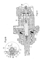
- Fig. 3 shows another hydraulic machine. Same elements as in the Fig. 1 and 2 are provided with the same reference numerals.
- the shaft 3 is connected via a tooth geometry 20 with the propeller shaft 5, which in turn is connected via a second tooth geometry 22 with the gear 6.
- a second propeller shaft 23 is provided to connect the gear 6 with the valve spool 8, which rotates together with the shaft 3 to the formed between the gear 6 and the toothed ring 7 Pressure pockets to supply the hydraulic fluid position correct.
- the transmission element 19 is connected at one end to the shaft 3 and at the other end to the encoder 12. Accordingly, the encoder 12 with high accuracy the same angular position as the shaft 3. Game in the toothing geometries 20, 22 is without influence.
- Fig. 3b shows an enlarged view of a detail B from Fig. 3a ie the sensor arrangement 10.
- Fig. 3b shows a section CC after Fig. 3c , It can be seen that the transmission element 19 has at its end, which is received in the support member 13, a square cross-section and the support member 13 has a corresponding receptacle.
- the sensor housing 11 is formed, for example, of stainless steel and the support member 13 made of a plastic, preferably PEEK (polyetheretherketones).
- magnets 29 instead of magnets 29 as donor elements 14, of course, other donor elements can be used.
- the transmitter element 14 may also have an optical marking which is externally provided by the sensor housing 11, the housing 2 or the end cover 9 scanned through can be.
- the radiation does not necessarily have to be visible radiation. It is also possible to use radiation in the infrared or ultraviolet range. Other electromagnetic waves can, if they can penetrate the sensor housing 11, the housing 2 or the front cover 9, are used for the signal transmission from the transmitter 12 to the outside.
- the sensor housing 11 is sealed by the seal 17 with respect to the end cover 9. Accordingly, although hydraulic fluid can penetrate into the interior of the sensor housing 11, but not to the outside.
- the sensor housing 11 is designed so that it can absorb the pressures occurring in the interior of the housing 2. However, no seals are required in order to seal off moving parts in the area of the sensor arrangement 10.
- Fig. 4a shows an embodiment similar to the embodiment according to Fig. 3a , The same elements are provided with the same reference numerals.
- the transmission element 19 is connected to the propeller shaft 5 and indeed at the end which faces away from the shaft 3.
- the transmission element 19 is indeed arranged eccentrically in this area.
- the transmission element 19 is subjected to bending only to an extent that it can withstand during operation in the long term.
- a second difference relates to the sensor arrangement 10, which in Fig. 4b is shown enlarged.
- the sensor housing 11 has an external thread 24 which is screwed into an internal thread 25 in the passage opening 16 in the front cover 9. As a result, both the production of the sensor housing 11 and the mounting of the sensor housing 11 is simplified.
- the sensor housing 11 may be formed as a rotating part. The assembly takes place simply in that the sensor housing 11 is screwed into the front cover 9, wherein by sealing the seal 17 seals between the end cover 9 and the sensor housing 11.
- the carrier element 13 is held by a snap ring 26 in the sensor housing 11.
- the transmission element 19 protrudes through the end cover 9, so that the support element 13, which is already preassembled in the sensor housing 11, can be placed on the transmission element 19 before the sensor housing 11 is screwed into the end cover 9.
- the sensor housing 11 has a groove 27 on its outer periphery.
- a bracket 28 shown only schematically is clipped into the groove 27. This clamp 28 holds the receiver 15 on the front side of the sensor housing 11 fixed.
- the receiver 15 can be easily assembled in this way, but also replaced.
- Magnetoresistive sensor elements 30 may comprise Wheatstone bridges, which output a signal with which the angular position of the shaft 3 or that of the encoder 3 operatively connected to the shaft 3 can be measured.
- two output signals 31 and 32 may be a sine or a cosine, as shown in FIG Fig. 5a is shown. With the help of these two output signals 31, 32, the angle can then be determined.
- Fig. 5a Normalized output signals 31, 32 are shown as a function of the angle.
- a sawtooth voltage 33 is often output.
- the sawtooth voltage is shown as a function of time. At points of lowest voltage, the angles are 0 ° or 360 °. If the receiver 15 has a magnetoresistive or a Hall sensor element 30 and the transmitter 12 has a magnet 29, then one has the necessary elements for a Hall or rotation sensor 34. Of course, other types of rotation sensors 34 as a Hall sensor 34 conceivable. Also quite different types of sensors 34 are conceivable. In particular, the previously mentioned optical sensor 34, in which the encoder 12 is scanned by electromagnetic waves, represents a further possibility. In a tacho-generator sensor 34, a voltage proportional to the speed is supplied.
- the output signals 31, 32 or the sawtooth voltage 33 can be used for further processing.
- these signals are converted into a quadrilateral signal 35.
- quadrilateral signal 35 represents a digital signal that can be recognized and used by a variety of consumers. Voltage losses in the connecting lines have no influence on signal quality. The slope of the edge typically varies between 5 microseconds and 50 milliseconds, and at least 90 pulses per cycle are typically used.
- the output signals 31, 32 are cut into segments of a predetermined frequency, the frequency depending on the desired resolution.
- an output element 36 ( Fig. 6 ) to a spend.
- a memory 37 In order to obtain a direction of rotation of the shaft 3, you can see a memory 37, as in Fig. 6 is shown, use.
- the memory 37 then stores at least two values of the angular position of the shaft 3 it can use the sinusoidal or cosinusoidal output signals 31, 32 or the sawtooth voltage 33. Taking into account the transition from 360 ° to 0 °, the direction of rotation is also displayed next to the speed.
Landscapes
- Engineering & Computer Science (AREA)
- Mechanical Engineering (AREA)
- General Engineering & Computer Science (AREA)
- Chemical & Material Sciences (AREA)
- Combustion & Propulsion (AREA)
- Transmission And Conversion Of Sensor Element Output (AREA)
- Arrangements For Transmission Of Measured Signals (AREA)
Applications Claiming Priority (1)
| Application Number | Priority Date | Filing Date | Title |
|---|---|---|---|
| DE102010012850A DE102010012850A1 (de) | 2010-03-25 | 2010-03-25 | Fluid-Rotationsmaschine mit einer Sensoranordnung |
Publications (3)
| Publication Number | Publication Date |
|---|---|
| EP2369172A2 true EP2369172A2 (fr) | 2011-09-28 |
| EP2369172A3 EP2369172A3 (fr) | 2017-05-10 |
| EP2369172B1 EP2369172B1 (fr) | 2020-02-19 |
Family
ID=44117027
Family Applications (1)
| Application Number | Title | Priority Date | Filing Date |
|---|---|---|---|
| EP11001518.7A Active EP2369172B1 (fr) | 2010-03-25 | 2011-02-24 | Machine rotative à fluide dotée d'un agencement de capteur |
Country Status (4)
| Country | Link |
|---|---|
| US (1) | US8893566B2 (fr) |
| EP (1) | EP2369172B1 (fr) |
| CN (1) | CN102207086B (fr) |
| DE (1) | DE102010012850A1 (fr) |
Cited By (1)
| Publication number | Priority date | Publication date | Assignee | Title |
|---|---|---|---|---|
| IT202200025968A1 (it) * | 2022-12-19 | 2024-06-19 | Casappa Spa | Macchina volumetrica con sensore di velocità |
Families Citing this family (4)
| Publication number | Priority date | Publication date | Assignee | Title |
|---|---|---|---|---|
| JP5401902B2 (ja) * | 2008-10-03 | 2014-01-29 | 日本電産株式会社 | モータ |
| JP5861626B2 (ja) * | 2012-12-24 | 2016-02-16 | 株式会社アドヴィックス | 内接ロータ型流体機械 |
| DE102017210426B4 (de) * | 2017-06-21 | 2024-06-27 | Vitesco Technologies Germany Gmbh | Pumpe, insbesondere Getriebeölpumpe |
| DE102024117829A1 (de) * | 2024-06-25 | 2026-01-08 | Liebherr-Aerospace Lindenberg Gmbh | Vorrichtung zur Winkelmessung und Hydraulikmotor, elektro-hydraulischer Aktuator oder Hydraulikpumpe mit einer solchen Vorrichtung |
Citations (5)
| Publication number | Priority date | Publication date | Assignee | Title |
|---|---|---|---|---|
| US4593555A (en) | 1983-12-16 | 1986-06-10 | Gary W. Krutz | Speed and torque sensor for hydraulic motor |
| DE19824926C2 (de) | 1998-06-04 | 2000-03-30 | Danfoss As | Hydraulische Lenkeinrichtung |
| US6062123A (en) | 1997-07-29 | 2000-05-16 | Koyo Seiko Co., Ltd. | Power steering system and steering-angle detecting device for use therein |
| US6539710B2 (en) | 2001-02-09 | 2003-04-01 | Eaton Corporation | Hydrostatic steering system having improved steering sensing |
| DE102005036483B4 (de) | 2005-08-03 | 2008-01-10 | Sauer-Danfoss Aps | Hydraulische Rotationsmaschine |
Family Cites Families (21)
| Publication number | Priority date | Publication date | Assignee | Title |
|---|---|---|---|---|
| JPS54177960U (fr) * | 1978-06-02 | 1979-12-15 | ||
| JPS5580745U (fr) | 1978-11-28 | 1980-06-03 | ||
| US4316144A (en) | 1979-11-23 | 1982-02-16 | General Motors Corporation | Integral mechanical and electrical vehicle speed sensor |
| GB2102129A (en) * | 1981-07-17 | 1983-01-26 | Flight Refueling Ltd | Fluid flow meters using Wiegand effect devices |
| DE3401858C1 (de) * | 1984-01-20 | 1985-02-14 | Dr.Ing.H.C. F. Porsche Ag, 7000 Stuttgart | Vorrichtung zur optoelektronischen Erfassung der Drehzahl einer Welle |
| DE8703108U1 (de) * | 1987-02-28 | 1988-03-31 | Leybold AG, 5000 Köln | Vakuumpumpe mit einer Einrichtung zur Drehzahlmessung |
| DE3912277A1 (de) * | 1989-04-14 | 1990-10-18 | Kracht Pumpen Motoren | Hydromaschine |
| US5119898A (en) | 1989-08-10 | 1992-06-09 | General Motors Corporation | Electromagnetic control apparatus for varying the driver steering effort of a hydraulic power steering system |
| US5199307A (en) * | 1990-01-20 | 1993-04-06 | Kimmon Manufacturing Co., Ltd. | Automatic power generation type flowmeter |
| JP3595348B2 (ja) * | 1993-04-30 | 2004-12-02 | 三菱重工業株式会社 | スクロール型流体機械の回転数検出装置 |
| DE19547537C1 (de) * | 1995-12-20 | 1997-02-20 | Hydraulik Nord Gmbh | Gerotormotor mit Drehzahlabtastung |
| US5933795A (en) | 1996-03-19 | 1999-08-03 | Sauer Inc. | Speed sensing device |
| GB9813447D0 (en) | 1998-06-22 | 1998-08-19 | Digital Fleet Management Ltd | A sensor |
| DE50204180D1 (de) * | 2001-02-02 | 2005-10-13 | Continental Teves Ag & Co Ohg | Aggregat für eine elektronisch geregelte bremsanlage |
| JP2003065753A (ja) | 2001-08-28 | 2003-03-05 | Showa Corp | パワーステアリングのステアリング回転角度検出装置 |
| US20060230824A1 (en) * | 2002-04-08 | 2006-10-19 | White Drive Products, Inc. | Speed sensor flange assemblies |
| DE102004060198B3 (de) | 2004-12-14 | 2006-03-30 | Pleiger Maschinenbau Gmbh & Co. Kg | Verfahren und Vorrichtung zum Steuern des Betriebs eines Radialkolbenmotors |
| GB2424452B (en) * | 2005-03-22 | 2011-01-19 | Schlumberger Holdings | Progressive cavity motor with rotor having an elastomer sleeve |
| JP2007168756A (ja) | 2005-12-26 | 2007-07-05 | Showa Corp | 電動パワーステアリング装置 |
| JP5326889B2 (ja) | 2009-07-13 | 2013-10-30 | 株式会社ジェイテクト | 電動パワーステアリング装置 |
| US20110186758A1 (en) * | 2010-02-01 | 2011-08-04 | Calbrandt, Inc. | Hydraulic Motor With Non-Contact Encoder System |
-
2010
- 2010-03-25 DE DE102010012850A patent/DE102010012850A1/de not_active Withdrawn
-
2011
- 2011-02-24 EP EP11001518.7A patent/EP2369172B1/fr active Active
- 2011-03-24 US US13/070,600 patent/US8893566B2/en active Active
- 2011-03-25 CN CN201110134430.9A patent/CN102207086B/zh active Active
Patent Citations (5)
| Publication number | Priority date | Publication date | Assignee | Title |
|---|---|---|---|---|
| US4593555A (en) | 1983-12-16 | 1986-06-10 | Gary W. Krutz | Speed and torque sensor for hydraulic motor |
| US6062123A (en) | 1997-07-29 | 2000-05-16 | Koyo Seiko Co., Ltd. | Power steering system and steering-angle detecting device for use therein |
| DE19824926C2 (de) | 1998-06-04 | 2000-03-30 | Danfoss As | Hydraulische Lenkeinrichtung |
| US6539710B2 (en) | 2001-02-09 | 2003-04-01 | Eaton Corporation | Hydrostatic steering system having improved steering sensing |
| DE102005036483B4 (de) | 2005-08-03 | 2008-01-10 | Sauer-Danfoss Aps | Hydraulische Rotationsmaschine |
Cited By (2)
| Publication number | Priority date | Publication date | Assignee | Title |
|---|---|---|---|---|
| IT202200025968A1 (it) * | 2022-12-19 | 2024-06-19 | Casappa Spa | Macchina volumetrica con sensore di velocità |
| WO2024134328A1 (fr) * | 2022-12-19 | 2024-06-27 | Casappa S.P.A. | Machine à déplacement positif équipée d'un capteur de vitesse |
Also Published As
| Publication number | Publication date |
|---|---|
| EP2369172B1 (fr) | 2020-02-19 |
| US20110236244A1 (en) | 2011-09-29 |
| DE102010012850A1 (de) | 2011-09-29 |
| EP2369172A3 (fr) | 2017-05-10 |
| US8893566B2 (en) | 2014-11-25 |
| CN102207086A (zh) | 2011-10-05 |
| CN102207086B (zh) | 2015-06-17 |
Similar Documents
| Publication | Publication Date | Title |
|---|---|---|
| DE102009048389B4 (de) | Anordnung zur Erfassung mehr als einer Umdrehung mitels Magneten als Positionsgeber | |
| EP2247925B1 (fr) | Dispositif de détection d'un angle de rotation | |
| DE10346052A1 (de) | Vorrichtung zur Erfassung des Absolutwinkels einer Welle | |
| DE102018100390A1 (de) | Magnetorheologische Bremseinrichtung | |
| DE202004007242U1 (de) | Planetenrollensystem, insbesondere für eine Vorrichtung zum Verlängern von Knochen | |
| EP1128159A2 (fr) | Arbre méchanique avec arrangement d'aimant intégré | |
| EP2369172B1 (fr) | Machine rotative à fluide dotée d'un agencement de capteur | |
| DE102019134392B4 (de) | Vorrichtung zur Bestimmung des Drehmoments und/oder des Drehwinkels zwischen einer ersten Welle und einer zweiten Welle | |
| DE102009042506B3 (de) | Verwendung eines Bandsensors zur Positionsbestimmung im Inneren eines Behälters | |
| DE102008064406A1 (de) | Anzeigeeinrichtung für einen Stellantrieb und Stellantrieb für eine Armatur | |
| EP2607856A2 (fr) | Dispositif de mesure du couple, sens de rotation et vitesse de rotation de l'arbre d'un engrenage, notamment l'arbre d'entraînement d'une mécanique d'azimut d'une éolienne | |
| EP1901040A2 (fr) | Capteur d'angle de rotation sans contact | |
| DE102005038663A1 (de) | Rundschalttisch | |
| DE19513781B4 (de) | Einrichtung zur Volumenmessung strömender Medien | |
| EP1859230B1 (fr) | Procede et dispositif pour determiner sans contact des angles de rotation d'un element rotatif | |
| EP3611088A1 (fr) | Pédalier et bicycle dotée d'un tel pédalier | |
| WO2012151708A1 (fr) | Capteur de vérin | |
| DE3743159A1 (de) | Elektrischer schubstangenantrieb | |
| DE102013000898A1 (de) | Lenkhilfeeinrichtung mit Motor und Vorrichtung zur Lagesensierung | |
| EP1312534B1 (fr) | Dispositif pour la détermination de l'angle de braquage d'un volant | |
| EP2369173A2 (fr) | Machine rotative à fluide dotée d'un agencement de capteur | |
| DE112017006417B4 (de) | Untersetzungsgetriebe, fahrzeugsitz | |
| DE102009030981A1 (de) | Einrichtung zur Verstellung der Exzentrizität für ein Kurbel-CVT-Getriebe | |
| EP3907473B1 (fr) | Dispositif de mesure d'angle pour une mesure simple tour et multitour | |
| DE10337551B4 (de) | Druckmesseinrichtung für eine Spritzgießmaschine |
Legal Events
| Date | Code | Title | Description |
|---|---|---|---|
| PUAI | Public reference made under article 153(3) epc to a published international application that has entered the european phase |
Free format text: ORIGINAL CODE: 0009012 |
|
| AK | Designated contracting states |
Kind code of ref document: A2 Designated state(s): AL AT BE BG CH CY CZ DE DK EE ES FI FR GB GR HR HU IE IS IT LI LT LU LV MC MK MT NL NO PL PT RO RS SE SI SK SM TR |
|
| AX | Request for extension of the european patent |
Extension state: BA ME |
|
| RAP1 | Party data changed (applicant data changed or rights of an application transferred) |
Owner name: DANFOSS POWER SOLUTIONS APS |
|
| PUAL | Search report despatched |
Free format text: ORIGINAL CODE: 0009013 |
|
| AK | Designated contracting states |
Kind code of ref document: A3 Designated state(s): AL AT BE BG CH CY CZ DE DK EE ES FI FR GB GR HR HU IE IS IT LI LT LU LV MC MK MT NL NO PL PT RO RS SE SI SK SM TR |
|
| AX | Request for extension of the european patent |
Extension state: BA ME |
|
| RIC1 | Information provided on ipc code assigned before grant |
Ipc: F03C 2/08 20060101AFI20170401BHEP Ipc: F04C 2/10 20060101ALI20170401BHEP |
|
| STAA | Information on the status of an ep patent application or granted ep patent |
Free format text: STATUS: REQUEST FOR EXAMINATION WAS MADE |
|
| 17P | Request for examination filed |
Effective date: 20170914 |
|
| RBV | Designated contracting states (corrected) |
Designated state(s): AL AT BE BG CH CY CZ DE DK EE ES FI FR GB GR HR HU IE IS IT LI LT LU LV MC MK MT NL NO PL PT RO RS SE SI SK SM TR |
|
| STAA | Information on the status of an ep patent application or granted ep patent |
Free format text: STATUS: EXAMINATION IS IN PROGRESS |
|
| 17Q | First examination report despatched |
Effective date: 20190208 |
|
| GRAP | Despatch of communication of intention to grant a patent |
Free format text: ORIGINAL CODE: EPIDOSNIGR1 |
|
| STAA | Information on the status of an ep patent application or granted ep patent |
Free format text: STATUS: GRANT OF PATENT IS INTENDED |
|
| INTG | Intention to grant announced |
Effective date: 20190925 |
|
| GRAS | Grant fee paid |
Free format text: ORIGINAL CODE: EPIDOSNIGR3 |
|
| GRAA | (expected) grant |
Free format text: ORIGINAL CODE: 0009210 |
|
| STAA | Information on the status of an ep patent application or granted ep patent |
Free format text: STATUS: THE PATENT HAS BEEN GRANTED |
|
| AK | Designated contracting states |
Kind code of ref document: B1 Designated state(s): AL AT BE BG CH CY CZ DE DK EE ES FI FR GB GR HR HU IE IS IT LI LT LU LV MC MK MT NL NO PL PT RO RS SE SI SK SM TR |
|
| REG | Reference to a national code |
Ref country code: GB Ref legal event code: FG4D Free format text: NOT ENGLISH |
|
| REG | Reference to a national code |
Ref country code: CH Ref legal event code: EP |
|
| REG | Reference to a national code |
Ref country code: DE Ref legal event code: R096 Ref document number: 502011016457 Country of ref document: DE |
|
| REG | Reference to a national code |
Ref country code: AT Ref legal event code: REF Ref document number: 1235263 Country of ref document: AT Kind code of ref document: T Effective date: 20200315 |
|
| REG | Reference to a national code |
Ref country code: IE Ref legal event code: FG4D Free format text: LANGUAGE OF EP DOCUMENT: GERMAN |
|
| REG | Reference to a national code |
Ref country code: NL Ref legal event code: MP Effective date: 20200219 |
|
| PG25 | Lapsed in a contracting state [announced via postgrant information from national office to epo] |
Ref country code: RS Free format text: LAPSE BECAUSE OF FAILURE TO SUBMIT A TRANSLATION OF THE DESCRIPTION OR TO PAY THE FEE WITHIN THE PRESCRIBED TIME-LIMIT Effective date: 20200219 Ref country code: FI Free format text: LAPSE BECAUSE OF FAILURE TO SUBMIT A TRANSLATION OF THE DESCRIPTION OR TO PAY THE FEE WITHIN THE PRESCRIBED TIME-LIMIT Effective date: 20200219 Ref country code: NO Free format text: LAPSE BECAUSE OF FAILURE TO SUBMIT A TRANSLATION OF THE DESCRIPTION OR TO PAY THE FEE WITHIN THE PRESCRIBED TIME-LIMIT Effective date: 20200519 |
|
| REG | Reference to a national code |
Ref country code: LT Ref legal event code: MG4D |
|
| PG25 | Lapsed in a contracting state [announced via postgrant information from national office to epo] |
Ref country code: LV Free format text: LAPSE BECAUSE OF FAILURE TO SUBMIT A TRANSLATION OF THE DESCRIPTION OR TO PAY THE FEE WITHIN THE PRESCRIBED TIME-LIMIT Effective date: 20200219 Ref country code: SE Free format text: LAPSE BECAUSE OF FAILURE TO SUBMIT A TRANSLATION OF THE DESCRIPTION OR TO PAY THE FEE WITHIN THE PRESCRIBED TIME-LIMIT Effective date: 20200219 Ref country code: GR Free format text: LAPSE BECAUSE OF FAILURE TO SUBMIT A TRANSLATION OF THE DESCRIPTION OR TO PAY THE FEE WITHIN THE PRESCRIBED TIME-LIMIT Effective date: 20200520 Ref country code: HR Free format text: LAPSE BECAUSE OF FAILURE TO SUBMIT A TRANSLATION OF THE DESCRIPTION OR TO PAY THE FEE WITHIN THE PRESCRIBED TIME-LIMIT Effective date: 20200219 Ref country code: IS Free format text: LAPSE BECAUSE OF FAILURE TO SUBMIT A TRANSLATION OF THE DESCRIPTION OR TO PAY THE FEE WITHIN THE PRESCRIBED TIME-LIMIT Effective date: 20200619 |
|
| PG25 | Lapsed in a contracting state [announced via postgrant information from national office to epo] |
Ref country code: NL Free format text: LAPSE BECAUSE OF FAILURE TO SUBMIT A TRANSLATION OF THE DESCRIPTION OR TO PAY THE FEE WITHIN THE PRESCRIBED TIME-LIMIT Effective date: 20200219 |
|
| REG | Reference to a national code |
Ref country code: CH Ref legal event code: PL |
|
| REG | Reference to a national code |
Ref country code: BE Ref legal event code: MM Effective date: 20200229 |
|
| PG25 | Lapsed in a contracting state [announced via postgrant information from national office to epo] |
Ref country code: SM Free format text: LAPSE BECAUSE OF FAILURE TO SUBMIT A TRANSLATION OF THE DESCRIPTION OR TO PAY THE FEE WITHIN THE PRESCRIBED TIME-LIMIT Effective date: 20200219 Ref country code: EE Free format text: LAPSE BECAUSE OF FAILURE TO SUBMIT A TRANSLATION OF THE DESCRIPTION OR TO PAY THE FEE WITHIN THE PRESCRIBED TIME-LIMIT Effective date: 20200219 Ref country code: SK Free format text: LAPSE BECAUSE OF FAILURE TO SUBMIT A TRANSLATION OF THE DESCRIPTION OR TO PAY THE FEE WITHIN THE PRESCRIBED TIME-LIMIT Effective date: 20200219 Ref country code: DK Free format text: LAPSE BECAUSE OF FAILURE TO SUBMIT A TRANSLATION OF THE DESCRIPTION OR TO PAY THE FEE WITHIN THE PRESCRIBED TIME-LIMIT Effective date: 20200219 Ref country code: LU Free format text: LAPSE BECAUSE OF NON-PAYMENT OF DUE FEES Effective date: 20200224 Ref country code: PT Free format text: LAPSE BECAUSE OF FAILURE TO SUBMIT A TRANSLATION OF THE DESCRIPTION OR TO PAY THE FEE WITHIN THE PRESCRIBED TIME-LIMIT Effective date: 20200712 Ref country code: CZ Free format text: LAPSE BECAUSE OF FAILURE TO SUBMIT A TRANSLATION OF THE DESCRIPTION OR TO PAY THE FEE WITHIN THE PRESCRIBED TIME-LIMIT Effective date: 20200219 Ref country code: RO Free format text: LAPSE BECAUSE OF FAILURE TO SUBMIT A TRANSLATION OF THE DESCRIPTION OR TO PAY THE FEE WITHIN THE PRESCRIBED TIME-LIMIT Effective date: 20200219 Ref country code: ES Free format text: LAPSE BECAUSE OF FAILURE TO SUBMIT A TRANSLATION OF THE DESCRIPTION OR TO PAY THE FEE WITHIN THE PRESCRIBED TIME-LIMIT Effective date: 20200219 Ref country code: LT Free format text: LAPSE BECAUSE OF FAILURE TO SUBMIT A TRANSLATION OF THE DESCRIPTION OR TO PAY THE FEE WITHIN THE PRESCRIBED TIME-LIMIT Effective date: 20200219 |
|
| REG | Reference to a national code |
Ref country code: DE Ref legal event code: R097 Ref document number: 502011016457 Country of ref document: DE |
|
| PG25 | Lapsed in a contracting state [announced via postgrant information from national office to epo] |
Ref country code: CH Free format text: LAPSE BECAUSE OF NON-PAYMENT OF DUE FEES Effective date: 20200229 Ref country code: MC Free format text: LAPSE BECAUSE OF FAILURE TO SUBMIT A TRANSLATION OF THE DESCRIPTION OR TO PAY THE FEE WITHIN THE PRESCRIBED TIME-LIMIT Effective date: 20200219 Ref country code: LI Free format text: LAPSE BECAUSE OF NON-PAYMENT OF DUE FEES Effective date: 20200229 |
|
| PLBE | No opposition filed within time limit |
Free format text: ORIGINAL CODE: 0009261 |
|
| STAA | Information on the status of an ep patent application or granted ep patent |
Free format text: STATUS: NO OPPOSITION FILED WITHIN TIME LIMIT |
|
| 26N | No opposition filed |
Effective date: 20201120 |
|
| PG25 | Lapsed in a contracting state [announced via postgrant information from national office to epo] |
Ref country code: IT Free format text: LAPSE BECAUSE OF FAILURE TO SUBMIT A TRANSLATION OF THE DESCRIPTION OR TO PAY THE FEE WITHIN THE PRESCRIBED TIME-LIMIT Effective date: 20200219 Ref country code: IE Free format text: LAPSE BECAUSE OF NON-PAYMENT OF DUE FEES Effective date: 20200224 |
|
| PG25 | Lapsed in a contracting state [announced via postgrant information from national office to epo] |
Ref country code: SI Free format text: LAPSE BECAUSE OF FAILURE TO SUBMIT A TRANSLATION OF THE DESCRIPTION OR TO PAY THE FEE WITHIN THE PRESCRIBED TIME-LIMIT Effective date: 20200219 Ref country code: BE Free format text: LAPSE BECAUSE OF NON-PAYMENT OF DUE FEES Effective date: 20200229 Ref country code: PL Free format text: LAPSE BECAUSE OF FAILURE TO SUBMIT A TRANSLATION OF THE DESCRIPTION OR TO PAY THE FEE WITHIN THE PRESCRIBED TIME-LIMIT Effective date: 20200219 |
|
| REG | Reference to a national code |
Ref country code: AT Ref legal event code: MM01 Ref document number: 1235263 Country of ref document: AT Kind code of ref document: T Effective date: 20200224 |
|
| PG25 | Lapsed in a contracting state [announced via postgrant information from national office to epo] |
Ref country code: AT Free format text: LAPSE BECAUSE OF NON-PAYMENT OF DUE FEES Effective date: 20200224 |
|
| REG | Reference to a national code |
Ref country code: DE Ref legal event code: R081 Ref document number: 502011016457 Country of ref document: DE Owner name: WHITE DRIVE MOTORS AND STEERING SP. Z.O.O., PL Free format text: FORMER OWNER: DANFOSS POWER SOLUTIONS APS, NORDBORG, DK Ref country code: DE Ref legal event code: R081 Ref document number: 502011016457 Country of ref document: DE Owner name: DANFOSS POWER SOLUTIONS SP. Z.O.O, PL Free format text: FORMER OWNER: DANFOSS POWER SOLUTIONS APS, NORDBORG, DK |
|
| REG | Reference to a national code |
Ref country code: GB Ref legal event code: 732E Free format text: REGISTERED BETWEEN 20210805 AND 20210811 |
|
| REG | Reference to a national code |
Ref country code: DE Ref legal event code: R081 Ref document number: 502011016457 Country of ref document: DE Owner name: WHITE DRIVE MOTORS AND STEERING SP. Z.O.O., PL Free format text: FORMER OWNER: DANFOSS POWER SOLUTIONS SP. Z.O.O, WROCLAW, PL |
|
| PG25 | Lapsed in a contracting state [announced via postgrant information from national office to epo] |
Ref country code: TR Free format text: LAPSE BECAUSE OF FAILURE TO SUBMIT A TRANSLATION OF THE DESCRIPTION OR TO PAY THE FEE WITHIN THE PRESCRIBED TIME-LIMIT Effective date: 20200219 Ref country code: MT Free format text: LAPSE BECAUSE OF FAILURE TO SUBMIT A TRANSLATION OF THE DESCRIPTION OR TO PAY THE FEE WITHIN THE PRESCRIBED TIME-LIMIT Effective date: 20200219 Ref country code: CY Free format text: LAPSE BECAUSE OF FAILURE TO SUBMIT A TRANSLATION OF THE DESCRIPTION OR TO PAY THE FEE WITHIN THE PRESCRIBED TIME-LIMIT Effective date: 20200219 |
|
| PG25 | Lapsed in a contracting state [announced via postgrant information from national office to epo] |
Ref country code: MK Free format text: LAPSE BECAUSE OF FAILURE TO SUBMIT A TRANSLATION OF THE DESCRIPTION OR TO PAY THE FEE WITHIN THE PRESCRIBED TIME-LIMIT Effective date: 20200219 Ref country code: AL Free format text: LAPSE BECAUSE OF FAILURE TO SUBMIT A TRANSLATION OF THE DESCRIPTION OR TO PAY THE FEE WITHIN THE PRESCRIBED TIME-LIMIT Effective date: 20200219 |
|
| P01 | Opt-out of the competence of the unified patent court (upc) registered |
Effective date: 20230516 |
|
| PGFP | Annual fee paid to national office [announced via postgrant information from national office to epo] |
Ref country code: BG Payment date: 20250221 Year of fee payment: 15 |
|
| PGFP | Annual fee paid to national office [announced via postgrant information from national office to epo] |
Ref country code: GB Payment date: 20260219 Year of fee payment: 16 |
|
| PGFP | Annual fee paid to national office [announced via postgrant information from national office to epo] |
Ref country code: DE Payment date: 20260218 Year of fee payment: 16 |
|
| PGFP | Annual fee paid to national office [announced via postgrant information from national office to epo] |
Ref country code: FR Payment date: 20260218 Year of fee payment: 16 |