EP2369178A1 - Anordnung zur Lenkung eines Blitzenergiestroms in einer Windturbine - Google Patents
Anordnung zur Lenkung eines Blitzenergiestroms in einer Windturbine Download PDFInfo
- Publication number
- EP2369178A1 EP2369178A1 EP10157977A EP10157977A EP2369178A1 EP 2369178 A1 EP2369178 A1 EP 2369178A1 EP 10157977 A EP10157977 A EP 10157977A EP 10157977 A EP10157977 A EP 10157977A EP 2369178 A1 EP2369178 A1 EP 2369178A1
- Authority
- EP
- European Patent Office
- Prior art keywords
- component
- wind turbine
- guideway
- arrangement according
- contact element
- Prior art date
- Legal status (The legal status is an assumption and is not a legal conclusion. Google has not performed a legal analysis and makes no representation as to the accuracy of the status listed.)
- Granted
Links
Images

Classifications
-
- F—MECHANICAL ENGINEERING; LIGHTING; HEATING; WEAPONS; BLASTING
- F03—MACHINES OR ENGINES FOR LIQUIDS; WIND, SPRING, OR WEIGHT MOTORS; PRODUCING MECHANICAL POWER OR A REACTIVE PROPULSIVE THRUST, NOT OTHERWISE PROVIDED FOR
- F03D—WIND MOTORS
- F03D80/00—Details, components or accessories not provided for in groups F03D1/00 - F03D17/00
- F03D80/30—Lightning protection
-
- H—ELECTRICITY
- H01—ELECTRIC ELEMENTS
- H01R—ELECTRICALLY-CONDUCTIVE CONNECTIONS; STRUCTURAL ASSOCIATIONS OF A PLURALITY OF MUTUALLY-INSULATED ELECTRICAL CONNECTING ELEMENTS; COUPLING DEVICES; CURRENT COLLECTORS
- H01R39/00—Rotary current collectors, distributors or interrupters
- H01R39/02—Details for dynamo electric machines
- H01R39/38—Brush holders
-
- H—ELECTRICITY
- H05—ELECTRIC TECHNIQUES NOT OTHERWISE PROVIDED FOR
- H05F—STATIC ELECTRICITY; NATURALLY-OCCURRING ELECTRICITY
- H05F3/00—Carrying-off electrostatic charges
- H05F3/04—Carrying-off electrostatic charges by means of spark gaps or other discharge devices
-
- Y—GENERAL TAGGING OF NEW TECHNOLOGICAL DEVELOPMENTS; GENERAL TAGGING OF CROSS-SECTIONAL TECHNOLOGIES SPANNING OVER SEVERAL SECTIONS OF THE IPC; TECHNICAL SUBJECTS COVERED BY FORMER USPC CROSS-REFERENCE ART COLLECTIONS [XRACs] AND DIGESTS
- Y02—TECHNOLOGIES OR APPLICATIONS FOR MITIGATION OR ADAPTATION AGAINST CLIMATE CHANGE
- Y02E—REDUCTION OF GREENHOUSE GAS [GHG] EMISSIONS, RELATED TO ENERGY GENERATION, TRANSMISSION OR DISTRIBUTION
- Y02E10/00—Energy generation through renewable energy sources
- Y02E10/70—Wind energy
- Y02E10/72—Wind turbines with rotation axis in wind direction
Definitions
- the present invention relates to an arrangement for directing a lightning current within a wind turbine and to a wind turbine comprising this arrangement.
- Wind turbines are located in areas that are unprotected from meteorological conditions in order to tap the full potential of the wind.
- wind turbines Due to this siting in exposed areas and due to the shape of wind turbines, there is a high probability of lightning strokes which may cause severe damage. For this reason, wind turbines are equipped with lightning protection systems for protecting their components against lightning impacts.
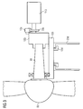
- wind turbines generally, comprise a tower 23d, a nacelle and a rotor system 83.
- the bed frame 103 of the nacelle is connected to the tower 23d via a yaw system for enabling movement of the nacelle on top of the tower 23d.
- the bed frame 103 further supports the drive train of the wind turbine which is installed inside of the nacelle.
- the rotor system 83 comprising hub and rotor blades, is connected to the drive train.
- the drive train itself comprises at least a shaft 93, a generator 113 and a braking system 13c, 23c and may further comprise a gearbox 123.
- the braking system comprises a brake calliper 13c and a brake disk 23c.
- interconnections are, beside the hub/nacelle interconnection, also the yaw clamp/tower interconnection 13d,23d on top of the tower and brake calliper/brake disk interconnections 13c,23c, wherein the brake calliper/brake disk interconnections 13c,23c may be located on the generator shaft or elsewhere in the wind turbine.
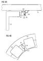
- FIG 4a and FIG 4b show a prior art realisation of a yaw system comprising a lightning current protection unit for transferring a lightning current from the nacelle 14 to the tower 24 of the wind turbine.
- FIG 4a shows a cross-sectional view and FIG 4b shows a topview of this realisation.
- the realisation comprises basically a block-shaped conductive brush 44, a spring 54 for pressing the brush 44 onto the yaw ring, a wire 144 for connecting electrically the brush 44 to the nacelle 14 and a bracket-shaped lightning brush casing 134 in which the brush 44 and the spring 54 are located.
- the parts of the unit are assembled in advance, and then, the entire assembly is mounted with bolts 154 between the yaw clamps 14a, 14b.
- this known arrangement does not function in an efficient way because the lightning current is not conducted the direct way.
- this known arrangement does not function in an efficient way because the lightning current is not conducted the direct way.
- the present invention relates to an arrangement for directing a lightning current within a wind turbine.
- the arrangement comprises a first component, a second component, a contact element and a guideway.
- One of the two components is arranged moveably in relation to the other.
- the contact element is arranged in a way that the first component is electrically connected to the second component in order to direct a lightning current within the wind turbine.
- the contact element is guided moveably by the guideway.
- the guideway is at least partly integrated in the first component.
- the inventive arrangement has the advantage that it consists of fewer parts and less complex parts compared to known lightning protection arrangements. Thus, the manufacturing and storage costs are reduced.
- the arrangement as a whole is less complex and can be mounted more easily.
- the inventive arrangement functions efficiently and the risk of failure is reduced because a lightning current is conducted over the shortest path between the components.
- FIG 1 and FIG 2 show preferred configurations and do not limit the scope of the invention.
- FIG 1 shows a cross-sectional view of a part of a wind turbine comprising a yaw clamp 11 and a tower 21.
- the yaw clamp 11 forms part of a yaw system which is mounted between the nacelle and the tower 21.
- the nacelle and the yaw clamp 11 are able to move on top of the tower 21.
- a contact element 41 is installed between the yaw clamp 11 and the tower 21.
- the contact element 41 is mounted at least partly integrated in the yaw clamp 11 in radial direction.
- a guideway 31 is provided in the yaw clamp 11.
- This guideway 31 is realised in form of a recess, for instance a radial hole.
- the guideway 31 may be constructed as a channel or as a groove.
- a first end of this contact element 41 is pressed onto the tower 21 to form a sliding contact.
- the contact element 41 is either resilient by itself or mounted resiliently. The first end of the contact element 41 may be pressed directly onto the surface of the tower 21 or onto a sliding element attached to the tower 21.
- a second end of the contact element 41 is connected to the yaw clamp 11.
- the contact element 42 comprises a conductive rod.
- the conductive rod 41 is made of a material which is able to conduct and support a lightning current within a wind turbine like carbon, graphite, metal or a composite material comprising one or more of these materials.
- the rod is made of a graphite-copper composite material. Advantages of this material are a good conductivity and a low wear rate.
- An alternative material that could be used instead is a silver-graphite composite material. This material has an even better conductivity than a copper-graphite composite.
- the conductive rod 41 comprises a first end and a second end.
- the required pressing force of the conductive rod 41 is achieved by mounting an electrically conducting spring 51 tensely between the second end of the rod 41 and the yaw clamp 11.
- an electrically conducting spring 51 tensely between the second end of the rod 41 and the yaw clamp 11.
- a constant pressing force of the rod 41 is ensured in spite of wearing of the rod 41 over the time and unevennesses of the sliding surface of the tower 21 are compensated.
- different types of springs can be used.
- the rod 41 is connected via the spring 51 to the yaw clamp 11 in a firm but detachable manner.
- this firm but detachable connection is achieved by a screw connection 61 at the outer end of the guideway 31.
- this connection is realised by mounting a grub screw 61 in the guideway 31 which engages with a threading 71 provided at the outer end of the guideway 31.
- This allows for easily changing the rod 41 or the spring 51 and it also allows for adjusting the spring force in a simple way by turning the grub screw 61.
- maintenance of the arrangement is facilitated.
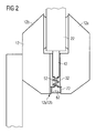
- FIG 2 shows a cross-sectional view of a part of a braking system of the wind turbine comprising a brake disc 22 which is arranged rotatably within a double acting brake calliper 12.
- the brake calliper 12 comprises a first calliper half 12a and a second calliper half 12b.
- a contact element 42 is arranged between the brake calliper 12 and the brake disc 22.
- the contact element 42 is mounted at least partly integrated in the brake calliper 12. For this reason, a guideway 32 is provided in the brake calliper 12.
- This guideway 32 is realised in form of a recess, for instance a radial hole.
- the guideway 32 may be constructed as a channel or as a groove.
- the guideway 32 is provided near the calliper set divide 12a12b.
- the brake calliper 12 comprises a first calliper half 12a and a second calliper half 12b. As shown in FIG 2 , the guideway 32 is arranged in the first calliper half 12a.
- a first end of the contact element 42 is pressed onto the brake disk 22 to form a sliding contact.
- the contact element 42 is either resilient by itself or mounted resiliently.
- the contact element 42 may be pressed directly onto the surface of the brake disk 22 or onto a sliding element attached to this brake disk 22.
- the second end of the contact element 42 is connected to the first calliper half 12a.
- the contact element 42 comprises a conductive rod.
- the conductive rod 42 is made of a material which is able to conduct and support a lightning current within a wind turbine like carbon, graphite, metal or a composite material comprising one or more of these materials.
- the rod is made of a graphite-copper composite material. Advantages of this material are a good conductivity and a low wear rate.
- An alternative material that could be used instead is a silver-graphite composite material. This material has an even better conductivity than a copper-graphite composite.
- the conductive rod 42 comprises a first end and a second end.
- the required pressing force of the rod 42 is achieved by mounting a conductive spring 52 tensely between the second end of the rod 42 and the first calliper half 12a.
- a constant pressing force of the rod 42 is ensured in spite of wearing of the rod 42 over the time, and unevennesses of the sliding surface of the brake disk 22 are compensated.
- different types of springs 52 can be used.
- the rod is connected via the spring 52 to the first calliper half 12a in a firm but detachable manner.
- this firm but detachable connection is achieved by a screw connection 62 at the outer end of the guideway 32.
- this connection is realised by mounting a grub screw 62 in the guideway 32 which engages with a threading 72 provided at the outer end of the guideway 32.
- a grub screw 62 in the guideway 32 which engages with a threading 72 provided at the outer end of the guideway 32. This allows for easily changing the rod 42 or the spring 52. It also allows for adjusting the spring force in a simple way by turning the grub screw 62. Thus, maintenance of the arrangement is facilitated.
- additional guideways 32 and contact elements 42 may be arranged in the brake calliper 12 in the first 12a and/or in the second half 12b.
- the above described braking system is located on the shaft near the generator and is used for securing the shaft, for instance for maintenance purposes.
- the braking system may also be installed elsewhere in the wind turbine.
- the wind turbine can comprise an arrangement according to the invention either in a calliper brake or in one or more yaw clamps; and it can, of course, comprise such an arrangement in one or more calliper brakes as well as in at least one yaw clamp.
- the arrangement, according to the invention can also be used to conduct a lightning current between other electrical conductive components in a wind turbine, in particular for directing a lightning current from a hub to a nacelle.
Landscapes
- Engineering & Computer Science (AREA)
- Life Sciences & Earth Sciences (AREA)
- Sustainable Development (AREA)
- Sustainable Energy (AREA)
- Chemical & Material Sciences (AREA)
- Combustion & Propulsion (AREA)
- Mechanical Engineering (AREA)
- General Engineering & Computer Science (AREA)
- Wind Motors (AREA)
Priority Applications (8)
| Application Number | Priority Date | Filing Date | Title |
|---|---|---|---|
| EP10157977.9A EP2369178B1 (de) | 2010-03-26 | 2010-03-26 | Anordnung zur Lenkung eines Blitzenergiestroms in einer Windturbine |
| DK10157977.9T DK2369178T3 (en) | 2010-03-26 | 2010-03-26 | Device for conducting a lightning current in a wind turbine |
| AU2011200951A AU2011200951B2 (en) | 2010-03-26 | 2011-03-03 | Arrangement for directing a lightning current within a wind turbine |
| US13/043,639 US8461452B2 (en) | 2010-03-26 | 2011-03-09 | Arrangement for directing a lightning current within a wind turbine |
| KR1020110025373A KR20110108273A (ko) | 2010-03-26 | 2011-03-22 | 뇌 전류를 풍력 터빈 내로 지향시키는 장치 |
| CA2735053A CA2735053C (en) | 2010-03-26 | 2011-03-24 | Arrangement for directing a lightning current within a wind turbine |
| CN201110073736.8A CN102200099B (zh) | 2010-03-26 | 2011-03-25 | 用于引导风力涡轮机内的雷电电流的装置 |
| BRPI1101091-6A BRPI1101091A2 (pt) | 2010-03-26 | 2011-03-28 | disposição para direcionar uma corrente de iluminação dentro de uma turbina eólica |
Applications Claiming Priority (1)
| Application Number | Priority Date | Filing Date | Title |
|---|---|---|---|
| EP10157977.9A EP2369178B1 (de) | 2010-03-26 | 2010-03-26 | Anordnung zur Lenkung eines Blitzenergiestroms in einer Windturbine |
Publications (2)
| Publication Number | Publication Date |
|---|---|
| EP2369178A1 true EP2369178A1 (de) | 2011-09-28 |
| EP2369178B1 EP2369178B1 (de) | 2016-05-11 |
Family
ID=42358536
Family Applications (1)
| Application Number | Title | Priority Date | Filing Date |
|---|---|---|---|
| EP10157977.9A Active EP2369178B1 (de) | 2010-03-26 | 2010-03-26 | Anordnung zur Lenkung eines Blitzenergiestroms in einer Windturbine |
Country Status (8)
| Country | Link |
|---|---|
| US (1) | US8461452B2 (de) |
| EP (1) | EP2369178B1 (de) |
| KR (1) | KR20110108273A (de) |
| CN (1) | CN102200099B (de) |
| AU (1) | AU2011200951B2 (de) |
| BR (1) | BRPI1101091A2 (de) |
| CA (1) | CA2735053C (de) |
| DK (1) | DK2369178T3 (de) |
Cited By (3)
| Publication number | Priority date | Publication date | Assignee | Title |
|---|---|---|---|---|
| US10051717B2 (en) | 2014-08-08 | 2018-08-14 | Schunk Carbon Technology, Llc | Electrostatic noise grounding system for use in a wind turbine and a rotor and wind turbine comprising the same |
| US10519937B2 (en) | 2013-10-14 | 2019-12-31 | Vestas Wind Systems A/S | Electrical connector for a wind turbine |
| EP3803103A1 (de) * | 2018-05-28 | 2021-04-14 | LM Wind Power International Technology II ApS | Verbindungselement für blitzschutzsystem einer windturbinenschaufel |
Families Citing this family (4)
| Publication number | Priority date | Publication date | Assignee | Title |
|---|---|---|---|---|
| CN107110126B (zh) * | 2014-12-18 | 2019-02-12 | 维斯塔斯风力系统有限公司 | 用于风轮机的雷电流传递单元 |
| DE102017119484A1 (de) | 2017-08-25 | 2019-02-28 | Wobben Properties Gmbh | Windenergieanlagen-Rotorblatt und Blitzschutzsystem für ein Windenergieanlagen-Rotorblatt |
| SG11202105987PA (en) * | 2018-11-23 | 2021-07-29 | Equivolt M Pte Ltd | Device for discharging an electrical charge from an aircraft |
| US11695225B2 (en) | 2019-08-19 | 2023-07-04 | Carlisle Interconnect Technologies, Inc. | Electrical connector and bonding system |
Citations (4)
| Publication number | Priority date | Publication date | Assignee | Title |
|---|---|---|---|---|
| EP1154537A2 (de) * | 2000-05-09 | 2001-11-14 | M. Torres Disenos Industriales, S.A. | Blitzableiteranlage für Aerogeneratoren |
| US20030170122A1 (en) * | 2000-05-06 | 2003-09-11 | Aloys Wobben | Wind power installation |
| WO2005050008A1 (en) * | 2003-11-20 | 2005-06-02 | Vestas Wind Systems A/S | Wind turbine lightning connection means method and use hereof |
| EP1568883A2 (de) * | 2004-02-27 | 2005-08-31 | REpower Systems AG | Blitzschutzeinrichtung für Windenergieanlagen |
Family Cites Families (7)
| Publication number | Priority date | Publication date | Assignee | Title |
|---|---|---|---|---|
| JPH0728516B2 (ja) * | 1986-07-10 | 1995-03-29 | マブチモ−タ−株式会社 | モ−タ |
| JP3610049B2 (ja) * | 2002-03-29 | 2005-01-12 | 三菱電機株式会社 | 回転電機 |
| CH695974A5 (de) * | 2002-10-15 | 2006-10-31 | Team Orion Europe Sa | Gleichstrommotor mit Kollektor und Kohlebüsten. |
| DK176233B1 (da) * | 2005-10-06 | 2007-04-02 | Lm Glasfiber As | Vindenergianlæg med lynbeskyttelsesindretning |
| US7915525B2 (en) * | 2009-02-24 | 2011-03-29 | Alliant Techsystems Inc. | Lightning directing system |
| CN201417654Y (zh) * | 2009-05-08 | 2010-03-03 | 武汉爱劳高科技有限责任公司 | 一种架空输电线路用强雷电负载避雷器 |
| US8232472B1 (en) * | 2010-06-25 | 2012-07-31 | Alltec Corporation | Early streamer emission terminal |
-
2010
- 2010-03-26 DK DK10157977.9T patent/DK2369178T3/en active
- 2010-03-26 EP EP10157977.9A patent/EP2369178B1/de active Active
-
2011
- 2011-03-03 AU AU2011200951A patent/AU2011200951B2/en not_active Ceased
- 2011-03-09 US US13/043,639 patent/US8461452B2/en active Active
- 2011-03-22 KR KR1020110025373A patent/KR20110108273A/ko not_active Abandoned
- 2011-03-24 CA CA2735053A patent/CA2735053C/en active Active
- 2011-03-25 CN CN201110073736.8A patent/CN102200099B/zh active Active
- 2011-03-28 BR BRPI1101091-6A patent/BRPI1101091A2/pt not_active IP Right Cessation
Patent Citations (4)
| Publication number | Priority date | Publication date | Assignee | Title |
|---|---|---|---|---|
| US20030170122A1 (en) * | 2000-05-06 | 2003-09-11 | Aloys Wobben | Wind power installation |
| EP1154537A2 (de) * | 2000-05-09 | 2001-11-14 | M. Torres Disenos Industriales, S.A. | Blitzableiteranlage für Aerogeneratoren |
| WO2005050008A1 (en) * | 2003-11-20 | 2005-06-02 | Vestas Wind Systems A/S | Wind turbine lightning connection means method and use hereof |
| EP1568883A2 (de) * | 2004-02-27 | 2005-08-31 | REpower Systems AG | Blitzschutzeinrichtung für Windenergieanlagen |
Cited By (3)
| Publication number | Priority date | Publication date | Assignee | Title |
|---|---|---|---|---|
| US10519937B2 (en) | 2013-10-14 | 2019-12-31 | Vestas Wind Systems A/S | Electrical connector for a wind turbine |
| US10051717B2 (en) | 2014-08-08 | 2018-08-14 | Schunk Carbon Technology, Llc | Electrostatic noise grounding system for use in a wind turbine and a rotor and wind turbine comprising the same |
| EP3803103A1 (de) * | 2018-05-28 | 2021-04-14 | LM Wind Power International Technology II ApS | Verbindungselement für blitzschutzsystem einer windturbinenschaufel |
Also Published As
| Publication number | Publication date |
|---|---|
| AU2011200951B2 (en) | 2015-02-19 |
| CN102200099B (zh) | 2016-09-07 |
| DK2369178T3 (en) | 2016-08-15 |
| US20110232934A1 (en) | 2011-09-29 |
| US8461452B2 (en) | 2013-06-11 |
| EP2369178B1 (de) | 2016-05-11 |
| CA2735053C (en) | 2018-07-24 |
| AU2011200951A1 (en) | 2011-10-13 |
| CN102200099A (zh) | 2011-09-28 |
| KR20110108273A (ko) | 2011-10-05 |
| BRPI1101091A2 (pt) | 2012-08-21 |
| CA2735053A1 (en) | 2011-09-26 |
Similar Documents
| Publication | Publication Date | Title |
|---|---|---|
| US8461452B2 (en) | Arrangement for directing a lightning current within a wind turbine | |
| EP2789067B1 (de) | Blitzstromübertragungssystem für einen windturbinengenerator | |
| CA2500643A1 (en) | Lightning protection of a pitch-controlled wind turbine blade | |
| US20120091724A1 (en) | Braking system of a generator of a wind turbine | |
| EP3060796B1 (de) | Blitzstromübertragungssystem mit funkenstrecke und windturbine mit dem blitzstromübertragungssystem | |
| CN111193355B (zh) | 一种偏航集电环散热系统 | |
| JP2016538451A (ja) | 雷電流伝達システム及び雷電流伝達システムを用いる風力タービン | |
| US8221078B2 (en) | Methods and system for providing power and signals in a turbine | |
| US8659867B2 (en) | Wind power system for generating electric energy | |
| CN105386943A (zh) | 风力发电机叶片叶尖避雷装置 | |
| AU2010238790B2 (en) | Transmission device for a wind turbine | |
| CN104054223B (zh) | 滑环变送器 | |
| CN202250637U (zh) | 用于风轮机的防雷击系统 | |
| CN116315941B (zh) | 一种偏航集电环 | |
| CN102946168A (zh) | 永磁直驱风力发电机组的发电机的主轴承的防雷装置 | |
| CN109830865A (zh) | 一种导电滑环结构 | |
| CN201805131U (zh) | 一种风力发电机组的防雷导电刷 | |
| CN115064914A (zh) | 一种盘式风力发电变桨滑环 |
Legal Events
| Date | Code | Title | Description |
|---|---|---|---|
| PUAI | Public reference made under article 153(3) epc to a published international application that has entered the european phase |
Free format text: ORIGINAL CODE: 0009012 |
|
| AK | Designated contracting states |
Kind code of ref document: A1 Designated state(s): AT BE BG CH CY CZ DE DK EE ES FI FR GB GR HR HU IE IS IT LI LT LU LV MC MK MT NL NO PL PT RO SE SI SK SM TR |
|
| AX | Request for extension of the european patent |
Extension state: AL BA ME RS |
|
| 17P | Request for examination filed |
Effective date: 20120326 |
|
| RAP1 | Party data changed (applicant data changed or rights of an application transferred) |
Owner name: SIEMENS AKTIENGESELLSCHAFT |
|
| GRAP | Despatch of communication of intention to grant a patent |
Free format text: ORIGINAL CODE: EPIDOSNIGR1 |
|
| INTG | Intention to grant announced |
Effective date: 20151113 |
|
| GRAS | Grant fee paid |
Free format text: ORIGINAL CODE: EPIDOSNIGR3 |
|
| REG | Reference to a national code |
Ref country code: DE Ref legal event code: R079 Ref document number: 602010033217 Country of ref document: DE Free format text: PREVIOUS MAIN CLASS: F03D0011000000 Ipc: F03D0080000000 |
|
| GRAA | (expected) grant |
Free format text: ORIGINAL CODE: 0009210 |
|
| AK | Designated contracting states |
Kind code of ref document: B1 Designated state(s): AT BE BG CH CY CZ DE DK EE ES FI FR GB GR HR HU IE IS IT LI LT LU LV MC MK MT NL NO PL PT RO SE SI SK SM TR |
|
| REG | Reference to a national code |
Ref country code: GB Ref legal event code: FG4D |
|
| RIC1 | Information provided on ipc code assigned before grant |
Ipc: F03D 80/00 20160101AFI20160401BHEP |
|
| REG | Reference to a national code |
Ref country code: CH Ref legal event code: EP |
|
| REG | Reference to a national code |
Ref country code: AT Ref legal event code: REF Ref document number: 798886 Country of ref document: AT Kind code of ref document: T Effective date: 20160515 |
|
| REG | Reference to a national code |
Ref country code: IE Ref legal event code: FG4D |
|
| REG | Reference to a national code |
Ref country code: DE Ref legal event code: R096 Ref document number: 602010033217 Country of ref document: DE |
|
| REG | Reference to a national code |
Ref country code: DK Ref legal event code: T3 Effective date: 20160808 |
|
| REG | Reference to a national code |
Ref country code: LT Ref legal event code: MG4D |
|
| REG | Reference to a national code |
Ref country code: NL Ref legal event code: MP Effective date: 20160511 |
|
| PG25 | Lapsed in a contracting state [announced via postgrant information from national office to epo] |
Ref country code: FI Free format text: LAPSE BECAUSE OF FAILURE TO SUBMIT A TRANSLATION OF THE DESCRIPTION OR TO PAY THE FEE WITHIN THE PRESCRIBED TIME-LIMIT Effective date: 20160511 Ref country code: NL Free format text: LAPSE BECAUSE OF FAILURE TO SUBMIT A TRANSLATION OF THE DESCRIPTION OR TO PAY THE FEE WITHIN THE PRESCRIBED TIME-LIMIT Effective date: 20160511 Ref country code: LT Free format text: LAPSE BECAUSE OF FAILURE TO SUBMIT A TRANSLATION OF THE DESCRIPTION OR TO PAY THE FEE WITHIN THE PRESCRIBED TIME-LIMIT Effective date: 20160511 Ref country code: NO Free format text: LAPSE BECAUSE OF FAILURE TO SUBMIT A TRANSLATION OF THE DESCRIPTION OR TO PAY THE FEE WITHIN THE PRESCRIBED TIME-LIMIT Effective date: 20160811 |
|
| REG | Reference to a national code |
Ref country code: AT Ref legal event code: MK05 Ref document number: 798886 Country of ref document: AT Kind code of ref document: T Effective date: 20160511 |
|
| PG25 | Lapsed in a contracting state [announced via postgrant information from national office to epo] |
Ref country code: ES Free format text: LAPSE BECAUSE OF FAILURE TO SUBMIT A TRANSLATION OF THE DESCRIPTION OR TO PAY THE FEE WITHIN THE PRESCRIBED TIME-LIMIT Effective date: 20160511 Ref country code: HR Free format text: LAPSE BECAUSE OF FAILURE TO SUBMIT A TRANSLATION OF THE DESCRIPTION OR TO PAY THE FEE WITHIN THE PRESCRIBED TIME-LIMIT Effective date: 20160511 Ref country code: LV Free format text: LAPSE BECAUSE OF FAILURE TO SUBMIT A TRANSLATION OF THE DESCRIPTION OR TO PAY THE FEE WITHIN THE PRESCRIBED TIME-LIMIT Effective date: 20160511 Ref country code: PT Free format text: LAPSE BECAUSE OF FAILURE TO SUBMIT A TRANSLATION OF THE DESCRIPTION OR TO PAY THE FEE WITHIN THE PRESCRIBED TIME-LIMIT Effective date: 20160912 Ref country code: GR Free format text: LAPSE BECAUSE OF FAILURE TO SUBMIT A TRANSLATION OF THE DESCRIPTION OR TO PAY THE FEE WITHIN THE PRESCRIBED TIME-LIMIT Effective date: 20160812 Ref country code: SE Free format text: LAPSE BECAUSE OF FAILURE TO SUBMIT A TRANSLATION OF THE DESCRIPTION OR TO PAY THE FEE WITHIN THE PRESCRIBED TIME-LIMIT Effective date: 20160511 |
|
| PG25 | Lapsed in a contracting state [announced via postgrant information from national office to epo] |
Ref country code: IT Free format text: LAPSE BECAUSE OF FAILURE TO SUBMIT A TRANSLATION OF THE DESCRIPTION OR TO PAY THE FEE WITHIN THE PRESCRIBED TIME-LIMIT Effective date: 20160511 |
|
| PG25 | Lapsed in a contracting state [announced via postgrant information from national office to epo] |
Ref country code: CZ Free format text: LAPSE BECAUSE OF FAILURE TO SUBMIT A TRANSLATION OF THE DESCRIPTION OR TO PAY THE FEE WITHIN THE PRESCRIBED TIME-LIMIT Effective date: 20160511 Ref country code: RO Free format text: LAPSE BECAUSE OF FAILURE TO SUBMIT A TRANSLATION OF THE DESCRIPTION OR TO PAY THE FEE WITHIN THE PRESCRIBED TIME-LIMIT Effective date: 20160511 Ref country code: EE Free format text: LAPSE BECAUSE OF FAILURE TO SUBMIT A TRANSLATION OF THE DESCRIPTION OR TO PAY THE FEE WITHIN THE PRESCRIBED TIME-LIMIT Effective date: 20160511 Ref country code: SK Free format text: LAPSE BECAUSE OF FAILURE TO SUBMIT A TRANSLATION OF THE DESCRIPTION OR TO PAY THE FEE WITHIN THE PRESCRIBED TIME-LIMIT Effective date: 20160511 |
|
| REG | Reference to a national code |
Ref country code: DE Ref legal event code: R097 Ref document number: 602010033217 Country of ref document: DE |
|
| PG25 | Lapsed in a contracting state [announced via postgrant information from national office to epo] |
Ref country code: PL Free format text: LAPSE BECAUSE OF FAILURE TO SUBMIT A TRANSLATION OF THE DESCRIPTION OR TO PAY THE FEE WITHIN THE PRESCRIBED TIME-LIMIT Effective date: 20160511 Ref country code: BE Free format text: LAPSE BECAUSE OF FAILURE TO SUBMIT A TRANSLATION OF THE DESCRIPTION OR TO PAY THE FEE WITHIN THE PRESCRIBED TIME-LIMIT Effective date: 20160511 Ref country code: AT Free format text: LAPSE BECAUSE OF FAILURE TO SUBMIT A TRANSLATION OF THE DESCRIPTION OR TO PAY THE FEE WITHIN THE PRESCRIBED TIME-LIMIT Effective date: 20160511 Ref country code: SM Free format text: LAPSE BECAUSE OF FAILURE TO SUBMIT A TRANSLATION OF THE DESCRIPTION OR TO PAY THE FEE WITHIN THE PRESCRIBED TIME-LIMIT Effective date: 20160511 |
|
| PLBE | No opposition filed within time limit |
Free format text: ORIGINAL CODE: 0009261 |
|
| STAA | Information on the status of an ep patent application or granted ep patent |
Free format text: STATUS: NO OPPOSITION FILED WITHIN TIME LIMIT |
|
| 26N | No opposition filed |
Effective date: 20170214 |
|
| PG25 | Lapsed in a contracting state [announced via postgrant information from national office to epo] |
Ref country code: SI Free format text: LAPSE BECAUSE OF FAILURE TO SUBMIT A TRANSLATION OF THE DESCRIPTION OR TO PAY THE FEE WITHIN THE PRESCRIBED TIME-LIMIT Effective date: 20160511 |
|
| REG | Reference to a national code |
Ref country code: CH Ref legal event code: NV Representative=s name: SIEMENS SCHWEIZ AG, CH Ref country code: CH Ref legal event code: PCOW Free format text: NEW ADDRESS: WERNER-VON-SIEMENS-STRASSE 1, 80333 MUENCHEN (DE) |
|
| REG | Reference to a national code |
Ref country code: CH Ref legal event code: PL |
|
| PG25 | Lapsed in a contracting state [announced via postgrant information from national office to epo] |
Ref country code: MC Free format text: LAPSE BECAUSE OF FAILURE TO SUBMIT A TRANSLATION OF THE DESCRIPTION OR TO PAY THE FEE WITHIN THE PRESCRIBED TIME-LIMIT Effective date: 20160511 |
|
| REG | Reference to a national code |
Ref country code: IE Ref legal event code: MM4A |
|
| REG | Reference to a national code |
Ref country code: FR Ref legal event code: ST Effective date: 20171130 |
|
| PG25 | Lapsed in a contracting state [announced via postgrant information from national office to epo] |
Ref country code: FR Free format text: LAPSE BECAUSE OF NON-PAYMENT OF DUE FEES Effective date: 20170331 Ref country code: LU Free format text: LAPSE BECAUSE OF NON-PAYMENT OF DUE FEES Effective date: 20170326 |
|
| PG25 | Lapsed in a contracting state [announced via postgrant information from national office to epo] |
Ref country code: CH Free format text: LAPSE BECAUSE OF NON-PAYMENT OF DUE FEES Effective date: 20170331 Ref country code: LI Free format text: LAPSE BECAUSE OF NON-PAYMENT OF DUE FEES Effective date: 20170331 Ref country code: IE Free format text: LAPSE BECAUSE OF NON-PAYMENT OF DUE FEES Effective date: 20170326 |
|
| PG25 | Lapsed in a contracting state [announced via postgrant information from national office to epo] |
Ref country code: MT Free format text: LAPSE BECAUSE OF NON-PAYMENT OF DUE FEES Effective date: 20170326 |
|
| PG25 | Lapsed in a contracting state [announced via postgrant information from national office to epo] |
Ref country code: HU Free format text: LAPSE BECAUSE OF FAILURE TO SUBMIT A TRANSLATION OF THE DESCRIPTION OR TO PAY THE FEE WITHIN THE PRESCRIBED TIME-LIMIT; INVALID AB INITIO Effective date: 20100326 |
|
| REG | Reference to a national code |
Ref country code: DE Ref legal event code: R081 Ref document number: 602010033217 Country of ref document: DE Owner name: SIEMENS GAMESA RENEWABLE ENERGY A/S, DK Free format text: FORMER OWNER: SIEMENS AKTIENGESELLSCHAFT, 80333 MUENCHEN, DE |
|
| PG25 | Lapsed in a contracting state [announced via postgrant information from national office to epo] |
Ref country code: BG Free format text: LAPSE BECAUSE OF FAILURE TO SUBMIT A TRANSLATION OF THE DESCRIPTION OR TO PAY THE FEE WITHIN THE PRESCRIBED TIME-LIMIT Effective date: 20160511 |
|
| PG25 | Lapsed in a contracting state [announced via postgrant information from national office to epo] |
Ref country code: CY Free format text: LAPSE BECAUSE OF NON-PAYMENT OF DUE FEES Effective date: 20160511 |
|
| PG25 | Lapsed in a contracting state [announced via postgrant information from national office to epo] |
Ref country code: MK Free format text: LAPSE BECAUSE OF FAILURE TO SUBMIT A TRANSLATION OF THE DESCRIPTION OR TO PAY THE FEE WITHIN THE PRESCRIBED TIME-LIMIT Effective date: 20160511 |
|
| REG | Reference to a national code |
Ref country code: GB Ref legal event code: 732E Free format text: REGISTERED BETWEEN 20191128 AND 20191204 |
|
| PG25 | Lapsed in a contracting state [announced via postgrant information from national office to epo] |
Ref country code: TR Free format text: LAPSE BECAUSE OF FAILURE TO SUBMIT A TRANSLATION OF THE DESCRIPTION OR TO PAY THE FEE WITHIN THE PRESCRIBED TIME-LIMIT Effective date: 20160511 |
|
| PG25 | Lapsed in a contracting state [announced via postgrant information from national office to epo] |
Ref country code: IS Free format text: LAPSE BECAUSE OF FAILURE TO SUBMIT A TRANSLATION OF THE DESCRIPTION OR TO PAY THE FEE WITHIN THE PRESCRIBED TIME-LIMIT Effective date: 20160911 |
|
| PGFP | Annual fee paid to national office [announced via postgrant information from national office to epo] |
Ref country code: DE Payment date: 20250327 Year of fee payment: 16 |
|
| PGFP | Annual fee paid to national office [announced via postgrant information from national office to epo] |
Ref country code: DK Payment date: 20250325 Year of fee payment: 16 |
|
| PGFP | Annual fee paid to national office [announced via postgrant information from national office to epo] |
Ref country code: GB Payment date: 20250325 Year of fee payment: 16 |