EP2369191A2 - Lageranordnung mit zwei Pendelrollenlagern - Google Patents
Lageranordnung mit zwei Pendelrollenlagern Download PDFInfo
- Publication number
- EP2369191A2 EP2369191A2 EP11157145A EP11157145A EP2369191A2 EP 2369191 A2 EP2369191 A2 EP 2369191A2 EP 11157145 A EP11157145 A EP 11157145A EP 11157145 A EP11157145 A EP 11157145A EP 2369191 A2 EP2369191 A2 EP 2369191A2
- Authority
- EP
- European Patent Office
- Prior art keywords
- bearing
- ring
- axially
- roller bearings
- motor
- Prior art date
- Legal status (The legal status is an assumption and is not a legal conclusion. Google has not performed a legal analysis and makes no representation as to the accuracy of the status listed.)
- Granted
Links
- 238000007789 sealing Methods 0.000 claims description 4
- 230000000284 resting effect Effects 0.000 claims description 2
- 230000036316 preload Effects 0.000 description 3
- 230000002411 adverse Effects 0.000 description 1
- 230000001627 detrimental effect Effects 0.000 description 1
- 238000009434 installation Methods 0.000 description 1
- 230000007704 transition Effects 0.000 description 1
Images
Classifications
-
- F—MECHANICAL ENGINEERING; LIGHTING; HEATING; WEAPONS; BLASTING
- F16—ENGINEERING ELEMENTS AND UNITS; GENERAL MEASURES FOR PRODUCING AND MAINTAINING EFFECTIVE FUNCTIONING OF MACHINES OR INSTALLATIONS; THERMAL INSULATION IN GENERAL
- F16C—SHAFTS; FLEXIBLE SHAFTS; ELEMENTS OR CRANKSHAFT MECHANISMS; ROTARY BODIES OTHER THAN GEARING ELEMENTS; BEARINGS
- F16C23/00—Bearings for exclusively rotary movement adjustable for aligning or positioning
- F16C23/06—Ball or roller bearings
- F16C23/08—Ball or roller bearings self-adjusting
- F16C23/082—Ball or roller bearings self-adjusting by means of at least one substantially spherical surface
- F16C23/086—Ball or roller bearings self-adjusting by means of at least one substantially spherical surface forming a track for rolling elements
-
- F—MECHANICAL ENGINEERING; LIGHTING; HEATING; WEAPONS; BLASTING
- F16—ENGINEERING ELEMENTS AND UNITS; GENERAL MEASURES FOR PRODUCING AND MAINTAINING EFFECTIVE FUNCTIONING OF MACHINES OR INSTALLATIONS; THERMAL INSULATION IN GENERAL
- F16C—SHAFTS; FLEXIBLE SHAFTS; ELEMENTS OR CRANKSHAFT MECHANISMS; ROTARY BODIES OTHER THAN GEARING ELEMENTS; BEARINGS
- F16C19/00—Bearings with rolling contact, for exclusively rotary movement
- F16C19/22—Bearings with rolling contact, for exclusively rotary movement with bearing rollers essentially of the same size in one or more circular rows, e.g. needle bearings
- F16C19/30—Bearings with rolling contact, for exclusively rotary movement with bearing rollers essentially of the same size in one or more circular rows, e.g. needle bearings for axial load mainly
-
- F—MECHANICAL ENGINEERING; LIGHTING; HEATING; WEAPONS; BLASTING
- F16—ENGINEERING ELEMENTS AND UNITS; GENERAL MEASURES FOR PRODUCING AND MAINTAINING EFFECTIVE FUNCTIONING OF MACHINES OR INSTALLATIONS; THERMAL INSULATION IN GENERAL
- F16C—SHAFTS; FLEXIBLE SHAFTS; ELEMENTS OR CRANKSHAFT MECHANISMS; ROTARY BODIES OTHER THAN GEARING ELEMENTS; BEARINGS
- F16C19/00—Bearings with rolling contact, for exclusively rotary movement
- F16C19/54—Systems consisting of a plurality of bearings with rolling friction
-
- F—MECHANICAL ENGINEERING; LIGHTING; HEATING; WEAPONS; BLASTING
- F16—ENGINEERING ELEMENTS AND UNITS; GENERAL MEASURES FOR PRODUCING AND MAINTAINING EFFECTIVE FUNCTIONING OF MACHINES OR INSTALLATIONS; THERMAL INSULATION IN GENERAL
- F16C—SHAFTS; FLEXIBLE SHAFTS; ELEMENTS OR CRANKSHAFT MECHANISMS; ROTARY BODIES OTHER THAN GEARING ELEMENTS; BEARINGS
- F16C25/00—Bearings for exclusively rotary movement adjustable for wear or play
- F16C25/06—Ball or roller bearings
- F16C25/08—Ball or roller bearings self-adjusting
- F16C25/083—Ball or roller bearings self-adjusting with resilient means acting axially on a race ring to preload the bearing
-
- F—MECHANICAL ENGINEERING; LIGHTING; HEATING; WEAPONS; BLASTING
- F16—ENGINEERING ELEMENTS AND UNITS; GENERAL MEASURES FOR PRODUCING AND MAINTAINING EFFECTIVE FUNCTIONING OF MACHINES OR INSTALLATIONS; THERMAL INSULATION IN GENERAL
- F16C—SHAFTS; FLEXIBLE SHAFTS; ELEMENTS OR CRANKSHAFT MECHANISMS; ROTARY BODIES OTHER THAN GEARING ELEMENTS; BEARINGS
- F16C27/00—Elastic or yielding bearings or bearing supports, for exclusively rotary movement
- F16C27/08—Elastic or yielding bearings or bearing supports, for exclusively rotary movement primarily for axial load, e.g. for vertically-arranged shafts
-
- H—ELECTRICITY
- H02—GENERATION; CONVERSION OR DISTRIBUTION OF ELECTRIC POWER
- H02K—DYNAMO-ELECTRIC MACHINES
- H02K5/00—Casings; Enclosures; Supports
- H02K5/04—Casings or enclosures characterised by the shape, form or construction thereof
- H02K5/16—Means for supporting bearings, e.g. insulating supports or means for fitting bearings in the bearing-shields
- H02K5/173—Means for supporting bearings, e.g. insulating supports or means for fitting bearings in the bearing-shields using bearings with rolling contact, e.g. ball bearings
- H02K5/1732—Means for supporting bearings, e.g. insulating supports or means for fitting bearings in the bearing-shields using bearings with rolling contact, e.g. ball bearings radially supporting the rotary shaft at both ends of the rotor
-
- H—ELECTRICITY
- H02—GENERATION; CONVERSION OR DISTRIBUTION OF ELECTRIC POWER
- H02K—DYNAMO-ELECTRIC MACHINES
- H02K7/00—Arrangements for handling mechanical energy structurally associated with dynamo-electric machines, e.g. structural association with mechanical driving motors or auxiliary dynamo-electric machines
- H02K7/08—Structural association with bearings
-
- F—MECHANICAL ENGINEERING; LIGHTING; HEATING; WEAPONS; BLASTING
- F16—ENGINEERING ELEMENTS AND UNITS; GENERAL MEASURES FOR PRODUCING AND MAINTAINING EFFECTIVE FUNCTIONING OF MACHINES OR INSTALLATIONS; THERMAL INSULATION IN GENERAL
- F16C—SHAFTS; FLEXIBLE SHAFTS; ELEMENTS OR CRANKSHAFT MECHANISMS; ROTARY BODIES OTHER THAN GEARING ELEMENTS; BEARINGS
- F16C2380/00—Electrical apparatus
- F16C2380/26—Dynamo-electric machines or combinations therewith, e.g. electro-motors and generators
-
- H—ELECTRICITY
- H02—GENERATION; CONVERSION OR DISTRIBUTION OF ELECTRIC POWER
- H02K—DYNAMO-ELECTRIC MACHINES
- H02K2205/00—Specific aspects not provided for in the other groups of this subclass relating to casings, enclosures, supports
- H02K2205/03—Machines characterised by thrust bearings
Definitions
- Bearing arrangement with two spherical roller bearings for supporting a motor shaft in a motor housing.
- spherical roller bearings are often used in the motor on the output side for mounting the motor shaft.
- two spherical roller bearings are arranged axially one behind the other, wherein the bearing inner shells are arranged facing each other and are pressed against each other by means of screws.
- an output flange to which the load is attached frontally screwed to the output shaft and fitting to the bearing outer shell, which simultaneously braced the two spherical roller bearings.
- the bearing edges of the bearing inner shells are exposed to high surface pressure due to the high axial forces (load, screw tension).
- load screw tension
- the available bearing edge is limited and predetermined by the bearing series, so that the possible axial load is thereby limited.
- the high screw bias affects adversely, which aggravates this problem.
- Due to the necessary high bearing preload also increases the Lagerlosbrechmoment the bearing inner rings disadvantageous (that torque that is needed to turn the bearing from a standstill) in a disadvantageous manner.
- the Lagerlosbrechmomente increase with increasing temperature (material expansion), which also has a detrimental effect on the application.
- a bearing ring is provided with a radial shoulder and the bearing inner shells of the spherical roller bearings face each other and are arranged axially on the radial Schuler fitting on the bearing ring and that the bearing ring is clamped in the proper operation of the bearing assembly axially with the motor shaft , wherein a bearing outer shell of a spherical roller bearing axially against a radial shoulder of the motor housing and the other bearing outer shell axially against a stationarily arranged spring is supported.
- the surface pressure can be reduced or higher axial loads can be absorbed.
- the axial force is transmitted according to the invention via the bearing ring, which is braced frontally with output flange and motor shaft, whereby a tilting of the output flange is reduced.
- such an arrangement can be easily mounted.
- the inner bearing shells are advantageously shrunk onto the bearing ring to produce a simple positive connection.
- the fixed arrangement of the first outer bearing shell and axially displaceable arrangement of the second bearing outer shell is achieved in a simple manner that the bearing preload is kept substantially constant by the spring even with temperature changes.
- a releasably connected to the motor housing biasing ring which has a first recess in which the spring is arranged.
- a seal between the lubricated storage space and the rotor space of the engine can be produced by the bearing assembly simultaneously.
- the bearing ring is clamped in the electric motor by the output flange by means of a screw axially with the motor shaft, which simplifies the assembly of the bearing assembly.
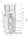
- An electric motor 1, as in Fig.1 includes a motor housing 8, in which a stator 5 and arranged on a motor shaft 7 rotor 6 is provided.
- the motor shaft 7 is rotatably mounted on both sides of the electric motor 1, wherein a bearing (shown here) comprises the bearing assembly according to the invention.
- the other bearing can be, for example, a simple floating bearing with a ball roller bearing.
- an output flange 10 is provided in the embodiment shown, to which the load to be driven, for example, a drive spindle of a spindle nut drive a press, is attached.
- the bearing assembly according to the invention consists of two spherical roller bearings 2, 3, which are arranged on a bearing ring 9, which has a radial shoulder 11.
- the inner bearing shells 12, 13 of the spherical roller bearings 2, 3 are arranged non-positively on the bearing ring 9, wherein the bearing inner shells 12, 13 facing each other and are arranged axially adjacent to the shoulder 11.
- the shoulder 11 is at least so high that caused by the contact surface pressure between inner bearing shells 12, 13 and shoulder 11 corresponds to the acceptable range for the particular application and also the bearing specification.
- the radial shoulder 11 is made as high as the radial height of the bearing inner shells 12, 13, so that they can be supported axially over the entire radial height of the shoulder 11.
- the adhesion is preferably carried out by a suitable interference fit, wherein the bearing inner shells 12, 13 can be shrunk onto the bearing ring 9.
- the interference fit must at least be designed so that the Lagerlosbrechmomente, typically in the range of about 90 Nm, can be transmitted.
- the bearing ring 9 is screwed to the front side with the motor shaft 7 and the output flange 10 and thereby clamped axially.
- bores are provided in the output flange 10 and in the bearing ring 9 distributed over the circumference, are inserted through the screws 14, which are screwed into internal threads 15 on the motor shaft 7.
- the bearing edges 21, 22 of the bearing inner shells 12, 13 are axially spaced from the output flange 10 and arranged by the motor shaft 7, so that the bearing inner shells 12, 13 are not clamped by the frontal screw.
- the bearing outer shells 16, 17 are in the bearing housing 4, which is part of the motor housing 8, arranged and held.
- the second bearing outer shell 17 is axially displaceable, for example by a suitable clearance, and is located axially against an axially acting spring 19, which is supported on a fixed biasing ring 20, wherein the biasing ring 20 fixed, but detachable with the bearing housing 4 and the motor housing 8 is connected.
- the biasing ring 20 has a first recess 23 for receiving the spring 19 and a second recess 24 for receiving a sealing element 25 which bears against the motor shaft 7 for sealing between the lubricated bearing and the rotor space.
- the biasing ring 20 is screwed here, for example, with the bearing housing 4, as in Fig. 1 indicated.
- the spring 19 is used to bias the bearing assembly by the bearing assembly is pressed with the axially displaceable motor shaft 7 against the radial shoulder 18 of the bearing housing, and the thermal compensation by recording the operational thermal expansion of the spherical roller bearings 2, 3.
- the bearing preload is kept constant with temperature change.
- the bearing inner shells 12, 13 are to be arranged on the bearing ring 9, e.g. shrink, and then the first outer bearing shell 16, the bearing ring 9 and the second bearing outer shell 17 can be inserted in the bearing housing 4 in turn. Thereafter, the spring 19 can be arranged in the biasing ring 20.
- the remaining motor housing 8 with motor shaft 7 is then pushed in and screwed axially to the output flange 10.
- the bearing assembly can therefore also be easily pre-assembled and connected to the motor housing 8.
Landscapes
- Engineering & Computer Science (AREA)
- General Engineering & Computer Science (AREA)
- Mechanical Engineering (AREA)
- Power Engineering (AREA)
- Support Of The Bearing (AREA)
Abstract
Description
- Lageranordnung mit zwei Pendelrollenlagern zum Lagern einer Motorwelle in einem Motorgehäuse.
- Bei Elektromotoranwendungen bei denen neben den üblichen Drehmomenten auch hohe Axialkräfte auftreten, z.B. bei Spindelmutterantrieben für Pressen, werden abtriebsseitig im Motor häufig Pendelrollenlager zur Lagerung der Motorwelle eingesetzt. Dabei werden zwei Pendelrollenlager axial hintereinander angeordnet, wobei die Lagerinnenschalen zueinander gerichtet angeordnet sind und mittels Schrauben gegeneinander verpresst werden. Dazu wird z.B. ein Abtriebsflansch, an dem die Last befestigt wird, stirnseitig mit der Abtriebswelle und an der Lageraußenschale anliegend verschraubt, womit gleichzeitig die beiden Pendelrollenlager verspannt werden. Dabei treten in der Praxis allerdings erhebliche Probleme auf. Einerseits werden die Lagerkanten der Lagerinnenschalen durch die hohen Axialkräfte (Last, Schraubverspannung) einer hohen Flächenpressung ausgesetzt. Aus geometrischen Gründen (genormte Lagerdimensionen) ist die verfügbare Lagerkante allerdings beschränkt und durch die Lagerbaureihe vorgegeben, sodass die mögliche Axialbelastung dadurch beschränkt wird. Aufgrund der geringen verfügbaren Fläche zur axialen Abstützung wirkt sich die hohe Schraubenvorspannung nachteilig aus, was dieses Problem noch verschärft. Aufgrund der notwendigen hohen Lagervorspannung erhöht sich darüber hinaus in nachteiliger Weise auch das Lagerlosbrechmoment der Lagerinnenringe (jenes Drehmoment, das benötigt wird, um das Lager vom Stillstand zu drehen). Die Lagerlosbrechmomente erhöhen sich auch mit steigender Temperatur (Materialausdehnung), was sich ebenfalls nachteilig auf den Anwendungsfall auswirkt. Diese Probleme führten in der Praxis zu häufigen Schraubenabrissen und damit verbundenen Beschädigungen und Stillstandszeiten des Antriebs. Andererseits kommt es durch das Anliegen des Abtriebsflansches an der Lageraußenschale und dem durch diese Anordnung bedingten axialen Spalt zwischen Abtriebsring und Welle auch zu einem Verkippen des Abtriebsflansches, was zu unerlaubten Schraubenbelastungen unter dem Schraubenkopf führt.
- In einem Drehgelenk gemäß der
US 6 637 969 B2 sind die Lageraußenschalen einander zugewandt in einer Außenhülse angeordnet und axial durch eine Schulter, an der beide Lageraußenschalen anliegen, getrennt. Die Lagerinnenschalen sind an einer Welle angeordnet. In einem solchen Drehlager sind sowohl Außenhülse, als auch Welle drehbar, wodurch die Lageranordnung einfach von beiden Seiten montiert werden kann. Eine solche Anordnung wäre in einem Elektromotor aber schwierig, da das Motorgehäuse starr angeordnet ist und die Montage der Pendelrollenlager nur sehr schwierig möglich wäre. Dazu müsste ein Lager umständlich durch das Motorgehäuse hindurch von der anderen Seite montiert werden. - Es ist nun eine Aufgabe der gegenständlichen Erfindung, eine Lageranordnung anzugeben, die einer hohen Axialbelastung ausgesetzt werden kann, die einfach montiert werden kann und die ein Verkippen des Abtriebsflansches reduziert.
- Diese Aufgabe wird erfindungsgemäß dadurch gelöst, dass ein Lagerring mit einer radialen Schulter vorgesehen ist und die Lagerinnenschalen der Pendelrollenlager einander zugewandt und axial an der radialen Schuler anliegend auf dem Lagerring angeordnet sind und dass der Lagerring im betriebsgemäßen Einsatz der Lageranordnung axial mit der Motorwelle verspannt ist, wobei sich eine Lageraußenschale eines Pendelrollenlagers axial gegen eine radiale Schulter des Motorgehäuses und sich die andere Lageraußenschale axiale gegen eine ortsfest angeordnete Feder abstützt. Durch diese Anordnung wird erreicht, dass die Lagerinnenschalen axial nicht mehr an den Lagerkanten der Lagerinnenschalen abgestützt werden, sondern an der freien Stirnseite der Lagerinnenschalen und damit erheblich mehr axiale Abstützfläche zur Verfügung steht. Damit kann die Flächenpressung reduziert werden bzw. können höhere axiale Lasten aufgenommen werden. Die axiale Kraft wird erfindungsgemäß über den Lagerring übertragen, der mit Abtriebsflansch und Motorwelle stirnseitig verspannt ist, womit ein Verkippen des Abtriebsflansches verringert wird. Darüber hinaus kann eine solche Anordnung einfach montiert werden.
- Um die Losbrechmomente sicher übertragen zu können, sind die Lagerinnenschalen vorteilhaft auf den Lagerring aufgeschrumpft, um eine einfache kraftschlüssige Verbindung herzustellen.
- Durch die feste Anordnung der ersten Lageraußenschale und axial verschiebbare Anordnung der zweiten Lageraußenschale wird auf einfache Weise erreicht, dass die Lagervorspannung durch die Feder auch bei Temperaturänderungen im Wesentlichen konstant gehalten wird.
- Für einen konstruktiv einfachen Aufbau der Lageranordnung, die eine einfache Montage derselben ermöglicht, ist vorteilhaft ein lösbar mit dem Motorgehäuse verbundener Vorspannring vorgesehen, der eine erste Ausnehmung hat, in der die Feder angeordnet wird.
- Wenn im Vorspannring eine zweite Ausnehmung vorgesehen ist, in der ein Dichtelement angeordnet wird, kann durch die Lageranordnung gleichzeitig eine Abdichtung zwischen dem geschmierten Lagerraum und dem Rotorraum des Motors hergestellt werden.
- Bevorzugt wird der Lagerring im Elektromotor durch den Abtriebsflansch mittels einer Verschraubung axial mit der Motorwelle verspannt, was die Montage der Lageranordnung vereinfacht.
- Die gegenständliche Erfindung wird nachfolgend unter Bezugnahme auf die schematische, ein vorteilhaftes Ausführungsbeispiel zeigende
Figur 1 näher erläutert. Dabei zeigt -
Fig.1 einen Ausschnitt eines Elektromotors mit der erfindungsgemäßen Lageranordnung. - Ein Elektromotor 1, wie in
Fig.1 angedeutet, umfasst bekanntermaßen ein Motorgehäuse 8, in dem ein Stator 5 und ein auf einer Motorwelle 7 angeordneter Rotor 6 vorgesehen ist. Die Motorwelle 7 ist an beiden Seiten des Elektromotors 1 drehbar gelagert, wobei eine Lagerung (die hier dargestellte) die erfindungsgemäße Lageranordnung umfasst. Die andere Lagerung kann z.B. ein einfaches Loslager mit einem Kugelrollenlager sein. Abtriebsseitig ist im gezeigten Ausführungsbeispiel ein Abtriebsflansch 10 vorgesehen, an dem die anzutreibende Last, z.B. eine Antriebsspindel eines Spindelmutterantriebs einer Presse, befestigt wird. - Die erfindungsgemäße Lageranordnung besteht aus zwei Pendelrollenlagern 2, 3, die auf einem Lagerring 9 angeordnet sind, der eine radiale Schulter 11 aufweist. Die Lagerinnenschalen 12, 13 der Pendelrollenlager 2, 3 sind am Lagerring 9 kraftschlüssig angeordnet, wobei die Lagerinnenschalen 12, 13 einander zugewandt und axial an der Schulter 11 anliegend angeordnet sind. Die Schulter 11 ist dabei zumindest so hoch, dass die durch die Berührung hervorgerufene Flächenpressung zwischen Lagerinnenschalen 12, 13 und Schulter 11 im für den jeweiligen Anwendungsfall akzeptablen Bereich und auch der Lagerspezifikation entspricht. Bevorzugt wird die radiale Schulter 11 so hoch wie die radiale Höhe der Lagerinnenschalen 12, 13 gemacht, damit sich diese über deren gesamte radialen Höhe axial an der Schulter 11 abstützen können. Der Kraftschluss erfolgt vorzugweise durch eine geeignete Presspassung, wobei die Lagerinnenschalen 12, 13 auf den Lagerring 9 aufgeschrumpft werden können. Die Presspassung muss dabei zumindest so ausgelegt sein, dass die Lagerlosbrechmomente, typischerweise im Bereich von ca. 90Nm, übertragen werden können.
- Der Lagerring 9 wird stirnseitig mit der Motorwelle 7 und dem Abtriebsflansch 10 verschraubt und dadurch axial verspannt. Dazu sind im Abtriebsflansch 10 und im Lagerring 9 über den Umfang verteilt Bohrungen vorgesehen, durch die Schrauben 14 gesteckt werden, die in Innengewinden 15 an der Motorwelle 7 geschraubt werden. Die Lagerkanten 21, 22 der Lagerinnenschalen 12, 13 sind dabei axial beabstandet vom Abtriebsflansch 10 und von der Motorwelle 7 angeordnet, sodass die Lagerinnenschalen 12, 13 durch die stirnseitige Verschraubung nicht verspannt werden.
- Die Lageraußenschalen 16, 17 sind im Lagergehäuse 4, das Teil des Motorgehäuses 8 ist, angeordnet und gehalten. Die Lageraußenschale 16 des ersten Pendelrollenlagers 2, hier das axial außen liegende Lager, liegt dabei axial an einer Schulter 18 im Lagergehäuse 4 an und ist fest montiert, z.B. durch eine geeignete Press- oder Übergangspassung. Die zweite Lageraußenschale 17 ist axial verschiebbar, z.B. durch eine geeignete Spielpassung, und liegt axial an einer axial wirkenden Feder 19 an, die sich an einem feststehenden Vorspannring 20 abstützt, wobei der Vorspannring 20 ortsfest, aber lösbar mit dem Lagergehäuses 4 bzw. dem Motorgehäuse 8 verbunden ist. Der Vorspannring 20 hat eine erste Ausnehmung 23 zur Aufnahme der Feder 19 und eine zweite Ausnehmung 24 zur Aufnahme eines Dichtelements 25 aufweist, das zur Abdichtung zwischen der geschmierten Lagerung und dem Rotorraum an der Motorwelle 7 anliegt. Der Vorspannring 20 ist hier z.B. mit dem Lagergehäuse 4 verschraubt, wie in
Fig. 1 angedeutet. - Die Feder 19 dient zum Vorspannen der Lageranordnung, indem die Lageranordnung mit der axial verschiebbaren Motorwelle 7 gegen die radiale Schulter 18 des Lagergehäuses gedrückt wird, und der thermischen Kompensation durch Aufnahme der betriebsbedingten thermischen Ausdehnung der Pendelrollenlager 2, 3. Durch die axial verschiebbare Lageraußenschale 17 wird die Lagervorspannung bei Temperaturänderung konstant gehalten.
- Zur Montage der Lageranordnung sind die Lagerinnenschalen 12, 13 auf dem Lagerring 9 anzuordnen, z.B. aufzuschrumpfen, und danach kann die erste Lageraußenschale 16, der Lagerring 9 und die zweite Lageraußenschale 17 im Lagergehäuse 4 der Reihe nach eingefügt werden. Danach kann die Feder 19 im Vorspannring 20 angeordnet werden. Das restliche Motorgehäuse 8 mit Motorwelle 7 wird dann hineingeschoben und axial mit dem Abtriebsflansch 10 verschraubt. Die Lageranordnung kann daher auch einfach vormontiert werden und anschließen mit dem Motorgehäuse 8 verbunden werden.
Claims (7)
- Lageranordnung mit zwei Pendelrollenlagern (2, 3) zum Lagern einer Motorwelle (7) in einem Motorgehäuse (8), dadurch gekennzeichnet, dass ein Lagerring (9) mit einer radialen Schulter (11) vorgesehen ist und die Lagerinnenschalen (12, 13) der Pendelrollenlager (2, 3) einander zugewandt und axial an der radialen Schuler (11) anliegend auf dem Lagerring (9) angeordnet sind und dass der Lagerring (9) im betriebsgemäßen Einsatz der Lageranordnung axial mit der Motorwelle (7) verspannt ist, wobei sich eine erste Lageraußenschale (16) eines Pendelrollenlagers (2) axial gegen eine radiale Schulter (18) des Motorgehäuses (8) und sich die zweite Lageraußenschale (17) axial gegen eine ortsfest angeordnete Feder (19) abstützt.
- Lageranordnung nach Anspruch 1, dadurch gekennzeichnet, dass die Lagerinnenschalen (12, 13) auf den Lagerring (9) aufgeschrumpft sind.
- Lageranordnung nach Anspruch 1 oder 2, dadurch gekennzeichnet, dass die erste Lageraußenschale (16) fest und die zweite Lageraußenschale (17) axial verschiebbar im Motorgehäuse (8) angeordnet ist.
- Lageranordnung nach einem der Ansprüche 1 bis 3, dadurch gekennzeichnet, dass ein Vorspannring (20) mit einer ersten Ausnehmung (23) vorgesehen ist, in der die Feder (19) angeordnet ist und der Vorspannring (20) lösbar mit dem Motorgehäuse (8) verbunden ist.
- Lageranordnung nach Anspruch 4, dadurch gekennzeichnet, dass im Vorspannring (20) eine zweite Ausnehmung (24) vorgesehen ist, in der ein Dichtelement (25) angeordnet ist.
- Elektromotor mit einer Motorwelle (7), die an einer Seite mit einer Lageranordnung nach einem der Ansprüche 1 bis 5 gelagert ist.
- Elektromotor nach Anspruch 6, dadurch gekennzeichnet, dass ein Abtriebsflansch (10) vorgesehen ist, der den Lagerring (9) mittels einer Verschraubung axial mit der Motorwelle (7) verspannt.
Applications Claiming Priority (1)
| Application Number | Priority Date | Filing Date | Title |
|---|---|---|---|
| AT0036210A AT509333B1 (de) | 2010-03-08 | 2010-03-08 | Lagerandordnung mit zwei pendelrollenlagern |
Publications (3)
| Publication Number | Publication Date |
|---|---|
| EP2369191A2 true EP2369191A2 (de) | 2011-09-28 |
| EP2369191A3 EP2369191A3 (de) | 2012-09-19 |
| EP2369191B1 EP2369191B1 (de) | 2013-08-07 |
Family
ID=44144840
Family Applications (1)
| Application Number | Title | Priority Date | Filing Date |
|---|---|---|---|
| EP11157145.1A Not-in-force EP2369191B1 (de) | 2010-03-08 | 2011-03-07 | Lageranordnung mit zwei Pendelrollenlagern |
Country Status (3)
| Country | Link |
|---|---|
| EP (1) | EP2369191B1 (de) |
| AT (1) | AT509333B1 (de) |
| ES (1) | ES2433660T3 (de) |
Cited By (3)
| Publication number | Priority date | Publication date | Assignee | Title |
|---|---|---|---|---|
| CN107806473A (zh) * | 2016-09-08 | 2018-03-16 | 上海西门子医疗器械有限公司 | 具有压板的轴承及其装配方法 |
| CN107830065A (zh) * | 2017-12-04 | 2018-03-23 | 洛阳理工学院 | 成对推力球轴承预紧装置 |
| EP3845482B1 (de) | 2019-12-30 | 2023-08-30 | STILL GmbH | Fahrerloses transportfahrzeug mit einer mittels eines gewindespindelantriebs anhebbaren und absenkbaren lastaufnahmeplattform |
Families Citing this family (4)
| Publication number | Priority date | Publication date | Assignee | Title |
|---|---|---|---|---|
| KR102171453B1 (ko) * | 2019-06-21 | 2020-10-29 | 엘지전자 주식회사 | 모터 어셈블리 및 그 제조 방법 |
| CN111795077B (zh) * | 2020-06-09 | 2022-02-11 | 江苏理工学院 | 一种轴承预紧装置 |
| CN113659759B (zh) * | 2021-08-19 | 2022-11-04 | 天津飞旋科技股份有限公司 | 电机 |
| CN115750589B (zh) * | 2022-11-16 | 2024-10-18 | 太仓市凯福士机械有限公司 | 一种用于汽车轮毂的可调整式轴承 |
Citations (1)
| Publication number | Priority date | Publication date | Assignee | Title |
|---|---|---|---|---|
| US6637969B2 (en) | 2001-08-30 | 2003-10-28 | Robbins Tools, Inc. | Swivel |
Family Cites Families (6)
| Publication number | Priority date | Publication date | Assignee | Title |
|---|---|---|---|---|
| US2986436A (en) * | 1957-06-24 | 1961-05-30 | Shinko Electric Co Ltd | Bearing structure for rotor of high speed motor |
| SE422348B (sv) * | 1977-10-24 | 1982-03-01 | Stal Refrigeration Ab | Anordning vid en kompressor av rotationstyp for att fixera en rotoraxel i axiell led |
| DE4411760A1 (de) * | 1994-04-06 | 1995-10-12 | Rostock Dieselmotoren | Einrichtung zur Weiterleitung von Axialkräften in Motor-Getriebe-Anlagen |
| SE9704203L (sv) * | 1997-11-13 | 1998-11-09 | Skf Ab | Propellertrycklager |
| DE10136201A1 (de) * | 2001-07-25 | 2003-02-20 | Kloeckner Humboldt Wedag | Rollenpresse mit vormontiertem Axiallager |
| CN102138015A (zh) * | 2008-08-27 | 2011-07-27 | Skf公司 | 用于船舱推进系统的轴承 |
-
2010
- 2010-03-08 AT AT0036210A patent/AT509333B1/de not_active IP Right Cessation
-
2011
- 2011-03-07 EP EP11157145.1A patent/EP2369191B1/de not_active Not-in-force
- 2011-03-07 ES ES11157145T patent/ES2433660T3/es active Active
Patent Citations (1)
| Publication number | Priority date | Publication date | Assignee | Title |
|---|---|---|---|---|
| US6637969B2 (en) | 2001-08-30 | 2003-10-28 | Robbins Tools, Inc. | Swivel |
Cited By (3)
| Publication number | Priority date | Publication date | Assignee | Title |
|---|---|---|---|---|
| CN107806473A (zh) * | 2016-09-08 | 2018-03-16 | 上海西门子医疗器械有限公司 | 具有压板的轴承及其装配方法 |
| CN107830065A (zh) * | 2017-12-04 | 2018-03-23 | 洛阳理工学院 | 成对推力球轴承预紧装置 |
| EP3845482B1 (de) | 2019-12-30 | 2023-08-30 | STILL GmbH | Fahrerloses transportfahrzeug mit einer mittels eines gewindespindelantriebs anhebbaren und absenkbaren lastaufnahmeplattform |
Also Published As
| Publication number | Publication date |
|---|---|
| AT509333A4 (de) | 2011-08-15 |
| ES2433660T3 (es) | 2013-12-12 |
| AT509333B1 (de) | 2011-08-15 |
| EP2369191B1 (de) | 2013-08-07 |
| EP2369191A3 (de) | 2012-09-19 |
Similar Documents
| Publication | Publication Date | Title |
|---|---|---|
| EP2369191B1 (de) | Lageranordnung mit zwei Pendelrollenlagern | |
| EP2652347B1 (de) | Elektrische maschine, insbesondere eines pumpenaggregates | |
| DE102013208980B4 (de) | Retarderwelle | |
| EP2056987B1 (de) | Fräswerkzeug, insbesondere einer handfräsmaschine zum fräsen von fasen | |
| EP3135929A1 (de) | Wellenlagerung | |
| EP3456467A2 (de) | Motorspindel für eine werkzeugmaschine mit integrierter kühlung und drehdurchführungsmodul | |
| DE102006019873B3 (de) | Fanglager für eine elektrische Maschine sowie elektrische Maschine mit zumindest einem derartigen Fanglager | |
| EP2850719A1 (de) | Statoranordnung für eine elektrische maschine | |
| EP1596488B1 (de) | Antriebsmotor mit integrierten Wellenverbindungselementen | |
| EP2726749B1 (de) | Kompakte axial-radial-lagerung | |
| DE102009016187B4 (de) | Lager für eine Vorrichtung zur Erzeugung eines Schwenkmoments | |
| DE102008051613B4 (de) | Fräskopf | |
| EP3224932B1 (de) | Linearantrieb, aufweisend einen von einem elektromotor über eine kupplung antreibbaren spindeltrieb | |
| EP3938670B1 (de) | Rotorlagerung einer windkraftanlage | |
| DE102024210942A1 (de) | Hydrostatische Rotationsmaschine mit optimierter Bremse | |
| DE3017722C2 (de) | Brechbolzen-Drehmomentbegrenzungseinrichtung für zwei relativ zueinander drehbare Bauelemente | |
| DE102020117453A1 (de) | Rotor einer elektrischen Rotationsmaschine, Verfahren zur Herstellung des Rotors und elektrische Rotationsmaschine | |
| WO2008034417A2 (de) | Lagereinheit zur axialen wellenpositionierung | |
| DE102006029679A1 (de) | Gleitdrehverbindung | |
| DE10332010B4 (de) | Drehdurchführung | |
| DE102015008716A1 (de) | Antriebsanordnung für eine Schwenkbrücke | |
| EP1749929B1 (de) | Vorrichtung zur Herstellung und/oder Behandlung einer Materialbahn, insbesondere Papier- oder Kartonbahn | |
| DE102004024080B4 (de) | Bürstendichtung | |
| EP2769108A1 (de) | Friktionsbremse, fanglager mit friktionsbremse und verfahren zum betreiben eines magnetlagers | |
| US10900515B2 (en) | Yaw bearing arrangement |
Legal Events
| Date | Code | Title | Description |
|---|---|---|---|
| PUAI | Public reference made under article 153(3) epc to a published international application that has entered the european phase |
Free format text: ORIGINAL CODE: 0009012 |
|
| AK | Designated contracting states |
Kind code of ref document: A2 Designated state(s): AL AT BE BG CH CY CZ DE DK EE ES FI FR GB GR HR HU IE IS IT LI LT LU LV MC MK MT NL NO PL PT RO RS SE SI SK SM TR |
|
| AX | Request for extension of the european patent |
Extension state: BA ME |
|
| PUAL | Search report despatched |
Free format text: ORIGINAL CODE: 0009013 |
|
| AK | Designated contracting states |
Kind code of ref document: A3 Designated state(s): AL AT BE BG CH CY CZ DE DK EE ES FI FR GB GR HR HU IE IS IT LI LT LU LV MC MK MT NL NO PL PT RO RS SE SI SK SM TR |
|
| AX | Request for extension of the european patent |
Extension state: BA ME |
|
| RIC1 | Information provided on ipc code assigned before grant |
Ipc: F16C 19/54 20060101AFI20120810BHEP Ipc: F16C 23/08 20060101ALI20120810BHEP Ipc: H02K 5/16 20060101ALI20120810BHEP Ipc: H02K 7/08 20060101ALI20120810BHEP Ipc: F16C 27/08 20060101ALI20120810BHEP Ipc: F16C 25/08 20060101ALI20120810BHEP |
|
| 17P | Request for examination filed |
Effective date: 20121219 |
|
| GRAP | Despatch of communication of intention to grant a patent |
Free format text: ORIGINAL CODE: EPIDOSNIGR1 |
|
| RIC1 | Information provided on ipc code assigned before grant |
Ipc: H02K 5/16 20060101ALI20130214BHEP Ipc: H02K 7/08 20060101ALI20130214BHEP Ipc: F16C 25/08 20060101ALI20130214BHEP Ipc: F16C 27/08 20060101ALI20130214BHEP Ipc: F16C 19/54 20060101AFI20130214BHEP Ipc: H02K 5/173 20060101ALI20130214BHEP Ipc: F16C 23/08 20060101ALI20130214BHEP |
|
| GRAS | Grant fee paid |
Free format text: ORIGINAL CODE: EPIDOSNIGR3 |
|
| GRAA | (expected) grant |
Free format text: ORIGINAL CODE: 0009210 |
|
| AK | Designated contracting states |
Kind code of ref document: B1 Designated state(s): AL AT BE BG CH CY CZ DE DK EE ES FI FR GB GR HR HU IE IS IT LI LT LU LV MC MK MT NL NO PL PT RO RS SE SI SK SM TR |
|
| REG | Reference to a national code |
Ref country code: GB Ref legal event code: FG4D Free format text: NOT ENGLISH |
|
| REG | Reference to a national code |
Ref country code: AT Ref legal event code: REF Ref document number: 625896 Country of ref document: AT Kind code of ref document: T Effective date: 20130815 Ref country code: CH Ref legal event code: EP |
|
| REG | Reference to a national code |
Ref country code: IE Ref legal event code: FG4D Free format text: LANGUAGE OF EP DOCUMENT: GERMAN |
|
| REG | Reference to a national code |
Ref country code: DE Ref legal event code: R096 Ref document number: 502011001151 Country of ref document: DE Effective date: 20131002 |
|
| REG | Reference to a national code |
Ref country code: CH Ref legal event code: NV Representative=s name: ISLER AND PEDRAZZINI AG, CH |
|
| REG | Reference to a national code |
Ref country code: ES Ref legal event code: FG2A Ref document number: 2433660 Country of ref document: ES Kind code of ref document: T3 Effective date: 20131212 |
|
| REG | Reference to a national code |
Ref country code: NL Ref legal event code: VDEP Effective date: 20130807 |
|
| REG | Reference to a national code |
Ref country code: LT Ref legal event code: MG4D |
|
| PG25 | Lapsed in a contracting state [announced via postgrant information from national office to epo] |
Ref country code: NO Free format text: LAPSE BECAUSE OF FAILURE TO SUBMIT A TRANSLATION OF THE DESCRIPTION OR TO PAY THE FEE WITHIN THE PRESCRIBED TIME-LIMIT Effective date: 20131107 Ref country code: SE Free format text: LAPSE BECAUSE OF FAILURE TO SUBMIT A TRANSLATION OF THE DESCRIPTION OR TO PAY THE FEE WITHIN THE PRESCRIBED TIME-LIMIT Effective date: 20130807 Ref country code: CY Free format text: LAPSE BECAUSE OF FAILURE TO SUBMIT A TRANSLATION OF THE DESCRIPTION OR TO PAY THE FEE WITHIN THE PRESCRIBED TIME-LIMIT Effective date: 20130619 Ref country code: IS Free format text: LAPSE BECAUSE OF FAILURE TO SUBMIT A TRANSLATION OF THE DESCRIPTION OR TO PAY THE FEE WITHIN THE PRESCRIBED TIME-LIMIT Effective date: 20131207 Ref country code: LT Free format text: LAPSE BECAUSE OF FAILURE TO SUBMIT A TRANSLATION OF THE DESCRIPTION OR TO PAY THE FEE WITHIN THE PRESCRIBED TIME-LIMIT Effective date: 20130807 Ref country code: HR Free format text: LAPSE BECAUSE OF FAILURE TO SUBMIT A TRANSLATION OF THE DESCRIPTION OR TO PAY THE FEE WITHIN THE PRESCRIBED TIME-LIMIT Effective date: 20130807 Ref country code: PT Free format text: LAPSE BECAUSE OF FAILURE TO SUBMIT A TRANSLATION OF THE DESCRIPTION OR TO PAY THE FEE WITHIN THE PRESCRIBED TIME-LIMIT Effective date: 20131209 |
|
| PG25 | Lapsed in a contracting state [announced via postgrant information from national office to epo] |
Ref country code: PL Free format text: LAPSE BECAUSE OF FAILURE TO SUBMIT A TRANSLATION OF THE DESCRIPTION OR TO PAY THE FEE WITHIN THE PRESCRIBED TIME-LIMIT Effective date: 20130807 Ref country code: SI Free format text: LAPSE BECAUSE OF FAILURE TO SUBMIT A TRANSLATION OF THE DESCRIPTION OR TO PAY THE FEE WITHIN THE PRESCRIBED TIME-LIMIT Effective date: 20130807 Ref country code: LV Free format text: LAPSE BECAUSE OF FAILURE TO SUBMIT A TRANSLATION OF THE DESCRIPTION OR TO PAY THE FEE WITHIN THE PRESCRIBED TIME-LIMIT Effective date: 20130807 Ref country code: NL Free format text: LAPSE BECAUSE OF FAILURE TO SUBMIT A TRANSLATION OF THE DESCRIPTION OR TO PAY THE FEE WITHIN THE PRESCRIBED TIME-LIMIT Effective date: 20130807 Ref country code: GR Free format text: LAPSE BECAUSE OF FAILURE TO SUBMIT A TRANSLATION OF THE DESCRIPTION OR TO PAY THE FEE WITHIN THE PRESCRIBED TIME-LIMIT Effective date: 20131108 Ref country code: FI Free format text: LAPSE BECAUSE OF FAILURE TO SUBMIT A TRANSLATION OF THE DESCRIPTION OR TO PAY THE FEE WITHIN THE PRESCRIBED TIME-LIMIT Effective date: 20130807 |
|
| PG25 | Lapsed in a contracting state [announced via postgrant information from national office to epo] |
Ref country code: CY Free format text: LAPSE BECAUSE OF FAILURE TO SUBMIT A TRANSLATION OF THE DESCRIPTION OR TO PAY THE FEE WITHIN THE PRESCRIBED TIME-LIMIT Effective date: 20130807 |
|
| PG25 | Lapsed in a contracting state [announced via postgrant information from national office to epo] |
Ref country code: EE Free format text: LAPSE BECAUSE OF FAILURE TO SUBMIT A TRANSLATION OF THE DESCRIPTION OR TO PAY THE FEE WITHIN THE PRESCRIBED TIME-LIMIT Effective date: 20130807 Ref country code: CZ Free format text: LAPSE BECAUSE OF FAILURE TO SUBMIT A TRANSLATION OF THE DESCRIPTION OR TO PAY THE FEE WITHIN THE PRESCRIBED TIME-LIMIT Effective date: 20130807 Ref country code: DK Free format text: LAPSE BECAUSE OF FAILURE TO SUBMIT A TRANSLATION OF THE DESCRIPTION OR TO PAY THE FEE WITHIN THE PRESCRIBED TIME-LIMIT Effective date: 20130807 Ref country code: RO Free format text: LAPSE BECAUSE OF FAILURE TO SUBMIT A TRANSLATION OF THE DESCRIPTION OR TO PAY THE FEE WITHIN THE PRESCRIBED TIME-LIMIT Effective date: 20130807 Ref country code: SK Free format text: LAPSE BECAUSE OF FAILURE TO SUBMIT A TRANSLATION OF THE DESCRIPTION OR TO PAY THE FEE WITHIN THE PRESCRIBED TIME-LIMIT Effective date: 20130807 |
|
| PLBE | No opposition filed within time limit |
Free format text: ORIGINAL CODE: 0009261 |
|
| STAA | Information on the status of an ep patent application or granted ep patent |
Free format text: STATUS: NO OPPOSITION FILED WITHIN TIME LIMIT |
|
| 26N | No opposition filed |
Effective date: 20140508 |
|
| REG | Reference to a national code |
Ref country code: DE Ref legal event code: R097 Ref document number: 502011001151 Country of ref document: DE Effective date: 20140508 |
|
| PG25 | Lapsed in a contracting state [announced via postgrant information from national office to epo] |
Ref country code: LU Free format text: LAPSE BECAUSE OF FAILURE TO SUBMIT A TRANSLATION OF THE DESCRIPTION OR TO PAY THE FEE WITHIN THE PRESCRIBED TIME-LIMIT Effective date: 20140307 |
|
| REG | Reference to a national code |
Ref country code: IE Ref legal event code: MM4A |
|
| PG25 | Lapsed in a contracting state [announced via postgrant information from national office to epo] |
Ref country code: IE Free format text: LAPSE BECAUSE OF NON-PAYMENT OF DUE FEES Effective date: 20140307 |
|
| PG25 | Lapsed in a contracting state [announced via postgrant information from national office to epo] |
Ref country code: MT Free format text: LAPSE BECAUSE OF FAILURE TO SUBMIT A TRANSLATION OF THE DESCRIPTION OR TO PAY THE FEE WITHIN THE PRESCRIBED TIME-LIMIT Effective date: 20130807 |
|
| REG | Reference to a national code |
Ref country code: FR Ref legal event code: PLFP Year of fee payment: 6 |
|
| PG25 | Lapsed in a contracting state [announced via postgrant information from national office to epo] |
Ref country code: SM Free format text: LAPSE BECAUSE OF FAILURE TO SUBMIT A TRANSLATION OF THE DESCRIPTION OR TO PAY THE FEE WITHIN THE PRESCRIBED TIME-LIMIT Effective date: 20130807 |
|
| PG25 | Lapsed in a contracting state [announced via postgrant information from national office to epo] |
Ref country code: MC Free format text: LAPSE BECAUSE OF FAILURE TO SUBMIT A TRANSLATION OF THE DESCRIPTION OR TO PAY THE FEE WITHIN THE PRESCRIBED TIME-LIMIT Effective date: 20130807 |
|
| PG25 | Lapsed in a contracting state [announced via postgrant information from national office to epo] |
Ref country code: BG Free format text: LAPSE BECAUSE OF FAILURE TO SUBMIT A TRANSLATION OF THE DESCRIPTION OR TO PAY THE FEE WITHIN THE PRESCRIBED TIME-LIMIT Effective date: 20130807 Ref country code: RS Free format text: LAPSE BECAUSE OF FAILURE TO SUBMIT A TRANSLATION OF THE DESCRIPTION OR TO PAY THE FEE WITHIN THE PRESCRIBED TIME-LIMIT Effective date: 20130807 |
|
| PG25 | Lapsed in a contracting state [announced via postgrant information from national office to epo] |
Ref country code: TR Free format text: LAPSE BECAUSE OF FAILURE TO SUBMIT A TRANSLATION OF THE DESCRIPTION OR TO PAY THE FEE WITHIN THE PRESCRIBED TIME-LIMIT Effective date: 20130807 Ref country code: HU Free format text: LAPSE BECAUSE OF FAILURE TO SUBMIT A TRANSLATION OF THE DESCRIPTION OR TO PAY THE FEE WITHIN THE PRESCRIBED TIME-LIMIT; INVALID AB INITIO Effective date: 20110307 Ref country code: BE Free format text: LAPSE BECAUSE OF FAILURE TO SUBMIT A TRANSLATION OF THE DESCRIPTION OR TO PAY THE FEE WITHIN THE PRESCRIBED TIME-LIMIT Effective date: 20140331 |
|
| REG | Reference to a national code |
Ref country code: FR Ref legal event code: PLFP Year of fee payment: 7 |
|
| REG | Reference to a national code |
Ref country code: AT Ref legal event code: HC Ref document number: 625896 Country of ref document: AT Kind code of ref document: T Owner name: B&R INDUSTRIAL AUTOMATION GMBH, AT Effective date: 20180205 |
|
| REG | Reference to a national code |
Ref country code: FR Ref legal event code: PLFP Year of fee payment: 8 |
|
| PGFP | Annual fee paid to national office [announced via postgrant information from national office to epo] |
Ref country code: DE Payment date: 20180322 Year of fee payment: 8 Ref country code: GB Payment date: 20180321 Year of fee payment: 8 Ref country code: CH Payment date: 20180321 Year of fee payment: 8 |
|
| PGFP | Annual fee paid to national office [announced via postgrant information from national office to epo] |
Ref country code: AT Payment date: 20180322 Year of fee payment: 8 Ref country code: FR Payment date: 20180328 Year of fee payment: 8 |
|
| PG25 | Lapsed in a contracting state [announced via postgrant information from national office to epo] |
Ref country code: MK Free format text: LAPSE BECAUSE OF FAILURE TO SUBMIT A TRANSLATION OF THE DESCRIPTION OR TO PAY THE FEE WITHIN THE PRESCRIBED TIME-LIMIT Effective date: 20130807 |
|
| PGFP | Annual fee paid to national office [announced via postgrant information from national office to epo] |
Ref country code: ES Payment date: 20180430 Year of fee payment: 8 |
|
| PGFP | Annual fee paid to national office [announced via postgrant information from national office to epo] |
Ref country code: IT Payment date: 20180327 Year of fee payment: 8 |
|
| PG25 | Lapsed in a contracting state [announced via postgrant information from national office to epo] |
Ref country code: AL Free format text: LAPSE BECAUSE OF FAILURE TO SUBMIT A TRANSLATION OF THE DESCRIPTION OR TO PAY THE FEE WITHIN THE PRESCRIBED TIME-LIMIT Effective date: 20130807 |
|
| REG | Reference to a national code |
Ref country code: DE Ref legal event code: R119 Ref document number: 502011001151 Country of ref document: DE |
|
| REG | Reference to a national code |
Ref country code: CH Ref legal event code: PL |
|
| REG | Reference to a national code |
Ref country code: AT Ref legal event code: MM01 Ref document number: 625896 Country of ref document: AT Kind code of ref document: T Effective date: 20190307 |
|
| GBPC | Gb: european patent ceased through non-payment of renewal fee |
Effective date: 20190307 |
|
| PG25 | Lapsed in a contracting state [announced via postgrant information from national office to epo] |
Ref country code: AT Free format text: LAPSE BECAUSE OF NON-PAYMENT OF DUE FEES Effective date: 20190307 Ref country code: LI Free format text: LAPSE BECAUSE OF NON-PAYMENT OF DUE FEES Effective date: 20190331 Ref country code: DE Free format text: LAPSE BECAUSE OF NON-PAYMENT OF DUE FEES Effective date: 20191001 Ref country code: GB Free format text: LAPSE BECAUSE OF NON-PAYMENT OF DUE FEES Effective date: 20190307 Ref country code: CH Free format text: LAPSE BECAUSE OF NON-PAYMENT OF DUE FEES Effective date: 20190331 |
|
| PG25 | Lapsed in a contracting state [announced via postgrant information from national office to epo] |
Ref country code: FR Free format text: LAPSE BECAUSE OF NON-PAYMENT OF DUE FEES Effective date: 20190331 Ref country code: IT Free format text: LAPSE BECAUSE OF NON-PAYMENT OF DUE FEES Effective date: 20190307 |
|
| REG | Reference to a national code |
Ref country code: ES Ref legal event code: FD2A Effective date: 20200724 |
|
| PG25 | Lapsed in a contracting state [announced via postgrant information from national office to epo] |
Ref country code: ES Free format text: LAPSE BECAUSE OF NON-PAYMENT OF DUE FEES Effective date: 20190308 |