EP2369334B1 - System und Verfahren zur Schadensdiagnose - Google Patents
System und Verfahren zur Schadensdiagnose Download PDFInfo
- Publication number
- EP2369334B1 EP2369334B1 EP11157867.0A EP11157867A EP2369334B1 EP 2369334 B1 EP2369334 B1 EP 2369334B1 EP 11157867 A EP11157867 A EP 11157867A EP 2369334 B1 EP2369334 B1 EP 2369334B1
- Authority
- EP
- European Patent Office
- Prior art keywords
- mode
- lamb wave
- damage
- time
- oscillation
- Prior art date
- Legal status (The legal status is an assumption and is not a legal conclusion. Google has not performed a legal analysis and makes no representation as to the accuracy of the status listed.)
- Active
Links
Images









Classifications
-
- G—PHYSICS
- G01—MEASURING; TESTING
- G01N—INVESTIGATING OR ANALYSING MATERIALS BY DETERMINING THEIR CHEMICAL OR PHYSICAL PROPERTIES
- G01N29/00—Investigating or analysing materials by the use of ultrasonic, sonic or infrasonic waves; Visualisation of the interior of objects by transmitting ultrasonic or sonic waves through the object
- G01N29/04—Analysing solids
- G01N29/07—Analysing solids by measuring propagation velocity or propagation time of acoustic waves
-
- G—PHYSICS
- G01—MEASURING; TESTING
- G01N—INVESTIGATING OR ANALYSING MATERIALS BY DETERMINING THEIR CHEMICAL OR PHYSICAL PROPERTIES
- G01N29/00—Investigating or analysing materials by the use of ultrasonic, sonic or infrasonic waves; Visualisation of the interior of objects by transmitting ultrasonic or sonic waves through the object
- G01N29/44—Processing the detected response signal, e.g. electronic circuits specially adapted therefor
- G01N29/4409—Processing the detected response signal, e.g. electronic circuits specially adapted therefor by comparison
- G01N29/4436—Processing the detected response signal, e.g. electronic circuits specially adapted therefor by comparison with a reference signal
-
- G—PHYSICS
- G01—MEASURING; TESTING
- G01N—INVESTIGATING OR ANALYSING MATERIALS BY DETERMINING THEIR CHEMICAL OR PHYSICAL PROPERTIES
- G01N29/00—Investigating or analysing materials by the use of ultrasonic, sonic or infrasonic waves; Visualisation of the interior of objects by transmitting ultrasonic or sonic waves through the object
- G01N29/44—Processing the detected response signal, e.g. electronic circuits specially adapted therefor
- G01N29/46—Processing the detected response signal, e.g. electronic circuits specially adapted therefor by spectral analysis, e.g. Fourier analysis or wavelet analysis
-
- G—PHYSICS
- G01—MEASURING; TESTING
- G01N—INVESTIGATING OR ANALYSING MATERIALS BY DETERMINING THEIR CHEMICAL OR PHYSICAL PROPERTIES
- G01N2291/00—Indexing codes associated with group G01N29/00
- G01N2291/01—Indexing codes associated with the measuring variable
- G01N2291/011—Velocity or travel time
-
- G—PHYSICS
- G01—MEASURING; TESTING
- G01N—INVESTIGATING OR ANALYSING MATERIALS BY DETERMINING THEIR CHEMICAL OR PHYSICAL PROPERTIES
- G01N2291/00—Indexing codes associated with group G01N29/00
- G01N2291/02—Indexing codes associated with the analysed material
- G01N2291/028—Material parameters
- G01N2291/0289—Internal structure, e.g. defects, grain size, texture
-
- G—PHYSICS
- G01—MEASURING; TESTING
- G01N—INVESTIGATING OR ANALYSING MATERIALS BY DETERMINING THEIR CHEMICAL OR PHYSICAL PROPERTIES
- G01N2291/00—Indexing codes associated with group G01N29/00
- G01N2291/04—Wave modes and trajectories
- G01N2291/042—Wave modes
- G01N2291/0427—Flexural waves, plate waves, e.g. Lamb waves, tuning fork, cantilever
Definitions
- the present invention relates to a system and method for damage diagnosis that uses Lamb waves.
- the inventions disclosed in Japanese patent publication1 and 2 below use an optical fiber sensor having a grating section wherein piezo elements that are fixed and arranged at specified locations in a structural composite material, lead wires that transmit signals to the piezo elements, an optical fiber sensor attached to the structural composite material so that the composite material of the structural composite material is located between the optical fiber sensor and the piezo elements, the optical fiber sensor having a grating section to reflect light of a specified wavelength to a core section, a light source that shines light on the core section, and a characteristic detection unit that detects a characteristic of the reflected light from the grating section, and vibrating the material by the piezo elements, detects damage from the change in output from the characteristics detection unit.
- a spectrum analyzer that detects the frequency characteristic of reflected light from the grating section is used as the characteristic detection unit.
- a comparison is performed with detected data of a normal structural composite material that was acquired beforehand.
- a threshold value is set for the fluctuation value from when there is no oscillation of a specified frequency, and when the detected value is equal to or less than that threshold value, it may be determined that there is damage (paragraph 0032).
- two optical filters are provided in a spectrum analyzer. It is proposed that by outputting reflected light to an arithmetic processing unit via the two optical filters, the spectrum analyzer will detect a wavelength oscillation signal of the reflected light with high sensitivity. It is also proposed that the arithmetic processing unit will calculate a value (DI value) that corresponds to the scale of the damage of the test object based on the obtained wavelength oscillation signal. Seth S. Kessler et al. describe in "Damage detection in composite materials using Lamb wave methods", Smart Mater. Struct. 11 (2002), 267-278, IOP Publishing Ltd.
- US 2009/078049 A1 discloses the detection of features on or within an object by applying ultrasonic oscillation to the object so as to generate at least one mode of Lamb wave including a plurality of waves with different frequencies, detecting said Lamb wave mode from the object, and performing time-frequency transformation (Fast Fourier Transform) to the detected wave.
- Lamb waves As a method of damage detection technology, research is being performed regarding a method in which ultrasonic waves called Lamb waves are generated and detected, and the occurrence of damages is diagnosed based on the change in the detected waves.
- the Lamb wave is an ultrasonic wave that propagates through a thin plate, and propagates over a long distance with a relatively small amount of damping. Therefore, it is a form of ultrasonic wave propagation that is suitable to damage detection.
- Lamb waves have two characteristics; a multi-mode characteristic and velocity dispersion characteristic (frequency dependence), and depending on the plate thickness and frequency, there are plurality of modes having different speeds. Due to these complex characteristics, conventionally, damage detection was performed by using only information about a specific frequency of the Lamb waves.
- the purpose of the present invention is to provide a system and method for damage diagnosis that use the dispersion characteristic of Lamb waves in order to make it possible to measure the mode dispersion over a broad band frequencies, make it possible to perform quantitative evaluation of the pealing length by obtaining more useful information for damage detection than in conventional technology, and make it possible to detect and diagnose damages with high precision and high reliability.
- Lamb waves there is a Lamb wave of Symmetric mode (S mode) which has symmetric amplitude relative to the center in the thickness direction of the oscillation propagation object having a plate-like shape, and a Lamb wave of Asymmetric mode (A mode) which has asymmetric amplitude relative to the center of the thickness direction of the oscillation propagation object.
- S mode Symmetric mode
- a mode Lamb wave of Asymmetric mode
- Sn, An plural n dimension modes
- S0 fundamental symmetric mode
- A0 fundamental asymmetric mode
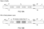
- A1 mode is transformed at the peeling portion to S0 mode which has a propagation speed faster than that of A1 mode, the S0 mode propagates through the peeling portion, the S0 mode goes back to A1 mode again after having passed the peeling portion, and the A1 mode propagates through the object.
- the change of velocity leads to the change of arrival time. Also, it is found that the arrival time of each mode shows its particular change in accordance with the length of the peeling portion.
- FIG. 1 is a diagram illustrating the configuration of a damage detection system 10 that detects damage in a structural composite material Z.
- the structural composite material is the test object for which detection is performed.
- an MFC (Macro Fiber Composite) actuator is used as an oscillator for applying Lamb wave type ultrasonic wave oscillation to a test object.
- the MFC actuator has ultra thin rectangular column shaped piezoelectric ceramic lined up in one direction and embedded in an epoxy resin, with electrodes being adhered to the upper and lower surfaces, and is capable of causing a relatively large in-plane strain to occur in one direction. Because of that characteristic, it is known that an MFC actuator can also be used as an ultrasonic oscillation element. It is also possible to apply another kind of oscillation actuator, such as piezoelectric elements as the oscillator.
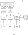
- the damage detection system 10 of this embodiment comprises: an MFC actuator 21 that is adhered to the surface section of a structural composite material Z near the location where damage detection of the structural composite material Z is to be performed; an optical fiber sensor 30 as an oscillation detection sensor that is placed near the location where damage detection of the structural composite material Z is to be performed; a controller 41 for controlling the MFC actuator 21; a spectrum analyzer 42 that detects the wavelength characteristic of reflected light that is obtained from the optical fiber sensor 30; and an arithmetic processing unit 50 that performs arithmetic processing of output values from the spectrum analyzer 42.
- the power source 43 for the spectrum analyzer 42 is also illustrated in the figure.
- the MFC actuator 21 When a driving voltage is applied from the outside, the MFC actuator 21 causes a relatively large in-plane strain to occur in one direction in that plane. Using this, the controller 41 applies a driving voltage to the MFC actuator 21 in order to apply an instantaneous oscillation to the structural composite material Z.
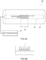
- the optical fiber sensor 30 is an FBG (Fiber Bragg Grating) optical fiber sensor, and as illustrated in FIG. 2A is made from an optical fiber 34 having a grating section 33 located inside the core section 32 that reflects light of a certain wavelength.
- FBG Fiber Bragg Grating
- One of the end sections of the optical fiber 34 is connected to the spectrum analyzer 42, and light covering a specified range of wavelength bands is irradiated from the light source of that spectrum analyzer 42 and enters into the core section 32.
- the light that enters from the spectrum analyzer 42 propagates through the core section 32 and only some of the light wavelengths are reflected by the grating section 33.
- FIG. 2B is a line diagram illustrating change in the refractive index in the advancement direction of the light through the core section 32, and in the figure, the range L illustrates the refractive index in the grating section 33.
- the grating section 33 is constructed such that the refractive index of the core section 32 changes at a fixed cycle.
- the grating section 33 selectively reflects only light of certain wavelength at the boundary sections where the refractive index changes.
- n the effective refractive index of the core
- A the grating interval
- P11 and P12 Pockels coefficients
- v the Poisson's ratio
- ⁇ the applied strain
- ⁇ the temperature coefficient of the fiber material
- ⁇ T the change in temperature
- the amount of strain ⁇ in the grating section 33 changes, and as a result, the wavelength of the reflected light fluctuates according to the amount of strain ⁇ .
- the grating section 33 generates a large strain, and the amount of change in the wavelength ⁇ B fluctuates a lot, however when the oscillation is not transmitted in a good manner from the oscillation source, the grating section 33 generates small strain, and the amount of change in the wavelength ⁇ B fluctuates only a little.
- the MFC causes strain orthogonal to the axial direction of the fibrous piezoelectric element to occur, and the FBG detects strain in the axial direction that occurred in the fibrous optical fiber.
- These elements have a wide frequency characteristic without having a resonant frequency, and because these elements have strong directivity, the propagation path is distinct. Using these two characteristics, the measurement system of this embodiment is able to allow propagation of broadband Lamb waves having directivity.
- the FBG and MFC are both compact and lightweight, are flexible and have a high failure strain, so can be integrated with a laminated plate, they will not fail even under large strain, so have high reliability, and having such characteristics are suitable for use in structural health monitoring.
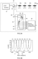
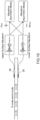
- FIG. 3A illustrates an example of the construction of the optical fiber sensors and the spectrum analyzer that is connected to the sensors.
- the spectrum analyzer 42 comprises a light source 61, an optical circulator 62, an AWG module 63 and a photoelectric converter 60.
- an optical fiber 34 in which four optical fiber sensors 30a to 30d having different reflected wavelengths are arranged in series, is connected to the spectrum analyzer 42.
- the minimum structure is the optical sensors 30.
- the light source 61 is a broadband light source that includes all of the oscillation areas of the reflected wavelengths of the optical fiber sensors 30a to 30d. This is so that even when there is oscillation at the reflected wavelengths of the optical sensors 30a to 30d due to a Lamb wave, it is always possible to obtain the fully reflected light.
- the optical circulator 62 causes light from the light source 62 to advance toward the optical fiber sensors 30a to 30d, and directs the reflected light from the optical fiber sensors 30a to 30d to the optical fiber 69.
- the reflected light that is guided to the optical fiber 69 is led to the input port P0 of the AWG module 63.
- the AWG module 63 has an AWG substrate 64.
- a monolithic integrated lightwave circuit is formed on the AWG substrate 64.
- the lightwave circuit on the AWG substrate 64 has input/output slab waveguides 65, 66, an array waveguide 67 and an output waveguide 68, and forms eight optical filters having different passbands that are connected in parallel to the input port P0.
- the lightwave circuit on the AWG substrate 64 divides the wavelength multiplexed input light into different wavelengths by passing the light through the eight optical filters, and outputs that light in parallel to eight output ports P1 to P8.
- the actual number of output ports is not limited to eight.
- Each of the passbands of the optical filters that corresponds to the eight output ports P1 to P8 are illustrated in the spectrum in FIG. 3B .
- the reflected light that corresponds to the portion where the reflected light input distribution 70 of the optical fiber sensor 3b that has a center reflected wavelength of ⁇ 2 overlaps passband 71 is allowed to pass through one of the optical filters and is outputted to the output port P3, and at the same time, the reflected light that corresponds to the portion that overlaps passband 72 is allowed to pass through another optical filter and is outputted to the output port P4.
- output ports P1 and P2 correspond to the optical fiber sensor 30a having a center reflected wavelength of ⁇ 1
- output ports P5 and P6 correspond to the optical fiber sensor 30c having a center reflected wavelength of ⁇ 3
- output ports P7 and P8 correspond to the optical fiber sensor 30d having a center reflected wavelength of ⁇ 4, and dividing the wavelengths is possible in the same way.
- the minimum structure is one optical fiber sensor, and in this case two optical filters are sufficient.
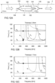
- an input distribution 73T of the reflected light from the optical fiber sensor 30 appears.
- a Lamb wave having the MFC actuator as the oscillation source, propagates through the structural composite material Z, and the optical fiber sensor 30 causes oscillation at the wavelength of the outputted reflected light according to the Lamb wave that is transmitted from the structural composite material Z.
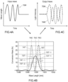
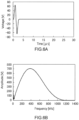
- the oscillation at this wavelength is graphically illustrated by input wave 73W in FIG. 4A .
- the reflected light input distribution 73T illustrated in FIG. 4B alternately shifts upward and downward a little, so there is a repeated increase and decrease in the wavelength value.
- 73C in the figure is the oscillation center having the center wavelength of the reflected light input distribution 73T.
- the center wavelength 75C of the passband 75T of the optical filter is fixed in the area above the oscillation center 73C.
- center wavelength 75C and center wavelength 74C are fixed at positions that are separated by at least the amplitude of the wavelength oscillation of the reflected light from the oscillation center 73C.
- the slope 75T-1 on the lower side of the upper passband 75T crosses the slope 73-T on the upper side of the reflected light input distribution 73T, and the upper passband 75T and the reflected light input distribution 73T overlap with a width that is equal to or greater than the amplitude of the wavelength oscillation.
- the slope 74T-1 on the upper side of the lower passband 74T crosses the slope 73T-2 on the lower side of the reflected input light distribution 73T, and the lower passband 74T and reflected light input distribution 73T overlap with a width that is equal to or greater than the amplitude of the wavelength oscillation.
- the upper optical filter allows the reflected light corresponding to the portion where the reflected light input distribution 73T overlaps the passband 75T to pass, and outputs the reflected light.
- the lower optical filter allows the reflected light corresponding to the portion where the reflected light input distribution 73T overlaps the passband 74T to pass, and outputs the reflected light.
- the output value of the upper filter having passband 75T generates the output wave illustrated in FIG. 4C
- the lower optical filter having passband 74T generates the output wave 74W illustrated in FIG. 4C
- the output wave 74W and output wave 75W have opposite phase wave motion.
- the spectrum analyzer 42 illustrated in FIG. 3 outputs lightwaves to the eight output ports P1 to P8 when oscillated, and these lightwaves are changed to electrical signals by the photoelectric converter 60 and outputted to the outside.
- the output from the spectrum analyzer 42 undergoes A/D conversion by an interface (not illustrated in the figure) and inputted to the arithmetic processing unit 50.
- the arithmetic processing unit 50 comprises a CPU 51 that performs arithmetic processing according to a program, ROM 52 that stores programs for performing various processing and control, RAM 53 that becomes a work area that temporarily stores data and the like for various processing, an interface 54 that makes it possible to transmit data to or receive data from the control unit 41, an interface 55 that inputs data from the spectrum analyzer 42, an image output interface 57 that converts the display data of the processing results to an image signal having a format that is suitable to the display 56, and outputs that signal to the display 56, and a data bus 58 that is used for transmitting various instructions or data between all of the components above.
- the damage detection system 10 together with applying oscillation to a structural composite material Z, which is the object of damage detection, by way of the MFC actuator that is placed on the structural composite material, detects whether or not damage has occurred near the optical fiber sensors 30 according to the propagation state of the oscillation wave that is detected by the optical fiber sensors 30.
- the arithmetic processing unit 50 executes various functions explained below by the CPU 51 using the RAM 53 to perform the processing of the various programs stored in the ROM 52.
- the CPU 51 controls the operation of the control unit 41 so that a driving voltage is applied to the MFC actuator 21.
- any one of the actuators can be selected as the MFC actuator 21, however, when used as an oscillation source, for example, it is preferred that an MFC actuator be selected such that there is a portion between the optical fiber sensors 30 and the grating section 33 where damage to the structural composite material Z occurs easily.
- the CPU 51 performs processing of applying a driving voltage, acquiring output wave data that is outputted in parallel from the spectrum analyzer 42 during the fixed period of oscillation caused by the MFC actuator 21, and storing the acquired data in the RAM 53.
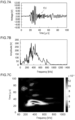
- the CPU 51 issues control instructions, and by way of the MFC actuator 21 applies the ultrasonic oscillation of a Lamb wave to the structural composite material Z, and quantifies and obtains the difference signal of the output wave 74W and the output wave 75W from the optical filter that is obtained during oscillation. For example, the difference signal f(t) illustrated in FIG. 7A is obtained.
- the CPU 51 also performs wavelet conversion of the f(t) data according to Equation (2).
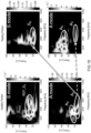
- the f(t) data is converted to propagation intensity distribution data that is expanded 2-dimensionally according to frequency and propagation time. This data corresponds to the propagation intensity distribution of the Lamb wave to the optical fiber sensors 30, and when represented graphically becomes as illustrated in FIG. 7C .
- F a , b ⁇ ⁇ ⁇ ⁇ ⁇ t ⁇ * t a , b dt
- MFC actuators 21, 21 and optical fiber sensors 30, 30 are placed at the same positions on the top and bottom of the structural composite material Z, and the damage detection operation described below is executed.
- the CPU 51 by causing the top and bottom MFC actuators 21, 21 to generate an oscillating wave in the same phase, applies oscillation in just the symmetrical mode to the structural composite material Z, then performs wavelet conversion of the f(t) data as described above and obtains 2-dimensional expanded data according to the frequency and propagation time of just the S mode as illustrated in FIG. 11A .
- the CPU based on the theoretical dispersion curve illustrated in FIG. 8 , specifies a mode, such as the S0 mode, S1 mode, S2 mode and the like, and calculates the propagation time where the maximum wavelet coefficient value occurs for each frequency in the specified mode. For example, when specified modes are the S0 mode and S1 mode, as illustrated in FIG. 23 , the relationship between frequency and time at which the maximum wavelet coefficient value occurs is specified. This is one characteristic value and one measurement result that is extracted from the 2-dimensional expanded data.
- the CPU 51 displays this on the display 56 as illustrated in FIG. 23 .
- the CPU 51 displays the measurement results for a test object for which the damage state is unknown in the same way as and together with the measurement results for a structure for which the damage state is known.
- the tester references this, and through comparison, can estimate whether or not there is damage, and to what extent damage has occurred.
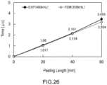
- the propagation time in the S0 mode and the S1 mode increases as the length of the lamination pealing increases, so, as illustrated in FIG. 26 , the CPU 51 displays the amount of increased propagation time with respect to the case when there is no damage.
- the tester references this and can estimate whether or not there is damage, and to what extent damage has occurred.
- the CPU 51 further advances, and based on the multiple measurement results stored in the ROM 52 for a structure for which the damage state is known, and the measurement results for a test object for which the damage state is not known, performs estimation of the extent of the damage that has occurred in the test object, and can display those results on the display 56.
- the CPU 51 by causing the top and bottom MFC actuators 21, 21 to generate an oscillating wave having opposite phase, applies just the asymmetrical mode to the structural composite material Z, performs wavelet conversion of the f(t) data as described above, and obtains 2-dimensional expanded data according to the frequency and propagation time of just the A mode as illustrated in FIG. 11B .
- the CPU 51 specifies a mode such as the A0 mode and A1 mode, and calculates the propagation time at which the maximum wavelet coefficient value occurs for each frequency of the specified mode. For example, when the specified mode is the A1 mode, the relationship between the frequency and the propagation time at which the maximum wavelet coefficient value occurs as illustrated in FIG. 22 is specified. This is one characteristic value and one measurement result that is extracted from the 2-dimensional expanded data.
- the CPU 51 displays this on the display 56 as illustrated in FIG. 22 .
- the CPU 51 displays the measurement results for a test object for which the damage state is not know in the same way as and together with the measurement results for a structure for which the damage state is known.
- the tester references this, and by making a comparison, is able to estimate whether or not there is damage, and to what extent damage has occurred.
- the propagation time in the A1 mode is reduced due to conversion to the S0 mode, which has a faster propagation time than the A1 mode in the damaged area, so the CPU 51 displays the amount of the reduction in propagation time with respect to the case in which there is not damage.
- the tester references this, and is able to estimate whether or not there is damage, and to what extent damage has occurred.
- the CPU 51 calculates the rate of change in the frequency with respect to the propagation time for the A1 mode.
- the approximation straight line of the measurement data sets of each test specimen in the 250 to 450 kHz range is calculated, and the rate of change corresponds to the slope of the approximation straight line.
- This also is one characteristic value and one measurement value that is extracted from 2-dimensional expanded data.
- the CPU 51 displays this rate of change (slope) numerically and in a graph as illustrated in FIG. 24 .
- the CPU 51 displays measurement results for the test object for which the state of damage is unknown in the same way as and together with the measurement results for a structure for which the state of damage is known.
- the tester references this, and by making a comparison, is able to estimate whether or not there is damage, and to what extent damage has occurred.
- the CPU 51 performs estimation of the extent of data to the test object, and can display the results on the display 56.
- the basic data for estimation calculation is the amount of increase in propagation time in the S0 mode and S1 mode described above, and the amount of decrease and rate of change (slope) in the propagation time in the A1 mode.
- the difference signal between the output values of two optical filters was taken to be the basic data for wavelet conversion, however, the invention is not limited to this, and the output value of one optical filter could be taken to be the basic data for wavelet conversion.
- the maximum peak value of the wavelet coefficient for a specified mode was calculated, however, the value of any parameter may be used as long as the parameter is suitable for use in comparing the acquired Lamb wave in specified modes.
- wavelet conversion was applied as the method of conversion for 2-dimensionally expanding the detected values from the optical sensors according to frequency and propagation time, however, the present invention is not limited to this, and it is also possible to apply other conversion methods such as short-time Fourier transformation, chirplet transformation, Wigner transformation, Stockwell transformation, or a combination of any two or more of said transformations.
- averaging was performed by waveforms measured 32,768 times. After that, signal analysis of the obtained received waveform was performed, and the mode dispersion characteristics that were included in the received oscillation wave were expressed in the time-frequency domain.
- a complex Morlet function was used as the window function in signal analysis, and 1D complex continuous wavelet analysis was performed.
- the waveform of the wave received by the FBG sensor, the Fourier spectrum of that waveform, and the wavelet conversion results are illustrated in FIG. 7 .
- a wave component covering a broadband was received without a large peak appearing at the specified frequency.
- a plurality of modes having different speeds and frequencies were observed and found to have mode dispersion.
- the theoretical dispersion curve for identifying each mode that appears in the received oscillation wave is derived.
- FIG. 8 illustrates the theoretical dispersion curve that was derived at the arrival time at a propagation distance of 100 mm in a 3.4 mm CFRP laminated plate that is the same as used in the testing above.
- the arrival time of highdimension modes suddenly becomes late, and where the frequency becomes infinitely large is called the cutoff frequency.
- an FBG sensor is adhered to the same position on both the top and bottom surface, and by taking the sum of the received oscillation waveform of the top and bottom of the plate, it is possible to separate the symmetrical modes, and by taking the difference, it is possible to separate the asymmetrical modes.
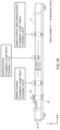
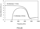
- the propagation speed of a Lamb wave depends on the product of the frequency and plate thickness, so as the plate thickness changes, the mode dispersion of a Lamb wave also changes. Therefore, as illustrated in FIGS. 12A to 12C , when peeling occurs between layers inside a laminated plate, the plate thickness of the propagation path at the area of peeling is less than in a healthy section, so the mode dispersion is different in healthy sections and peeling sections. Due to this change in mode dispersion, it is thought that mode conversion occurs in the Lamb wave that propagated through a healthy section, and propagates through a peeling section in a different mode form than in a healthy section.
- a quasi-isotropic CFRP laminated plate (T700S/2500, Toray Industries Inc., [45/0/-45]3s, thickness: 3.4 mm) was used to simulate the case in which peeling between layers occurs in the center in the thickness direction of the plate.
- Mode identification of a received Lamb wave is performed by mode separation, so in order to measure the mode dispersion in a peeling section it is necessary to adhere an FBG sensor to the interior surface of the simulated peeling between layers.
- the MFC (M-2814-P2) that was used had a length of 6 mm, a width of 14 mm and a thickness of 0.3 mm, and one was adhered to both the top and bottom surface of the laminated plate.
- FBG sensors were adhered to the top and bottom surface of the laminated plate at two points; a distance 30 mm from the tip end of the MFC where the plate thickness was 3.4 mm (healthy section), and at a distance 70 mm where the plate thickness was 1.7 mm (peeling section), and these sensors received the Lamb wave.
- the FBG sensors (Fujikura Ltd.) that were used in testing had a sensor length 1.5 mm, and diameter with polyimide coating of 150 ⁇ m.
- Aron Alpha (Konishi Co., Ltd.) was used for adhering the elements.
- the mode conversion behavior of the S mode that was found by performing oscillation in just the S (symmetrical) mode using the MFC on both the top and bottom surfaces is illustrated in FIG. 14
- the mode conversion behavior of the A mode that was found by performing oscillation in just the A (asymmetrical) mode is illustrated in FIG. 15 .
- the piezoelectric effect was applied as the coefficient of thermal expansion in the direction of expansion of the MFC and simulated.
- the time history of the strain in the x direction was calculated at the three oscillation receiving points illustrated in FIG. 16 (healthy section: 20 mm propagation distance 20, 3.4 mm plate thickness; peeling section: 60 mm propagation distance, 1.7 mm plate thickness; and healthy section (after passing the peeling section): 100 mm propagation distance, 3.4 mm plate thickness), and this was taken to be the received oscillation waveform.
- the mode conversion behavior in the S mode that was found by performing oscillation in only the S (symmetrical) mode using both the top and bottom MFC is illustrated in FIG. 17
- the mode conversion behavior in the A mode that was found by performing oscillation in only the A (asymmetrical) mode is illustrated in FIG. 18 .
- the mode during propagation through a peeling section and the mode during propagation though a healthy section differ.
- the mode during propagation through a peeling section and the mode during propagation though a healthy section differ.
- the propagation speeds in the A1 mode in healthy sections (3.4 mm plate thickness) and in the S0 mode in peeling section (1.7 mm plate thickness) differ, with the speed of the S0 mode being faster than that of the A1 mode. Therefore, the arrival time of oscillation in the A1 mode that is received by the FBG sensor is earlier when peeling has occurred than when healthy.
- This change in the arrival time occurs due to the difference in propagation speeds of a mode propagating though healthy sections and a mode propagating through peeling sections, and the length of the peeling. Therefore, by taking this difference as an index, it is possible to detect peeling between layers, and to quantitatively evaluate the peeling length.
- the effectiveness of the present invention is illustrated by verifying through testing whether or not there is actually a change in arrival time of a wave after passing through a peeling section.
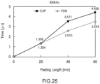
- a linearly approximated straight line is calculated from a plot of maximum amplitude values in the frequency ranges where change occurred in the arrival time, and using that approximated straight line, the following indices were found. The indices were found from test results and analysis results. The results of plotting the indices for each peeling length are illustrated in FIG. 24 , FIG. 25 and FIG. 26 .
- FIG. 24 illustrates the slope of the mode dispersion of the 250 to 400 kHz A1 mode
- FIG. 25 illustrates the amount of decrease in the arrival time of the A1 mode at 300 kHz
- FIG. 26 illustrates the amount of increase in the arrival time of the S0 and S1 modes at 400 kHz (analysis was at 350 kHz).
- the validity of the peeling detection method of the present invention which uses the change in speed of a Lamb wave due to mode conversion, was verified through testing and analysis. As a result, it was confirmed that the change in speed in the peeling sections was observed as the change in arrival time.
- peeling length could be quantitatively evaluated using the slope of the mode dispersion in the A1 mode, the amount of decrease in the arrival time of the A1 mode and the increase in the arrival time of the S0 and S1 modes as indices.
Landscapes
- Physics & Mathematics (AREA)
- General Health & Medical Sciences (AREA)
- Immunology (AREA)
- Health & Medical Sciences (AREA)
- Life Sciences & Earth Sciences (AREA)
- Chemical & Material Sciences (AREA)
- Analytical Chemistry (AREA)
- Biochemistry (AREA)
- General Physics & Mathematics (AREA)
- Pathology (AREA)
- Signal Processing (AREA)
- Engineering & Computer Science (AREA)
- Acoustics & Sound (AREA)
- Mathematical Physics (AREA)
- Spectroscopy & Molecular Physics (AREA)
- Investigating Or Analyzing Materials By The Use Of Ultrasonic Waves (AREA)
- Investigating Materials By The Use Of Optical Means Adapted For Particular Applications (AREA)
- Measurement Of Mechanical Vibrations Or Ultrasonic Waves (AREA)
Claims (11)
- System (10) zur Schadensdiagnose zum Diagnostizieren eines Schadens, der an oder in einem Objekt (Z) aufgetreten ist, wobei das System (10) aufweist:einen Oszillator (21) zum Anlegen einer breitbandigen Ultraschallschwingung an das Objekt (Z), um eine breitbandige Lamb-Welle innerhalb des Objekts (Z) zu erzeugen;einen Schwingungserfassungssensor (30) zum Erfassen der Breitband-Lamb-Welle von dem Objekt (Z), wobei die erfasste Breitband-Lamb-Welle mindestens einen Lamb-Wellenmodus aufweist; undeine Verarbeitungseinheit (50), die mit dem Oszillator (21) und dem Schwingungserfassungssensor (30) verbunden ist, zum(1) Erhalten von Zeit-Frequenz-Transformationsdaten durch Durchführen einer Zeit-Frequenz-Transformation an der vom Schwingungserfassungssensor (30) erfassten Breitband-Lamb-Welle, wobei die Zeit-Frequenz-Transformationsdaten eine Ausbreitungszeit des mindestens einen Lamb-Wellenmodus anzeigen und die Ausbreitungszeit die Zeit ist, die die Lamb-Welle benötigt, um sich vom Oszillator bis zum Schwingungserfassungssensor (30) auszubreiten, und(2) Identifizieren, basierend auf der Ausbreitungszeit des mindestens einen Lamb-Wellenmodus in den Zeit-Frequenz-Transformationsdaten, ob der Schaden auf oder innerhalb des Objekts (Z) aufgetreten ist oder nicht, und/oder des Ausmaßes des Schadens, der auf oder innerhalb des Objekts (Z) aufgetreten ist,wobeidie Lamb-Welle mindestens eines Modus mehrere Wellen mit voneinander verschiedenen Frequenzen aufweist,die Verarbeitungseinheit (50) im Identifizierungsprozess (2): Ausbreitungszeiten von zwei der mehreren Wellen berechnet; ein Änderungsverhältnis der Ausbreitungszeiten mittels Dividieren einer Differenz der zwei Ausbreitungszeiten durch eine Differenz der Frequenzen der zwei Wellen berechnet; und basierend darauf, ob das Änderungsverhältnis mit einem Referenzwert übereinstimmt oder nicht, der ein Änderungsverhältnis für eine Struktur ist, für die ein Schadenszustand bekannt ist, identifiziert, ob der Schaden an oder innerhalb des Objekts aufgetreten ist oder nicht, und/oder das Ausmaß des Schadens identifiziert, der an oder innerhalb des Objekts aufgetreten ist, undder mindestens eine Modus der Modus A1 ist.
- System zur Schadensdiagnose nach Anspruch 1, wobeidie breitbandige Lamb-Welle zwei oder mehr Lamb-Wellenmodi aufweist; undder Identifizierungsprozess (2) einen Auswahlschritt aufweist, um den mindestens einen Lamb-Wellenmodus aus den zwei oder mehr Lamb-Wellenmodi auszuwählen, um mit dem Referenzwert verglichen zu werden.
- System zur Schadensdiagnose nach Anspruch 1 oder 2, wobei
die von der Verarbeitungseinheit (50) erhaltenen Zeit-Frequenz-Transformationsdaten zweidimensionale Ausbreitungsintensitätsverteilungsdaten sind, bei denen die Frequenz eine der beiden Dimensionen und die Ausbreitungszeit die andere ist. - System zur Schadensdiagnose nach einem der Ansprüche 1 bis 3, wobei
die Ausbreitungszeit des mindestens einen Lamb-Wellenmodus eine Ausbreitungszeit eines maximalen Intensitätsanteils mindestens einer der mehreren Wellen ist. - System zur Schadensdiagnose nach Anspruch 2 oder einem der Ansprüche 3 bis 4 in Abhängigkeit von Anspruch 2, wobeidas System zwei Oszillatoren aufweist, mit einem Oszillator zur Befestigung an einer Oberfläche in Dickenrichtung des Objekts und der andere Oszillator zur Befestigung an der anderen Oberfläche in Dickenrichtung des Objekts (Z); unddie Verarbeitungseinheit (50) einen Schwingungssteuerungsprozess ausführt, um die Oszillatoren zu steuern, und den Schwingungssteuerungsprozess und den Auswahlschritt unter der folgenden Bedingung ausführt, wobeidie Bedingung derart ist, dass die Verarbeitungseinheit (50) im Schwingungssteuerungsprozess die zwei Oszillatoren so steuert, dass ein asymmetrischer Lamb-Wellenmodus im Objekt (Z) erzeugt wird, und den asymmetrischen Lamb-Wellenmodus im Auswahlschritt auswählt,der asymmetrische Lamb-Wellenmodus eine Lamb-Welle des A1-Modus ist.
- System zur Schadensdiagnose nach einem der Ansprüche 2 bis 4, wobeidieses System (10) zwei Schwingungserfassungssensoren aufweist, mit einem Schwingungserfassungssensor, der eingerichtet ist, an einer Oberfläche in Dickenrichtung des Objekts (Z) befestigt zu werden, und dem anderen Schwingungserfassungssensor, der eingerichtet ist, an der anderen Oberfläche in Dickenrichtung des Objekts (Z) befestigt zu werden; unddie Verarbeitungseinheit die Prozesse (1) und (2) unter der folgenden Bedingung ausführt; wobeidie Bedingung derart ist, dass die Verarbeitungseinheit (50) in dem Prozess (1) des Erhaltens Daten erzeugt, in denen der symmetrische Modus ausgelöscht ist und der asymmetrische Modus betont ist, durch Subtrahieren der von den beiden Schwingungserfassungssensoren erfassten breitbandigen Lamb-Wellen, und dann die Verarbeitungseinheit Zeit-Frequenz-Transformationsdaten erhält, durch Durchführen der Zeit-Frequenz-Transformation an den erzeugten Daten, und im Identifizierungsprozess (2) einen asymmetrischen Lamb-Wellenmodus auswählt; undder asymmetrische Lamb-Wellenmodus eine Lamb-Welle des A1-Modus ist.
- System zur Schadensdiagnose nach einem der Ansprüche 1 bis 6, wobei die Zeit-Frequenz-Transformation eine der Wavelet-Transformation, der Kurzzeit-Fourier-Transformation, der Chirplet-Transformation, der Wigner-Transformation und der Stockwell-Transformation oder eine Kombination von zwei oder mehreren der Transformationen ist.
- System zur Schadensdiagnose nach einem der Ansprüche 1 bis 7, wobei der Oszillator (21) eingerichtet ist, am Objekt (Z) befestigt zu werden.
- System zur Schadensdiagnose nach einem der Ansprüche 1 bis 8, wobei der Schwingungserfassungssensor (30) eingerichtet ist, am Objekt (Z) befestigt zu werden.
- Verfahren zur Schadensdiagnose zur Diagnose von Schäden, die an oder in einem Objekt (Z) aufgetreten sind, wobei das Verfahren verwendet:einen Oszillator (21) zum Anlegen einer breitbandigen Ultraschallschwingung an das Objekt, um eine breitbandige Lamb-Welle innerhalb des Objekts zu erzeugen,einen Schwingungserfassungssensor (30) zum Erfassen der Breitband-Lamb-Welle von dem Objekt, wobei die erfasste Breitband-Lamb-Welle mindestens einen Lamb-Wellenmodus aufweist; undeine Verarbeitungseinheit (50), die mit dem Oszillator (21) und dem Schwingungserfassungssensor (30) verbunden ist, unddas Verfahren die Schritte aufweist:(1) Erhalten von Zeit-Frequenz-Transformationsdaten durch Durchführen einer Zeit-Frequenz-Transformation an der vom Schwingungserfassungssensor (30) erfassten Breitband-Lamb-Welle, wobei die Zeit-Frequenz-Transformationsdaten eine Ausbreitungszeit des mindestens einen Lamb-Wellenmodus anzeigen und die Ausbreitungszeit die Zeit ist, die die Lamb-Welle benötigt, um sich vom Oszillator bis zum Schwingungserfassungssensor auszubreiten; und(2) Identifizieren, basierend auf der Ausbreitungszeit des mindestens einen Lamb-Wellenmodus in den Zeit-Frequenz-Transformationsdaten, ob der Schaden auf oder innerhalb des Objekts (Z) aufgetreten ist oder nicht, und/oder des Ausmaßes des Schadens, der auf oder innerhalb des Objekts (Z) aufgetreten ist;wobeidie Lamb-Welle mindestens eines Modus mehrere Wellen mit voneinander verschiedenen Frequenzen aufweist,der Identifizierungsschritt (2) aufweist: Berechnen von Ausbreitungszeiten von zwei der mehreren Wellen; Berechnen eines Änderungsverhältnisses der Ausbreitungszeiten mittels Dividieren einer Differenz der zwei Ausbreitungszeiten durch eine Differenz der Frequenzen der zwei Wellen, und basierend darauf, ob das Änderungsverhältnis mit einem Referenzwert übereinstimmt oder nicht, der ein Änderungsverhältnis für eine Struktur ist, für die ein Schadenszustand bekannt ist, Identifizieren, ob der Schaden an oder innerhalb des Objekts aufgetreten ist oder nicht, und/oder Identifizieren des Ausmaßes des Schadens, der an oder innerhalb des Objekts aufgetreten ist, undder mindestens eine Modus der A1-Modus ist.
- Verfahren zur Schadensdiagnose nach Anspruch 10, wobei
die Zeit-Frequenz-Transformation eine der Wavelet-Transformation, der Kurzzeit-Fourier-Transformation, der Chirplet-Transformation, der Wigner-Transformation und der Stockwell-Transformation oder eine Kombination von zwei oder mehreren der Transformationen ist.
Applications Claiming Priority (1)
| Application Number | Priority Date | Filing Date | Title |
|---|---|---|---|
| JP2010058784A JP5629481B2 (ja) | 2010-03-16 | 2010-03-16 | 損傷診断システム |
Publications (2)
| Publication Number | Publication Date |
|---|---|
| EP2369334A1 EP2369334A1 (de) | 2011-09-28 |
| EP2369334B1 true EP2369334B1 (de) | 2023-06-07 |
Family
ID=44010056
Family Applications (1)
| Application Number | Title | Priority Date | Filing Date |
|---|---|---|---|
| EP11157867.0A Active EP2369334B1 (de) | 2010-03-16 | 2011-03-11 | System und Verfahren zur Schadensdiagnose |
Country Status (4)
| Country | Link |
|---|---|
| US (2) | US20110231112A1 (de) |
| EP (1) | EP2369334B1 (de) |
| JP (1) | JP5629481B2 (de) |
| CN (1) | CN102192954B (de) |
Families Citing this family (38)
| Publication number | Priority date | Publication date | Assignee | Title |
|---|---|---|---|---|
| US8499632B1 (en) * | 2010-08-23 | 2013-08-06 | The Boeing Company | Characterizing anomalies in a laminate structure |
| US8977507B2 (en) | 2011-01-21 | 2015-03-10 | The United States Of America As Represented By The Secretary Of The Navy | Event detection system user interface system coupled to multiple sensors including an impact detection system |
| DE102012202189B3 (de) * | 2012-02-14 | 2013-02-07 | Sonotec Ultraschallsensorik Halle Gmbh | Verfahren und Vorrichtung zur Wavelet basierten Laufzeitmessung von Ultraschallimpulsen |
| GB2521661A (en) * | 2013-12-27 | 2015-07-01 | Xsens As | Apparatus and method for measuring flow |
| CN104007175B (zh) * | 2014-05-09 | 2017-04-05 | 华南理工大学 | 一种悬臂柔性梁多裂缝损伤识别装置及方法 |
| CN103971012B (zh) * | 2014-05-20 | 2017-01-18 | 南京信息工程大学 | 一种基于赛利斯模型和分数阶微分的兰姆波信号消噪方法 |
| CN103954697B (zh) * | 2014-05-20 | 2016-09-28 | 南京信息工程大学 | 一种基于分数阶微分的兰姆波去噪方法 |
| WO2015199839A1 (en) * | 2014-06-26 | 2015-12-30 | Baker Hughes Incorporated | Ofdr system for localized vibration detection |
| JP6777301B2 (ja) * | 2015-03-10 | 2020-10-28 | 日本電気株式会社 | 検査装置及び検査方法 |
| JP6317708B2 (ja) * | 2015-06-12 | 2018-04-25 | 株式会社Subaru | 超音波探傷システム、超音波探傷方法及び航空機構造体 |
| CN105044212A (zh) * | 2015-06-30 | 2015-11-11 | 清华大学 | 一种多模态超声Lamb波复杂缺陷层析成像方法 |
| JP6329188B2 (ja) * | 2016-02-29 | 2018-05-23 | 株式会社Subaru | 超音波検査システム、超音波検査方法及び航空機構造体 |
| WO2017149658A1 (ja) * | 2016-03-01 | 2017-09-08 | 三菱電機株式会社 | 超音波測定装置及び超音波測定方法 |
| CN108885194B (zh) * | 2016-04-06 | 2020-07-03 | 株式会社斯巴鲁 | 超声波检查系统、超声波检查方法及航空器结构体 |
| CN108896935B (zh) * | 2016-04-08 | 2020-11-13 | 北京信息科技大学 | 一种利用超声脉冲诱发光栅变形测量磁场的方法 |
| KR101880194B1 (ko) * | 2016-05-30 | 2018-07-20 | 한국과학기술원 | 구조물의 진단 방법 및 진단 시스템 |
| CN106290566B (zh) * | 2016-08-04 | 2019-03-08 | 南京航空航天大学 | 非接触式评估复合材料结构的疲劳特性的方法及系统 |
| GB2545044B (en) * | 2016-08-11 | 2018-02-07 | Guided Ultrasonics Ltd | Determining a thickness of a region of wall-or plate-like structure |
| ES2928656T3 (es) * | 2016-09-26 | 2022-11-21 | Subaru Corp | Sistema de detección de daños y método de detección de daños |
| CN106441383B (zh) * | 2016-10-10 | 2019-08-23 | 山东大学 | 一种基于光纤光栅传感的主动激励式压滤机滤板健康检测系统 |
| CN108508097B (zh) * | 2017-02-28 | 2021-03-02 | 香港理工大学 | 一种基于光纤超声导波技术的铁轨裂纹监测系统 |
| CN110892261B (zh) | 2017-07-27 | 2023-05-30 | 株式会社斯巴鲁 | 超声波检查系统的制造方法 |
| CN108008021B (zh) * | 2018-01-09 | 2023-10-13 | 东莞理工学院 | 用于钢轨探伤的超声导波斜探头及其探伤方法 |
| KR102813799B1 (ko) * | 2018-05-04 | 2025-05-29 | 더 보잉 컴파니 | 음향 방출 시험을 위한 방법 및 장치 |
| CN110497425A (zh) * | 2018-05-17 | 2019-11-26 | 张家港市光武智能科技有限公司 | 一种基于兰姆波与瑞利波的机器人皮肤 |
| JP7131967B2 (ja) * | 2018-05-30 | 2022-09-06 | 株式会社Subaru | 光検査システム、光検査方法及び航空機構造体 |
| JP6748675B2 (ja) * | 2018-06-29 | 2020-09-02 | 株式会社Subaru | 航空機管理システム |
| CN109298076B (zh) * | 2018-11-13 | 2021-05-04 | 中国核动力研究设计院 | 一种基于Lamb波的主动式阀门内漏损伤检测系统及方法 |
| EP3896442B1 (de) * | 2019-01-15 | 2024-12-18 | Yamaha Hatsudoki Kabushiki Kaisha | Vorrichtung zur erkennung des internen zustands und fahrzeug |
| CN110485296A (zh) * | 2019-08-15 | 2019-11-22 | 武汉理工大学 | 基于宏纤维复合材料正交异性钢桥面板疲劳振动减振方法 |
| CN111175379B (zh) * | 2020-01-21 | 2022-08-02 | 南京邮电大学 | 一种基于同步压缩小波变换的Lamb波板结构健康监测方法 |
| KR102323836B1 (ko) * | 2020-03-19 | 2021-11-08 | 부경대학교 산학협력단 | 객체 손상 검사 장치 및 이를 이용한 객체 손상 검사 방법 |
| CN111551630B (zh) * | 2020-04-23 | 2021-07-13 | 上海大学 | 一种基于空间-波数滤波器的损伤无波速定位方法 |
| CN111983032B (zh) * | 2020-08-25 | 2023-10-10 | 中国科学院电工研究所 | 一种光学元件损伤的在线监测方法及系统 |
| DE102020123975A1 (de) | 2020-09-15 | 2022-03-17 | Technische Universität Dresden, Körperschaft des öffentlichen Rechts | Vorrichtung und Messverfahren zur ortsaufgelösten in-situ Erfassung von Flüssigwasser auf einer Trägerstruktur sowie deren Verwendung in einem Brennstoffzellenstapel und in Plattenwärmeübertrager-Anwendungen |
| CN114428119B (zh) * | 2022-01-20 | 2023-11-21 | 重庆大学 | 一种用于反演各向异性特征的复合材料弹性常数的方法 |
| US20230334646A1 (en) * | 2022-04-14 | 2023-10-19 | Antech Systems, Inc. | System and Method for Mode Identification and Extraction in Guided Wave Signals and nondestructive methods for automatically sensing, locating, and/or characterizing problems in structures |
| CN115307774B (zh) * | 2022-08-10 | 2024-04-26 | 山东大学 | 一种基于超声导波的物体表面温度场检测方法及系统 |
Citations (2)
| Publication number | Priority date | Publication date | Assignee | Title |
|---|---|---|---|---|
| US20090078049A1 (en) * | 2007-09-25 | 2009-03-26 | The Regents Of The University Of California | Non-contact feature detection using ultrasonic lamb waves |
| US20090326834A1 (en) * | 2004-11-12 | 2009-12-31 | Sundaresan Mannur J | Systems, methods and computer program products for characterizing structural events |
Family Cites Families (16)
| Publication number | Priority date | Publication date | Assignee | Title |
|---|---|---|---|---|
| JPS59173753A (ja) * | 1983-03-23 | 1984-10-01 | Mitsubishi Electric Corp | 試料板体の性状を判定するための板波送受信装置 |
| IT1262407B (it) * | 1993-09-06 | 1996-06-19 | Finmeccanica Spa | Strumentazione utilizzante componenti in ottica integrata per la diagnostica di parti con sensori a fibra ottica inclusi o fissati sulla superficie. |
| US5814730A (en) * | 1996-06-10 | 1998-09-29 | Institute Of Paper Science And Technology And Georgia Institute Of Technology | Material characteristic testing method and apparatus using interferometry to detect ultrasonic signals in a web |
| JP3957276B2 (ja) * | 2001-05-14 | 2007-08-15 | 富士フイルム株式会社 | 超音波受信装置 |
| AU2004277167A1 (en) * | 2003-09-22 | 2005-04-07 | Kim Hyeung-Yun | Methods for monitoring structural health conditions |
| JP4377642B2 (ja) | 2003-09-26 | 2009-12-02 | 富士重工業株式会社 | 構造用複合材料の損傷探知システム |
| JP4470655B2 (ja) * | 2004-09-01 | 2010-06-02 | Jfeスチール株式会社 | 超音波によるスポット溶接部の評価方法及び装置 |
| JP4742675B2 (ja) * | 2005-05-20 | 2011-08-10 | 三菱化学株式会社 | 筒状体内面付着層の厚さ測定方法 |
| JP2007023271A (ja) | 2005-06-16 | 2007-02-01 | Toyobo Co Ltd | ポリエステル重合触媒およびこれを用いて製造されたポリエステル並びにポリエステルの製造方法 |
| JP4804957B2 (ja) | 2006-02-27 | 2011-11-02 | 富士重工業株式会社 | 損傷探知システム |
| WO2008005311A2 (en) * | 2006-06-30 | 2008-01-10 | Carnegie Mellon University | Methods, apparatuses, and systems for damage detection |
| FR2905208B1 (fr) * | 2006-08-28 | 2008-12-19 | St Microelectronics Sa | Filtre a resonateurs a ondes de lamb couples. |
| US8419643B2 (en) * | 2006-09-21 | 2013-04-16 | Artann Laboratories Inc. | Ultrasonic method and apparatus for assessment of bone |
| US7809513B2 (en) * | 2007-04-16 | 2010-10-05 | Acellent Technologies, Inc. | Environmental change compensation in a structural health monitoring system |
| EP2232123B1 (de) * | 2008-01-11 | 2014-09-17 | PII Limited | Pipeline-untersuchungsgerät und -methode mit zwei verschiedenen ultraschallwellen |
| JP4553047B2 (ja) * | 2008-03-12 | 2010-09-29 | セイコーエプソン株式会社 | ラム波型共振子及び発振器 |
-
2010
- 2010-03-16 JP JP2010058784A patent/JP5629481B2/ja active Active
-
2011
- 2011-03-11 EP EP11157867.0A patent/EP2369334B1/de active Active
- 2011-03-14 US US13/047,517 patent/US20110231112A1/en not_active Abandoned
- 2011-03-16 CN CN201110063840.9A patent/CN102192954B/zh active Active
-
2014
- 2014-07-18 US US14/335,182 patent/US10054568B2/en active Active
Patent Citations (2)
| Publication number | Priority date | Publication date | Assignee | Title |
|---|---|---|---|---|
| US20090326834A1 (en) * | 2004-11-12 | 2009-12-31 | Sundaresan Mannur J | Systems, methods and computer program products for characterizing structural events |
| US20090078049A1 (en) * | 2007-09-25 | 2009-03-26 | The Regents Of The University Of California | Non-contact feature detection using ultrasonic lamb waves |
Also Published As
| Publication number | Publication date |
|---|---|
| US10054568B2 (en) | 2018-08-21 |
| CN102192954A (zh) | 2011-09-21 |
| US20110231112A1 (en) | 2011-09-22 |
| JP2011191230A (ja) | 2011-09-29 |
| US20140330528A1 (en) | 2014-11-06 |
| CN102192954B (zh) | 2016-07-20 |
| EP2369334A1 (de) | 2011-09-28 |
| JP5629481B2 (ja) | 2014-11-19 |
Similar Documents
| Publication | Publication Date | Title |
|---|---|---|
| EP2369334B1 (de) | System und Verfahren zur Schadensdiagnose | |
| US7470888B2 (en) | Damage detection system | |
| EP3112857B1 (de) | System mit einem flugzeugbauteil, das mit einem ultraschallprüfsystem verbunden ist, und ultraschallprüfverfahren | |
| EP1927837B1 (de) | Stoßdetektionssystem | |
| EP3070467B1 (de) | Ultraschalltestsystem, ultraschalltestverfahren und verfahren zur herstellung eines flugzeugbauteils | |
| US8922789B2 (en) | Displacement measuring device and displacement measuring method | |
| JPH11316214A (ja) | 材料の材料試験システム及び方法並びに材料及びその製造方法 | |
| JP2011149828A (ja) | 振動検出システム、該システムを用いた装置及び振動検出方法 | |
| CN110554091B (zh) | 光学检查系统、光学检查方法以及航空器结构体 | |
| Wang et al. | Multifrequency identification and exploitation in Lamb wave inspection | |
| Karpenko et al. | Multitechnique monitoring of fatigue damage in adhesively bonded composite lap-joints | |
| EP3885732B1 (de) | System zur überwachung der strukturellen gesundheit | |
| Wee | Enhancement of ultrasonic lamb wave transfer to fiber bragg grating sensors through remote bonding | |
| Parali | Guided Wave Structural Health Monitoring Using Remote Excitation Through Thin Wire Waveguides | |
| Miesen et al. | Lamb wave detection in prepreg composite materials with fibre Bragg grating sensors | |
| Willberry | The development of fibre-optic acoustic emission sensors for structural health monitoring | |
| Tsuda et al. | Impact damage monitoring in CFRP using fiber Bragg grating ultrasound sensors | |
| Keulen et al. | Design of an Embedded Sensor Network for Manufacturing Process Monitoring, Quality Control Management and Structural Health Assessment of Advanced Composite Structures | |
| Staszewski | Health and usage monitoring of aerospace structures | |
| Sarbaz | Reference free damage detection by guided waves with using FBG sensors | |
| Tak et al. | Damage Assessment in Advanced Composite Structures Using Embedded Fibre Bragg Grating Sensors | |
| ITPI20080103A1 (it) | Metodo e dispositivo per misure di posizione e di massa |
Legal Events
| Date | Code | Title | Description |
|---|---|---|---|
| PUAI | Public reference made under article 153(3) epc to a published international application that has entered the european phase |
Free format text: ORIGINAL CODE: 0009012 |
|
| AK | Designated contracting states |
Kind code of ref document: A1 Designated state(s): AL AT BE BG CH CY CZ DE DK EE ES FI FR GB GR HR HU IE IS IT LI LT LU LV MC MK MT NL NO PL PT RO RS SE SI SK SM TR |
|
| AX | Request for extension of the european patent |
Extension state: BA ME |
|
| 17P | Request for examination filed |
Effective date: 20120327 |
|
| RAP1 | Party data changed (applicant data changed or rights of an application transferred) |
Owner name: FUJI JUKOGYO KABUSHIKI KAISHA Owner name: THE UNIVERSITY OF TOKYO |
|
| 17Q | First examination report despatched |
Effective date: 20160506 |
|
| RAP1 | Party data changed (applicant data changed or rights of an application transferred) |
Owner name: THE UNIVERSITY OF TOKYO Owner name: SUBARU CORPORATION |
|
| STAA | Information on the status of an ep patent application or granted ep patent |
Free format text: STATUS: EXAMINATION IS IN PROGRESS |
|
| GRAP | Despatch of communication of intention to grant a patent |
Free format text: ORIGINAL CODE: EPIDOSNIGR1 |
|
| STAA | Information on the status of an ep patent application or granted ep patent |
Free format text: STATUS: GRANT OF PATENT IS INTENDED |
|
| INTG | Intention to grant announced |
Effective date: 20220921 |
|
| GRAS | Grant fee paid |
Free format text: ORIGINAL CODE: EPIDOSNIGR3 |
|
| GRAA | (expected) grant |
Free format text: ORIGINAL CODE: 0009210 |
|
| STAA | Information on the status of an ep patent application or granted ep patent |
Free format text: STATUS: THE PATENT HAS BEEN GRANTED |
|
| AK | Designated contracting states |
Kind code of ref document: B1 Designated state(s): AL AT BE BG CH CY CZ DE DK EE ES FI FR GB GR HR HU IE IS IT LI LT LU LV MC MK MT NL NO PL PT RO RS SE SI SK SM TR |
|
| REG | Reference to a national code |
Ref country code: GB Ref legal event code: FG4D |
|
| REG | Reference to a national code |
Ref country code: CH Ref legal event code: EP Ref country code: AT Ref legal event code: REF Ref document number: 1576588 Country of ref document: AT Kind code of ref document: T Effective date: 20230615 Ref country code: DE Ref legal event code: R096 Ref document number: 602011073909 Country of ref document: DE |
|
| REG | Reference to a national code |
Ref country code: LT Ref legal event code: MG9D |
|
| REG | Reference to a national code |
Ref country code: NL Ref legal event code: MP Effective date: 20230607 |
|
| PG25 | Lapsed in a contracting state [announced via postgrant information from national office to epo] |
Ref country code: SE Free format text: LAPSE BECAUSE OF FAILURE TO SUBMIT A TRANSLATION OF THE DESCRIPTION OR TO PAY THE FEE WITHIN THE PRESCRIBED TIME-LIMIT Effective date: 20230607 Ref country code: NO Free format text: LAPSE BECAUSE OF FAILURE TO SUBMIT A TRANSLATION OF THE DESCRIPTION OR TO PAY THE FEE WITHIN THE PRESCRIBED TIME-LIMIT Effective date: 20230907 Ref country code: ES Free format text: LAPSE BECAUSE OF FAILURE TO SUBMIT A TRANSLATION OF THE DESCRIPTION OR TO PAY THE FEE WITHIN THE PRESCRIBED TIME-LIMIT Effective date: 20230607 |
|
| REG | Reference to a national code |
Ref country code: AT Ref legal event code: MK05 Ref document number: 1576588 Country of ref document: AT Kind code of ref document: T Effective date: 20230607 |
|
| PG25 | Lapsed in a contracting state [announced via postgrant information from national office to epo] |
Ref country code: RS Free format text: LAPSE BECAUSE OF FAILURE TO SUBMIT A TRANSLATION OF THE DESCRIPTION OR TO PAY THE FEE WITHIN THE PRESCRIBED TIME-LIMIT Effective date: 20230607 Ref country code: NL Free format text: LAPSE BECAUSE OF FAILURE TO SUBMIT A TRANSLATION OF THE DESCRIPTION OR TO PAY THE FEE WITHIN THE PRESCRIBED TIME-LIMIT Effective date: 20230607 Ref country code: LV Free format text: LAPSE BECAUSE OF FAILURE TO SUBMIT A TRANSLATION OF THE DESCRIPTION OR TO PAY THE FEE WITHIN THE PRESCRIBED TIME-LIMIT Effective date: 20230607 Ref country code: LT Free format text: LAPSE BECAUSE OF FAILURE TO SUBMIT A TRANSLATION OF THE DESCRIPTION OR TO PAY THE FEE WITHIN THE PRESCRIBED TIME-LIMIT Effective date: 20230607 Ref country code: HR Free format text: LAPSE BECAUSE OF FAILURE TO SUBMIT A TRANSLATION OF THE DESCRIPTION OR TO PAY THE FEE WITHIN THE PRESCRIBED TIME-LIMIT Effective date: 20230607 Ref country code: GR Free format text: LAPSE BECAUSE OF FAILURE TO SUBMIT A TRANSLATION OF THE DESCRIPTION OR TO PAY THE FEE WITHIN THE PRESCRIBED TIME-LIMIT Effective date: 20230908 |
|
| PG25 | Lapsed in a contracting state [announced via postgrant information from national office to epo] |
Ref country code: FI Free format text: LAPSE BECAUSE OF FAILURE TO SUBMIT A TRANSLATION OF THE DESCRIPTION OR TO PAY THE FEE WITHIN THE PRESCRIBED TIME-LIMIT Effective date: 20230607 |
|
| PG25 | Lapsed in a contracting state [announced via postgrant information from national office to epo] |
Ref country code: SK Free format text: LAPSE BECAUSE OF FAILURE TO SUBMIT A TRANSLATION OF THE DESCRIPTION OR TO PAY THE FEE WITHIN THE PRESCRIBED TIME-LIMIT Effective date: 20230607 |
|
| PG25 | Lapsed in a contracting state [announced via postgrant information from national office to epo] |
Ref country code: IS Free format text: LAPSE BECAUSE OF FAILURE TO SUBMIT A TRANSLATION OF THE DESCRIPTION OR TO PAY THE FEE WITHIN THE PRESCRIBED TIME-LIMIT Effective date: 20231007 |
|
| PG25 | Lapsed in a contracting state [announced via postgrant information from national office to epo] |
Ref country code: SM Free format text: LAPSE BECAUSE OF FAILURE TO SUBMIT A TRANSLATION OF THE DESCRIPTION OR TO PAY THE FEE WITHIN THE PRESCRIBED TIME-LIMIT Effective date: 20230607 Ref country code: SK Free format text: LAPSE BECAUSE OF FAILURE TO SUBMIT A TRANSLATION OF THE DESCRIPTION OR TO PAY THE FEE WITHIN THE PRESCRIBED TIME-LIMIT Effective date: 20230607 Ref country code: RO Free format text: LAPSE BECAUSE OF FAILURE TO SUBMIT A TRANSLATION OF THE DESCRIPTION OR TO PAY THE FEE WITHIN THE PRESCRIBED TIME-LIMIT Effective date: 20230607 Ref country code: PT Free format text: LAPSE BECAUSE OF FAILURE TO SUBMIT A TRANSLATION OF THE DESCRIPTION OR TO PAY THE FEE WITHIN THE PRESCRIBED TIME-LIMIT Effective date: 20231009 Ref country code: IS Free format text: LAPSE BECAUSE OF FAILURE TO SUBMIT A TRANSLATION OF THE DESCRIPTION OR TO PAY THE FEE WITHIN THE PRESCRIBED TIME-LIMIT Effective date: 20231007 Ref country code: EE Free format text: LAPSE BECAUSE OF FAILURE TO SUBMIT A TRANSLATION OF THE DESCRIPTION OR TO PAY THE FEE WITHIN THE PRESCRIBED TIME-LIMIT Effective date: 20230607 Ref country code: CZ Free format text: LAPSE BECAUSE OF FAILURE TO SUBMIT A TRANSLATION OF THE DESCRIPTION OR TO PAY THE FEE WITHIN THE PRESCRIBED TIME-LIMIT Effective date: 20230607 Ref country code: AT Free format text: LAPSE BECAUSE OF FAILURE TO SUBMIT A TRANSLATION OF THE DESCRIPTION OR TO PAY THE FEE WITHIN THE PRESCRIBED TIME-LIMIT Effective date: 20230607 |
|
| PG25 | Lapsed in a contracting state [announced via postgrant information from national office to epo] |
Ref country code: PL Free format text: LAPSE BECAUSE OF FAILURE TO SUBMIT A TRANSLATION OF THE DESCRIPTION OR TO PAY THE FEE WITHIN THE PRESCRIBED TIME-LIMIT Effective date: 20230607 |
|
| REG | Reference to a national code |
Ref country code: DE Ref legal event code: R097 Ref document number: 602011073909 Country of ref document: DE |
|
| PLBE | No opposition filed within time limit |
Free format text: ORIGINAL CODE: 0009261 |
|
| STAA | Information on the status of an ep patent application or granted ep patent |
Free format text: STATUS: NO OPPOSITION FILED WITHIN TIME LIMIT |
|
| PG25 | Lapsed in a contracting state [announced via postgrant information from national office to epo] |
Ref country code: DK Free format text: LAPSE BECAUSE OF FAILURE TO SUBMIT A TRANSLATION OF THE DESCRIPTION OR TO PAY THE FEE WITHIN THE PRESCRIBED TIME-LIMIT Effective date: 20230607 |
|
| PG25 | Lapsed in a contracting state [announced via postgrant information from national office to epo] |
Ref country code: SI Free format text: LAPSE BECAUSE OF FAILURE TO SUBMIT A TRANSLATION OF THE DESCRIPTION OR TO PAY THE FEE WITHIN THE PRESCRIBED TIME-LIMIT Effective date: 20230607 |
|
| 26N | No opposition filed |
Effective date: 20240308 |
|
| PG25 | Lapsed in a contracting state [announced via postgrant information from national office to epo] |
Ref country code: SI Free format text: LAPSE BECAUSE OF FAILURE TO SUBMIT A TRANSLATION OF THE DESCRIPTION OR TO PAY THE FEE WITHIN THE PRESCRIBED TIME-LIMIT Effective date: 20230607 Ref country code: IT Free format text: LAPSE BECAUSE OF FAILURE TO SUBMIT A TRANSLATION OF THE DESCRIPTION OR TO PAY THE FEE WITHIN THE PRESCRIBED TIME-LIMIT Effective date: 20230607 |
|
| REG | Reference to a national code |
Ref country code: CH Ref legal event code: PL |
|
| PG25 | Lapsed in a contracting state [announced via postgrant information from national office to epo] |
Ref country code: BG Free format text: LAPSE BECAUSE OF FAILURE TO SUBMIT A TRANSLATION OF THE DESCRIPTION OR TO PAY THE FEE WITHIN THE PRESCRIBED TIME-LIMIT Effective date: 20230607 |
|
| PG25 | Lapsed in a contracting state [announced via postgrant information from national office to epo] |
Ref country code: LU Free format text: LAPSE BECAUSE OF NON-PAYMENT OF DUE FEES Effective date: 20240311 |
|
| PG25 | Lapsed in a contracting state [announced via postgrant information from national office to epo] |
Ref country code: MC Free format text: LAPSE BECAUSE OF FAILURE TO SUBMIT A TRANSLATION OF THE DESCRIPTION OR TO PAY THE FEE WITHIN THE PRESCRIBED TIME-LIMIT Effective date: 20230607 |
|
| PG25 | Lapsed in a contracting state [announced via postgrant information from national office to epo] |
Ref country code: MC Free format text: LAPSE BECAUSE OF FAILURE TO SUBMIT A TRANSLATION OF THE DESCRIPTION OR TO PAY THE FEE WITHIN THE PRESCRIBED TIME-LIMIT Effective date: 20230607 Ref country code: LU Free format text: LAPSE BECAUSE OF NON-PAYMENT OF DUE FEES Effective date: 20240311 Ref country code: BG Free format text: LAPSE BECAUSE OF FAILURE TO SUBMIT A TRANSLATION OF THE DESCRIPTION OR TO PAY THE FEE WITHIN THE PRESCRIBED TIME-LIMIT Effective date: 20230607 |
|
| REG | Reference to a national code |
Ref country code: BE Ref legal event code: MM Effective date: 20240331 |
|
| PG25 | Lapsed in a contracting state [announced via postgrant information from national office to epo] |
Ref country code: BE Free format text: LAPSE BECAUSE OF NON-PAYMENT OF DUE FEES Effective date: 20240331 |
|
| PG25 | Lapsed in a contracting state [announced via postgrant information from national office to epo] |
Ref country code: IE Free format text: LAPSE BECAUSE OF NON-PAYMENT OF DUE FEES Effective date: 20240311 |
|
| PG25 | Lapsed in a contracting state [announced via postgrant information from national office to epo] |
Ref country code: IE Free format text: LAPSE BECAUSE OF NON-PAYMENT OF DUE FEES Effective date: 20240311 Ref country code: BE Free format text: LAPSE BECAUSE OF NON-PAYMENT OF DUE FEES Effective date: 20240331 Ref country code: CH Free format text: LAPSE BECAUSE OF NON-PAYMENT OF DUE FEES Effective date: 20240331 |
|
| PG25 | Lapsed in a contracting state [announced via postgrant information from national office to epo] |
Ref country code: CY Free format text: LAPSE BECAUSE OF FAILURE TO SUBMIT A TRANSLATION OF THE DESCRIPTION OR TO PAY THE FEE WITHIN THE PRESCRIBED TIME-LIMIT; INVALID AB INITIO Effective date: 20110311 |
|
| PG25 | Lapsed in a contracting state [announced via postgrant information from national office to epo] |
Ref country code: HU Free format text: LAPSE BECAUSE OF FAILURE TO SUBMIT A TRANSLATION OF THE DESCRIPTION OR TO PAY THE FEE WITHIN THE PRESCRIBED TIME-LIMIT; INVALID AB INITIO Effective date: 20110311 |
|
| PG25 | Lapsed in a contracting state [announced via postgrant information from national office to epo] |
Ref country code: TR Free format text: LAPSE BECAUSE OF FAILURE TO SUBMIT A TRANSLATION OF THE DESCRIPTION OR TO PAY THE FEE WITHIN THE PRESCRIBED TIME-LIMIT Effective date: 20230607 |
|
| PGFP | Annual fee paid to national office [announced via postgrant information from national office to epo] |
Ref country code: GB Payment date: 20260311 Year of fee payment: 16 |
|
| PGFP | Annual fee paid to national office [announced via postgrant information from national office to epo] |
Ref country code: DE Payment date: 20260327 Year of fee payment: 16 |
|
| PGFP | Annual fee paid to national office [announced via postgrant information from national office to epo] |
Ref country code: FR Payment date: 20260323 Year of fee payment: 16 |