EP2369358A2 - PET/MRI-Vorrichtung, PET-Vorrichtung und System zur Bildrekonstruktion - Google Patents
PET/MRI-Vorrichtung, PET-Vorrichtung und System zur Bildrekonstruktion Download PDFInfo
- Publication number
- EP2369358A2 EP2369358A2 EP10194990A EP10194990A EP2369358A2 EP 2369358 A2 EP2369358 A2 EP 2369358A2 EP 10194990 A EP10194990 A EP 10194990A EP 10194990 A EP10194990 A EP 10194990A EP 2369358 A2 EP2369358 A2 EP 2369358A2
- Authority
- EP
- European Patent Office
- Prior art keywords
- pet
- detector
- measurement
- mri
- measurement object
- Prior art date
- Legal status (The legal status is an assumption and is not a legal conclusion. Google has not performed a legal analysis and makes no representation as to the accuracy of the status listed.)
- Withdrawn
Links
Images
















Classifications
-
- G—PHYSICS
- G01—MEASURING; TESTING
- G01R—MEASURING ELECTRIC VARIABLES; MEASURING MAGNETIC VARIABLES
- G01R33/00—Arrangements or instruments for measuring magnetic variables
- G01R33/20—Arrangements or instruments for measuring magnetic variables involving magnetic resonance
- G01R33/44—Arrangements or instruments for measuring magnetic variables involving magnetic resonance using nuclear magnetic resonance [NMR]
- G01R33/48—NMR imaging systems
- G01R33/4808—Multimodal MR, e.g. MR combined with positron emission tomography [PET], MR combined with ultrasound or MR combined with computed tomography [CT]
- G01R33/481—MR combined with positron emission tomography [PET] or single photon emission computed tomography [SPECT]
-
- G—PHYSICS
- G01—MEASURING; TESTING
- G01R—MEASURING ELECTRIC VARIABLES; MEASURING MAGNETIC VARIABLES
- G01R33/00—Arrangements or instruments for measuring magnetic variables
- G01R33/20—Arrangements or instruments for measuring magnetic variables involving magnetic resonance
- G01R33/28—Details of apparatus provided for in groups G01R33/44 - G01R33/64
- G01R33/30—Sample handling arrangements, e.g. sample cells, spinning mechanisms
- G01R33/307—Sample handling arrangements, e.g. sample cells, spinning mechanisms specially adapted for moving the sample relative to the MR system, e.g. spinning mechanisms, flow cells or means for positioning the sample inside a spectrometer
-
- G—PHYSICS
- G01—MEASURING; TESTING
- G01R—MEASURING ELECTRIC VARIABLES; MEASURING MAGNETIC VARIABLES
- G01R33/00—Arrangements or instruments for measuring magnetic variables
- G01R33/20—Arrangements or instruments for measuring magnetic variables involving magnetic resonance
- G01R33/44—Arrangements or instruments for measuring magnetic variables involving magnetic resonance using nuclear magnetic resonance [NMR]
- G01R33/48—NMR imaging systems
- G01R33/54—Signal processing systems, e.g. using pulse sequences ; Generation or control of pulse sequences; Operator console
- G01R33/56—Image enhancement or correction, e.g. subtraction or averaging techniques, e.g. improvement of signal-to-noise ratio and resolution
- G01R33/563—Image enhancement or correction, e.g. subtraction or averaging techniques, e.g. improvement of signal-to-noise ratio and resolution of moving material, e.g. flow contrast angiography
- G01R33/56375—Intentional motion of the sample during MR, e.g. moving table imaging
-
- G—PHYSICS
- G01—MEASURING; TESTING
- G01T—MEASUREMENT OF NUCLEAR OR X-RADIATION
- G01T1/00—Measuring X-radiation, gamma radiation, corpuscular radiation, or cosmic radiation
- G01T1/16—Measuring radiation intensity
- G01T1/1603—Measuring radiation intensity with a combination of at least two different types of detectors
-
- G—PHYSICS
- G01—MEASURING; TESTING
- G01T—MEASUREMENT OF NUCLEAR OR X-RADIATION
- G01T1/00—Measuring X-radiation, gamma radiation, corpuscular radiation, or cosmic radiation
- G01T1/16—Measuring radiation intensity
- G01T1/24—Measuring radiation intensity with semiconductor detectors
- G01T1/243—Modular detectors, e.g. arrays formed from self contained units
Definitions
- the present invention relates to a PET/MRI (positron emission tomography / magnetic resonance imaging) device and a PET device, and more particularly to a PET/MRI device that can obtain a PET image and an MRI image almost simultaneously in a short time, and a PET device whose PET detector can be brought close to a measurement object for improved sensitivity.
- a PET/MRI positron emission tomography / magnetic resonance imaging
- PET/CT devices such as shown in Figs. 1A and 1B have been in widespread use, in which a CT (computer tomography) device 100 and a PET device 200 are combined to provide a functional image of the PET device 200 superposed on a morphological image of the CT device 100 for diagnosis.
- CT computer tomography
- 10 denotes a patient or subject (hereinafter, referred to generically as a patient) to be measured (tested); 20 denotes a bed on which the patient 10 is put (lies); 22 denotes a device for moving the bed 20 in a horizontal direction; 102 denotes an X-ray tube which is the X-ray source of the CT device 100; 104 denotes an X-ray detector; and 202 denoted detector rings (hereinafter, also referred to simply as rings) which constitute the PET detector of the PET device 200.
- the CT exposure is typically several times the PET exposure and is therefore not negligible.
- a PET/MRI device capable of obtaining both PET and MRI images has been under research and development.
- a PET/MRI device of semiconductor light receiving element type in which all the detector units of the PET device are arranged within the static magnetic field of the MRI, using magnetically insensitive avalanche photodiodes (APDs) or Geiger mode APDs (also referred to as SiPMs) as the light receiving elements, and this PET/MRI device can be applied to those for small animals and for the heads (See the following non-patent and patent documents: Schlyer D et al.
- the PET device typically increases in sensitivity as the detectors are located closer to the patient and as the field of view in the direction of the body axis of the patient (referred to as axial field of view) is widened.
- the axial field of view of the PET device as wide as the effective axial field of view of the MRI device (30 to 40 cm or so), which is determined by the stable area of the static magnetic field, has had the problem of insufficient sensitivity of the PET device, requiring a PET measurement time longer than the MRI measurement time (typically several minutes).
- the present invention has been achieved in order to solve the foregoing conventional problem. It is thus a first object of the present invention to make it possible to obtain a PET image and an MRI image almost simultaneously in a short time.
- a second object of the present invention is to improve the sensitivity of the PET detector.
- a PET/MRI device including: an MRI device that has a measurement port; a PET detector that is insertable into the measurement port; and a mechanism that is capable of sliding the PET detector into and out of the measurement port of the MRI device, MRI measurement being allowed during PET measurement.
- the PET detector may have a measurement field of view having a width wider than that of the MRI device in a longitudinal direction of a measurement object.
- the PET detector may be movable through the measurement port with the measurement object.
- the foregoing second object has been achieved by the PET detector being attached to a bed of the measurement object for integral movement.
- the PET/MRI device may include a mechanism that is capable of sliding the PET detector in a longitudinal direction of the bed on which the measurement object is put.
- An MRI RF coil may be attached to inside the PET detector.
- the MRI RF coil attached to inside the PET detector may be a transmitter coil, a receiver coil, a transmitter-receiver two-way coil, or a coil that includes both a transmitter coil and a receiver coil.
- the width of the measurement field of view of the PET detector may be extended to cover the measurement object at least from its head to its trunk.
- the PET detector may be divided in the longitudinal direction of the measurement object.
- Detector rings that constitute the PET detector, and/or detector units that constitute the detector rings, may be arranged at nonuniform intervals.
- PET detectors having different resolutions and/or sensitivities may be used for the head and the trunk, respectively.
- the PET detector for a head may have a resolution higher than that of the PET detector for a trunk.
- the PET detector for the head may include a detector ring that has an inner diameter smaller than that of a detector ring that constitutes the PET detector for the trunk.
- the PET detector may have an opening in at least an eye-covering area near the head of the measurement object.
- a detector ring that constitutes the PET detector near a trunk of the measurement object may have a sectional shape such that its size in a thickness direction of the measurement object is different from that in a width direction perpendicular to the thickness direction so that the detector approaches a surface of the trunk.
- the detector ring that constitutes the PET detector near the trunk of the measurement object may include an arched upper half portion and an arched lower half portion in the thickness direction of the measurement object, the arched upper half portion having a radius of curvature smaller than that of the arched lower half portion.
- the detector ring that constitutes the PET detector may have a detector ring that has an arched upper half portion in the thickness direction of the measurement object, the arched upper half portion being openable at least in part.
- the arched upper half portion may be opened in a double-door configuration.
- the arched upper half portion may be opened in a single-door configuration.
- the arched upper half portion and a remaining arched lower half portion may be separable from each other.
- the detector ring that constitutes the PET detector may have an arched upper half portion in the thickness direction of the measurement object, the arched upper half portion being variable in size and/or in shape according to the measurement object.
- the PET detector for a head may be movable with respect to and/or detachable from the PET detector for a trunk.
- the PET measurement may be started before the PET detector starts being slid into the MRI measurement port, and ended after the PET detector ends being slid to a retracted position of the measurement object after end of the MRI measurement, whereby PET measurement time is maximized.
- the PET detector may include a mechanism for sliding inside the measurement port independent of a sliding movement of the measurement object, so that the PET detector can slide at a moving speed lower than that at which the measurement object slides.
- the PET/MRI device may include a slide mechanism that is capable of retracting the PET detector into the MRI measurement port so as to facilitate loading and unloading of the measurement object onto/from the bed and setup of the measurement object.
- the PET measurement may be started immediately before start of the MRI measurement and ended immediately after end of the MRI measurement, or PET data that is collected from immediately before the start of the MRI measurement to immediately after the end of the MRI measurement may be used for PET image reconstruction processing, so as to improve simultaneity between the PET measurement and the MRI measurement.
- the second object of the present invention has also been achieved by the attachment of a PET detector to a bed of a measurement object.
- the present invention also provides a PET device including a belt-like PET detector that is composed of detector units connected by links, the detector units being freely changeable in layout according to a shape of a measurement object.
- the links may have a function of allowing rotation and a change in distance between the detector units.
- the links may include an encoder so that a relationship in spatial position coordinates between adjoining detector units is obtainable.
- the PET device may include an inner frame so that the detector units constituting the belt-like PET detector are located in predetermined positions.
- a plurality of types of the inner frame may be prepared in advance according to size and/or shape of the measurement object.
- the present invention also provides an image reconstruction system which calculates a system matrix element for use in an image reconstruction operation by: referring to a relationship in spatial position coordinates between adjoining ones of detector units that are connected into a belt-like PET detector by links, the relationship being acquired from encoders attached to the links; referring to spatial position coordinates of the detector units constituting the belt-like PET detector, the coordinates being determined by an inner frame for locating the detector units in predetermined positions; or referring to spatial position coordinates of the detector units, determined by an arched upper half portion of the PET detector.
- System matrices corresponding to respective layout patterns of the detector units may be calculated in advance and stored in a storing device, the layout patterns being uniquely determined by types of the inner frame or the arched upper half portion of the PET detector.
- the PET detector close to the patient and/or make the effective measurement field of view of the PET detector wider than that of the MRI device, so that a PET image and an MRI image are obtained almost simultaneously in a short time.
- the PET detector can be attached to the bed of the measurement object so that the PET detector comes closer to the measurement object for even higher sensitivity.
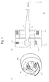
- a first embodiment of the present invention includes an MRI device 300 and a PET detector 210.
- the MRI device 300 has a measurement port (here, a patient port) 302.
- the PET detector 210 has an outer diameter smaller than the inner diameter of the patient port 302, and can move through the patient port 302 with a measurement object (here, a patient) 10.
- the PET detector 210 has an effective measurement field of view (referred to as a PET field of view) P wider than the effective measurement field of view (referred to as MRI field of view) M of the MRI device 300, thereby allowing MRI measurement during PET measurement.
- 24 denotes a cushion for protecting the patient 10
- 304 denotes an RF coil for the MRI device 300.
- the RF coil 304 may be integrated with the cushion 24 at the back side of the patient.
- the MRI field of view M is determined by the area where the static magnetic field is stable, which is typically 30 to 40 cm or so.
- the PET field of view P can be extended to improve the sensitivity of the PET measurement. A PET image of sufficient image quality can thus be obtained in a PET measurement time comparable to the MRI measurement time.
- the PET detector 210 is capable of stable operation in the MRI magnetic field environment.
- Examples include APD-bottomed scintillator blocks, and a Depth-of-Interaction (DOI) detectors having a three-dimensional array of semiconductor light receiving elements on the surface of a three-dimensional array of small scintillator elements, which has been proposed by the inventors in Japanese Patent Application Laid-Open No. 2009-121929 and in Y. Yazaki, H. Murayama, N. Inadama, A. Ohmura, H. Osada, F. Nishikido, K. Shibuya, T. Yamaya, E. Yoshida, T. Moriya, T. Yamashita, and H.
- DOI Depth-of-Interaction
- DOI detectors can be used to suppress a drop in resolution even in close proximity. The closer access can also reduce resolution degradation due to angular deviations, as well as increase the solid angle to improve the sensitivity even with a relatively small number of detectors.
- the PET detector 210 is integrated with a bed 20. That is, part of the PET detector 210 also functions as a bed. Since the PET detector can be brought closest to the patient, the solid angle increases for improved sensitivity and fast measurement.
- the RF coil 304 is installed so as to cover the PET field of view P and most of the axial field of view.
- the RF coil 304 is arranged inside (within the inner diameter of) the PET detector 210 since the closer the RF coil 304 is to the patient 10, the higher the signal S/N ratio becomes. Another reason is to prevent electrical noise and the like from the PET detector 210.
- the RF coil is highly transparent to annihilation radiations. The presence of the RF coil 304 thus has only a limited impact on the PET measurement.
- the bed 20 may be moved by a bed moving device 22 at constant speed or step by step.
- Fig. 4A shows the state at the start of the MRI measurement.
- Fig. 4B shows the state at the end of the MRI measurement.
- Tm is the MRI measurement time.
- Fig. 5A shows a procedure in which the PET measurement time Tp is maximized to increase the data collection time for improved PET image quality.
- Fig. 5B shows a procedure in which the PET measurement is started immediately before the start of the MRI measurement and ended immediately after the end of the MRI measurement, or PET data that is collected from immediately before the start of the MRI measurement to immediately after the end of the MRI measurement is used for PET image reconstruction processing.
- Such a procedure makes the PET measurement time and the MRI measurement time almost equal, thereby ensuring simultaneity between the PET measurement and the MRI measurement.
- the procedure of Fig. 5B is preferred.
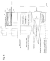
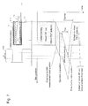
- Fig. 6 shows the time chart.
- the positions of the front and rear ends of the bed are plotted.
- the PET medicine has been administered to the patient in advance.
- FDG-PET it is typically administered an hour earlier.
- the maximum value Tpmax of the PET measurement time shows a difference in time between when the PET detector 210 is attached in place and when the PET detector 210 is detached or moved.
- Tp approaches Tpmax.
- Tp approaches Tm.
- the MRI measurement start position and the MRI measurement end portion need not necessarily be set at the respective ends of the MRI field of view M.
- the MRI measurement start position and the MRI measurement end position both may be at the center of the MRI field of view where a favorable magnetic field is formed.
- the bed may be slid step by step, not at constant speed.
- the MRI measurement is performed while the bed is moving on one way.
- the MRI measurement may be performed on both ways of the reciprocating movement.
- MRI measurement 1 onward and MRI measurement 2 on the return may be performed by the same sequence. Different sequences may be combined, for example, so that MRI measurement 1 is T1-weighted and MRI measurement 2 is T2-weighted.
- the PET detector 210 has a uniform configuration in the longitudinal direction of the measurement object, or the direction of the body axis of the patient 10 here.
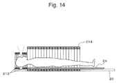
- the PET detector 210 may be divided into a head PET detector 212 and a trunk or body PET detector 214.
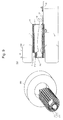
- Fig. 9B shows a sectional view of a concrete example of the second embodiment seen from a side.
- Figs. 10A and 10B show cross-sectional views of the body and head portions of the PET detector.
- the body PET detector has an elliptical cross section, whereas it may be circular.
- the head PET detector 212 and the body PET detector 214 are fixed to the bed 20 so that they can be horizontally moved with the patient 10 by the bed moving device 22.
- Coincidence measurement between the head PET detector 212 and the body PET detector 214 can prevent a drop in the accuracy of the reconstructed image near the border between the head PET detector 212 and the body PET detector 214.
- the head PET detector 212 and the body PET detector 214 may be spaced apart by using the technology of the open PET device that the inventors have proposed in WO 2009/133628 A1 .
- the PET field of view P equals to the head field of view H + the body field of view B.
- the RF coil may be a transmitter-receiver two-way coil, a transmitter coil, or a receiver coil.
- the RF coil and the PET detector may be formed as separate members. When the RF coil and the PET detector are integrated as shown in Figs. 10A and 10B , the following combinations are possible:
- Figs. 10A and 10B 218 denotes a cover, 312 denotes a head RF coil, and 314 denotes a body RF coil.
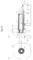
- Fig. 11A is a front view showing a concrete example of a third embodiment which is a modification of the second embodiment.
- Fig. 11B is a sectional view seen from a side.
- the head PET detector 212 is fixed to the bed 20.
- the body PET detector 214 can be horizontally moved by a PET detector moving device 220, independent of the bed 20.
- 320 designates rollers that support the PET detector 214 in the patient port 302.
- the head PET detector 212 and the body PET detector 214 have different center positions in the patient port 302 of the MRI device 300.
- the bed moving device 22 may include a bed up-down mechanism 26 so that the head PET detector 212 and the head RF coil 312 can be slid and moved up and down with the patient 10.
- the body PET detector 214 and the body RF coil 314 are only moved to slide horizontally, without up and down movements.
- the PET detector may be made of a combination of detectors of different resolutions depending on the locations.
- Fig. 12A shows a fourth embodiment in which high-resolution detectors are arranged in the vicinity of the head where high resolution is needed.
- Fig. 12B shows a fifth embodiment with a reduced number of detectors, in which the detectors are spaced wider, instead of the sensitivity being lowered, for the lower body or the legs in particular where not so high sensitivity is needed.
- the technology of the open PET device may be used to form an open area in the head PET device 212 in the vicinity of the field of view so as to alleviate the sense of confinement on the head.
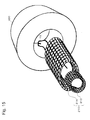
- the body PET detector 214 may be made of noncircular (in the diagram, elliptical) rings so that the PET detector comes closer to the patient's body.
- Figs. 16A to 16C show the configuration of essential parts where the detector rings can be changed in size according to the body type of the patient 10.
- Fig. 16A shows an example where normal-sized detector rings 214a are used.
- Fig. 16B shows an example where large-diametered detector rings 214b are used for the abdomen.
- Fig. 16C shows an example where the large-diametered detector rings 214b are used not only for the abdomen but for the entire body.
- Figs. 17A to 17C show the cross sections of Figs. 16A to 16C .
- Fig. 17A shows a PET detector layout for slender type
- Fig. 17B shows a PET detector layout for stout type
- Fig. 17C shows a PET detector layout for the head.
- the arched half portion of the detector on the bed side (lower side in the thickness direction) and that on the opposite side (upper side in the thickness direction) are arranged along the curves of respective different curvatures.
- the cells in the diagrams represent scintillator blocks or detector units.
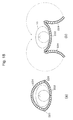
- an arched half PET detector 224 on the upper side in the thickness direction is openable, for example, in a double-door configuration so as to facilitate setting up the patient 10.
- 222 denotes the lower (bed-side) PET detector
- 226 denotes hinges.
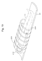
- the PET detector Since the PET detector is heavy in weight, it may be divided into several sections as shown in Fig. 19 (six sections in Fig. 19 ).
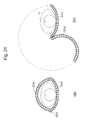
- the PET detector may be formed in a single-door configuration.
- the PET detector may be configured so that it is divided into an arched half detector 222 on the bed side (lower side in the thickness direction) and an arched half detector 224 on the opposite side (upper side in the thickness direction).
- arched half detector 222 on the bed side (lower side in the thickness direction)
- arched half detector 224 on the opposite side (upper side in the thickness direction).
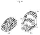
- Various sizes of upper detectors 224 may be provided according to the body type.
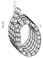
- detector units 204 may be connected into a belt-like configuration by links 232.
- the same belt-like PET detectors 230 can be used to form various sizes of detector rings according to the body type.
- the detector units 204 are fixed by fixing wires 234, for example.
- encoders 236 for acquiring angular information are attached to the joints of the detector units 204 on the upper side in the thickness direction.
- relative positions between the detector units 204 can thus be acquired to obtain a tomographic image by image reconstruction calculations.
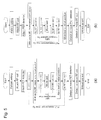
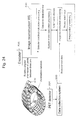
- Pairs of annihilation radiations detected by the PET detector 204 are processed into measurement data by a data collection system 500 through coincidence processing, data collection processing, etc.
- the measurement data is transmitted to the image reconstruction WS 400 for image reconstruction processing before output as a tomographic image.
- the image reconstruction needs accurate detector positions, or it is not possible to calculate the system matrix.
- the encoders 236 are then used to grasp the relationship in spatial position coordinates between the adjoining detector units, thereby grasping the positions of the respective detectors.
- the encoders 236 provide relative angular information on the joints between the detectors.
- the information is transmitted to the image reconstruction WS 400.
- the detector coordinates are initially determined by detector coordinate calculation processing.
- the system matrix is then calculated based on the detector coordinates.
- a whole system matrix calculated may be read at a time. Or, necessary system matrix elements may be calculated by on-the-fly processing when needed.
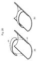
- Fig. 25A shows a case with small detector rings according to the tenth embodiment.
- Fig. 25B shows a case with large detector rings.
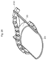
- large and small inner frames 30 attachable to the bed 20 may be prepared for respective body types. This makes it possible to accurately and easily grasp the spatial position coordinates (detector positions) of the belt-like PET detector 230 having no encoders such as shown in Fig. 27 .
- Such inner frames 30 are formed to have high rigidity as well as high transparency to radiation.
- the inner frames 30 are made of reinforced plastic.
- Fig. 28 shows the state where the belt-like PET detector 230 is being attached to an inner frame 30 according to the eleventh embodiment.
- Figs. 29A and 29B show attached states.
- Fig. 29A shows an example of small ring size
- Fig. 29B shows an example of large ring size.
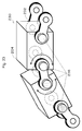
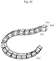
- the belt-like PET detector 230 may not only allow free rotations of the detector units 204, but also make the distances between the detector units 204 variable as in a twelfth embodiment shown in Fig. 30 .
- Fig. 31 shows the joints in detail.
- Fig. 32A shows the state of attachment of small ring size according to the twelfth embodiment.
- Fig. 32B shows the state of attachment of large ring size. Rings of different sizes can be formed by using the same number of detectors (in Figs. 32A and 32B , eight movable detector units) without redundant detectors as in Fig. 29A .
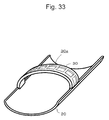
- positioning recesses 30a may be formed in the inner frame 30 so as to fix the detector positions.
- the system matrix may be calculated each time based on the detector coordinates. Since the types of the upper detectors 224 or inner frames 30 for use are limited, system matrices corresponding to the respective patterns of detector layout may be calculated in advance and stored into a storing device in the image reconstruction WS as a data set.
- the belt-like PET detectors may be used not only for the head and body, but also for some specific areas.
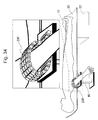
- Fig. 34 shows a thirteenth embodiment which shows another application example of the belt-like PET detectors.
- a belt-like PET detector 230 for arms is wound around the arm.
- the reference numeral 40 denotes a table on which the belt-like PET detector is placed.
- dynamic function measurement on the head using a head PET device (not shown in the diagram), is not easy to perform since arterial blood needs to be sampled at time intervals of several seconds to several minutes.
- the combined use of the head PET device and the belt-like PET detector wound around the arm can facilitate the dynamic function measurement since it is possible without arterial blood sampling to measure the concentration and flow rate of RI flowing through the arteries in the arm.
- the belt-like PET detector also allows area-specific high-precision diagnostic imaging. Examples of the area include the arms as well as the feet, joints, neck, and breast.
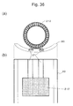
- the head PET detector 212 can be slid over guide rails 21 of the bed 20 in the direction of the body axis so as to facilitate setting up the patient 10.
- Fig. 36 shows the slide mechanism in detail.
- the head PET detector 212 may be detachable.
- the bed 20 and the PET detector 210 may be independently slidable when the PET field of view P lies between the field of view F of the RF coil and the MRI field of view M.
- the bed 20 and the PET detector 210 can be slid at different speeds so that a wider field of view corresponding to the width of the field of view F of the RF coil can be measured by PET and MRI.
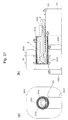
- the fifteenth embodiment has dealt with the case where the PET detector is integrated in the direction of the body axis.
- the head PET detector 212 and the body PET detector 214 may be separated from each other.
- the head PET detector 212 and the bed 20 are integrated with each other, and slide at a speed of Vb.
- the body PET detector 214 slides at a speed of Vp.
- the PET detector (or at least the body PET detector 214) may have a mechanism for making a movement independent of the movement of the bed 20.
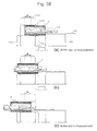
- the PET detector 214 can be moved into the MRI detector 300 for easy patient setup without a contrivance to open the PET detector.
- the PET detector 214 is moved into the MRI patient port 302 so that the patient 10 can easily get on the bed 20.
- the head PET detector 212 if used, is moved to the left in the diagram.
- the RF coils 312 and 314 and the head PET detector 212 are attached as shown in Fig. 41B .
- the head and body RF coils 312 and 314 are initially attached.
- the head PET detector 212 if used, is slid for attachment.
- the head RF coil 312 may be integrated with the head PET detector 212.
- the patient can be evacuated in order reverse to the foregoing.
- the MRI patient port 302 may be entered feet first.
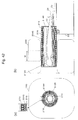
- a transmitter RF coil 304S may be integrally arranged inside the PET detector 210.
- a receiver RF coil is arranged closer to the patient.
- a head RF coil 312R and a body RF coil 314R of different sizes may be used.
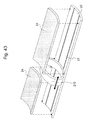
- Fig. 43 shows a nineteenth embodiment for measuring a local area, not the whole body, by PET and MRI at the same time.
- the PET detector 210 is slidable along the guide rails 21 on the bed 20, so that the PET detector 210 can be freely moved to the position of the area to measure.
- the PET detector 210 can be accurately and safely mounted on the measurement area when outside of the MRI patient port 302. Since the PET detector 210 mounted is slid with the patient on the bed 20, there is no danger of displacement.
- the difference in level between the bed 20 and the PET detector 210 is eliminated by the provision of cushions 24.
- the cushions 24 need to be adjusted in length depending on the position of the PET detector 210.
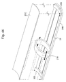
- Fig. 44 is a perspective view showing the configuration of essential parts of a twentieth embodiment which is a modification of the nineteenth embodiment.
- the bed 20 is composed of a base 20B which includes the guide rails 21, and supports 20S and a cover 20C.
- the PET detector 210 is arranged so that part of the ring is interposed between the base 20B and the cover 20C. Such a configuration eliminates a difference in level on the cover 20C which makes contact with the patient.
- the PET detector 210 can conveniently be slid to an appropriate position where to cover the measurement point with the patient put on the bed.
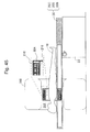
- Fig. 45 is a sectional view seen from a side, showing the overall configuration of the twentieth embodiment.
- the RF coil 304 is integrally arranged inside the PET detector 210.
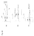
- Figs. 46A to 46C show the operating state of the twentieth embodiment.
- the bed is located away from the MRI patient port 302 and the PET detector 210 is moved to the bed end.
- the PET detector 210 is slid so that the measurement point (in the diagram, chest) is covered by the PET detector 210.
- the PET detector 210 is inserted into the MRI patient port 302 and the MRI measurement is started.
Landscapes
- Physics & Mathematics (AREA)
- Health & Medical Sciences (AREA)
- Nuclear Medicine, Radiotherapy & Molecular Imaging (AREA)
- General Physics & Mathematics (AREA)
- Engineering & Computer Science (AREA)
- General Health & Medical Sciences (AREA)
- Radiology & Medical Imaging (AREA)
- High Energy & Nuclear Physics (AREA)
- Condensed Matter Physics & Semiconductors (AREA)
- Pulmonology (AREA)
- Theoretical Computer Science (AREA)
- Life Sciences & Earth Sciences (AREA)
- Molecular Biology (AREA)
- Spectroscopy & Molecular Physics (AREA)
- Vascular Medicine (AREA)
- Signal Processing (AREA)
- Nuclear Medicine (AREA)
- Magnetic Resonance Imaging Apparatus (AREA)
Applications Claiming Priority (1)
| Application Number | Priority Date | Filing Date | Title |
|---|---|---|---|
| JP2010052389A JP5598956B2 (ja) | 2010-03-09 | 2010-03-09 | Pet/mri装置 |
Publications (2)
| Publication Number | Publication Date |
|---|---|
| EP2369358A2 true EP2369358A2 (de) | 2011-09-28 |
| EP2369358A3 EP2369358A3 (de) | 2012-01-04 |
Family
ID=43733182
Family Applications (1)
| Application Number | Title | Priority Date | Filing Date |
|---|---|---|---|
| EP10194990A Withdrawn EP2369358A3 (de) | 2010-03-09 | 2010-12-14 | PET/MRI-Vorrichtung, PET-Vorrichtung und System zur Bildrekonstruktion |
Country Status (3)
| Country | Link |
|---|---|
| US (3) | US20110224534A1 (de) |
| EP (1) | EP2369358A3 (de) |
| JP (1) | JP5598956B2 (de) |
Cited By (1)
| Publication number | Priority date | Publication date | Assignee | Title |
|---|---|---|---|---|
| EP2952931A1 (de) * | 2014-06-05 | 2015-12-09 | Beijing Top Grade- Kang Ming Medical Device Inc. | Kopfspule für ein mri/pet-bildgebungssystem |
Families Citing this family (25)
| Publication number | Priority date | Publication date | Assignee | Title |
|---|---|---|---|---|
| JP5598956B2 (ja) * | 2010-03-09 | 2014-10-01 | 独立行政法人放射線医学総合研究所 | Pet/mri装置 |
| JP5789861B2 (ja) | 2010-11-01 | 2015-10-07 | 国立研究開発法人放射線医学総合研究所 | Pet−mri装置 |
| WO2013161910A1 (ja) | 2012-04-24 | 2013-10-31 | 株式会社東芝 | Pet-mri装置 |
| WO2013161907A1 (ja) * | 2012-04-24 | 2013-10-31 | 株式会社東芝 | 医用画像診断装置 |
| WO2013161911A1 (ja) | 2012-04-24 | 2013-10-31 | 株式会社東芝 | 医用画像診断装置及びpet-mri装置 |
| JP2013228226A (ja) * | 2012-04-24 | 2013-11-07 | Toshiba Corp | Pet−mri装置 |
| JP6010815B2 (ja) * | 2012-04-27 | 2016-10-19 | 国立研究開発法人量子科学技術研究開発機構 | 楕円軌道回転装置及びpet装置 |
| US9554707B2 (en) | 2012-06-29 | 2017-01-31 | General Electric Company | Concurrent acquisition of PET fields during acquisition of a MRI field of view |
| WO2014026837A1 (en) * | 2012-08-14 | 2014-02-20 | Koninklijke Philips N.V. | Patient bed with magnetic resonance radio frequency antenna, particularly for use in a magnetic resonance imaging guided therapy system |
| US10634747B2 (en) * | 2013-03-14 | 2020-04-28 | West Virginia University | Apparatus and implementation method of a set of universal compact portable MR-compatible PET inserts to convert whole-body MRI scanners into organ-specific hybrid PET/MRI imagers |
| DE102013215902B4 (de) * | 2013-08-12 | 2017-02-09 | Siemens Healthcare Gmbh | Magnetresonanzanlage mit optimierter Anordnung von Lokalspulen |
| JP6124216B2 (ja) | 2013-10-30 | 2017-05-10 | 国立研究開発法人量子科学技術研究開発機構 | ヘルメット型pet装置 |
| KR101600883B1 (ko) | 2013-12-12 | 2016-03-10 | 삼성전자주식회사 | Rf 코일 및 이를 포함하는 자기공명영상장치 |
| US9737274B2 (en) | 2013-12-17 | 2017-08-22 | Mediso Orvosi Berendezes Fejleszto es Szerviz Kft. | Tomographic apparatus |
| US20160058401A1 (en) * | 2014-08-29 | 2016-03-03 | Siemens Medical Solutions Usa, Inc. | MR-PET Hybrid Scout Scan/Topogram Workflow |
| US10018696B2 (en) | 2016-07-11 | 2018-07-10 | Siemens Medical Solutions Usa, Inc. | Magnetic lensing for beta emission imaging |
| JP6425756B2 (ja) * | 2017-03-24 | 2018-11-21 | 国立研究開発法人量子科学技術研究開発機構 | ヘルメット型pet装置 |
| EP3583981B1 (de) * | 2017-05-12 | 2020-12-23 | Neuboron Medtech Ltd. | Photonenemissionsdetektor und borneutroneneinfangtherapiesystem damit |
| CN107080551B (zh) * | 2017-05-25 | 2023-08-22 | 苏州瑞派宁科技有限公司 | 一种三维异质pet系统 |
| US20190328270A1 (en) * | 2018-04-30 | 2019-10-31 | Global Diagnostic Imaging Solutions, LLC | Mri patient safety positioning assembly |
| CN109009197B (zh) * | 2018-08-06 | 2020-07-07 | 南京航空航天大学 | 一种用于pet检测的双晶体条穿越符合响应线检测系统和方法 |
| EP4058817A4 (de) * | 2019-11-13 | 2023-12-20 | Sino Canada Health Institute Inc. | Brainpet-system zur simultanen mrt- und pet-bildgebung |
| CZ33814U1 (cs) * | 2020-01-13 | 2020-02-27 | Advacam S.R.O. | Modulární gama kamera a sestava modulárních gama kamer |
| CN112932513A (zh) * | 2021-01-27 | 2021-06-11 | 北京科技大学 | 一种医学成像系统 |
| CN113081016A (zh) * | 2021-03-26 | 2021-07-09 | 北京科技大学 | 一种全身pet成像系统 |
Citations (5)
| Publication number | Priority date | Publication date | Assignee | Title |
|---|---|---|---|---|
| US20080287772A1 (en) | 2007-05-18 | 2008-11-20 | Siemens Medical Solutions Usa, Inc. | Motion Compensation in PET Reconstruction |
| US20090108206A1 (en) | 2007-10-29 | 2009-04-30 | Siemens Medical Solutions Usa, Inc. | MR-Compatible Blood Sampling System For PET Imaging Applications in Combined PET/MR Imaging System |
| JP2009121929A (ja) | 2007-11-14 | 2009-06-04 | Hamamatsu Photonics Kk | 放射線位置検出器 |
| WO2009133628A1 (ja) | 2008-05-02 | 2009-11-05 | 独立行政法人放射線医学総合研究所 | 開放型pet装置 |
| US7626392B2 (en) | 2007-08-24 | 2009-12-01 | Siemens Aktiengesellschaft | Antenna unit for a PET/MRI scanner |
Family Cites Families (47)
| Publication number | Priority date | Publication date | Assignee | Title |
|---|---|---|---|---|
| JP4445055B2 (ja) * | 1999-01-21 | 2010-04-07 | 株式会社東芝 | 核医学診断装置 |
| US20040195512A1 (en) * | 2000-05-16 | 2004-10-07 | Crosetto Dario B. | Method and apparatus for anatomical and functional medical imaging |
| US6754520B2 (en) * | 2001-10-19 | 2004-06-22 | Koninklijke Philips Electronics N.V. | Multimodality medical imaging system and method with patient handling assembly |
| US7262415B2 (en) * | 2002-06-02 | 2007-08-28 | Crosetto Dario B | Gantry for geometrically configurable and non-configurable positron emission tomography detector arrays |
| US20050020898A1 (en) * | 2003-07-10 | 2005-01-27 | Vosniak Kenneth J. | System and method for configuring a scanning procedure |
| JP2005058428A (ja) * | 2003-08-11 | 2005-03-10 | Hitachi Ltd | 病巣位置特定システム及び放射線検査装置 |
| US7937131B2 (en) * | 2004-09-06 | 2011-05-03 | Gachon University Of Medicine & Science Industry-Academic Cooperation Foundation | PET—MRI hybrid apparatus and method of implementing the same |
| CN100574701C (zh) * | 2004-09-06 | 2009-12-30 | 株式会社日立医药 | 磁共振成像装置和方法 |
| US8423125B2 (en) * | 2004-11-09 | 2013-04-16 | Spectrum Dynamics Llc | Radioimaging |
| WO2006071922A2 (en) * | 2004-12-29 | 2006-07-06 | Siemens Medical Solutions Usa, Inc. | Combined pet/mr imaging system and apd-bassed pet detector for use in simultaneous pet/mr imaging |
| US7750311B2 (en) * | 2005-02-25 | 2010-07-06 | Intramedical Imaging, Llc | Positron emission detectors and configurations |
| JP5100374B2 (ja) * | 2005-04-26 | 2012-12-19 | 株式会社日立メディコ | 磁気共鳴イメージング装置および方法 |
| WO2006119085A2 (en) * | 2005-04-29 | 2006-11-09 | The Regents Of The University Of California | Integrated pet-mri scanner |
| US7640607B2 (en) * | 2005-04-29 | 2010-01-05 | Varian Medical Systems, Inc. | Patient support systems |
| DE102005040107B3 (de) * | 2005-08-24 | 2007-05-31 | Siemens Ag | Kombiniertes PET-MRT-Gerät und Verfahren zur gleichzeitigen Aufnahme von PET-Bildern und MR-Bildern |
| US7467008B2 (en) * | 2005-09-30 | 2008-12-16 | Siemens Medical Solutions Usa, Inc. | Ectography multimodality imaging system for diagnosis and treatment |
| DE102005048853A1 (de) * | 2005-10-12 | 2007-04-26 | Siemens Ag | Bildgebende medizinische Modalität |
| JP2007163373A (ja) * | 2005-12-15 | 2007-06-28 | Shimadzu Corp | 核医学診断装置 |
| US20070238950A1 (en) * | 2006-03-24 | 2007-10-11 | Vija A H | Separate and combined multi-modality diagnostic imaging system |
| US8295905B2 (en) * | 2006-06-20 | 2012-10-23 | Imris Inc. | Movable integrated scanner for surgical imaging applications |
| DE102006036572B4 (de) * | 2006-08-04 | 2014-10-16 | Siemens Aktiengesellschaft | Vorrichtung zur überlagerten MRI- und PET-Bilddarstellung |
| DE102006046287A1 (de) * | 2006-09-29 | 2008-04-03 | Siemens Ag | Felderzeugungseinheit einer kombinierten MR-PET-Anlage |
| JP4370420B2 (ja) * | 2006-10-02 | 2009-11-25 | 株式会社日立メディコ | ガンマカメラシステム |
| US20080146914A1 (en) * | 2006-12-19 | 2008-06-19 | General Electric Company | System, method and apparatus for cancer imaging |
| US7847552B2 (en) * | 2007-01-10 | 2010-12-07 | General Electric Company | Exclusion of compromised PET data during simultaneous PET-MR acquisition |
| CN101583310B (zh) * | 2007-01-11 | 2013-09-04 | 皇家飞利浦电子股份有限公司 | 用于同时进行pet和mr成像的pet/mr扫描器 |
| US7759647B2 (en) * | 2007-01-24 | 2010-07-20 | Siemens Medical Solutions Usa, Inc. | PET imaging system with APD-based PET detectors and three-dimensional positron-confining magnetic field |
| JP5176355B2 (ja) | 2007-03-22 | 2013-04-03 | 株式会社島津製作所 | 診断装置 |
| EP2138866B1 (de) * | 2007-04-17 | 2019-03-06 | National Institutes for Quantum and Radiological Science and Technology | Pet-einrichtung und verfahren zur rekonstitution eines bildes dieser |
| US7768261B2 (en) * | 2007-04-27 | 2010-08-03 | Siemens Medical Solutions Usa, Inc. | Apparatus and method for image alignment for combined positron emission tomography (PET) and magnetic resonance imaging (MRI) scanner |
| DE102007023657B4 (de) * | 2007-05-22 | 2014-03-20 | Siemens Aktiengesellschaft | Verfahren zur Datenaufnahme bei einer funktionellen Gehirnuntersuchung mit einem kombinierten Magnetresonanz-PET-Gerät |
| JP2008307083A (ja) * | 2007-06-12 | 2008-12-25 | Shimadzu Corp | 医用画像診断装置 |
| DE102007029363A1 (de) * | 2007-06-26 | 2009-01-08 | Siemens Ag | Kombinierte Positronenemissions-Magnetresonanz-Tomographie-Vorrichtung |
| DE102007031930A1 (de) * | 2007-07-09 | 2009-01-29 | Siemens Ag | Verfahren und Vorrichtung zum bildlichen Darstellen von funktionellen Vorgängen im Gehirn |
| CN101765790B (zh) * | 2007-07-25 | 2013-02-13 | 皇家飞利浦电子股份有限公司 | Mr/pet成像系统 |
| JP5262152B2 (ja) * | 2008-02-06 | 2013-08-14 | 株式会社島津製作所 | 診断システム |
| JP2009236726A (ja) * | 2008-03-27 | 2009-10-15 | Shimadzu Corp | 陽電子放出型断層撮影装置 |
| CN101990643B (zh) * | 2008-04-10 | 2014-09-03 | 皇家飞利浦电子股份有限公司 | 模块化多几何结构pet系统 |
| JP5046143B2 (ja) * | 2008-04-14 | 2012-10-10 | 独立行政法人放射線医学総合研究所 | Pet装置及び検出器の配置決定方法 |
| DE102009023806B4 (de) * | 2008-07-09 | 2011-04-28 | Siemens Aktiengesellschaft | Kombinierte PET-MR-Einrichtung, Bauteil und Lokalspule |
| KR101031483B1 (ko) * | 2009-02-24 | 2011-04-26 | 성균관대학교산학협력단 | Pet-mri 융합시스템 |
| JP5619448B2 (ja) * | 2009-08-20 | 2014-11-05 | 株式会社東芝 | 磁気共鳴イメージング装置 |
| US8731634B2 (en) * | 2009-10-20 | 2014-05-20 | General Electric Company | Medical imaging system and patient positioning system including a movable transport belt |
| JP5598956B2 (ja) * | 2010-03-09 | 2014-10-01 | 独立行政法人放射線医学総合研究所 | Pet/mri装置 |
| KR20120022356A (ko) * | 2010-09-02 | 2012-03-12 | 한국과학기술원 | Pet-mri 융합 시스템 |
| JP5750685B2 (ja) * | 2011-01-11 | 2015-07-22 | 国立研究開発法人放射線医学総合研究所 | Pet装置及びpet−mri装置 |
| US9494664B2 (en) * | 2012-05-21 | 2016-11-15 | General Electric Company | Neck coil arrangements for magnetic resonance imaging |
-
2010
- 2010-03-09 JP JP2010052389A patent/JP5598956B2/ja not_active Expired - Fee Related
- 2010-12-03 US US12/959,893 patent/US20110224534A1/en not_active Abandoned
- 2010-12-14 EP EP10194990A patent/EP2369358A3/de not_active Withdrawn
-
2013
- 2013-10-23 US US14/061,143 patent/US20140135613A1/en not_active Abandoned
-
2017
- 2017-01-11 US US15/403,657 patent/US10627466B2/en not_active Expired - Fee Related
Patent Citations (5)
| Publication number | Priority date | Publication date | Assignee | Title |
|---|---|---|---|---|
| US20080287772A1 (en) | 2007-05-18 | 2008-11-20 | Siemens Medical Solutions Usa, Inc. | Motion Compensation in PET Reconstruction |
| US7626392B2 (en) | 2007-08-24 | 2009-12-01 | Siemens Aktiengesellschaft | Antenna unit for a PET/MRI scanner |
| US20090108206A1 (en) | 2007-10-29 | 2009-04-30 | Siemens Medical Solutions Usa, Inc. | MR-Compatible Blood Sampling System For PET Imaging Applications in Combined PET/MR Imaging System |
| JP2009121929A (ja) | 2007-11-14 | 2009-06-04 | Hamamatsu Photonics Kk | 放射線位置検出器 |
| WO2009133628A1 (ja) | 2008-05-02 | 2009-11-05 | 独立行政法人放射線医学総合研究所 | 開放型pet装置 |
Non-Patent Citations (4)
| Title |
|---|
| JUDENHOFER MS ET AL.: "Simultaneous PET-MRI: a new approach for functional and morphological imaging", NET MED, vol. 14, no. 4, 2008, pages 459 - 65 |
| SCHLEMMER HW ET AL.: "Simultaneous MR/PET Imaging of the Human Brain: Feasibility Study", RADIOLOGY, vol. 248, 2008, pages 1028 - 1035 |
| SCHLYER D ET AL.: "A Simultaneous PET/MRI scanner based on RatCAP in small animals", IEEE NUCLEAR SCIENCE SYMPOSIUM CONFERENCE RECORD, vol. 5, 2007, pages 3256 - 3259 |
| Y. YAZAKI; H. MURAYAMA; N. INADAMA; A. OHMURA; H. OSADA; F. NI- SHIKIDO; K. SHIBUYA; T. YAMAYA; E. YOSHIDA; T. MORIYA: "Preliminary study on a new DOI PET detector with limited number of photo-detectors", JOINT MEETING ON MEDICAL PHYSICS, 10 September 2008 (2008-09-10) |
Cited By (1)
| Publication number | Priority date | Publication date | Assignee | Title |
|---|---|---|---|---|
| EP2952931A1 (de) * | 2014-06-05 | 2015-12-09 | Beijing Top Grade- Kang Ming Medical Device Inc. | Kopfspule für ein mri/pet-bildgebungssystem |
Also Published As
| Publication number | Publication date |
|---|---|
| US20140135613A1 (en) | 2014-05-15 |
| US10627466B2 (en) | 2020-04-21 |
| EP2369358A3 (de) | 2012-01-04 |
| JP2011185796A (ja) | 2011-09-22 |
| JP5598956B2 (ja) | 2014-10-01 |
| US20110224534A1 (en) | 2011-09-15 |
| US20170168127A1 (en) | 2017-06-15 |
Similar Documents
| Publication | Publication Date | Title |
|---|---|---|
| US10627466B2 (en) | PET/MRI device, PET device, and image reconstruction system | |
| Zaidi et al. | An outlook on future design of hybrid PET/MRI systems | |
| US9029787B2 (en) | Multi-purpose PET device | |
| US7937131B2 (en) | PET—MRI hybrid apparatus and method of implementing the same | |
| US20080135769A1 (en) | Attenuation correction of pet image using image data acquired with an mri system | |
| CN101390754B (zh) | 用于确定患者的正电子发射断层造影数据的衰减值的方法 | |
| Jung et al. | PET/MRI: technical challenges and recent advances | |
| EP2424429B1 (de) | Vorrichtung für dreidimensionale anatomische und funktionelle bildgebung sowie verfahren dafür | |
| EP3323001B1 (de) | Mobiler tof-pet-einsatz | |
| CN103260522A (zh) | 用于ct-mri和核混合成像、交叉校准以及性能评估的设备 | |
| CN103153190A (zh) | 多模态紧凑型膛成像系统 | |
| US20130030287A1 (en) | Proximity imaging type pet apparatus and system | |
| Shah et al. | Hybrid PET/MR imaging: physics and technical considerations | |
| US10080534B2 (en) | Medical image diagnostic device | |
| JP5939549B2 (ja) | Pet装置 | |
| CN210903068U (zh) | 一种pet检测设备 | |
| US20080319305A1 (en) | Method for determining at least one pet parameter | |
| KR101051051B1 (ko) | 자기공명영상촬영기와 양전자방출단층촬영기의 융합 시스템에 사용되는 양전자방출단층촬영기의 가동장치 | |
| US20140221817A1 (en) | Method for generating attenuation correction for a combined magnetic resonance-positron emission tomography device | |
| CN111316327B (zh) | 对移动对象的pet数据的衰减校正 | |
| Beyer et al. | MR/PET–hybrid imaging for the next decade | |
| KR101392132B1 (ko) | Mri-pet-ct 하이브리드 이미징 시스템 및 방법 | |
| CN119523517B (zh) | 长轴pet系统灵敏度测量方法、系统、电子设备和存储介质 | |
| Gebhardt et al. | Initial results of the Hyperion II D PET insert for simultaneous PET-MRI applied to atherosclerotic plaque imaging in New-Zealand white rabbits | |
| Wagenaar et al. | A stationary SPECT system for simultaneous MRI/SPECT dual-modality pre-clinical imaging |
Legal Events
| Date | Code | Title | Description |
|---|---|---|---|
| PUAI | Public reference made under article 153(3) epc to a published international application that has entered the european phase |
Free format text: ORIGINAL CODE: 0009012 |
|
| AK | Designated contracting states |
Kind code of ref document: A2 Designated state(s): AL AT BE BG CH CY CZ DE DK EE ES FI FR GB GR HR HU IE IS IT LI LT LU LV MC MK MT NL NO PL PT RO RS SE SI SK SM TR |
|
| AX | Request for extension of the european patent |
Extension state: BA ME |
|
| PUAL | Search report despatched |
Free format text: ORIGINAL CODE: 0009013 |
|
| AK | Designated contracting states |
Kind code of ref document: A3 Designated state(s): AL AT BE BG CH CY CZ DE DK EE ES FI FR GB GR HR HU IE IS IT LI LT LU LV MC MK MT NL NO PL PT RO RS SE SI SK SM TR |
|
| AX | Request for extension of the european patent |
Extension state: BA ME |
|
| RIC1 | Information provided on ipc code assigned before grant |
Ipc: G01R 33/48 20060101AFI20111128BHEP |
|
| 17P | Request for examination filed |
Effective date: 20120704 |
|
| 17Q | First examination report despatched |
Effective date: 20151120 |
|
| STAA | Information on the status of an ep patent application or granted ep patent |
Free format text: STATUS: THE APPLICATION IS DEEMED TO BE WITHDRAWN |
|
| 18D | Application deemed to be withdrawn |
Effective date: 20160401 |