EP2369757A2 - Procédé de formation de faisceau et appareil pour utiliser un schéma de division de débit dans un canal d'interférence à plusieurs cellules et plusieurs antennes - Google Patents
Procédé de formation de faisceau et appareil pour utiliser un schéma de division de débit dans un canal d'interférence à plusieurs cellules et plusieurs antennes Download PDFInfo
- Publication number
- EP2369757A2 EP2369757A2 EP11151254A EP11151254A EP2369757A2 EP 2369757 A2 EP2369757 A2 EP 2369757A2 EP 11151254 A EP11151254 A EP 11151254A EP 11151254 A EP11151254 A EP 11151254A EP 2369757 A2 EP2369757 A2 EP 2369757A2
- Authority
- EP
- European Patent Office
- Prior art keywords
- receiver
- stream
- target
- transmitter
- reception
- Prior art date
- Legal status (The legal status is an assumption and is not a legal conclusion. Google has not performed a legal analysis and makes no representation as to the accuracy of the status listed.)
- Granted
Links
Images



Classifications
-
- H—ELECTRICITY
- H04—ELECTRIC COMMUNICATION TECHNIQUE
- H04B—TRANSMISSION
- H04B7/00—Radio transmission systems, i.e. using radiation field
- H04B7/02—Diversity systems; Multi-antenna system, i.e. transmission or reception using multiple antennas
- H04B7/04—Diversity systems; Multi-antenna system, i.e. transmission or reception using multiple antennas using two or more spaced independent antennas
- H04B7/06—Diversity systems; Multi-antenna system, i.e. transmission or reception using multiple antennas using two or more spaced independent antennas at the transmitting station
- H04B7/0613—Diversity systems; Multi-antenna system, i.e. transmission or reception using multiple antennas using two or more spaced independent antennas at the transmitting station using simultaneous transmission
- H04B7/0615—Diversity systems; Multi-antenna system, i.e. transmission or reception using multiple antennas using two or more spaced independent antennas at the transmitting station using simultaneous transmission of weighted versions of same signal
- H04B7/0617—Diversity systems; Multi-antenna system, i.e. transmission or reception using multiple antennas using two or more spaced independent antennas at the transmitting station using simultaneous transmission of weighted versions of same signal for beam forming
-
- H—ELECTRICITY
- H04—ELECTRIC COMMUNICATION TECHNIQUE
- H04B—TRANSMISSION
- H04B7/00—Radio transmission systems, i.e. using radiation field
- H04B7/02—Diversity systems; Multi-antenna system, i.e. transmission or reception using multiple antennas
- H04B7/04—Diversity systems; Multi-antenna system, i.e. transmission or reception using multiple antennas using two or more spaced independent antennas
- H04B7/0413—MIMO systems
- H04B7/0426—Power distribution
- H04B7/0434—Power distribution using multiple eigenmodes
-
- H—ELECTRICITY
- H04—ELECTRIC COMMUNICATION TECHNIQUE
- H04B—TRANSMISSION
- H04B7/00—Radio transmission systems, i.e. using radiation field
- H04B7/02—Diversity systems; Multi-antenna system, i.e. transmission or reception using multiple antennas
- H04B7/04—Diversity systems; Multi-antenna system, i.e. transmission or reception using multiple antennas using two or more spaced independent antennas
- H04B7/0413—MIMO systems
- H04B7/0452—Multi-user MIMO systems
-
- H—ELECTRICITY
- H04—ELECTRIC COMMUNICATION TECHNIQUE
- H04W—WIRELESS COMMUNICATION NETWORKS
- H04W72/00—Local resource management
- H04W72/04—Wireless resource allocation
- H04W72/044—Wireless resource allocation based on the type of the allocated resource
- H04W72/0453—Resources in frequency domain, e.g. a carrier in FDMA
Definitions
- the target transmitter may further include that the rate splitting encoder is further configured to encode the first stream and the second stream to enable a neighbor receiver corresponding to the neighbor transmitter to decode: a common message of the first stream received in a first reception spatial dimension of the neighbor receiver; and a common message of the second stream received in a second reception spatial dimension of the neighbor receiver.
- a method of allocating a frequency resource for a multi-cell communication system comprising a first cell, a second cell, and a third cell, the method comprising: allocating the same inner frequency resource to inner-cells of: the first cell; the second cell; and the third cell; and allocating: a first frequency resource to an outer-cell of the first cell; a second frequency resource to an outer-cell of the second cell; and a third frequency resource to an outer cell of the third cell, wherein the first frequency resource, the second frequency resource, and the third frequency resource partially overlap each other.
- a computer-readable storage medium having stored therein program instructions to cause a processor to execute method of a target transmitter corresponding to a target receiver, the method comprising: encoding a first stream and a second stream for transmission to the target receiver according to a rate splitting scheme; and using transmission beamforming vectors to align the first stream, as interference, in a second reception spatial dimension of the target receiver and in a second reception spatial dimension of a neighbor receiver, and to align the second stream, as interference, in a first reception spatial dimension of the target receiver and in the first reception spatial dimension of the neighbor receiver.
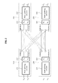
- FIG. 1 illustrates an example of a communication system that applies a rate splitting scheme to a single transmission and a single reception antenna interference channel.
- the transmitter (1) 110 and the transmitter (2) 130 may separate a message to be transmitted into a common message and a private message.
- the transmitter may transmit the common message and the private message to a receiver.
- message features such as an amplitude of the common message and the private message, a rate of the common message and the private message, and the like, may be adaptively adjusted based on channels between the transmitter (1) 110, the transmitter (2) 130, the receiver (1) 120, and the receiver (2) 140.
- the messages features may be adjusted based on the strength of the signal channels and the strength of the interference channels.
- the common message may be decodable by both a corresponding receiver and one or more neighboring receivers.
- the rate or the transmission power of the common message of the transmitter (1) 110 may be adjusted such that both the transmitter (1) 120 and the receiver (2) 140 may decode the common message.
- the receiver (2) 140 may decode the common message of the transmitter (1) 110 and may remove, from a received signal, a component corresponding to the common message of the transmitter (1) 110.
- the common message of the transmitter (1) 110 may be interference to the receiver (2) 140. Accordingly, the receiver (2) 140 may remove the interference thereby improving the reception quality of the receiver (2) 140.
- the receiver (2) 140 may receive the message 111 via a channel 12 and may receive the message 131 via a channel 22.
- the receiver (2) 140 may receive messages C 1 , P 1 , C 2 , and P 2 , where messages C 1 and P 1 act as interference to the receiver (2) 140.
- the receiver (2) 140 may decode C 1 , C 2 , and P 2 and may remove interference due to C 1 . Accordingly, only P 1 may remain in the receiver (2) 140 as interference.
- a received signal y1 of the first receiver 220 and a received signal y2 of the second receiver 240 may be expressed as shown in Equation 2.
- y 1 H 11 ⁇ V 1 ⁇ s 1 + H 11 ⁇ V 1 ⁇ s 2 + H 12 ⁇ V 3 ⁇ s 3 + H 12 ⁇ V 4 ⁇ s 4 + n 1
- y 2 H 22 ⁇ V 3 ⁇ s 3 + H 22 ⁇ V 4 ⁇ s 4 + H 21 ⁇ V 1 ⁇ s 1 + H 21 ⁇ V 2 ⁇ s 2 + n 2
- H j,i corresponds to a channel matrix from an i th transmitter to j th receiver
- n j corresponds to an Additive White Gaussian Noise (AWGN) of the j th receiver.
- the j th receiver may obtain an effective signal by multiplying y j by a reception beamforming vector w H j .
- symbols S 1 and S 3 may be aligned in one of two spatial dimensions of the first receiver 220, and symbols S 2 and S 4 transmitted via different channels may be aligned in the other dimension of the first receiver 220.
- the symbols S 1 and S 3 may be aligned in one of two spatial dimensions of the second receiver 240, and the symbols S 2 and S 4 may be aligned in the other dimension of the second receiver 240.
- Equation 3 For the alignment of symbols S 1 , S 2 , S 3 , and S 4 , the following condition as shown in Equation 3 may be used.
- span w 1 span H 11 ⁇ v 1 H 12 ⁇ v 3
- span w 2 span H 11 ⁇ v 2 H 12 ⁇ v 4
- Transmission beamforming vectors V 1 , V 2 , V 3 and V 4 and reception beamforming vectors W 1 , W 2 , W 3 , and W 4 are unit vectors. Accordingly, a condition as shown in Equation 4 may be additionally used.
- Equation 5 A decoding condition of the first receiver 220 and the second receiver 240 expressed in Equation 5 may be rewritten as the condition shown in Equation 6.
- r 1 c 1 ⁇ w 1 + c 2 ⁇ w 2
- r 2 c 3 ⁇ w 3 + c 4 ⁇ w 4
- Equation 6 r i corresponds to a 2 x 1 random column vector, and c i corresponds to a complex parameter.
- a unified system equation including the conditions may be expressed as shown in Equation 7.
- the conditions may include, for example, an interference alignment condition and a condition enabling the first receiver 220 and the second receiver 240 to decode a desired signal, ⁇ 1 ⁇ I N 0 N ⁇ N 0 N ⁇ N 0 N ⁇ N - H 11 0 N ⁇ M 0 N ⁇ M 0 N ⁇ M ⁇ 2 ⁇ I N 0 N ⁇ N 0 N ⁇ N 0 N ⁇ N 0 N ⁇ M 0 N ⁇ M - H 12 0 N ⁇ M 0 N ⁇ N ⁇ 3 ⁇ I N 0 N ⁇ N 0 N ⁇ N 0 N ⁇ M - H 11 0 N ⁇ M 0 N ⁇ M 0 N ⁇ N ⁇ 4 ⁇ I N 0 N ⁇ N 0 N ⁇ N 0 N ⁇ M ⁇ M ⁇ M 0 N ⁇ M 0 N ⁇ M 0 N ⁇ M
- M corresponds to the number of antennas of each transmitter
- N corresponds to the number of antennas of each receiver
- K corresponds to the number of transmitters.
- Equation 7 may have at least one value that exists according to Bezout's theory. Accordingly, the value of Equation 7, for example, V 1 , V 2 , V 3 , and V 4 and W 1 , W 2 , W 3 , and W 4 may be generally obtained based on a Newton's method.
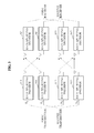
- two single-input single-output (SISO) interference channels may be generated as illustrated in FIG. 3 .
- the rate splitting encoder 311 of the first transmitter and the rate splitting encoder 331 of the second transmitter may be established after transmission and reception beamforming is performed.
- the rate splitting encoder 311 of the first transmitter may correspond to the rate splitting decoder 321 of the first receiver
- the rate splitting encoder 331 of the second transmitter may correspond to the rate splitting decoder 341 of the second receiver.
- the rate splitting encoder 312 of the first transmitter and the rate splitting encoder 322 of the second transmitter may correspond to the rate splitting decoder 322 of the first receiver and the rate splitting decoder 342 of the second receiver.
- the two streams of different transmitters or receivers may be established, and thus, a rate splitting scheme may be applied.
- the rate splitting decoder 321 of the first receiver may receive symbols S 1 and S 3 , and may decode symbol S 1 and a common message of symbol S 3 . Accordingly, interference from the common message of S 3 may be removed, and a component corresponding to a private message of S 3 may remain as interference.
- the rate splitting decoder 341 of the second receiver may receive symbols S 1 and S 3 , and may decode symbol S 3 and a common message of symbol S 1 . Accordingly, interference due to the common message of S 1 may be removed and a component corresponding to a private message of S 1 may remain as interference. Similarly, interference in a pair of S 2 and S 4 may be reduced.
- the rate splitting scheme may be used after the transmission beamforming and the reception beamforming are performed.
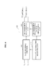
- FIG. 4 illustrates a first transmitter of a beamforming communication system using a rate splitting scheme in a multi-cell multi-antenna interference channel.
- the first transmitter includes a channel information receiving unit 410, a rate splitting encoder 420, a transmission beamforming vector generating unit 430, and a transmission beamforming unit 440.
- the rate splitting encoder 420 may encode symbols S 1 and S 2 , for example, streams to be received by a first receiver, based on the rate splitting scheme.
- the rate splitting encoder 420 may receive, from the channel information receiving unit 410, channel information including amplitude of a signal and amplitude of interference.
- the transmission beamforming unit 440 may perform transmission beamforming to align S 1 as interference in a second reception spatial dimension of the first receiver and in a second reception spatial dimension of the second receiver, and to align S 2 as interference in a first reception spatial dimension of the first receiver and in a first reception spatial dimension of the second receiver.
- the transmission beamforming unit 440 may perform beamforming based on channel information between the first transmitter and the first receiver and/or channel information between the first transmitter and the second receiver.
- the transmission beamforming unit 440 may perform beamforming based on channel information between the second transmitter and the first receiver and/or channel information between the second transmitter and the second receiver.
- the transmission beamforming vector generating unit 430 may generate a transmission beamforming vector based on the channel information.
- the transmission beamforming vector generating unit 430 may receive channel information from the channel information receiving unit 410.
- the transmission beamforming vector generating unit 430 may generate transmission beamforming vectors based on reception beamforming vectors of the first receiver and reception beamforming vectors of the second receiver which may be linearly independent.
- the first transmitter may indirectly generate the transmission beamforming vectors, and may receive information associated with the transmission beamforming vectors to perform beamforming.
- FIG. 5 illustrates a first receiver of a beamforming communication system using a rate splitting scheme in the multi-cell multi-antenna interference channel.
- the first receiver includes an antenna a, an antenna b, a channel information estimating unit 510, a reception beamforming vector generating unit 520, a reception beamforming unit 530, and a rate splitting decoder 540.
- S 1 and S 2 may be transmitted by a first transmitter corresponding to the first receiver
- S 3 and S 4 may be transmitted by a second transmitter which is a neighbor transmitter of the first transmitter.
- the reception beamforming unit 530 may perform beamforming using reception beamforming vectors to remove components associated with S 2 and S 4 from a signal received by the first receiver in a first reception spatial dimension.
- the reception beamforming unit 530 may perform beamforming using reception beamforming vectors to remove components associated with S 1 and S 3 from a signal received by the first receiver, in a second reception spatial dimension.
- the reception beamforming unit 530 may perform beamforming based on channel information between the first transmitter and the first receiver and/or based on channel information between second transmitter and the first receiver.
- the reception beamforming unit 530 may perform beamforming based on channel information between the first transmitter and a second receiver and/or based on channel information between the second transmitter and the second receiver.
- the channel information may be used when the reception beamforming vector generating unit 520 generates reception beamforming vectors.
- the reception beamforming vector generating unit 520 may receive channel information from the channel information estimating unit 510.
- the reception beamforming vector generating unit 520 may generate the reception beamforming vectors based on reception beamforming vector of the first receiver and reception beamforming vectors of the second receiver which may be linearly independent.
- the first receiver may indirectly generate the reception beamforming vectors, and may receive information associated with the reception beamforming vectors to perform beamforming.
- the rate splitting decoder 540 may decode a common message of symbol S 3 from a signal where components associated with symbols S 2 and S 4 are removed, to obtain ⁇ 1.
- the rate splitting decoder 540 may decode a common message of symbol S 4 from a signal where components associated with symbols S 1 and S 3 are removed, to obtain ⁇ 2.
- FIG. 6 illustrates an example of a transmission method of a first transmitter that performs beamforming in a multi-cell multi-antenna interference channel.
- the first transmitter corresponding to a first receiver encodes symbols S 1 and S 2 for the first receiver according to the rate splitting scheme in the multi-cell multi-antenna interference channel in operation 610.
- symbols S 1 and S 2 are encoded, encoding may be performed based on channel information between the first transmitter and the first receiver, channel information between the first transmitter and a second receiver, channel information between a second transmitter and the first receiver, and channel information between the second transmitter and the second receiver.
- the first transmitter generates a transmission beamforming vector for symbol S 1 to align S 1 as interference in a second reception spatial dimension of the first receiver and in a second reception spatial dimension of the second receiver that is neighbor receiver of the first receiver. Also, the first transmitter generates a transmission beamforming vector for symbol S 2 to align S 2 as interference in a first reception spatial dimension of the first receiver and in a first reception spatial dimension of the second receiver.
- the transmission beamforming vectors may be generated based on reception beamforming vectors of the first receiver and reception beamforming vectors of the second receiver. Also, the transmission beamforming vector may be generated based on beamforming vectors of the second transmitter that is a neighboring transmitter of the first transmitter.
- the first transmitter performs beamforming using transmission beamforming for symbol S 1 to align S 1 as interference in the second reception spatial dimension of the first receiver and the second reception spatial dimension of the second receiver that is the neighbor receiver of the first receiver. Also, the first transmitter performs beamforming using transmission beamforming for symbol S 2 to align S 2 as interference in the first reception spatial dimension of the first receiver and in the first reception spatial dimension of the second receiver.
- the encoded symbols S 1 and S 2 may be transmitted to the first receiver and the second receiver through the first transmitter where the beamforming in operation 630 is performed.
- the number of antennas (N) of the transmitter is 2
- the number of antennas (M) of the receiver is 2
- the number of streams (S) transmitted by each transmitter is 2.
- N_req corresponds to the minimum number of antennas of transmitters that remove interference based on a coordinated beamforming scheme, and may be defined as a multiplication of M and the number of receivers.
- N-M streams of the target transmitter may use coordinated beamforming vectors as transmission beamforming vectors for the N-M streams.
- the coordinated beamforming vectors enable one of the N-M streams to be decoded in one of the N-M spatial dimensions of the target receiver.
- the target transmitter may use transmission beamforming vectors for S-(N-M) streams to align, in one of S-(N-M) spatial dimensions of the target receiver, one of remaining S-(N-M) streams of the target transmitter and one of streams of neighbor transmitter corresponding to S-(N-M) streams of the target transmitter.
- a rate splitting scheme may be applied to a pair of S-(N-M) streams.
- the coordinated beamforming scheme and an alignment scheme for the rate splitting may be used simultaneously.
- the N-M streams may use nulling vectors of an interference channel as transmission beamforming vectors causing nulling to occur.
- Transmission beamforming vectors may be generated to align one of the remaining streams in one of S-(N-M) spatial dimensions among M independent spatial dimensions of a receiver.
- the target transmitter may perform beamforming using the beamforming vectors.
- transmission and reception beamforming vectors for the coordinated beamforming may be generated and may be used to remove interference.
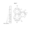
- FIG. 7 illustrates an example of a process for allocating a frequency resource for a multi-cell communication system.
- the multi-cell communication system includes a first cell, a second cell, and a third cell.
- the same inner frequency resource (F1) may be allocated to inner-cells 711, 721, and 731 of the first cell, the second cell, and third cell.
- a first frequency resource (F2 + F4) may be allocated to an outer-cell 712 of the first cell
- a second frequency resource (F2 + F3) may be allocated to an outer-cell 722 of the second cell
- a third frequency resource (F3 + F4) may be allocated to an outer cell 732 of the third cell. Accordingly, frequency resources F2 + F4, F2+ F3, and F3 + F4 may partially overlap each other.
- the rate splitting scheme may be applied in the cells by performing appropriate beamforming.
- a transmission and reception method performing beamforming using a rate splitting scheme in a multi-cell multi-antenna system according to an embodiment has been described herein.
- Various embodiments described with reference FIGS. 1 through 5 may be applied, however, for conciseness further description thereof is omitted.
- the processes, functions, methods and/or software described above may be recorded, stored, or fixed in one or more computer-readable storage media that includes program instructions to be implemented by a computer to cause a processor to execute or perform the program instructions.
- the media may also include, alone or in combination with the program instructions, data files, data structures, and the like.
- the media and program instructions may be those specially designed and constructed, or they may be of the kind well-known and available to those having skill in the computer software arts.
- Examples of computer-readable media include magnetic media, such as hard disks, floppy disks, and magnetic tape; optical media such as CD-ROM disks and DVDs; magneto-optical media, such as optical disks; and hardware devices that are specially configured to store and perform program instructions, such as read-only memory (ROM), random access memory (RAM), flash memory, and the like.
- Examples of program instructions include machine code, such as produced by a compiler, and files containing higher level code that may be executed by the computer using an interpreter.
- the described hardware devices may be configured to act as one or more software modules in order to perform the operations and methods described above, or vice versa.
- a computer-readable storage medium may be distributed among computer systems connected through a network and computer-readable codes or program instructions may be stored and executed in a decentralized manner.
Landscapes
- Engineering & Computer Science (AREA)
- Computer Networks & Wireless Communication (AREA)
- Signal Processing (AREA)
- Power Engineering (AREA)
- Mobile Radio Communication Systems (AREA)
- Radio Transmission System (AREA)
- Variable-Direction Aerials And Aerial Arrays (AREA)
Applications Claiming Priority (1)
| Application Number | Priority Date | Filing Date | Title |
|---|---|---|---|
| KR1020100025819A KR101636029B1 (ko) | 2010-03-23 | 2010-03-23 | 다중 셀 다중 안테나 시스템에서 레이트 스플리팅 기법을 사용하기 위한 빔포밍 방법 및 장치 |
Publications (3)
| Publication Number | Publication Date |
|---|---|
| EP2369757A2 true EP2369757A2 (fr) | 2011-09-28 |
| EP2369757A3 EP2369757A3 (fr) | 2011-11-16 |
| EP2369757B1 EP2369757B1 (fr) | 2018-06-06 |
Family
ID=44182643
Family Applications (1)
| Application Number | Title | Priority Date | Filing Date |
|---|---|---|---|
| EP11151254.7A Active EP2369757B1 (fr) | 2010-03-23 | 2011-01-18 | Procédé de formation de faisceau et appareil pour utiliser un schéma de division de débit dans un canal d'interférence à plusieurs cellules et plusieurs antennes |
Country Status (3)
| Country | Link |
|---|---|
| US (1) | US8976892B2 (fr) |
| EP (1) | EP2369757B1 (fr) |
| KR (1) | KR101636029B1 (fr) |
Cited By (6)
| Publication number | Priority date | Publication date | Assignee | Title |
|---|---|---|---|---|
| EP2749080A4 (fr) * | 2011-12-07 | 2015-04-15 | Ericsson Telefon Ab L M | Procédé et station de base centrale permettant une gestion d'interférence dans un réseau cellulaire |
| CN106160833A (zh) * | 2015-05-11 | 2016-11-23 | 国际商业机器公司 | 管理波束成形信号以优化传感器阵列的传输速率 |
| WO2017076335A1 (fr) * | 2015-11-06 | 2017-05-11 | Mediatek Inc. | Attribution de débit à division de débit pour une nouvelle interface radio adaptée à une annulation de brouillage |
| CN110611525A (zh) * | 2019-09-24 | 2019-12-24 | 北京邮电大学 | 一种基于速率分拆的信号传输、接收方法及装置 |
| CN108418613B (zh) * | 2018-01-02 | 2020-11-06 | 北京邮电大学 | 一种基于速率分拆的非对称上下行协作传输方法及装置 |
| WO2023239989A1 (fr) * | 2022-06-06 | 2023-12-14 | Qualcomm Incorporated | Cadre de signalisation pour division de débit |
Families Citing this family (12)
| Publication number | Priority date | Publication date | Assignee | Title |
|---|---|---|---|---|
| US20140036888A1 (en) * | 2011-04-27 | 2014-02-06 | Haralabos C. Papadopoulos | Method for efficient mu-mimo transmission via blind interference alignment schemes with reduced channel coherence-time requirements |
| KR20130016593A (ko) * | 2011-08-08 | 2013-02-18 | 삼성전자주식회사 | 네트워크 코딩을 수행하는 방법 및 네트워크 코딩을 수행하는 릴레이 |
| KR20130089459A (ko) | 2012-02-02 | 2013-08-12 | 삼성전자주식회사 | 무선통신 시스템에서 간섭 정렬 방법 및 장치 |
| KR20130102326A (ko) * | 2012-03-07 | 2013-09-17 | 삼성전자주식회사 | 분산 소형 기지국을 포함하는 이동 통신시스템에서의 데이터 송수신 장치 및 방법 |
| KR101935782B1 (ko) * | 2012-03-29 | 2019-01-08 | 삼성전자주식회사 | 다중 셀룰러 네트워크에서 신호의 송수신 방법 및 장치 |
| US10277295B2 (en) | 2014-01-29 | 2019-04-30 | The Boeing Company | Simultaneous nulling and beamfocusing from disparate antennas |
| KR101599668B1 (ko) * | 2015-03-19 | 2016-03-15 | 서울대학교산학협력단 | 빔 포밍 벡터 제공 시스템, 그 제공 장치, 그 제공 방법, 이를 수행하는 컴퓨터 프로그램 및 이를 기록한 기록매체 |
| WO2021112602A1 (fr) * | 2019-12-06 | 2021-06-10 | Lg Electronics Inc. | Procédé et appareil d'accès multiple |
| KR102805538B1 (ko) * | 2022-04-07 | 2025-05-12 | 한국전자통신연구원 | 빔포밍 신호 송수신 방법 및 이를 구현하기 위한 신호 송수신 장치 |
| CN115276744B (zh) * | 2022-06-23 | 2024-12-03 | 河北中创盈和通信科技有限公司 | 一种基于速率分割多址接入技术的毫米波系统传输方法 |
| US20240089151A1 (en) * | 2022-09-09 | 2024-03-14 | Qualcomm Incorporated | Phase tracking reference signal configuration for rate-splitting multiple input multiple output communications |
| US12464548B2 (en) * | 2023-03-06 | 2025-11-04 | Qualcomm Incorporated | Rate splitting multiple access for sidelink communication |
Family Cites Families (14)
| Publication number | Priority date | Publication date | Assignee | Title |
|---|---|---|---|---|
| KR100554922B1 (ko) | 2002-10-18 | 2006-03-10 | 엘지전자 주식회사 | 다중 빔 기반의 다중경로 탐색장치 및 방법 |
| US20050070256A1 (en) | 2003-09-29 | 2005-03-31 | Teck Hu | Method of dynamic rate splitting |
| US9246560B2 (en) | 2005-03-10 | 2016-01-26 | Qualcomm Incorporated | Systems and methods for beamforming and rate control in a multi-input multi-output communication systems |
| KR101257066B1 (ko) | 2005-09-06 | 2013-04-22 | 한국전자통신연구원 | 직교 주파수 분할 다중화 셀룰러 시스템에서 셀 간 간섭완화를 위한 하향 링크의 자원 분할, 할당 방법 및 송수신방법 |
| US20070077934A1 (en) | 2005-09-30 | 2007-04-05 | Aik Chindapol | Dynamic reuse partitioning and subchannel allocation scheme in multicell OFDMA downlink systems |
| US8374650B2 (en) * | 2006-09-27 | 2013-02-12 | Apple, Inc. | Methods for optimal collaborative MIMO-SDMA |
| KR100841933B1 (ko) | 2006-09-29 | 2008-06-27 | 포스데이타 주식회사 | 무선 통신 시스템에서 주파수 중복 사용 방법 및 장치 |
| US8483038B2 (en) | 2006-12-04 | 2013-07-09 | Ntt Docomo, Inc. | Radio communication apparatus and radio communication method |
| KR100758183B1 (ko) | 2007-05-03 | 2007-09-12 | 서교정보통신 주식회사 | 데이터 속도 분할 전송 장치 및 그 방법 |
| KR101421251B1 (ko) * | 2007-08-14 | 2014-07-18 | 한국과학기술원 | 중계기를 기반으로 하는 다중안테나 무선통신 시스템에서협력 중계를 위한 장치 및 방법 |
| US8656248B2 (en) * | 2007-12-13 | 2014-02-18 | Qualcomm Incorporated | Hierarchical CRC scheme |
| KR101402242B1 (ko) | 2008-04-16 | 2014-06-02 | 삼성전자주식회사 | 복합 분할 복신 기반의 다중 입출력 무선통신 시스템에서빔포밍 장치 및 방법 |
| US9755705B2 (en) | 2008-08-07 | 2017-09-05 | Qualcomm Incorporated | Method and apparatus for supporting multi-user and single-user MIMO in a wireless communication system |
| KR101169541B1 (ko) * | 2008-08-12 | 2012-07-30 | 엘지전자 주식회사 | 다중 셀 협력적 무선통신 시스템에서 하향링크 데이터를 전송하는 방법 |
-
2010
- 2010-03-23 KR KR1020100025819A patent/KR101636029B1/ko active Active
- 2010-10-22 US US12/909,997 patent/US8976892B2/en active Active
-
2011
- 2011-01-18 EP EP11151254.7A patent/EP2369757B1/fr active Active
Non-Patent Citations (1)
| Title |
|---|
| None |
Cited By (9)
| Publication number | Priority date | Publication date | Assignee | Title |
|---|---|---|---|---|
| EP2749080A4 (fr) * | 2011-12-07 | 2015-04-15 | Ericsson Telefon Ab L M | Procédé et station de base centrale permettant une gestion d'interférence dans un réseau cellulaire |
| US9917682B2 (en) | 2011-12-07 | 2018-03-13 | Telefonaktiebolaget Lm Ericsson (Publ) | Method and a central base station for interference management in a cellular network |
| CN106160833A (zh) * | 2015-05-11 | 2016-11-23 | 国际商业机器公司 | 管理波束成形信号以优化传感器阵列的传输速率 |
| WO2017076335A1 (fr) * | 2015-11-06 | 2017-05-11 | Mediatek Inc. | Attribution de débit à division de débit pour une nouvelle interface radio adaptée à une annulation de brouillage |
| US10104674B2 (en) | 2015-11-06 | 2018-10-16 | Hfi Innovation Inc. | Rate assignment with rate splitting for interference cancellation friendly new air interface |
| CN108418613B (zh) * | 2018-01-02 | 2020-11-06 | 北京邮电大学 | 一种基于速率分拆的非对称上下行协作传输方法及装置 |
| CN110611525A (zh) * | 2019-09-24 | 2019-12-24 | 北京邮电大学 | 一种基于速率分拆的信号传输、接收方法及装置 |
| WO2023239989A1 (fr) * | 2022-06-06 | 2023-12-14 | Qualcomm Incorporated | Cadre de signalisation pour division de débit |
| US12484058B2 (en) | 2022-06-06 | 2025-11-25 | Qualcomm Incorporated | Signaling framework for rate splitting |
Also Published As
| Publication number | Publication date |
|---|---|
| KR101636029B1 (ko) | 2016-07-20 |
| EP2369757A3 (fr) | 2011-11-16 |
| EP2369757B1 (fr) | 2018-06-06 |
| KR20110106646A (ko) | 2011-09-29 |
| US8976892B2 (en) | 2015-03-10 |
| US20110235750A1 (en) | 2011-09-29 |
Similar Documents
| Publication | Publication Date | Title |
|---|---|---|
| EP2369757B1 (fr) | Procédé de formation de faisceau et appareil pour utiliser un schéma de division de débit dans un canal d'interférence à plusieurs cellules et plusieurs antennes | |
| US12040878B2 (en) | Method for transmitting and receiving data in cooperative communication system, and cooperative communication method | |
| EP2618530B1 (fr) | Procédé et appareil d'estimation de canal à l'aide de codes de description multiples | |
| EP3481022B1 (fr) | Procédé de réception ou de transmission de données par ue ou station de base dans un schéma noma, ue utilisant celui-ci et station de base l'utilisant | |
| EP3094010B1 (fr) | Procédé et appareil de formation de faisceau coordonnée basée sur un alignement de brouillage partiel | |
| US9124313B2 (en) | Multi-cell cooperative communication system and terminal device | |
| EP2242189A1 (fr) | Appareil et procédé de contrôle de l'alimentation dans un système de communication sans fil à entrées/sorties multiple distribuées | |
| KR102508858B1 (ko) | 송신 다이버시티를 위한 방법 및 장치 | |
| EP2911330B1 (fr) | Procédé, système et dispositif pour transmettre des informations d'instruction de codage et pour déterminer une matrice de précodage | |
| RU2658901C1 (ru) | Способ, аппарат и устройство для обработки данных | |
| EP2814192B1 (fr) | Procédé, dispositif et système d'émission de signaux | |
| US10271222B2 (en) | Omni-directional transmission in large-scale MIMO systems | |
| KR101512585B1 (ko) | 협력 다중 포인트 송신/수신의 업링크 채널 자원을 할당하기 위한 방법 및 디바이스 | |
| EP2890034A1 (fr) | Dispositif et procédé de traitement d'informations de commande de liaison descendante | |
| CN114830607B (zh) | 用于大型多维无线系统的无线x2x接入方法和接收器 | |
| EP2913949B1 (fr) | Procédé, système et dispositif de transmission d'informations d'indication précodées et de détermination d'une matrice de précodage | |
| US8520759B2 (en) | Apparatus and method for detecting signal based on lattice reduction to support different coding scheme for each stream in multiple input multiple output wireless communication system | |
| EP2485423A1 (fr) | Procédé de précodage dans un système de relais coopératif, dispositif de communication et dispositif relais | |
| Wang et al. | Relay-aided interference alignment for MIMO cellular networks | |
| CN101488837B (zh) | 一种多播广播业务数据发射方法及无线发射装置 | |
| US20100166038A1 (en) | Device and method of feeding back channel information | |
| CN105812041A (zh) | 两小区的mimo广播信道中一种消除多用户干扰的方法 | |
| KR101267569B1 (ko) | 다중 안테나 시스템의 송신 장치 및 그 송신 방법 | |
| KR100984737B1 (ko) | 다중 사용자 mimo 중계 시스템에서 기지국의 간섭신호제거 방법 | |
| KR101105049B1 (ko) | 셀 기반 무선 통신 시스템에서 인접 셀에 의한 간섭을 제거하기 위한 송신 및 수신 방법 |
Legal Events
| Date | Code | Title | Description |
|---|---|---|---|
| PUAI | Public reference made under article 153(3) epc to a published international application that has entered the european phase |
Free format text: ORIGINAL CODE: 0009012 |
|
| AK | Designated contracting states |
Kind code of ref document: A2 Designated state(s): AL AT BE BG CH CY CZ DE DK EE ES FI FR GB GR HR HU IE IS IT LI LT LU LV MC MK MT NL NO PL PT RO RS SE SI SK SM TR |
|
| AX | Request for extension of the european patent |
Extension state: BA ME |
|
| PUAL | Search report despatched |
Free format text: ORIGINAL CODE: 0009013 |
|
| AK | Designated contracting states |
Kind code of ref document: A3 Designated state(s): AL AT BE BG CH CY CZ DE DK EE ES FI FR GB GR HR HU IE IS IT LI LT LU LV MC MK MT NL NO PL PT RO RS SE SI SK SM TR |
|
| AX | Request for extension of the european patent |
Extension state: BA ME |
|
| RIC1 | Information provided on ipc code assigned before grant |
Ipc: H04W 16/30 20090101ALI20111011BHEP Ipc: H04L 1/00 20060101ALI20111011BHEP Ipc: H04B 7/04 20060101ALI20111011BHEP Ipc: H04B 7/06 20060101AFI20111011BHEP |
|
| 17P | Request for examination filed |
Effective date: 20120516 |
|
| RAP1 | Party data changed (applicant data changed or rights of an application transferred) |
Owner name: SAMSUNG ELECTRONICS CO., LTD. |
|
| GRAP | Despatch of communication of intention to grant a patent |
Free format text: ORIGINAL CODE: EPIDOSNIGR1 |
|
| STAA | Information on the status of an ep patent application or granted ep patent |
Free format text: STATUS: GRANT OF PATENT IS INTENDED |
|
| RIC1 | Information provided on ipc code assigned before grant |
Ipc: H04B 7/0452 20170101ALI20171130BHEP Ipc: H04W 16/30 20090101ALI20171130BHEP Ipc: H04B 7/06 20060101AFI20171130BHEP Ipc: H04L 1/00 20060101ALI20171130BHEP Ipc: H04B 7/04 20170101ALI20171130BHEP |
|
| INTG | Intention to grant announced |
Effective date: 20180103 |
|
| GRAS | Grant fee paid |
Free format text: ORIGINAL CODE: EPIDOSNIGR3 |
|
| GRAA | (expected) grant |
Free format text: ORIGINAL CODE: 0009210 |
|
| STAA | Information on the status of an ep patent application or granted ep patent |
Free format text: STATUS: THE PATENT HAS BEEN GRANTED |
|
| AK | Designated contracting states |
Kind code of ref document: B1 Designated state(s): AL AT BE BG CH CY CZ DE DK EE ES FI FR GB GR HR HU IE IS IT LI LT LU LV MC MK MT NL NO PL PT RO RS SE SI SK SM TR |
|
| REG | Reference to a national code |
Ref country code: GB Ref legal event code: FG4D |
|
| REG | Reference to a national code |
Ref country code: CH Ref legal event code: EP Ref country code: AT Ref legal event code: REF Ref document number: 1007178 Country of ref document: AT Kind code of ref document: T Effective date: 20180615 |
|
| REG | Reference to a national code |
Ref country code: IE Ref legal event code: FG4D |
|
| REG | Reference to a national code |
Ref country code: DE Ref legal event code: R096 Ref document number: 602011048969 Country of ref document: DE |
|
| REG | Reference to a national code |
Ref country code: NL Ref legal event code: MP Effective date: 20180606 |
|
| REG | Reference to a national code |
Ref country code: LT Ref legal event code: MG4D |
|
| PG25 | Lapsed in a contracting state [announced via postgrant information from national office to epo] |
Ref country code: NO Free format text: LAPSE BECAUSE OF FAILURE TO SUBMIT A TRANSLATION OF THE DESCRIPTION OR TO PAY THE FEE WITHIN THE PRESCRIBED TIME-LIMIT Effective date: 20180906 Ref country code: FI Free format text: LAPSE BECAUSE OF FAILURE TO SUBMIT A TRANSLATION OF THE DESCRIPTION OR TO PAY THE FEE WITHIN THE PRESCRIBED TIME-LIMIT Effective date: 20180606 Ref country code: BG Free format text: LAPSE BECAUSE OF FAILURE TO SUBMIT A TRANSLATION OF THE DESCRIPTION OR TO PAY THE FEE WITHIN THE PRESCRIBED TIME-LIMIT Effective date: 20180906 Ref country code: LT Free format text: LAPSE BECAUSE OF FAILURE TO SUBMIT A TRANSLATION OF THE DESCRIPTION OR TO PAY THE FEE WITHIN THE PRESCRIBED TIME-LIMIT Effective date: 20180606 Ref country code: CY Free format text: LAPSE BECAUSE OF FAILURE TO SUBMIT A TRANSLATION OF THE DESCRIPTION OR TO PAY THE FEE WITHIN THE PRESCRIBED TIME-LIMIT Effective date: 20180606 Ref country code: ES Free format text: LAPSE BECAUSE OF FAILURE TO SUBMIT A TRANSLATION OF THE DESCRIPTION OR TO PAY THE FEE WITHIN THE PRESCRIBED TIME-LIMIT Effective date: 20180606 Ref country code: SE Free format text: LAPSE BECAUSE OF FAILURE TO SUBMIT A TRANSLATION OF THE DESCRIPTION OR TO PAY THE FEE WITHIN THE PRESCRIBED TIME-LIMIT Effective date: 20180606 |
|
| PG25 | Lapsed in a contracting state [announced via postgrant information from national office to epo] |
Ref country code: LV Free format text: LAPSE BECAUSE OF FAILURE TO SUBMIT A TRANSLATION OF THE DESCRIPTION OR TO PAY THE FEE WITHIN THE PRESCRIBED TIME-LIMIT Effective date: 20180606 Ref country code: HR Free format text: LAPSE BECAUSE OF FAILURE TO SUBMIT A TRANSLATION OF THE DESCRIPTION OR TO PAY THE FEE WITHIN THE PRESCRIBED TIME-LIMIT Effective date: 20180606 Ref country code: GR Free format text: LAPSE BECAUSE OF FAILURE TO SUBMIT A TRANSLATION OF THE DESCRIPTION OR TO PAY THE FEE WITHIN THE PRESCRIBED TIME-LIMIT Effective date: 20180907 Ref country code: RS Free format text: LAPSE BECAUSE OF FAILURE TO SUBMIT A TRANSLATION OF THE DESCRIPTION OR TO PAY THE FEE WITHIN THE PRESCRIBED TIME-LIMIT Effective date: 20180606 |
|
| REG | Reference to a national code |
Ref country code: AT Ref legal event code: MK05 Ref document number: 1007178 Country of ref document: AT Kind code of ref document: T Effective date: 20180606 |
|
| PG25 | Lapsed in a contracting state [announced via postgrant information from national office to epo] |
Ref country code: NL Free format text: LAPSE BECAUSE OF FAILURE TO SUBMIT A TRANSLATION OF THE DESCRIPTION OR TO PAY THE FEE WITHIN THE PRESCRIBED TIME-LIMIT Effective date: 20180606 |
|
| PG25 | Lapsed in a contracting state [announced via postgrant information from national office to epo] |
Ref country code: IS Free format text: LAPSE BECAUSE OF FAILURE TO SUBMIT A TRANSLATION OF THE DESCRIPTION OR TO PAY THE FEE WITHIN THE PRESCRIBED TIME-LIMIT Effective date: 20181006 Ref country code: EE Free format text: LAPSE BECAUSE OF FAILURE TO SUBMIT A TRANSLATION OF THE DESCRIPTION OR TO PAY THE FEE WITHIN THE PRESCRIBED TIME-LIMIT Effective date: 20180606 Ref country code: PL Free format text: LAPSE BECAUSE OF FAILURE TO SUBMIT A TRANSLATION OF THE DESCRIPTION OR TO PAY THE FEE WITHIN THE PRESCRIBED TIME-LIMIT Effective date: 20180606 Ref country code: AT Free format text: LAPSE BECAUSE OF FAILURE TO SUBMIT A TRANSLATION OF THE DESCRIPTION OR TO PAY THE FEE WITHIN THE PRESCRIBED TIME-LIMIT Effective date: 20180606 Ref country code: CZ Free format text: LAPSE BECAUSE OF FAILURE TO SUBMIT A TRANSLATION OF THE DESCRIPTION OR TO PAY THE FEE WITHIN THE PRESCRIBED TIME-LIMIT Effective date: 20180606 Ref country code: RO Free format text: LAPSE BECAUSE OF FAILURE TO SUBMIT A TRANSLATION OF THE DESCRIPTION OR TO PAY THE FEE WITHIN THE PRESCRIBED TIME-LIMIT Effective date: 20180606 Ref country code: SK Free format text: LAPSE BECAUSE OF FAILURE TO SUBMIT A TRANSLATION OF THE DESCRIPTION OR TO PAY THE FEE WITHIN THE PRESCRIBED TIME-LIMIT Effective date: 20180606 |
|
| REG | Reference to a national code |
Ref country code: CH Ref legal event code: PK Free format text: BERICHTIGUNGEN |
|
| RIC2 | Information provided on ipc code assigned after grant |
Ipc: H04W 16/30 20090101ALI20171130BHEP Ipc: H04B 7/0452 20170101ALI20171130BHEP Ipc: H04B 7/04 20170101ALI20171130BHEP Ipc: H04B 7/06 20060101AFI20171130BHEP Ipc: H04L 1/00 20060101ALI20171130BHEP |
|
| PG25 | Lapsed in a contracting state [announced via postgrant information from national office to epo] |
Ref country code: SM Free format text: LAPSE BECAUSE OF FAILURE TO SUBMIT A TRANSLATION OF THE DESCRIPTION OR TO PAY THE FEE WITHIN THE PRESCRIBED TIME-LIMIT Effective date: 20180606 Ref country code: IT Free format text: LAPSE BECAUSE OF FAILURE TO SUBMIT A TRANSLATION OF THE DESCRIPTION OR TO PAY THE FEE WITHIN THE PRESCRIBED TIME-LIMIT Effective date: 20180606 |
|
| REG | Reference to a national code |
Ref country code: DE Ref legal event code: R097 Ref document number: 602011048969 Country of ref document: DE |
|
| PLBE | No opposition filed within time limit |
Free format text: ORIGINAL CODE: 0009261 |
|
| STAA | Information on the status of an ep patent application or granted ep patent |
Free format text: STATUS: NO OPPOSITION FILED WITHIN TIME LIMIT |
|
| 26N | No opposition filed |
Effective date: 20190307 |
|
| PG25 | Lapsed in a contracting state [announced via postgrant information from national office to epo] |
Ref country code: SI Free format text: LAPSE BECAUSE OF FAILURE TO SUBMIT A TRANSLATION OF THE DESCRIPTION OR TO PAY THE FEE WITHIN THE PRESCRIBED TIME-LIMIT Effective date: 20180606 Ref country code: DK Free format text: LAPSE BECAUSE OF FAILURE TO SUBMIT A TRANSLATION OF THE DESCRIPTION OR TO PAY THE FEE WITHIN THE PRESCRIBED TIME-LIMIT Effective date: 20180606 |
|
| PG25 | Lapsed in a contracting state [announced via postgrant information from national office to epo] |
Ref country code: MC Free format text: LAPSE BECAUSE OF FAILURE TO SUBMIT A TRANSLATION OF THE DESCRIPTION OR TO PAY THE FEE WITHIN THE PRESCRIBED TIME-LIMIT Effective date: 20180606 |
|
| REG | Reference to a national code |
Ref country code: CH Ref legal event code: PL |
|
| PG25 | Lapsed in a contracting state [announced via postgrant information from national office to epo] |
Ref country code: LU Free format text: LAPSE BECAUSE OF NON-PAYMENT OF DUE FEES Effective date: 20190118 |
|
| REG | Reference to a national code |
Ref country code: BE Ref legal event code: MM Effective date: 20190131 |
|
| REG | Reference to a national code |
Ref country code: IE Ref legal event code: MM4A |
|
| PG25 | Lapsed in a contracting state [announced via postgrant information from national office to epo] |
Ref country code: BE Free format text: LAPSE BECAUSE OF NON-PAYMENT OF DUE FEES Effective date: 20190131 Ref country code: AL Free format text: LAPSE BECAUSE OF FAILURE TO SUBMIT A TRANSLATION OF THE DESCRIPTION OR TO PAY THE FEE WITHIN THE PRESCRIBED TIME-LIMIT Effective date: 20180606 |
|
| PG25 | Lapsed in a contracting state [announced via postgrant information from national office to epo] |
Ref country code: LI Free format text: LAPSE BECAUSE OF NON-PAYMENT OF DUE FEES Effective date: 20190131 Ref country code: CH Free format text: LAPSE BECAUSE OF NON-PAYMENT OF DUE FEES Effective date: 20190131 |
|
| PG25 | Lapsed in a contracting state [announced via postgrant information from national office to epo] |
Ref country code: IE Free format text: LAPSE BECAUSE OF NON-PAYMENT OF DUE FEES Effective date: 20190118 |
|
| PG25 | Lapsed in a contracting state [announced via postgrant information from national office to epo] |
Ref country code: TR Free format text: LAPSE BECAUSE OF FAILURE TO SUBMIT A TRANSLATION OF THE DESCRIPTION OR TO PAY THE FEE WITHIN THE PRESCRIBED TIME-LIMIT Effective date: 20180606 |
|
| PG25 | Lapsed in a contracting state [announced via postgrant information from national office to epo] |
Ref country code: MT Free format text: LAPSE BECAUSE OF NON-PAYMENT OF DUE FEES Effective date: 20190118 Ref country code: PT Free format text: LAPSE BECAUSE OF FAILURE TO SUBMIT A TRANSLATION OF THE DESCRIPTION OR TO PAY THE FEE WITHIN THE PRESCRIBED TIME-LIMIT Effective date: 20181008 |
|
| PG25 | Lapsed in a contracting state [announced via postgrant information from national office to epo] |
Ref country code: HU Free format text: LAPSE BECAUSE OF FAILURE TO SUBMIT A TRANSLATION OF THE DESCRIPTION OR TO PAY THE FEE WITHIN THE PRESCRIBED TIME-LIMIT; INVALID AB INITIO Effective date: 20110118 |
|
| PG25 | Lapsed in a contracting state [announced via postgrant information from national office to epo] |
Ref country code: MK Free format text: LAPSE BECAUSE OF FAILURE TO SUBMIT A TRANSLATION OF THE DESCRIPTION OR TO PAY THE FEE WITHIN THE PRESCRIBED TIME-LIMIT Effective date: 20180606 |
|
| P01 | Opt-out of the competence of the unified patent court (upc) registered |
Effective date: 20230530 |
|
| PGFP | Annual fee paid to national office [announced via postgrant information from national office to epo] |
Ref country code: GB Payment date: 20251211 Year of fee payment: 16 |
|
| PGFP | Annual fee paid to national office [announced via postgrant information from national office to epo] |
Ref country code: FR Payment date: 20251222 Year of fee payment: 16 |
|
| PGFP | Annual fee paid to national office [announced via postgrant information from national office to epo] |
Ref country code: DE Payment date: 20251216 Year of fee payment: 16 |