EP2369772A2 - Übertragungsdiversität unter Verwendung räumlichen Multiplexings mit geringer Coderate - Google Patents
Übertragungsdiversität unter Verwendung räumlichen Multiplexings mit geringer Coderate Download PDFInfo
- Publication number
- EP2369772A2 EP2369772A2 EP20110150427 EP11150427A EP2369772A2 EP 2369772 A2 EP2369772 A2 EP 2369772A2 EP 20110150427 EP20110150427 EP 20110150427 EP 11150427 A EP11150427 A EP 11150427A EP 2369772 A2 EP2369772 A2 EP 2369772A2
- Authority
- EP
- European Patent Office
- Prior art keywords
- bits
- antenna
- channel coded
- channel
- coded bits
- Prior art date
- Legal status (The legal status is an assumption and is not a legal conclusion. Google has not performed a legal analysis and makes no representation as to the accuracy of the status listed.)
- Granted
Links
Images





Classifications
-
- H—ELECTRICITY
- H04—ELECTRIC COMMUNICATION TECHNIQUE
- H04B—TRANSMISSION
- H04B7/00—Radio transmission systems, i.e. using radiation field
- H04B7/02—Diversity systems; Multi-antenna system, i.e. transmission or reception using multiple antennas
- H04B7/04—Diversity systems; Multi-antenna system, i.e. transmission or reception using multiple antennas using two or more spaced independent antennas
- H04B7/06—Diversity systems; Multi-antenna system, i.e. transmission or reception using multiple antennas using two or more spaced independent antennas at the transmitting station
- H04B7/0697—Diversity systems; Multi-antenna system, i.e. transmission or reception using multiple antennas using two or more spaced independent antennas at the transmitting station using spatial multiplexing
-
- H—ELECTRICITY
- H04—ELECTRIC COMMUNICATION TECHNIQUE
- H04B—TRANSMISSION
- H04B7/00—Radio transmission systems, i.e. using radiation field
- H04B7/02—Diversity systems; Multi-antenna system, i.e. transmission or reception using multiple antennas
- H04B7/04—Diversity systems; Multi-antenna system, i.e. transmission or reception using multiple antennas using two or more spaced independent antennas
- H04B7/06—Diversity systems; Multi-antenna system, i.e. transmission or reception using multiple antennas using two or more spaced independent antennas at the transmitting station
- H04B7/0613—Diversity systems; Multi-antenna system, i.e. transmission or reception using multiple antennas using two or more spaced independent antennas at the transmitting station using simultaneous transmission
- H04B7/0678—Diversity systems; Multi-antenna system, i.e. transmission or reception using multiple antennas using two or more spaced independent antennas at the transmitting station using simultaneous transmission using different spreading codes between antennas
-
- H—ELECTRICITY
- H04—ELECTRIC COMMUNICATION TECHNIQUE
- H04J—MULTIPLEX COMMUNICATION
- H04J11/00—Orthogonal multiplex systems, e.g. using WALSH codes
- H04J11/0023—Interference mitigation or co-ordination
- H04J11/0026—Interference mitigation or co-ordination of multi-user interference
- H04J11/003—Interference mitigation or co-ordination of multi-user interference at the transmitter
- H04J11/0033—Interference mitigation or co-ordination of multi-user interference at the transmitter by pre-cancellation of known interference, e.g. using a matched filter, dirty paper coder or Thomlinson-Harashima precoder
-
- H—ELECTRICITY
- H04—ELECTRIC COMMUNICATION TECHNIQUE
- H04J—MULTIPLEX COMMUNICATION
- H04J13/00—Code division multiplex systems
- H04J13/0003—Code application, i.e. aspects relating to how codes are applied to form multiplexed channels
-
- H—ELECTRICITY
- H04—ELECTRIC COMMUNICATION TECHNIQUE
- H04J—MULTIPLEX COMMUNICATION
- H04J13/00—Code division multiplex systems
- H04J13/0074—Code shifting or hopping
-
- H—ELECTRICITY
- H04—ELECTRIC COMMUNICATION TECHNIQUE
- H04L—TRANSMISSION OF DIGITAL INFORMATION, e.g. TELEGRAPHIC COMMUNICATION
- H04L1/00—Arrangements for detecting or preventing errors in the information received
- H04L1/004—Arrangements for detecting or preventing errors in the information received by using forward error control
- H04L1/0072—Error control for data other than payload data, e.g. control data
- H04L1/0073—Special arrangements for feedback channel
-
- H—ELECTRICITY
- H04—ELECTRIC COMMUNICATION TECHNIQUE
- H04L—TRANSMISSION OF DIGITAL INFORMATION, e.g. TELEGRAPHIC COMMUNICATION
- H04L1/00—Arrangements for detecting or preventing errors in the information received
- H04L1/02—Arrangements for detecting or preventing errors in the information received by diversity reception
- H04L1/06—Arrangements for detecting or preventing errors in the information received by diversity reception using space diversity
-
- H—ELECTRICITY
- H04—ELECTRIC COMMUNICATION TECHNIQUE
- H04L—TRANSMISSION OF DIGITAL INFORMATION, e.g. TELEGRAPHIC COMMUNICATION
- H04L5/00—Arrangements affording multiple use of the transmission path
- H04L5/0001—Arrangements for dividing the transmission path
- H04L5/0014—Three-dimensional division
- H04L5/0023—Time-frequency-space
-
- H—ELECTRICITY
- H04—ELECTRIC COMMUNICATION TECHNIQUE
- H04L—TRANSMISSION OF DIGITAL INFORMATION, e.g. TELEGRAPHIC COMMUNICATION
- H04L5/00—Arrangements affording multiple use of the transmission path
- H04L5/0001—Arrangements for dividing the transmission path
- H04L5/0026—Division using four or more dimensions, e.g. beam steering or quasi-co-location [QCL]
-
- H—ELECTRICITY
- H04—ELECTRIC COMMUNICATION TECHNIQUE
- H04L—TRANSMISSION OF DIGITAL INFORMATION, e.g. TELEGRAPHIC COMMUNICATION
- H04L5/00—Arrangements affording multiple use of the transmission path
- H04L5/003—Arrangements for allocating sub-channels of the transmission path
- H04L5/0053—Allocation of signalling, i.e. of overhead other than pilot signals
- H04L5/0057—Physical resource allocation for CQI
-
- H—ELECTRICITY
- H04—ELECTRIC COMMUNICATION TECHNIQUE
- H04L—TRANSMISSION OF DIGITAL INFORMATION, e.g. TELEGRAPHIC COMMUNICATION
- H04L5/00—Arrangements affording multiple use of the transmission path
- H04L5/003—Arrangements for allocating sub-channels of the transmission path
- H04L5/0053—Allocation of signalling, i.e. of overhead other than pilot signals
-
- H—ELECTRICITY
- H04—ELECTRIC COMMUNICATION TECHNIQUE
- H04L—TRANSMISSION OF DIGITAL INFORMATION, e.g. TELEGRAPHIC COMMUNICATION
- H04L5/00—Arrangements affording multiple use of the transmission path
- H04L5/0091—Signalling for the administration of the divided path, e.g. signalling of configuration information
Definitions
- the terms “user equipment” and “UE” can refer to wireless devices such as mobile telephones, personal digital assistants, handheld or laptop computers, and similar devices that have telecommunications capabilities. Such a UE might consist of a wireless device and its associated Universal Integrated Circuit Card (UICC) that includes a Subscriber Identity Module (SIM) application, a Universal Subscriber Identity Module (USIM) application, or a Removable User Identity Module (R-UIM) application or might consist of the device itself without such a card.
- SIM Subscriber Identity Module
- USIM Universal Subscriber Identity Module
- R-UIM Removable User Identity Module
- the term “UE” may also refer to devices that have similar wireless capabilities but that are not transportable, such as desktop computers, set-top boxes, or network appliances.
- the term “UE” can also refer to any hardware or software component that can terminate a communication session for a user.
- the terms “user equipment,” “UE,” “user agent,” “UA,” “user device” and “user node” might be used synonymously herein.
- LTE Long Term Evolution
- LTE-A LTE-Advanced
- eNB evolved Node B
- a wireless access point or a similar component rather than a traditional base station.
- eNB or "access node” will refer to any component of a wireless network, such as a traditional base station, a wireless access point, or an LTE or LTE-A eNB, that creates a geographical area of reception and transmission coverage allowing a UE or a relay node to access other components in a telecommunications system.
- An access node may comprise a plurality of hardware and software.
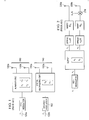
- Figure 1 is a diagram of multi-antenna transmission approaches, according to the prior art.
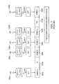
- FIG. 2 is a diagram of antenna virtualization, according to the prior art.
- FIG. 3 is a diagram of the PUCCH (Physical Uplink Control Channel) format 2 structure and spreading, according to the prior art.
- PUCCH Physical Uplink Control Channel
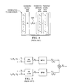
- Figure 4 is a diagram of a receiver structure, according to the prior art.
- Figure 5 is a diagram of an encoder split into two five-bit paths, according to the prior art.
- Figure 6 is a diagram of SORTD (Space-Orthogonal Transmit Diversity), according to the prior art.
- Figure 7 is a diagram of simple repetition for SORTD, according to the prior art.
- Figure 8 is a diagram of joint coding for SORTD, according to the prior art.
- Figure 9 is a diagram of STBC (Space Time Block Code) for PUCCH format 2, according to the prior art.
- Figure 10 is a diagram of low code rate spatial multiplexing, according to an embodiment of the disclosure.
- Figure 11 is a diagram of variable orthogonality low code rate spatial multiplexing, according to an embodiment of the disclosure.
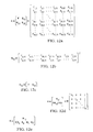
- Figures 12a - 12e depict equations that may be used in low code rate spatial multiplexing, according to an embodiment of the disclosure.
- Figure 13 depicts tables that may be used in low code rate spatial multiplexing, according to an embodiment of the disclosure.
- Figure 14 is a diagram of a receiver structure for a repeat-and-spread extended Reed-Muller code, according to an embodiment of the disclosure.
- Figure 15 is a diagram of a receiver structure for a low-rank extended Reed-Muller code, according to an embodiment of the disclosure.
- Figure 16 is a diagram of virtualized variable orthogonality low code rate spatial multiplexing, according to an embodiment of the disclosure.
- Figure 17 illustrates an embodiment of a method for communication in a wireless telecommunications system, according to an alternative embodiment of the disclosure.
- Figure 18 illustrates a processor and related components suitable for implementing the several embodiments of the present disclosure.
- Multi-antenna UE transmission is a key component of the current LTE-A work in the Third Generation Partnership Project (3GPP).
- the present disclosure provides a flexible transmit diversity technique suitable for use on the LTE-A physical uplink control channel (PUCCH) that avoids drawbacks of existing techniques proposed for the PUCCH, that can use channel coding that is backward compatible with existing LTE PUCCH codes, and that provides performance comparable to techniques that use twice as many orthogonal resources (and therefore allow half as many users to share the same total PUCCH resources).
- PUCCH physical uplink control channel
- transmit diversity Two general approaches have been developed for multi-antenna transmission: transmit diversity and spatial multiplexing. These two techniques are normally thought of as mutually exclusive, with transmit diversity being used to improve robustness in poorer channel conditions and spatial multiplexing being used to improve throughput in better channel conditions.
- the top portion 110 of Figure 1 shows a commonly used space time block code (STBC), the "Alamouti" code, that can be used for transmit diversity.
- STBC space time block code
- a forward error correction (FEC) code is typically used, and then the coded symbols are modulated to form a symbol stream, 's' 120. These symbols are taken two at a time, and then the first symbol is transmitted on a first antenna 130a at a first time, while at the same time the second symbol is transmitted on a second antenna 130b. At a second time instant, the second symbol is negated and conjugated and transmitted on the first antenna 130a, while at the same time the first symbol is conjugated and transmitted on the second antenna 130b.
- STBC space time block code
- FEC forward error correction
- the number of symbols transmitted on the antennas 130 is the same as the number of symbols produced by the modulation and coding (that is, this is a "rate one STBC"). Due to the properties of the STBC, a receiver can recover the two transmitted symbols such that the power from the two antennas 130 combines efficiently, and excellent diversity gain is achieved. This diversity gain reduces the chance of an erroneous reception, improving performance under difficult channel conditions. However, unlike spatial multiplexing, it does not increase the number of symbols that can be transmitted on a channel.
- the bottom part 140 of Figure 1 shows a simple spatial multiplexing approach.
- a cyclic redundancy check (CRC) code is used along with FEC and modulation.
- the modulated symbols are then simply split between the two antennas 150 and transmitted simultaneously on both antennas 150. If there is sufficient scattering in the radio propagation and a sufficiently high signal-to-noise ratio (SNR), a receiving device (not shown) with two antennas will have independent measurements of the combined symbols, and can separate them and successfully decode the transmission.
- the number of symbols per antenna 150 is half the number of symbols out of the CRC+FEC+Mod block 160. This allows the information data rate in the same bandwidth to be doubled.
- the additional transmit diversity gain from using more than two antennas over that of two antennas diminishes with increasing diversity from other sources such as more receive antennas, frequency diversity from multipath, time diversity from HARQ or interleaving, etc.
- a UE has more than two transmit antennas, it still can be important to transmit on all the antennas in order to make the most efficient use of the UE's power amplifiers. Therefore, schemes that extend two antenna transmit diversity to more antennas are of interest.
- Antenna virtualization can be defined as transmitting on multiple antennas in such a way that they appear as a single antenna from the receiver's perspective.
- a virtualized antenna may be defined as one of a set of antennas that transmit together and appear as a single antenna.
- a virtual antenna may be defined as the set of antennas that appear as a single antenna. If coherent demodulation is used, this typically requires that a single reference signal (labeled in the figure as RS 1 ) be used as a phase reference for physical channels transmitted through the virtualized antennas.
- Figure 2 also uses a complex weight sequence w 1 ( k ) 210 on the second 220b of the virtualized antennas 220.
- the weight sequence 210 can be applied in time and/or frequency, such that it varies by subcarrier and/or by orthogonal frequency division multiplexing (OFDM) symbol.
- OFDM orthogonal frequency division multiplexing
- a time-frequency element may be defined as the smallest data or signal bearing unit of a physical layer. For example, for LTE, a resource element is a time-frequency element.
- a chip time is a time-frequency element.
- This is done in Figure 2 by multiplying the signals on the second antenna 220b with the complex weight sequence w 1 ( k ) 210.
- This complex weight sequence 210 allows the effective antenna pattern of the virtualized antennas to vary over the transmission of a single coded block of information bits, and to therefore provide diversity. If w 1 ( k ) 210 is fixed such that the same weight value is applied to all the frequency domain components of an OFDM symbol, but different weight values are used in the time domain for different OFDM symbols or slots containing one coded block, this corresponds to precoding vector switching (PVS).
- PVS precoding vector switching
- w i ( k ) e j ⁇ i(k) for the i th virtual antenna. Since only a few distinct antenna patterns are likely to be needed, w i ( k ) can be set to be an element of ⁇ +1-1,+ j - j ⁇ for all the virtualized antennas, allowing a simple implementation of the phase shift.
- the reference signals are transmitted in a time division multiplexing (TDM) fashion occupying all of an OFDM symbol as is done for the LTE uplink, it is desirable to keep w i ( k ) constant over an entire slot so that the reference symbol is transmitted with the same effective antenna pattern as all the other OFDM symbols in the slot.
- TDM time division multiplexing
- the LTE PUCCH has two major sets of formats: 1, 1 a, and 1b, and 2, 2a, and 2b.
- the format 1 set carries at most two bits and is used for HARQ acknowledgement/negative acknowledgement (ACK/NACK) and scheduling request signaling.
- the format 2 set carries at most 13 information bits containing channel quality information (CQI), rank indication (RI), and precoding matrix indications (PMI).
- CQI channel quality information
- RI rank indication
- PMI precoding matrix indications
- slot 2 of PUCCH formats 2, 2a, and 2b is shown in Figure 3 .
- the first slot has the same structure for formats 2, 2a, and 2b, but carries symbols d(0) through d(4).
- the only difference between format 2 and formats 2a and 2b is that the second RS 310b of formats 2a and 2b is modified to carry an ACK/NACK symbol in both slots. Therefore, the present disclosure concentrates on format 2.
- each PUCCH slot is composed of five OFDM symbols 320 that carry data and two OFDM symbols 310 that only carry reference signals.
- Each data-bearing OFDM symbol 320 is associated with one quadrature phase-shift keying (QPSK) modulation symbol, d(n) 330, that represents two coded bits.
- QPSK quadrature phase-shift keying
- PUCCH decoding is not as challenging as many decoding problems today whose block lengths are thousands of bits.
- PUCCH CQI transmissions have only up to 13 information bits, and so even a brute force search of all possible code words is not computationally prohibitive.
- FHT fast Hadamard transform
- ML maximum likelihood
- the channel code used in LTE on PUCCH formats 2, 2a, and 2b is in the family of Reed-Muller (RM) codes, and well known high performance ML receivers can be constructed using an FHT. Variants of these codes are likely to be used in LTE-A, and the present disclosure provides some variants. As discussed below, the use of FHTs can dramatically reduce the decoding complexity. The following discussion briefly explains how FHTs can be used to decode a Reed-Muller code, but does not describe the derivation of the method.
- RM Reed-Muller
- FIG. 4 A receiver structure that uses FHT-based decoding is shown in Figure 4 .
- bold capital symbols are matrices
- bold lower case symbols are vectors
- element-wise multiplication are assumed for concreteness. That is, 10 information bits are input to the encoder, which then produces an output of 32 channel bits (or channel coded bits). This results in a code rate of 10/32 or approximately 1/3.
- Each element of the received signal vector, r 410 is first multiplied by a corresponding element of a (channel dependent) combining weight vector, h 420.
- a simple OFDM receiver might use a matched filter receiver, where the elements of h 420 are the complex conjugate of the channel estimate corresponding to the subcarrier and time slot that the received signal passes through.
- the c 2 ( b 2 ) 430 term is assumed to be all ones and is neglected.
- n th order Hadamard matrix is a subset of the n th order Reed-Muller code, and so the decoder's combining can be done (at least in part) with G 440 being a Hadamard matrix, or equivalently by taking an FHT. Taking an FHT is computationally preferable and a candidate to be used in any implementation.
- the LTE PUCCH formats 2, 2a, and 2b code is in the family of 5 th order Reed-Muller codes, and so a 5 th order FHT is used to decode.
- a binary phase-shift keying (BPSK) modulated encoder output can be expressed as the product of two modulated, encoded, information bit sequences, where each of the sequences is composed of five zeros and five of the information bits. Therefore, if one of the five information bit sequences is known, a modulated, encoded 10 information bit sequence can be multiplied (or "masked") by the modulated, encoded sequence corresponding to the known five information bit sequence to produce a sequence that is uniquely determined by only the five unknown information bits.
- BPSK binary phase-shift keying
- the kernel of the decoding process consists of hypothesizing a sequence of five information bits, masking the combining weighted received signal with a modulated, encoded sequence, taking an FHT of the masked sequence, and storing the value with the greatest correlation as well as the 10 information bits that produced it. This kernel process is iterated over each of the 32 hypotheses, and the final decoded 10 information bit sequence is selected as the one with the greatest correlation out of all the iterations.
- Uplink spatial multiplexing is already an agreed part of the current LTE-A work in 3GPP, and uplink transmit diversity techniques are under consideration for standardization.
- a variety of uplink transmit diversity schemes have been proposed, but each has one or more drawbacks.
- the proposed schemes might use extra uplink time-frequency resources, for instance by transmitting the same symbol on different orthogonal resources.
- a time-frequency resource may be defined as the smallest unit of a physical channel that can carry a complete modulation symbol when transmitted on a single antenna.
- a resource element is a time-frequency resource. Since the LTE PUCCH is spread with an orthogonal sequence across subcarriers, for the PUCCH, a time frequency resource comprises multiple subcarriers spread with the spreading sequence.
- a time-frequency resource comprises multiple chip times spread with the spreading sequence.
- An orthogonal resource may be defined as a portion of a physical channel identified by the orthogonal spreading sequence used to spread modulation symbols within the orthogonal resource across multiple time-frequency elements.
- an orthogonal resource is a portion of the PUCCH identified by a length 12 spreading sequence used to spread it.
- an orthogonal resource is a portion of an HS-DPCCH identified by a length 256 sequence used to spread it.
- the proposed schemes might also increase the peak-to-average transmit power ratio (or "cubic metric"), leading to higher peak power requirements for the UE power amplifiers.
- the proposed schemes might reduce robustness to multipath by requiring nearly the same channel response on different subcarriers.
- the proposed schemes might require an even number of OFDM symbols, which cannot always be provided.
- the first class of methods is space-orthogonal transmit diversity or SORTD (also known as space-code transmit diversity or SCTD).
- SORTD space-orthogonal transmit diversity
- SCTD space-code transmit diversity
- the channel coded bits are duplicated before spreading with the orthogonal sequence associated with each antenna. This is shown in Figure 7 .
- This method provides maximum diversity gain in a flat fading channel, because the channel coded bits can be perfectly separated using the two orthogonal spreading sequences.
- the disadvantage of this approach is that two orthogonal resources are used, which means that half as many users can share the same PUCCH as compared with the case where each UE would only use one PUCCH orthogonal resource.
- a lower rate encoder is used and different channel coded bits are transmitted on the orthogonal resources and antennas.
- This variant has better performance than the simple repetition approach due to the increased coding gain of the R/2 rate code.
- two orthogonal resources must be used for each PUCCH transmitted. This disadvantage is targeted by the embodiments described herein.
- the second class of methods is the space time block codes already mentioned. Since STBCs often operate on pairs of symbols, their direct application on PUCCH format 2 is difficult, because each slot could have five symbols for PUCCH transmission. As shown in Figure 9 , this means that there can be two STBC pairs 910 (such as symbols 1 and 3 and symbols 5 and 7) and one "orphan" symbol 920 (symbol 4) per slot. (The orphan symbol 920a in the first slot cannot be paired with the one 920b in the second slot because the two slots are typically transmitted on well-separated frequency bands.
- the large frequency separation means that the symbols will pass through substantially different channel responses, making them unsuitable for STBCs.) While there are a variety of solutions to coding the "orphan" symbol, these tend to have worse performance than normally-paired STBC, and can be more complex to receive.
- Virtualized antenna schemes such as the CDD and PVS schemes discussed above have also been discussed for use in LTE-A. While they often can be used without explicit standardization, they tend to have worse performance than the space-orthogonal or STBC approaches.
- Embodiments of the present disclosure address the drawbacks of these existing solutions with a Low Code Rate Spatial Multiplexing method.
- LCRSM Low Code Rate Spatial Multiplexing
- LCRSM Low Code Rate Spatial Multiplexing
- Figure 10 shows the low code rate spatially multiplexed approach.
- this approach uses an FEC with half the channel code rate that would be used for single antenna transmission with the same number of information bits.
- spatial multiplexing is generally intended to increase the information bit rate, so the approach in LCRSM of halving the code rate relative to a single antenna transmission may seem counter-intuitive, as LCRSM is transmitting more channel coded bits rather than more information bits.
- each antenna path spread is shown with spreading sequence c m ( k ) 1010 associated with the m th orthogonal resource on the k th time-frequency element being spread.
- the modulated symbols are split evenly between the antennas 1020, one orthogonal sequence (i.e., the one with index m ) is used for both antennas 1020, and the spread modulated symbols are transmitted simultaneously.
- This drives the coding rate per antenna 1020 up to the same rate as in the STBC code. Therefore, unlike spatial multiplexing, the method does not increase the information bit rate.
- the lower code rate allows more robust transmission and more coding gain. This more robust transmission makes LCRSM applicable for low error rate transmission.
- LCRSM does not require the code rate to be halved relative to single antenna transmission with the same number of information bits.
- the number of information bits should be less than or equal to the number of channel coded bits contained in the time-frequency resources used to carry the information bits. If the number of information bits is greater than the number of channel coded bits contained in the time-frequency resources, all the information cannot be transmitted through one of the antennas, and so at least a portion of the information will not experience transmit antenna diversity. Put another way, in this case at least a portion of the information is independent between the antennas, in contrast to transmit antenna diversity which requires redundant transmission of the information on the antennas.
- This low code rate spatially multiplexed approach is especially suitable for use on the PUCCH because, as discussed above, high performance ML receivers are possible with computationally efficient algorithms. ML receivers are well known to often improve spatially multiplexing performance, and so their availability for use with PUCCH makes LCRSM more desirable.
- LCRSM Low-power Code Division Multiple Access
- the LCRSM channel code can be constructed such that the coding for single antenna transmission is a subset of LCRSM. For N-antenna LCRSM, this can be done by setting 1/N of the channel coded bits in LCRSM to be identical to those of single antenna transmission for a given set of information bits.
- the eNB estimates the channel corresponding to each UE antenna.
- the typical approach for this is to transmit a distinct reference signal on each antenna, which can use additional orthogonal resource.
- additional orthogonal resources for data, but not for the reference signals, limits the available orthogonal resources. This assumption is made because there are a variety of ways to create additional orthogonal reference signals. For example, it is possible to spread the reference signals more in frequency and/or time in order to create more orthogonal reference signals.
- LCRSM provides good performance while requiring a single orthogonal resource for all of a UE's transmit antennas.
- schemes such as SORSM that use different orthogonal resources for a UE's transmit antennas may have lower transmit power requirements than LCRSM. Therefore it can be beneficial to allow UEs to transmit with a variable number of orthogonal resources, using more orthogonal resources when more are available.
- LCRSM can be extended to use a variable number of orthogonal resources.
- each antenna path spread is shown with spreading sequence c i ( k ) 1110 associated with the i th orthogonal resource on the k th time-frequency element being spread.
- N-antenna LCRSM encodes each of the information bits with N-times more parity bits than are used in the single antenna case and multiplexes the parity bits among the antennas such that each antenna carries 1/N of the parity bits. This then implies that each information bit must be encoded with at least N parity bits.
- LCRSM simply divides the channel coded bits among the antennas without repetition, sign change, or conjugation. It is this combination of low code rate and multiplexing behavior that makes it "spatially multiplexed" transmit diversity.
- the error detection bits typically CRC bits
- LCRSM can produce low block error rates at low SNR conditions, it is suitable for use on control channels such as LTE's PUCCH formats 2, 2a, and 2b.
- This channel carries a small payload consisting of uplink channel information (UCI) that may be channel quality information (CQI), a precoding matrix indication (PMI), and/or a rank indication (RI).
- UCI uplink channel information
- CQI channel quality information
- PMI precoding matrix indication
- RI rank indication
- the generator matrix H of the (40,A) code is diagrammed in Figure 12a .
- Each f i , j and g i,j is a bit.
- the 32 row x 11 column F matrix containing entries f i , j is a reordered version of the (32,A) original code. (It is reordered such that the standard FHT matrix can be used in decoding. The reordered version is given in Table 1 1310 of Figure 13 .)
- the expanded part is the two last columns and the eight last rows containing entries g i,j.
- One of the simplest ways to expand the code is to set each g i,j. to a random bit.
- a number of extended codes can be generated, and the one with the best properties (such as the one with the largest minimum Hamming weight) can be selected as the extended code.
- the LTE (32,A) code can be soft decoded by use of a fast Hadamard transform (FHT). If the added rows to H are random, this is no longer possible, and the receiver will be more complex than it needs to be. Therefore, an alternative way to extend the code is considered.
- FHT fast Hadamard transform
- the code is first lengthened by appending two 32 element long columns to F. This might be done by cyclically shifting the last column of F by two and eight elements, such that the two new columns are as shown in Figure 12b .
- the lengthened code, H 12 can then be constructed as shown in Figure 12c .
- the last eight rows of H are produced by copying the first eight rows of H 12 and multiplying it in GF(2) (Galois Field (2)) by a diagonal spreading matrix, S . That is, each row of H 12 (1: 8,:) is either unchanged or set to all zeroes, depending on whether s i is '1' or '0', respectively. This is shown in the equations in Figure 12d , where the notation H 12 (1: 8,:) indicates the first 8 rows of and all columns of H 12 ,
- G 21 that has a submatrix with low rank.
- H might be constructed as shown in Figure 12e , where:
- Z 5 is rank one, it is simpler to decode the five information bits its columns correspond to.
- tail-biting convolutional codes can be used for LCRSM.
- the code need only support a sufficiently low rate to allow the channel coded bits to be multiplexed among the antennas.
- Decoding a repeat-and-spread extended code with an FHT is a relatively straightforward extension of the FHT-based decoder discussed above. This is shown in Figure 14 .
- the idea is to reduce the number of channel coded symbols to match the base block code by combining the repeated and spread symbols with the symbols they are repeated from. To do this, the weighted repeated symbols are multiplied by the BPSK-mapped version of the spreading symbols to remove the spreading, and then the result is added to the corresponding weighted symbol it is repeated from.
- the combining weights should be scaled such that the power of the combined repeated symbols is the same as the combined non-repeated symbols so that orthogonality is maintained. This scaling is indicated with the factor of 1 ⁇ 2 in the figure. This leaves a number of received symbols that is the same as the original case, and the same procedure can be applied as in the original version of the code: masking with each hypothesis, applying FHTs, etc.
- Decoding the low-rank extended code is a little more complex.
- the correlation d is initialized as in Figure 4 , but then correction terms are added to account for the last eight channel coded bits.
- a correction term ⁇ is computed by correlating the spreading with the masked, weighted received symbols, as shown in Figure 15 . Then ⁇ is added to d ⁇ if i has odd Hamming weight, and subtracted if i has even Hamming weight.
- aspects needed to implement VO-LCRSM are to use distinct spreading sequences on the antennas on a portion of the time-frequency elements, and to indicate the orthogonal resources assigned to the antennas to the UE. It is possible to have this assignment be fixed or variable. If variable, the assignment could vary semi-statically or more rapidly, changing at the subframe, slot, or even OFDM symbol rate. Based on the following analysis, an embodiment is considered where the orthogonal resources assigned to each antenna are set using higher layer signaling.
- each antenna in VO-LCRSM is spread with an orthogonal resource that is selected by the eNB, and may be, but is not always, different from that used on another antenna.
- the orthogonal resource in an LTE- or LTE-A-based embodiment is the frequency domain cyclic shift spreading currently used for LTE Release 8, but in general could be any sequence that spreads a symbol in time and/or frequency such that it has low correlation to the other spreading sequences that may be used on the same physical channel, and therefore allows a receiver to linearly separate the transmissions on the antennas.
- One embodiment well suited to LTE-based systems is to vary the orthogonality on a per slot basis.
- some or all of the antennas can transmit using one number of orthogonal resources, while in the other slot a different number of orthogonal resources can be used.
- Table 2 1320 in Figure 13 shows the index of the orthogonal resources used by each of nine users in the two slots.
- users 1, 2, and 3 transmit using a different orthogonal resource on each antenna, while in the second slot 1340 they transmit using the same orthogonal resource on both antennas.
- users 4, 5, and 6 transmit with one resource in the first slot 1330, but two resources on the second slot 1340.
- users 7, 8, and 9 transmit with one resource in both slots.
- one benefit of this approach is that it allows a performance-multiplexing tradeoff: more users can transmit on the same time-frequency resources than when two orthogonal resources per user are used in both slots, while there is a performance gain from using two orthogonal resources in one slot relative to when only one orthogonal resource is used in both slots.
- PUCCH formats 2, 2a, and 2b carry periodically transmitted CQI, and so one practical approach is to assign orthogonal resources to UEs using these formats through higher layer signaling (as is done in LTE Release 8).
- One way to signal the resources is to indicate to each UE a set of UE-specifc orthogonal resources and the time-frequency resources on which each orthogonal resource is to be used.
- orthogonal resource for the antennas would be assigned through higher layer signaling such as radio resource control (RRC) signaling or medium access control (MAC) control elements.
- RRC radio resource control
- MAC medium access control
- the indications can be simplified to two integers for the two orthogonal resources and two bits (one for each slot) indicating if the second orthogonal resource is used in each slot.
- the first resource is a 'primary' resource for the UE, and will not likely be assigned to another UE that shares the same time-frequency resource, because this would cause interference among the UEs.
- the second orthogonal resource is more likely to be assigned to more than one UE because it is not always used in a given slot (as can be seen from Table 2 1320 in Figure 13 ).
- a UE can be configured by higher layer signaling (RRC) to periodically report CQI using a particular PUCCH resource and with a specified periodicity.
- RRC higher layer signaling
- UE 1 reports CQI with a periodicity of P
- UE 2 reports CQI with a periodicity of 2P (or some other integer multiple of P).
- the two UEs can be assigned two orthogonal PUCCH resources to share.
- UE 2 At the CQI reporting time points for UE 2 (when UE 1 will also be reporting CQI), UE 2 will use one orthogonal PUCCH resource while UE 1 will use the other orthogonal PUCCH resource.
- UE 1 can use both of the orthogonal PUCCH resources in order to obtain more reliable signaling.
- each UE would be instructed as to the periodicity and relative subframe offset as to which PUCCH resources it could use.
- the following configuration could be made.
- UE 2 would be allowed to use orthogonal PUCCH resource B with a periodicity of 2P and a relative subframe offset of 0.
- UE 1 would be allowed to use orthogonal PUCCH resource A with a periodicity of P and a relative subframe offset of 0.
- UE 1 would also be allowed to use orthogonal PUCCH resource B with a periodicity of 2P and a relative subframe offset of P. This would avoid resource collisions with UE 2.
- orthogonal PUCCH resources could occur within a group of two or more UEs, with more than two orthogonal PUCCH resources, and with different periodicities for different UEs (provided that all periodicities were multiples of some common base value).
- LCRSM can support multiple antennas by using at least N parity bits for each information bit, and multiplexing the parity bits evenly among N antennas. This will provide increasing coding gain with the number of antennas. However, the growth in coding gain diminishes as the code rate drops, such that at some point repeating the parity bits has similar performance to a lower rate code with the same number of channel coded bits. Since using repetition can allow simpler decoders to be used, it is attractive from an implementation point of view.
- Figure 16 shows a virtualized version of VO-LCRSM using two pairs of virtualized antennas 1610.
- the top two antennas 1610a and 1610b in the figure have the normal VO-LCRSM transmission: each carries a distinct set of parity bits that are spread with a sequence that may be the same as or different from that of the other antenna. Also shown is the insertion of a distinct reference signal 1620 for each antenna 1610 that enables channel estimation for the antenna 1610.
- the reference signals 1620 are inserted after the spreading because the reference signals 1620 on the antennas 1610 will have different spreading from each other, whereas the spread modulation symbols in VO-LCRSM will often have the same spreading.
- Antennas 1610a and 1610c in Figure 16 are virtualized together to form one virtual antenna, while antennas 1610b and 1610d are virtualized together to form a second virtual antenna.
- the modulation symbol sequences s 1 and s 2 are each repeated and placed on the antennas 3 and 4, respectively.
- the modulation symbol sequences are then spread and a reference signal is added using the same spreading and reference signal as their corresponding virtual antenna. Therefore, up to this point, the signals on antennas 1 and 3 are the same, as are the signals on antennas 2 and 4.
- w 1 ( k ) 1630a and w 2 ( k ) 1630b should be distinct sequences that create effective antenna patterns that are as orthogonal as possible for each time-frequency element k.
- an embodiment suitable for an LTE-based uplink would be to select w 1 ( k ) 1630a and w 2 ( k ) 1630b from ⁇ +1,-1,+ j ,- j ⁇ such that w 1 ( k ) ⁇ w 2 ( k ) , to use a single value of each of w 1 ( k ) 1630a and w 2 ( k ) 1630b over an entire slot, and to use different values for w 1 ( k )1630a and w 2 ( k )1630b in each slot.
- the multiplication by w 1 ( k ) and/or w 2 ( k ) can be replaced by any suitable transformation that sufficiently varies the antenna patterns across the time-frequency elements.
- LCRSM embodiments described herein provide for each coded channel bit to be mapped to a modulation symbol. This can be contrasted with prior art space-time coding schemes where channel coded bits are mapped to antennas by repeating, negating, and/or conjugating the modulation symbols the channel coded bits are mapped to.
- LCRSM does not require the use of multiple orthogonal PUCCH resources, and therefore allows more UEs to be multiplexed and operate within the same total PUCCH resources. Also, LCRSM can have better performance than transmit diversity methods that do use multiple orthogonal resources, such as SORTD. LCRSM is backward compatible, since an extension of the existing forward error correction codes used in LTE for the PUCCH may be used in LCRSM.
- LCRSM is easily extensible to four antennas: the code length can be increased to support the greater number of antennas or, as described above, the same code rate can be used and the greater number of antennas can be supported with antenna virtualization. LCRSM also avoids the drawbacks of other schemes, such as increased power amplifier peak power requirements.
- Figure 17 illustrates an embodiment of a diversity transmission method 1700 for transmitting a low code rate spatially multiplexed channel on multiple antennas.
- an indication of a spreading sequence is received.
- a block of information bits is encoded to form channel coded bits. The ratio of the number of channel coded bits to the number of information bits is greater than one.
- the channel coded bits are mapped to modulation symbols. Each channel coded bit is mapped once to a modulation symbol.
- the modulation symbols are multiplexed to the multiple antennas.
- the modulation symbols to be transmitted are spread on a first antenna of the multiple antennas with the spreading sequence.
- the modulation symbols to be transmitted on a second antenna of the multiple antennas are spread with the spreading sequence.
- the spread modulation symbols are transmitted on the antennas to which they were multiplexed.
- FIG. 18 illustrates an example of a system 1800 that includes a processing component 1810 suitable for implementing one or more embodiments disclosed herein.
- the system 1800 might include network connectivity devices 1820, random access memory (RAM) 1830, read only memory (ROM) 1840, secondary storage 1850, and input/output (I/O) devices 1860.
- RAM random access memory
- ROM read only memory
- secondary storage 1850 secondary storage
- I/O input/output
- These components might communicate with one another via a bus 1870. In some cases, some of these components may not be present or may be combined in various combinations with one another or with other components not shown.
- DSP digital signal processor
- the processor 1810 executes instructions, codes, computer programs, or scripts that it might access from the network connectivity devices 1820, RAM 1830, ROM 1840, or secondary storage 1850 (which might include various disk-based systems such as hard disk, floppy disk, or optical disk). While only one CPU 1810 is shown, multiple processors may be present. Thus, while instructions may be discussed as being executed by a processor, the instructions may be executed simultaneously, serially, or otherwise by one or multiple processors.
- the processor 1810 may be implemented as one or more CPU chips.
- the network connectivity devices 1820 may take the form of modems, modem banks, Ethernet devices, universal serial bus (USB) interface devices, serial interfaces, token ring devices, fiber distributed data interface (FDDI) devices, wireless local area network (WLAN) devices, radio transceiver devices such as code division multiple access (CDMA) devices, global system for mobile communications (GSM) radio transceiver devices, worldwide interoperability for microwave access (WiMAX) devices, digital subscriber line (xDSL) devices, data over cable service interface specification (DOCSIS) modems, and/or other well-known devices for connecting to networks.
- These network connectivity devices 1820 may enable the processor 1810 to communicate with the Internet or one or more telecommunications networks or other networks from which the processor 1810 might receive information or to which the processor 1810 might output information.
- the network connectivity devices 1820 might also include one or more transceiver components 1825 capable of transmitting and/or receiving data wirelessly on a plurality of antennas in the form of electromagnetic waves, such as radio frequency signals or microwave frequency signals. Alternatively, the data may propagate in or on the surface of electrical conductors, in coaxial cables, in waveguides, in optical media such as optical fiber, or in other media.
- the transceiver component 1825 might include separate receiving and transmitting units or a single transceiver. Information transmitted or received by the transceiver component 1825 may include data that has been processed by the processor 1810 or instructions that are to be executed by processor 1810.
- Such information may be received from and outputted to a network in the form, for example, of a computer data baseband signal or signal embodied in a carrier wave.
- the data may be ordered according to different sequences as may be desirable for either processing or generating the data or transmitting or receiving the data.
- the baseband signal, the signal embedded in the carrier wave, or other types of signals currently used or hereafter developed may be referred to as the transmission medium and may be generated according to several methods well known to one skilled in the art.
- the RAM 1830 might be used to store volatile data and perhaps to store instructions that are executed by the processor 1810.
- the ROM 1840 is a non-volatile memory device that typically has a smaller memory capacity than the memory capacity of the secondary storage 1850. ROM 1840 might be used to store instructions and perhaps data that are read during execution of the instructions. Access to both RAM 1830 and ROM 1840 is typically faster than to secondary storage 1850.
- the secondary storage 1850 is typically comprised of one or more disk drives or tape drives and might be used for non-volatile storage of data or as an over-flow data storage device if RAM 1830 is not large enough to hold all working data. Secondary storage 1850 may be used to store programs that are loaded into RAM 1830 when such programs are selected for execution.
- the I/O devices 1860 may include liquid crystal displays (LCDs), touch screen displays, keyboards, keypads, switches, dials, mice, track balls, voice recognizers, card readers, paper tape readers, printers, video monitors, or other well-known input/output devices.
- the transceiver 1825 might be considered to be a component of the I/O devices 1860 instead of or in addition to being a component of the network connectivity devices 1820.
- 3GPP TS 36.211 3GPP TS 36.212
- a diversity transmission method for transmitting a low code rate spatially multiplexed channel on multiple antennas includes receiving an indication of a spreading sequence; encoding a block of information bits to form channel coded bits, wherein the ratio of the number of channel coded bits to the number of information bits is greater than one; mapping the channel coded bits to modulation symbols, wherein each channel coded bit is mapped once to a modulation symbol; multiplexing the modulation symbols to the multiple antennas; spreading the modulation symbols to be transmitted on a first antenna of the multiple antennas with the spreading sequence; spreading the modulation symbols to be transmitted on a second antenna of the multiple antennas with the spreading sequence; and transmitting the spread modulation symbols on the antennas to which they were multiplexed.
- a diversity transmission method for transmitting a variable orthogonality low code rate spatially multiplexed channel on multiple antennas includes receiving an indication of a plurality of spreading sequences; encoding a block of information bits to form channel coded bits, wherein the ratio of the number of channel coded bits to the number of information bits is greater than one; mapping the channel coded bits to modulation symbols, wherein each channel coded bit is mapped once to a modulation symbol; multiplexing the modulation symbols to the multiple antennas; spreading the modulation symbols to be transmitted on a first antenna of the multiple antennas with one of the indicated spreading sequences; spreading the modulation symbols to be transmitted on a second antenna of the multiple antennas with a second one of the indicated spreading sequences, wherein the second one of the spreading sequences may be the same as the first spreading sequence; and transmitting the spread modulation symbols on the antennas to which they were multiplexed.
- a system for transmitting a low code rate spatially multiplexed channel on multiple antennas in a multi-antenna transmission mode includes a processor and a transmitter.
- the processor is configured such that the processor encodes a block of information bits to form channel coded bits, wherein the ratio of the number of channel coded bits to the number of information bits is greater than one; and the processor maps the channel coded bits to modulation symbols, and each channel coded bit is mapped once to a modulation symbol.
- the transmitter is configured to transmit a first portion of the modulation symbols using a spreading sequence on a first antenna of the multiple antennas and to transmit a second portion of the modulation symbols using the spreading sequence on a second antenna of the multiple antennas.
- a system for transmitting a low code rate spatially multiplexed channel on multiple antennas in a multi-antenna transmission mode includes a processor and a transmitter.
- the processor is configured such that the processor encodes a block of information bits to form channel coded bits, wherein the ratio of the number of channel coded bits to the number of information bits is greater than one; and the processor maps the channel coded bits to modulation symbols, and each channel coded bit is mapped once to a modulation symbol.
- the transmitter is configured to transmit a first portion of the modulation symbols in a time-frequency resource on a first antenna of the multiple antennas and to transmit a second portion of the modulation symbols in the time-frequency resource on a second antenna of the multiple antennas.
- a system for transmitting a variable orthogonality low code rate spatially multiplexed channel on multiple antennas includes a processor and a transmitter.
- the processor is configured such that, after receiving an indication of a plurality of spreading sequences, the processor encodes a block of information bits to form channel coded bits, wherein the ratio of the number of channel coded bits to the number of information bits is greater than one; and the processor maps the channel coded bits to modulation symbols, and each channel coded bit is mapped once to a modulation symbol; and the processor spreads the modulation symbols to be transmitted on a first antenna of the multiple antennas with a first one of the indicated spreading sequences; and the processor spreads the modulation symbols to be transmitted on a second antenna of the multiple antennas with a second one of the indicated spreading sequences, wherein the second one of the spreading sequences may be the same as the first spreading sequence.
- the transmitter is configured to transmit the spread modulation symbols on the antennas.
- a system for transmitting a variable orthogonality low code rate spatially multiplexed channel on multiple antennas includes a processor and a transmitter.
- the processor is configured such that the processor encodes a block of information bits to form channel coded bits, wherein the ratio R2 of the number of channel coded bits to the number of information bits is greater than one; and the processor maps the channel coded bits to modulation symbols, and each channel coded bit is mapped once to a modulation symbol.
- the transmitter is configured to transmit a first portion of the modulation symbols using a first spreading sequence on a first antenna of the multiple antennas, transmit a second portion of the modulation symbols using the first spreading sequence on a second antenna of the multiple antennas, and transmit a third portion of the modulation symbols using a second spreading sequence on the first antenna of the multiple antennas.
- a diversity transmission method for transmitting a virtualized variable orthogonality low code rate spatially multiplexed channel on multiple antennas includes receiving an indication of a plurality of spreading sequences; encoding a block of information bits to form channel coded bits, wherein the ratio R2 of the number of channel coded bits to the number of information bits is greater than one; mapping the channel coded bits to modulation symbols, wherein each channel coded bit is mapped once to a modulation symbol; repeating a portion of the modulation symbols to form repeated modulation symbols; transmitting a first reference signal and the modulation symbols on the first antenna; transmitting a second reference signal and the modulation symbols on the second antenna; applying a transformation to the repeated modulation symbols to form transformed repeated symbols; applying the transformation to the first reference signal to form a transformed reference signal; and transmitting the transformed repeated symbols and the transformed reference signal on a selected antenna of the multiple antennas.
- a diversity transmission method for transmitting a variable orthogonality low code rate spatially multiplexed channel on multiple antennas comprising: receiving an indication of a plurality of spreading sequences; encoding a block of information bits to form channel coded bits, wherein the ratio R2 of the number of channel coded bits to the number of information bits is greater than one; mapping the channel coded bits to modulation symbols, wherein each channel coded bit is mapped once to a modulation symbol; multiplexing the modulation symbols to the multiple antennas; spreading the modulation symbols to be transmitted on a first antenna of the multiple antennas with one of the indicated spreading sequences; spreading the modulation symbols to be transmitted on a second antenna of the multiple antennas with a second one of the indicated spreading sequences, wherein the second one of the spreading sequences may be the same as the first spreading sequence; and transmitting the spread modulation symbols on the antennas to which they were multiplexed.
- the number of information bits may always be less than or equal to a second number of channel coded bits, and the second number of channel coded bits is a number of bits mapped to the modulation symbols multiplexed to an antenna of the multiple antennas. Wherein an equal number of symbols may be multiplexed to each of the multiple antennas.
- the block of information bits may not contain error detection bits derived from the information bits.
- a plurality of channel quality indicator (CQI) reports may be transmitted on a plurality of shared orthogonal resources, and wherein, when the transmission times of at least two of the CQI reports coincide, the CQI reports are transmitted on different orthogonal resources, and wherein, when the transmission times of at least two of the CQI reports do not coincide, a single CQI report is transmitted on a plurality of orthogonal resources.
- CQI channel quality indicator
- a system for transmitting a low code rate spatially multiplexed channel on multiple antennas in a multi-antenna transmission mode comprising: a processor configured such that the processor encodes a block of information bits to form channel coded bits, wherein the ratio of the number of channel coded bits to the number of information bits is greater than one; and the processor maps the channel coded bits to modulation symbols, and each channel coded bit is mapped once to a modulation symbol; and a transmitter configured to transmit a first portion of the modulation symbols using a spreading sequence on a first antenna of the multiple antennas and to transmit a second portion of the modulation symbols using the spreading sequence on a second antenna of the multiple antennas.
- the number of information bits may always be less than or equal to a second number of channel coded bits, and the second number of channel coded bits is a number of bits mapped to the modulation symbols transmitted on an antenna of the multiple antennas.
- the block of information bits may not contain error detection bits derived from the information bits.
- the ratio of the number of channel coded bits to the number of information bits may be at least a number of transmit antennas to be transmitted upon.
- the system may receive an indication of the spreading sequence.
- a system for transmitting a low code rate spatially multiplexed channel on multiple antennas in a multi-antenna transmission mode comprising: a processor configured such that the processor encodes a block of information bits to form channel coded bits, wherein the ratio R2 of the number of channel coded bits to the number of information bits is greater than one; and the processor maps the channel coded bits to modulation symbols, and each channel coded bit is mapped once to a modulation symbol; and a transmitter configured to transmit a first portion of the modulation symbols in a time-frequency resource on a first antenna of the multiple antennas and to transmit a second portion of the modulation symbols in the time-frequency resource on a second antenna of the multiple antennas.
- the number of information bits may always be less than or equal to a second number of channel coded bits, and the second number of channel coded bits is a number of bits mapped to the modulation symbols transmitted on an antenna of the multiple antennas.
- the block of information bits may not contain error detection bits derived from the information bits.
- the processor may multiplex the modulation symbols to the multiple antennas to form the first and second portions of the modulation symbols, and wherein the number of symbols in the first and second portions are equal.
- a single antenna transmission mode may be additionally supported, comprising the transmitter transmitting on one antenna in the single antenna transmission mode of operation producing a second set of channel coded bits, wherein a second number of information bits in the single antenna transmission mode is the same as the number of information bits, and a third number of channel coded bits is produced, and the ratio of the third number of channel coded bits to the number of information bits is R1, and the ratio of R2 to R1 is greater than one, and all of the second set of channel coded bits are the same as a portion of the channel coded bits.
- the step of encoding a block of information bits may further comprise encoding the information bits using an extended channel code derived from a base channel code, wherein a portion of the channel coded bits is generated by: encoding the information bits using the base channel code to form base channel coded bits; repeating a portion of the base channel coded bits generated using the base channel code and to form repeated channel coded bits; and multiplying the repeated channel coded bits by a sequence to form the portion of the channel coded bits.
- the step of encoding a block of information bits may further comprise encoding the information bits using an extended block code derived from a base block code, wherein a portion of the channel coded bits is generated by encoding the information bits with an extended portion of the base block code, wherein the base block code comprises a matrix with K rows, and wherein the extended portion of the base block code comprises a matrix with L rows and a first submatrix with L rows and M columns and a second submatrix with L rows and N columns such that M+N is equal to the number of columns of the base block code, and wherein M is greater than or equal to log 2 (K), and wherein the rank of the first submatrix is less than the minimum of L and M.
- the system may be a component of a user equipment configured to receive from an evolved node B at least one of: an indication of a spreading sequence; and an indication to the user equipment to transmit in one of the single antenna transmission mode and the multi-antenna transmission mode.
- a system for transmitting a variable orthogonality low code rate spatially multiplexed channel on multiple antennas comprising: a processor configured such that, after receiving an indication of a plurality of spreading sequences, the processor encodes a block of information bits to form channel coded bits, wherein the ratio of the number of channel coded bits to the number of information bits is greater than one, wherein the number of information bits is always less than or equal to a second number of channel coded bits, and the second number of channel coded bits is a number of bits mapped to the modulation symbols to be transmitted on an antenna of the multiple antennas; and the processor maps the channel coded bits to modulation symbols, and each channel coded bit is mapped once to a modulation symbol; and the processor spreads the modulation symbols to be transmitted on a first antenna of the multiple antennas with a first one of the indicated spreading sequences; and the processor spreads the modulation symbols to be transmitted on a second antenna of the multiple antennas with a second one of the indicated spreading sequences,
- the block of information bits may not contain error detection bits derived from the information bits.
- the ratio of the number of channel coded bits to the number of information bits may be at least a number of transmit antennas to be transmitted upon.
- a plurality of channel quality indicator (CQI) reports may be transmitted on a plurality of shared orthogonal resources, and wherein, when the transmission times of at least two of the CQI reports coincide, the CQI reports may be transmitted on different orthogonal resources, and wherein, when the transmission times of at least two of the CQI reports do not coincide, a single CQI report may be transmitted on a plurality of orthogonal resources.
- CQI channel quality indicator
- a system for transmitting a variable orthogonality low code rate spatially multiplexed channel on multiple antennas comprising: a processor configured such that the processor encodes a block of information bits to form channel coded bits, wherein the ratio R2 of the number of channel coded bits to the number of information bits is greater than one; and the processor maps the channel coded bits to modulation symbols, and each channel coded bit is mapped once to a modulation symbol; and a transmitter configured to transmit a first portion of the modulation symbols using a first spreading sequence on a first antenna of the multiple antennas, transmit a second portion of the modulation symbols using the first spreading sequence on a second antenna of the multiple antennas, and transmit a third portion of the modulation symbols using a second spreading sequence on the first antenna of the multiple antennas.
- the block of information bits may not contain error detection bits derived from the information bits.
- the processor may multiplex the modulation symbols to the multiple antennas, and wherein an equal number of symbols may be multiplexed to each of the multiple antennas.
- a single antenna transmission mode may be additionally supported, comprising: the transmitter transmitting on one antenna in the single antenna transmission mode of operation producing a second set of channel coded bits, wherein a second number of information bits in the single antenna transmission mode is the same as the number of information bits, and a third number of channel coded bits is produced, and the ratio of the third number of channel coded bits to the number of information bits is R1, and the ratio of R2 to R1 is greater than one, and all of the second set of channel coded bits are the same as a portion of the channel coded bits.
- the system may be a component of a user equipment configured to receive from an evolved node B at least one of: an indication of the spreading sequence; and an indication to the user equipment to transmit in one of the single antenna transmission mode and the multi-antenna transmission mode.
- a plurality of channel quality indicator (CQI) reports may be transmitted on a plurality of shared orthogonal resources, and wherein, when the transmission times of at least two of the CQI reports coincide, the CQI. reports are transmitted on different orthogonal resources, and wherein, when the transmission times of at least two of the CQI reports do not coincide, a single CQI report is transmitted on a plurality of orthogonal resources.
- CQI channel quality indicator
- a diversity transmission method for transmitting a low code rate spatially multiplexed channel on multiple antennas comprising: receiving an indication of a spreading sequence; encoding a block of information bits to form channel coded bits, wherein the ratio R2 of the number of channel coded bits to the number of information bits is greater than one; mapping the channel coded bits to modulation symbols, wherein each channel coded bit is mapped once to a modulation symbol; multiplexing the modulation symbols to the multiple antennas; spreading the modulation symbols to be transmitted on a first antenna of the multiple antennas with the spreading sequence; spreading the modulation symbols to be transmitted on a second antenna of the multiple antennas with the spreading sequence; and transmitting the spread modulation symbols on the antennas to which they were multiplexed.
- the number of information bits may always be less than or equal to a second number of channel coded bits, and the second number of channel coded bits may be a number of bits mapped to the modulation symbols multiplexed to an antenna of the multiple antennas.
- the block of information bits may not contain error detection bits derived from the information bits.
- a single antenna transmission mode may be additionally supported, comprising: the transmitter transmitting on one antenna in the single antenna transmission mode of operation producing a second set of channel coded bits, wherein a second number of information bits in the single antenna transmission mode is the same as the number of information bits, and a third number of channel coded bits is produced, and the ratio of the third number of channel coded bits to the number of information bits is R1, and the ratio of R2 to R1 is greater than one, and all of the third set of channel coded bits are the same as a portion of the channel coded bits.
- the step of encoding a block of information bits may further comprise encoding the information bits using an extended channel code derived from a base channel code, wherein a portion of the channel coded bits is generated by: encoding the information bits using the base channel code to form base channel coded bits; repeating a portion of the base channel coded bits generated using the base channel code to form repeated channel coded bits; and multiplying the repeated channel coded bits by a sequence to form the portion of the channel coded bits.
- the step of encoding a block of information bits may further comprise: encoding the information bits using an extended block code derived from a base block code, wherein a portion of the channel coded bits is generated by encoding the information bits with an extended portion of the base block code, wherein the base block code comprises a matrix with K rows, and wherein the extended portion of the base block code comprises a matrix with L rows and a first submatrix with L rows and M columns and a second submatrix with L rows and N columns such that M+N is equal to the number of columns of the base block code, and wherein M is greater than or equal to log 2 (K), and wherein the rank of the first submatrix is less than the minimum of L and M.
- the block of information bits may not contain cyclic redundancy check bits.
Landscapes
- Engineering & Computer Science (AREA)
- Signal Processing (AREA)
- Computer Networks & Wireless Communication (AREA)
- Radio Transmission System (AREA)
- Mobile Radio Communication Systems (AREA)
Priority Applications (1)
| Application Number | Priority Date | Filing Date | Title |
|---|---|---|---|
| EP16196995.1A EP3182630B1 (de) | 2010-01-08 | 2011-01-07 | Übertragungsdiversität unter verwendung räumlichen multiplexings mit geringer coderate |
Applications Claiming Priority (1)
| Application Number | Priority Date | Filing Date | Title |
|---|---|---|---|
| US12/684,817 US8331478B2 (en) | 2010-01-08 | 2010-01-08 | Transmit diversity using low code rate spatial multiplexing |
Related Child Applications (2)
| Application Number | Title | Priority Date | Filing Date |
|---|---|---|---|
| EP16196995.1A Division EP3182630B1 (de) | 2010-01-08 | 2011-01-07 | Übertragungsdiversität unter verwendung räumlichen multiplexings mit geringer coderate |
| EP16196995.1A Division-Into EP3182630B1 (de) | 2010-01-08 | 2011-01-07 | Übertragungsdiversität unter verwendung räumlichen multiplexings mit geringer coderate |
Publications (3)
| Publication Number | Publication Date |
|---|---|
| EP2369772A2 true EP2369772A2 (de) | 2011-09-28 |
| EP2369772A3 EP2369772A3 (de) | 2013-08-14 |
| EP2369772B1 EP2369772B1 (de) | 2016-12-14 |
Family
ID=44256844
Family Applications (2)
| Application Number | Title | Priority Date | Filing Date |
|---|---|---|---|
| EP11150427.0A Active EP2369772B1 (de) | 2010-01-08 | 2011-01-07 | Übertragungsdiversität unter Verwendung räumlichen Multiplexings mit geringer Coderate |
| EP16196995.1A Active EP3182630B1 (de) | 2010-01-08 | 2011-01-07 | Übertragungsdiversität unter verwendung räumlichen multiplexings mit geringer coderate |
Family Applications After (1)
| Application Number | Title | Priority Date | Filing Date |
|---|---|---|---|
| EP16196995.1A Active EP3182630B1 (de) | 2010-01-08 | 2011-01-07 | Übertragungsdiversität unter verwendung räumlichen multiplexings mit geringer coderate |
Country Status (4)
| Country | Link |
|---|---|
| US (2) | US8331478B2 (de) |
| EP (2) | EP2369772B1 (de) |
| CN (1) | CN102148669B (de) |
| CA (1) | CA2727089C (de) |
Cited By (1)
| Publication number | Priority date | Publication date | Assignee | Title |
|---|---|---|---|---|
| CN112564769A (zh) * | 2020-11-30 | 2021-03-26 | 东方红卫星移动通信有限公司 | 多速率分级调节的低轨卫星高速通信方法、发射端、接收端及系统 |
Families Citing this family (30)
| Publication number | Priority date | Publication date | Assignee | Title |
|---|---|---|---|---|
| US8325685B2 (en) * | 2010-02-12 | 2012-12-04 | Research In Motion Limited | System and method for improved control channel transmit diversity |
| US8774123B1 (en) | 2010-04-01 | 2014-07-08 | Telefonaktiebolaget L M Ericsson (Publ) | System and method for signaling control information in a mobile communication network |
| US9055573B2 (en) * | 2010-09-01 | 2015-06-09 | Lg Electronics Inc. | Method and device for transmitting control information in a wireless communication system |
| US8917586B2 (en) | 2010-10-01 | 2014-12-23 | Blackberry Limited | Orthogonal resource selection transmit diversity and resource assignment |
| US9236977B2 (en) * | 2010-10-04 | 2016-01-12 | Qualcomm Incorporated | Method and apparatus for PUCCH and PUSCH encoding |
| JP5578617B2 (ja) * | 2010-10-18 | 2014-08-27 | パナソニック インテレクチュアル プロパティ コーポレーション オブ アメリカ | 送信方法、送信装置、受信方法および受信装置 |
| US8891353B2 (en) | 2011-08-11 | 2014-11-18 | Blackberry Limited | Orthogonal resource selection transmit diversity and resource assignment |
| US8908492B2 (en) | 2011-08-11 | 2014-12-09 | Blackberry Limited | Orthogonal resource selection transmit diversity and resource assignment |
| TW201322813A (zh) * | 2011-08-11 | 2013-06-01 | Research In Motion Ltd | 正交資源選擇傳輸分集及資源指派 |
| US9209876B2 (en) * | 2011-12-30 | 2015-12-08 | Broadcom Corporation | Adaptive transmit beamforming |
| EP2839617B1 (de) * | 2012-04-17 | 2017-11-08 | Telefonaktiebolaget LM Ericsson (publ) | Verfahren und vorrichtung zur übertragung von signalen in einem telekommunikationssystem |
| CN103384182B (zh) * | 2012-05-04 | 2016-12-14 | 电信科学技术研究院 | 一种进行上行传输的方法、系统和设备 |
| GB201218865D0 (en) * | 2012-10-19 | 2012-12-05 | Renesas Mobile Corp | Methods, devices and computer program products improving mobile communication |
| US9240853B2 (en) * | 2012-11-16 | 2016-01-19 | Huawei Technologies Co., Ltd. | Systems and methods for sparse code multiple access |
| CN102938753B (zh) * | 2012-11-21 | 2015-05-27 | 西安电子科技大学 | 适用于低信噪比下的lte-a超远覆盖的传输方法 |
| US9166663B2 (en) | 2012-12-14 | 2015-10-20 | Futurewei Technologies, Inc. | System and method for open-loop MIMO communications in a SCMA communications system |
| US9246561B1 (en) * | 2015-03-03 | 2016-01-26 | Lg Electronics Inc. | Method and apparatus for spatial modulation |
| US9942060B2 (en) * | 2015-08-01 | 2018-04-10 | Intel IP Corporation | Techniques for performing multiple-input and multiple-output training using a beam refinement packet |
| CN106559101B (zh) | 2015-09-25 | 2019-12-10 | 电信科学技术研究院 | 一种频域扩频、解扩频方法及装置 |
| US10708728B2 (en) * | 2016-09-23 | 2020-07-07 | Qualcomm Incorporated | Adaptive modulation order for multi-user superposition transmissions with non-aligned resources |
| WO2018145256A1 (zh) * | 2017-02-08 | 2018-08-16 | 南通朗恒通信技术有限公司 | 一种被用于无线通信的终端、基站中的方法和装置 |
| US11037330B2 (en) * | 2017-04-08 | 2021-06-15 | Intel Corporation | Low rank matrix compression |
| CN113383525A (zh) * | 2019-02-14 | 2021-09-10 | 瑞典爱立信有限公司 | 多层harq传输技术 |
| CN111294081B (zh) | 2020-01-22 | 2022-01-11 | Oppo广东移动通信有限公司 | 射频系统和电子设备 |
| CN112422149B (zh) * | 2020-11-19 | 2021-08-24 | 厦门大学 | I/q双支路索引调制多序列扩频系统与方法 |
| CN112566218B (zh) * | 2020-12-01 | 2021-10-26 | 中兴通讯股份有限公司 | Sim卡选择方法、装置、终端及存储介质 |
| US12363775B2 (en) * | 2021-09-23 | 2025-07-15 | Apple Inc. | Multi-device synchronization and data transmission |
| CN114978266B (zh) * | 2022-02-22 | 2026-01-16 | 中国人民解放军空军工程大学 | 一种适用于单向信道的自适应空间传输方法及系统 |
| CN116015555B (zh) * | 2022-12-30 | 2024-05-14 | 华中科技大学 | 主被动互惠传输方法、装置及系统 |
| CN116567866B (zh) * | 2023-05-23 | 2026-02-06 | 上海朗力半导体有限公司 | 无线数据中心系统、通信方法、电子设备及芯片 |
Family Cites Families (9)
| Publication number | Priority date | Publication date | Assignee | Title |
|---|---|---|---|---|
| CN101048993A (zh) * | 2004-08-27 | 2007-10-03 | 高通股份有限公司 | 用于mimo信道中的多流通信的编码比特扰频 |
| US20060045169A1 (en) * | 2004-08-27 | 2006-03-02 | Qualcomm Incorporated | Coded-bit scrambling for multi-stream communication in a mimo channel |
| US8213484B2 (en) * | 2005-06-16 | 2012-07-03 | Qualcomm Incorporated | Wireless communication network with extended coverage range |
| CN101297500B (zh) * | 2005-10-28 | 2015-08-19 | 皇家飞利浦电子股份有限公司 | 利用可变分集增益的多天线发射 |
| US20070147543A1 (en) * | 2005-12-22 | 2007-06-28 | Samsung Electronics Co., Ltd. | Extension of space-time block code for transmission with more than two transmit antennas |
| CN1992689B (zh) * | 2005-12-31 | 2011-11-23 | 北京北大方正宽带网络科技有限公司 | 一种改善ofdm系统子载波间干扰的方法 |
| KR101265800B1 (ko) * | 2007-01-10 | 2013-05-20 | 엘지전자 주식회사 | 다중 반송파 시스템의 제어신호 전송 방법 |
| CN101330346A (zh) * | 2007-06-22 | 2008-12-24 | 华为技术有限公司 | 控制信令信息的处理方法及装置 |
| US8737502B2 (en) * | 2009-02-09 | 2014-05-27 | Qualcomm Incorporated | Multiplexing and coding schemes for multiple transmit antennas in a wireless communication system |
-
2010
- 2010-01-08 US US12/684,817 patent/US8331478B2/en active Active
-
2011
- 2011-01-07 EP EP11150427.0A patent/EP2369772B1/de active Active
- 2011-01-07 EP EP16196995.1A patent/EP3182630B1/de active Active
- 2011-01-07 CA CA2727089A patent/CA2727089C/en active Active
- 2011-01-10 CN CN201110079383.2A patent/CN102148669B/zh active Active
-
2012
- 2012-12-10 US US13/709,841 patent/US8867647B2/en active Active
Non-Patent Citations (1)
| Title |
|---|
| None |
Cited By (1)
| Publication number | Priority date | Publication date | Assignee | Title |
|---|---|---|---|---|
| CN112564769A (zh) * | 2020-11-30 | 2021-03-26 | 东方红卫星移动通信有限公司 | 多速率分级调节的低轨卫星高速通信方法、发射端、接收端及系统 |
Also Published As
| Publication number | Publication date |
|---|---|
| EP2369772A3 (de) | 2013-08-14 |
| CA2727089A1 (en) | 2011-07-08 |
| CA2727089C (en) | 2015-06-09 |
| EP3182630A1 (de) | 2017-06-21 |
| EP3182630B1 (de) | 2020-03-04 |
| CN102148669A (zh) | 2011-08-10 |
| US20110170575A1 (en) | 2011-07-14 |
| US8331478B2 (en) | 2012-12-11 |
| CN102148669B (zh) | 2015-05-20 |
| US20130094524A1 (en) | 2013-04-18 |
| EP2369772B1 (de) | 2016-12-14 |
| US8867647B2 (en) | 2014-10-21 |
Similar Documents
| Publication | Publication Date | Title |
|---|---|---|
| EP2369772B1 (de) | Übertragungsdiversität unter Verwendung räumlichen Multiplexings mit geringer Coderate | |
| KR101518082B1 (ko) | 무선 통신 시스템에서 확인응답 및 카테고리 0 비트들을 위한 송신 다이버시티 | |
| RU2441325C2 (ru) | Способы и устройство для установления соответствия модуляционных символов ресурсам в системах мультиплексирования с ортогональным частотным разделением (ofdm) | |
| RU2446590C2 (ru) | Кодирование и мультиплексирование управляющей информации в системе беспроводной связи | |
| CN101444057B (zh) | 发射和接收mimo信号的系统和方法 | |
| RU2439804C2 (ru) | Устройство и способ определения матрицы предварительного кодирования в системе с многими входами и многими выходами (mimo) | |
| KR101534349B1 (ko) | Stbc 기법을 이용한 데이터 전송방법 | |
| EP2398156A2 (de) | Betrieb eines endgeräts für mehrantennenübertragung | |
| EP1973284A2 (de) | Rückmeldung in der Aufwärtsrichtung zur MIMO-Vorkodierung | |
| US9148261B2 (en) | Method and apparatus for performing a HARQ in a wireless communication system | |
| US20110107174A1 (en) | Method and apparatus for interchanging multipath signals in a sc-fdma system | |
| KR20110014644A (ko) | 반복을 사용한 데이터 블록들의 스펙트럼확산 코딩 | |
| US20160143038A1 (en) | Terminal device, base station device, wireless communication system, and communication method | |
| US11563608B2 (en) | Method and apparatus for signal modulation and demodulation in wireless communication system | |
| CN109660325B (zh) | 数据处理方法及装置 | |
| CN110011948B (zh) | 数据传输方法及装置、存储介质、电子装置 | |
| KR102463661B1 (ko) | 무선 통신 시스템에서의 변조 및 복조 방법 및 장치 | |
| Urosevic et al. | MIMO OFDM-CDMA system with pilot tone and space-time block coding |
Legal Events
| Date | Code | Title | Description |
|---|---|---|---|
| PUAI | Public reference made under article 153(3) epc to a published international application that has entered the european phase |
Free format text: ORIGINAL CODE: 0009012 |
|
| 17P | Request for examination filed |
Effective date: 20110107 |
|
| AK | Designated contracting states |
Kind code of ref document: A2 Designated state(s): AL AT BE BG CH CY CZ DE DK EE ES FI FR GB GR HR HU IE IS IT LI LT LU LV MC MK MT NL NO PL PT RO RS SE SI SK SM TR |
|
| AX | Request for extension of the european patent |
Extension state: BA ME |
|
| PUAL | Search report despatched |
Free format text: ORIGINAL CODE: 0009013 |
|
| AK | Designated contracting states |
Kind code of ref document: A3 Designated state(s): AL AT BE BG CH CY CZ DE DK EE ES FI FR GB GR HR HU IE IS IT LI LT LU LV MC MK MT NL NO PL PT RO RS SE SI SK SM TR |
|
| AX | Request for extension of the european patent |
Extension state: BA ME |
|
| RIC1 | Information provided on ipc code assigned before grant |
Ipc: H04L 1/06 20060101AFI20130710BHEP |
|
| RAP1 | Party data changed (applicant data changed or rights of an application transferred) |
Owner name: BLACKBERRY LIMITED |
|
| RAP1 | Party data changed (applicant data changed or rights of an application transferred) |
Owner name: BLACKBERRY LIMITED |
|
| 17Q | First examination report despatched |
Effective date: 20140613 |
|
| GRAP | Despatch of communication of intention to grant a patent |
Free format text: ORIGINAL CODE: EPIDOSNIGR1 |
|
| INTG | Intention to grant announced |
Effective date: 20160623 |
|
| GRAS | Grant fee paid |
Free format text: ORIGINAL CODE: EPIDOSNIGR3 |
|
| GRAA | (expected) grant |
Free format text: ORIGINAL CODE: 0009210 |
|
| AK | Designated contracting states |
Kind code of ref document: B1 Designated state(s): AL AT BE BG CH CY CZ DE DK EE ES FI FR GB GR HR HU IE IS IT LI LT LU LV MC MK MT NL NO PL PT RO RS SE SI SK SM TR |
|
| REG | Reference to a national code |
Ref country code: GB Ref legal event code: FG4D |
|
| REG | Reference to a national code |
Ref country code: CH Ref legal event code: EP |
|
| REG | Reference to a national code |
Ref country code: IE Ref legal event code: FG4D |
|
| REG | Reference to a national code |
Ref country code: AT Ref legal event code: REF Ref document number: 854443 Country of ref document: AT Kind code of ref document: T Effective date: 20170115 |
|
| REG | Reference to a national code |
Ref country code: DE Ref legal event code: R096 Ref document number: 602011033305 Country of ref document: DE |
|
| REG | Reference to a national code |
Ref country code: FR Ref legal event code: PLFP Year of fee payment: 7 |
|
| PG25 | Lapsed in a contracting state [announced via postgrant information from national office to epo] |
Ref country code: LV Free format text: LAPSE BECAUSE OF FAILURE TO SUBMIT A TRANSLATION OF THE DESCRIPTION OR TO PAY THE FEE WITHIN THE PRESCRIBED TIME-LIMIT Effective date: 20161214 |
|
| REG | Reference to a national code |
Ref country code: LT Ref legal event code: MG4D |
|
| REG | Reference to a national code |
Ref country code: NL Ref legal event code: MP Effective date: 20161214 |
|
| PG25 | Lapsed in a contracting state [announced via postgrant information from national office to epo] |
Ref country code: GR Free format text: LAPSE BECAUSE OF FAILURE TO SUBMIT A TRANSLATION OF THE DESCRIPTION OR TO PAY THE FEE WITHIN THE PRESCRIBED TIME-LIMIT Effective date: 20170315 Ref country code: LT Free format text: LAPSE BECAUSE OF FAILURE TO SUBMIT A TRANSLATION OF THE DESCRIPTION OR TO PAY THE FEE WITHIN THE PRESCRIBED TIME-LIMIT Effective date: 20161214 Ref country code: SE Free format text: LAPSE BECAUSE OF FAILURE TO SUBMIT A TRANSLATION OF THE DESCRIPTION OR TO PAY THE FEE WITHIN THE PRESCRIBED TIME-LIMIT Effective date: 20161214 Ref country code: NO Free format text: LAPSE BECAUSE OF FAILURE TO SUBMIT A TRANSLATION OF THE DESCRIPTION OR TO PAY THE FEE WITHIN THE PRESCRIBED TIME-LIMIT Effective date: 20170314 |
|
| REG | Reference to a national code |
Ref country code: AT Ref legal event code: MK05 Ref document number: 854443 Country of ref document: AT Kind code of ref document: T Effective date: 20161214 |
|
| PG25 | Lapsed in a contracting state [announced via postgrant information from national office to epo] |
Ref country code: BE Free format text: LAPSE BECAUSE OF NON-PAYMENT OF DUE FEES Effective date: 20170131 Ref country code: RS Free format text: LAPSE BECAUSE OF FAILURE TO SUBMIT A TRANSLATION OF THE DESCRIPTION OR TO PAY THE FEE WITHIN THE PRESCRIBED TIME-LIMIT Effective date: 20161214 Ref country code: FI Free format text: LAPSE BECAUSE OF FAILURE TO SUBMIT A TRANSLATION OF THE DESCRIPTION OR TO PAY THE FEE WITHIN THE PRESCRIBED TIME-LIMIT Effective date: 20161214 Ref country code: HR Free format text: LAPSE BECAUSE OF FAILURE TO SUBMIT A TRANSLATION OF THE DESCRIPTION OR TO PAY THE FEE WITHIN THE PRESCRIBED TIME-LIMIT Effective date: 20161214 |
|
| PG25 | Lapsed in a contracting state [announced via postgrant information from national office to epo] |
Ref country code: NL Free format text: LAPSE BECAUSE OF FAILURE TO SUBMIT A TRANSLATION OF THE DESCRIPTION OR TO PAY THE FEE WITHIN THE PRESCRIBED TIME-LIMIT Effective date: 20161214 |
|
| PG25 | Lapsed in a contracting state [announced via postgrant information from national office to epo] |
Ref country code: RO Free format text: LAPSE BECAUSE OF FAILURE TO SUBMIT A TRANSLATION OF THE DESCRIPTION OR TO PAY THE FEE WITHIN THE PRESCRIBED TIME-LIMIT Effective date: 20161214 Ref country code: EE Free format text: LAPSE BECAUSE OF FAILURE TO SUBMIT A TRANSLATION OF THE DESCRIPTION OR TO PAY THE FEE WITHIN THE PRESCRIBED TIME-LIMIT Effective date: 20161214 Ref country code: CZ Free format text: LAPSE BECAUSE OF FAILURE TO SUBMIT A TRANSLATION OF THE DESCRIPTION OR TO PAY THE FEE WITHIN THE PRESCRIBED TIME-LIMIT Effective date: 20161214 Ref country code: IS Free format text: LAPSE BECAUSE OF FAILURE TO SUBMIT A TRANSLATION OF THE DESCRIPTION OR TO PAY THE FEE WITHIN THE PRESCRIBED TIME-LIMIT Effective date: 20170414 Ref country code: SK Free format text: LAPSE BECAUSE OF FAILURE TO SUBMIT A TRANSLATION OF THE DESCRIPTION OR TO PAY THE FEE WITHIN THE PRESCRIBED TIME-LIMIT Effective date: 20161214 |
|
| PG25 | Lapsed in a contracting state [announced via postgrant information from national office to epo] |
Ref country code: BE Free format text: LAPSE BECAUSE OF FAILURE TO SUBMIT A TRANSLATION OF THE DESCRIPTION OR TO PAY THE FEE WITHIN THE PRESCRIBED TIME-LIMIT Effective date: 20161214 Ref country code: PT Free format text: LAPSE BECAUSE OF FAILURE TO SUBMIT A TRANSLATION OF THE DESCRIPTION OR TO PAY THE FEE WITHIN THE PRESCRIBED TIME-LIMIT Effective date: 20170414 Ref country code: SM Free format text: LAPSE BECAUSE OF FAILURE TO SUBMIT A TRANSLATION OF THE DESCRIPTION OR TO PAY THE FEE WITHIN THE PRESCRIBED TIME-LIMIT Effective date: 20161214 Ref country code: IT Free format text: LAPSE BECAUSE OF FAILURE TO SUBMIT A TRANSLATION OF THE DESCRIPTION OR TO PAY THE FEE WITHIN THE PRESCRIBED TIME-LIMIT Effective date: 20161214 Ref country code: ES Free format text: LAPSE BECAUSE OF FAILURE TO SUBMIT A TRANSLATION OF THE DESCRIPTION OR TO PAY THE FEE WITHIN THE PRESCRIBED TIME-LIMIT Effective date: 20161214 Ref country code: AT Free format text: LAPSE BECAUSE OF FAILURE TO SUBMIT A TRANSLATION OF THE DESCRIPTION OR TO PAY THE FEE WITHIN THE PRESCRIBED TIME-LIMIT Effective date: 20161214 Ref country code: PL Free format text: LAPSE BECAUSE OF FAILURE TO SUBMIT A TRANSLATION OF THE DESCRIPTION OR TO PAY THE FEE WITHIN THE PRESCRIBED TIME-LIMIT Effective date: 20161214 Ref country code: BG Free format text: LAPSE BECAUSE OF FAILURE TO SUBMIT A TRANSLATION OF THE DESCRIPTION OR TO PAY THE FEE WITHIN THE PRESCRIBED TIME-LIMIT Effective date: 20170314 |
|
| REG | Reference to a national code |
Ref country code: CH Ref legal event code: PL |
|
| REG | Reference to a national code |
Ref country code: DE Ref legal event code: R097 Ref document number: 602011033305 Country of ref document: DE |
|
| PG25 | Lapsed in a contracting state [announced via postgrant information from national office to epo] |
Ref country code: MC Free format text: LAPSE BECAUSE OF FAILURE TO SUBMIT A TRANSLATION OF THE DESCRIPTION OR TO PAY THE FEE WITHIN THE PRESCRIBED TIME-LIMIT Effective date: 20161214 |
|
| PLBE | No opposition filed within time limit |
Free format text: ORIGINAL CODE: 0009261 |
|
| STAA | Information on the status of an ep patent application or granted ep patent |
Free format text: STATUS: NO OPPOSITION FILED WITHIN TIME LIMIT |
|
| PG25 | Lapsed in a contracting state [announced via postgrant information from national office to epo] |
Ref country code: LI Free format text: LAPSE BECAUSE OF NON-PAYMENT OF DUE FEES Effective date: 20170131 Ref country code: CH Free format text: LAPSE BECAUSE OF NON-PAYMENT OF DUE FEES Effective date: 20170131 |
|
| REG | Reference to a national code |
Ref country code: IE Ref legal event code: MM4A |
|
| 26N | No opposition filed |
Effective date: 20170915 |
|
| PG25 | Lapsed in a contracting state [announced via postgrant information from national office to epo] |
Ref country code: DK Free format text: LAPSE BECAUSE OF FAILURE TO SUBMIT A TRANSLATION OF THE DESCRIPTION OR TO PAY THE FEE WITHIN THE PRESCRIBED TIME-LIMIT Effective date: 20161214 Ref country code: LU Free format text: LAPSE BECAUSE OF NON-PAYMENT OF DUE FEES Effective date: 20170107 |
|
| REG | Reference to a national code |
Ref country code: FR Ref legal event code: PLFP Year of fee payment: 8 |
|
| PG25 | Lapsed in a contracting state [announced via postgrant information from national office to epo] |
Ref country code: SI Free format text: LAPSE BECAUSE OF FAILURE TO SUBMIT A TRANSLATION OF THE DESCRIPTION OR TO PAY THE FEE WITHIN THE PRESCRIBED TIME-LIMIT Effective date: 20161214 Ref country code: IE Free format text: LAPSE BECAUSE OF NON-PAYMENT OF DUE FEES Effective date: 20170107 |
|
| PG25 | Lapsed in a contracting state [announced via postgrant information from national office to epo] |
Ref country code: MT Free format text: LAPSE BECAUSE OF NON-PAYMENT OF DUE FEES Effective date: 20170107 |
|
| PG25 | Lapsed in a contracting state [announced via postgrant information from national office to epo] |
Ref country code: HU Free format text: LAPSE BECAUSE OF FAILURE TO SUBMIT A TRANSLATION OF THE DESCRIPTION OR TO PAY THE FEE WITHIN THE PRESCRIBED TIME-LIMIT; INVALID AB INITIO Effective date: 20110107 |
|
| PG25 | Lapsed in a contracting state [announced via postgrant information from national office to epo] |
Ref country code: CY Free format text: LAPSE BECAUSE OF NON-PAYMENT OF DUE FEES Effective date: 20161214 |
|
| PG25 | Lapsed in a contracting state [announced via postgrant information from national office to epo] |
Ref country code: MK Free format text: LAPSE BECAUSE OF FAILURE TO SUBMIT A TRANSLATION OF THE DESCRIPTION OR TO PAY THE FEE WITHIN THE PRESCRIBED TIME-LIMIT Effective date: 20161214 |
|
| PG25 | Lapsed in a contracting state [announced via postgrant information from national office to epo] |
Ref country code: TR Free format text: LAPSE BECAUSE OF FAILURE TO SUBMIT A TRANSLATION OF THE DESCRIPTION OR TO PAY THE FEE WITHIN THE PRESCRIBED TIME-LIMIT Effective date: 20161214 |
|
| PG25 | Lapsed in a contracting state [announced via postgrant information from national office to epo] |
Ref country code: AL Free format text: LAPSE BECAUSE OF FAILURE TO SUBMIT A TRANSLATION OF THE DESCRIPTION OR TO PAY THE FEE WITHIN THE PRESCRIBED TIME-LIMIT Effective date: 20161214 |
|
| REG | Reference to a national code |
Ref country code: DE Ref legal event code: R082 Ref document number: 602011033305 Country of ref document: DE Ref country code: DE Ref legal event code: R081 Ref document number: 602011033305 Country of ref document: DE Owner name: MALIKIE INNOVATIONS LTD., IE Free format text: FORMER OWNER: BLACKBERRY LIMITED, WATERLOO, ONTARIO, CA |
|
| REG | Reference to a national code |
Ref country code: GB Ref legal event code: 732E Free format text: REGISTERED BETWEEN 20240530 AND 20240605 |
|
| PGFP | Annual fee paid to national office [announced via postgrant information from national office to epo] |
Ref country code: GB Payment date: 20260126 Year of fee payment: 16 |
|
| PGFP | Annual fee paid to national office [announced via postgrant information from national office to epo] |
Ref country code: DE Payment date: 20260127 Year of fee payment: 16 |
|
| PGFP | Annual fee paid to national office [announced via postgrant information from national office to epo] |
Ref country code: FR Payment date: 20260126 Year of fee payment: 16 |