EP2369785A1 - Datensammlung in einem Zugangsnetzwerk - Google Patents
Datensammlung in einem Zugangsnetzwerk Download PDFInfo
- Publication number
- EP2369785A1 EP2369785A1 EP10250612A EP10250612A EP2369785A1 EP 2369785 A1 EP2369785 A1 EP 2369785A1 EP 10250612 A EP10250612 A EP 10250612A EP 10250612 A EP10250612 A EP 10250612A EP 2369785 A1 EP2369785 A1 EP 2369785A1
- Authority
- EP
- European Patent Office
- Prior art keywords
- data
- line
- received
- information
- lines
- Prior art date
- Legal status (The legal status is an assumption and is not a legal conclusion. Google has not performed a legal analysis and makes no representation as to the accuracy of the status listed.)
- Ceased
Links
Images


Classifications
-
- H—ELECTRICITY
- H04—ELECTRIC COMMUNICATION TECHNIQUE
- H04M—TELEPHONIC COMMUNICATION
- H04M3/00—Automatic or semi-automatic exchanges
- H04M3/22—Arrangements for supervision, monitoring or testing
- H04M3/2254—Arrangements for supervision, monitoring or testing in networks
-
- H—ELECTRICITY
- H04—ELECTRIC COMMUNICATION TECHNIQUE
- H04L—TRANSMISSION OF DIGITAL INFORMATION, e.g. TELEGRAPHIC COMMUNICATION
- H04L43/00—Arrangements for monitoring or testing data switching networks
- H04L43/08—Monitoring or testing based on specific metrics, e.g. QoS, energy consumption or environmental parameters
- H04L43/0823—Errors, e.g. transmission errors
- H04L43/0829—Packet loss
-
- H—ELECTRICITY
- H04—ELECTRIC COMMUNICATION TECHNIQUE
- H04M—TELEPHONIC COMMUNICATION
- H04M2203/00—Aspects of automatic or semi-automatic exchanges
- H04M2203/55—Aspects of automatic or semi-automatic exchanges related to network data storage and management
- H04M2203/558—Databases
-
- H—ELECTRICITY
- H04—ELECTRIC COMMUNICATION TECHNIQUE
- H04M—TELEPHONIC COMMUNICATION
- H04M3/00—Automatic or semi-automatic exchanges
- H04M3/22—Arrangements for supervision, monitoring or testing
- H04M3/26—Arrangements for supervision, monitoring or testing with means for applying test signals or for measuring
- H04M3/28—Automatic routine testing ; Fault testing; Installation testing; Test methods, test equipment or test arrangements therefor
- H04M3/30—Automatic routine testing ; Fault testing; Installation testing; Test methods, test equipment or test arrangements therefor for subscriber's lines, for the local loop
Definitions
- the present invention relates to a method of and apparatus for performing data collection in an access network, and in particular, for collecting performance (and operational) data associated with individual lines within a fixed-line telecommunications access network in order to perform Dynamic Line Management (DLM) of those lines.
- DLM Dynamic Line Management
- Modern access networks enable broadband connections to be established over the network to permit end users, or subscribers, to achieve fast access to the services provided over the Internet.
- a popular technology for providing such broadband connections is Digital Subscriber Line (DSL) technology. This permits high data rates to be transmitted over legacy copper connections which are already present in the network (from legacy Plain Old Telephone Services (POTS). More recently, operators have started to provide rate-adaptive services using DSL techniques. In a rate-adaptive DSL mode, the aim is that lines should operate at the maximum rate at which they are capable of operating.
- DSL Digital Subscriber Line
- POTS Plain Old Telephone Services
- DSL transceiver units there being a remote end unit and a Central Office end unit - in ADSL systems these may be referred to as an ADSL Transceiver Unit - Remote end (ATU-R) and an ADSL Transceiver Unit - Central office end (ATU-C)) determine a theoretical maximum line rate at which the line could be established based on the levels of noise and signal attenuation, etc.
- ATU-R ADSL Transceiver Unit - Remote end
- ATU-C ADSL Transceiver Unit - Central office end
- the profile sets parameters such as the Signal-to-Noise ratio Margin (SNM) at which the line should operate and the amount of interleaving to be used on the line etc., which parameters affect the stability of the line.
- SNM Signal-to-Noise ratio Margin
- the basic approach for performing rate adaptive DSL is then just to set the line to operate at the theoretical maximum line rate determined during the synchronisation process. This can be enhanced somewhat in order to account for the fact that conditions may change somewhat after synchronisation, usually by setting the actual line rate to somewhat less than the maximum achievable rate reported by the DSL modems during synchronisation (to accommodate the possibility that conditions change for the worse after synchronisation).
- DLM Dynamic Line Management
- DLMs Digital Subscriber Line Access Multiplexors
- MSANs Multiple Service Access Nodes
- the present inventors have realised that in prior art systems operating in this manner it is difficult for the DLM system to ascertain if it has actually received all of the data which it is supposed to have received. Furthermore, without knowing this (i.e. without knowing whether or not it has received all of the relevant information which it is expecting to receive) it can adversely affect the operation of the DLM management system.
- a telecommunications access network including a plurality of telecommunications lines, a plurality of aggregation devices, a plurality of data collector modules and a line provisioning and de-provisioning system, wherein each line is connected between customer premises equipment and a line aggregation device, the access network being operable to provide data connections through at least a first sub-set of the lines to a core network whereby network services may be provided over the network to the customer premises equipment, the access network further including a management module for managing at least a second sub-set of the lines within the access network, the management module being operable to receive aggregated data from a plurality of data collector modules, each data collector module being operable to receive data from a plurality of the line aggregation devices, the network further comprising a file check module, the file check module having a line status database for storing information about the lines which are managed by the management module including the identity of the line aggregation device to which each line is connected and
- missing data refers to data (e.g. data about a particular line) which has not been received by the management module from one of the data collectors, even though the database suggests that such data (e.g. about a particular line) should have been received.
- the output means may include means for initiating a re-request for the missing data to be sent to the management module.
- the output means includes a web-interface for permitting users and/or automated services to determine the results of the comparison from a remote location.
- the output means may simply comprise means for storing the data in a database (e.g. within the file check module, preferably as part of the line status database) for subsequent viewing by, for example, an engineer.
- the line-provisioning and de-provisioning system is preferably a part of the Operational Support System (OSS) for the access network which has knowledge of lines being provisioned and de-provisioned so as to be able to ascertain what kind of connection is being formed over the line (e.g. whether a DSL connection or not and if so whether a fixed or rate adaptive connection).
- OSS Operational Support System
- the access network may have differences in the way certain lines are connected to aggregation devices depending upon the particular type of architecture being used for the line in question.
- mini DSLAMs may be located in the cabinets and these will provide a first aggregation point, however, in such an architecture, typically, there will be a further aggregation point at the exchange in the form of a Multi Services Access Node (MSAN) incorporating an Optical Line Termination (OLT), aggregating a number of fibre connections (to other cabinets and/or to premises directly); in such a case, the data collected by data collectors may be collected from the MSAN rather than directly from the mini-DSLAMs.
- MSAN Multi Services Access Node
- OLT Optical Line Termination
- the MSAN is acting as a line aggregation device from which data about individual lines is collected, even though the lines in question are only indirectly connected to the MSAN, being directly connected to the mini-DSLAM rather than directly to the MSAN. None-the-less, the principle remains much the same even though the (copper) lines (operating in a DSL mode - most likely a VDSL mode) are not directly connected to the aggregation point (the MSAN/OLT) but are only indirectly connected to it.
- first and second subsets of lines may be the same sub-set.
- the sub-sets could represent the entirety of the lines within the access network, although this is unlikely at present since generally there is always a large number of lines which are not set up to carry data and instead carry only conventional telephone signals (for voice connections).
- the sort of line management to which the present invention relates concerns lines carrying data at relatively high data rates using a technique such as xDSL (i.e.
- ADSL, VDSL or some other DSL variant whereas conventional telephone lines which are simply providing Plain Old Telephone Services (POTS) do not have different profiles on which they may be operated (and do not generate much performance/operational data) and hence there is little benefit (or possibility) of performing complex line management on such lines, and therefore such lines will not generally tend to be managed by a centralised line management system; furthermore, the sort of issues requiring active dynamic line management such as dropping connections resulting from changes in the noise environment occurring up to several hours or days after the line was originally synchronised, etc.
- POTS Plain Old Telephone Services
- DSL connections operating in a rate adaptive mode are often mostly associated with DSL connections operating in a rate adaptive mode, as opposed to DSL connections operating at a fixed rate, and so some systems may actively control only DSL connections operating in a rate adaptive mode, even though they may gather data in respect of all DSL lines (but not POTS lines) including rate adaptive and fixed rate DSL connections, thus resulting in the second sub-set itself being a proper sub-set of the first subset of lines. Note that because lines are constantly being provisioned and de-provisioned for various services over time the sub-sets are very likely to change on a regular basis (e.g. daily).
- the line status database further stores comparison data (as generated by the file check module) and most preferably, it stores historical comparison data going back in history up to a predetermined point (e.g. historical data for the past 3 months, or the past year, etc.). Historical data older than a predetermined period may be stored in a summarised form in order to save space in the database. (As a basically equivalent alternative, an additional database could be provided for storing the comparison data instead of using the line status database; however, it is preferred to use the line status database as it is then easier to perform integrated queries etc.)
- a method of gathering operation/performance data about telecommunications lines within a telecommunications access network including a plurality of telecommunications lines, a plurality of aggregation devices, a plurality of data collector modules and a line provisioning and de-provisioning system, wherein each line is connected between customer premises equipment and a line aggregation device, the access network being operable to provide data connections through at least a first sub-set of the lines to a core network whereby network services may be provided over the network to the customer premises equipment, the access network further including a management module for managing at least a second sub-set of the lines within the access network, and a file check module, the method comprising: a plurality of the data collector modules transmitting aggregated performance/operation data to the management module, each data collector module being operable to receive line performance/operation data from a plurality of the line aggregation devices; and the method further comprising the file check module maintaining
- the step of outputting the results of the comparison may include initiating a re-request for the missing data to be sent (or re-sent) (by an appropriate device/collector) to the management module.
- the file check module includes a web-interface for permitting users and/or automated services to determine the results of the comparison from a remote location.
- the line status database maintained by the file check module includes information specifying which aggregator devices are managed by which data collector modules (if a data collector collects data from a particular aggregator device it can be considered as managing that device) and the method further includes, each time the management module receives a file of data from a data collector, the management module determining the identities of aggregator devices whose data is contained within the received file and sending these identities together with the identity of the respective data collector to the file check module, whereupon the file check module checks to see that all of the expected aggregator devices have been included in the file received by the management module.
- the present invention is particularly advantageous in situations where aggregator devices (e.g. DSLAMs or MSANs) neither keep nor send any operation/performance data during times when a line is disconnected. In such circumstances, it can be difficult to ascertain if "missing" data has been “lost” (i.e. if there was or should have been data generated and reported but something has gone wrong in the generation/reporting process and the data has thus gone awry) or whether it is simply "null data" (e.g. if the connection was simply down for the period in question such there was no operation/performance data to report for the period in question).
- aggregator devices e.g. DSLAMs or MSANs
- the operation/performance data which is reported about each circuit preferably includes at least the number of resynchs occurring on a line within a "bin period".
- each bin period covers at most 24 hours, and most preferably it covers a 15 minute period.
- the operation/performance data additionally includes information per bin about the number of severely errored secons occuring on the line and the number of errors corrected using Forward Error Correction (FEC).
- FEC Forward Error Correction
- the data includes information about the number of bits allocated to each channel during the bin period (i.e. the "bit loading").
- the present invention also relates to a file check module for use in the access network of the first aspect of the present invention per se, and to carrier means, especially tangible carrier means such as a magnetic or optical disk or a solid state storage device such as a hard drive or a usb thumb drive, etc., carrying (a) computer program(s) for causing the methods of the second aspect of the invention to be carried out when executing the program(s) stored on the carrier means.
- carrier means especially tangible carrier means such as a magnetic or optical disk or a solid state storage device such as a hard drive or a usb thumb drive, etc.
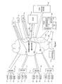
- FIG. 1 illustrates a telecommunications access network according to a first preferred embodiment of the present invention.
- the network is arranged in a known manner - see for example the present Applicant's earlier patent applications published with publication Numbers WO 2007/012867 & WO 2009/122137 the contents of which are incorporated herein by reference.
- a number of sets of Customer Premises Equipment (CPE) 11-13, 21-23, 31-33 are connected, via copper pair lines 1 (these correspond to the telecommunications lines as claimed) over which Asynchronous Digital Subscriber Line (ADSL) connections are established, to Digital Subscriber Line Access Multiplexors (DSLAMs) 51-54 (which constitute the aggregation devices as claimed in the present embodiment).
- ADSL Asynchronous Digital Subscriber Line
- DSL Digital Subscriber Line Access Multiplexors
- the DSLAMs have onward connections through the remainder of the access network towards the core network to permit data to be transmitted to and received from the core network, etc.
- these connections are not shown in Figure 1 since they are not relevant to the present embodiment which instead is concerned with the management of the DSLAMs 51-54 and the associated DSL connections 1.
- each of the DSLAMs is connected to a Management Network 60 via which it can communicate with a corresponding Data Collector (DC) (also known as an Element Manager) 71, 72, 73 (these constitute the data collector modules as claimed in the present embodiment).
- DC Data Collector
- These lines of communication are illustrated in Figure 1 by dashed lines 511, 521, 533, 543 illustrating lines of communication between DSLAMs 51 and 52 and DC 71 and between DSLAMs 53 and 54 and DC 73 respectively.
- the DCs periodically or from time to time collect (or are sent) performance/operational data from the DSLAMs about the respective DSLAM's respective DSL connections. The nature of this information (and the amount) is changing (and increasing) over time as access network technology develops.
- DSLAMs and Multi Service Access Nodes (MSANs) in access networks using these
- DCs Multi Service Access Nodes
- Examples of the type of information which may be produced by DSLAMs which may be used in the present embodiment are described in more detail below.
- the data collected by the DCs may be aggregated by the DC's (the extent to which any such aggregation is done is dependent upon the particular manufacturer and/or model of the device in question).
- the data is then periodically or from time to time transferred from each DC to the Dynamic Line Management module (DLM) 80 (this constitutes the Management module as claimed in the present embodiment), also via the management network 60; dotted lines 718 and 738 in Figure 1 illustrate lines of communication between DC 71 and DC 73 to the DLM 80 respectively over which the aggregated data from the DCs is transmitted to the DLM 80.
- DLM 80 is basically software which runs on a large server computer.
- the DLM of the present embodiment is modified from such a known management module in that it is additionally operable to interact with the File Check Console (FCC) 100 as indicated by the bidirectional dotted and dashed line 801.
- FCC File Check Console
- the FCC is operable to receive details from the DLM 80 abut what data it has received, to check this data against a database 106 (which it maintains locally in the present embodiment) and to identify any apparently missing data such that appropriate action can be taken to account for any such missing data.
- Such actions may include asking the device where the data appears to be missing form to resend the missing data, informing an engineer about the missing data to investigate what problem might be causing the data to go missing and modifying the operation of the management module 80 in order to account for the fact that the data is missing (e.g. to prevent moving a particular line to a less aggressive profile than necessary based on only a small amount of performance/operational data).
- the FCC 100 has an additional line of communication with a line provisioning and de-provisioning system 90 which forms a part of the Operational Support Systems (OSS) system of the access network illustrated in Figure 1 .
- This line of communication is illustrated in Figure 1 by the dotted line 901.
- the FCC additionally has a web interface which enables it to communicate with remote devices such as remote personal computer device 110 as illustrated by the dotted line 111 in Figure 1 .
- the web interface permits any suitably authorised remote user (or automated application) to send queries to the FCC and to receive responses to those queries, for example via a web browser which displays the data returned by the FCC to the user.
- the FCC 100 can be considered as comprising a processor subsystem 102, an Interface 104, a Line Status Database 106 and a memory 200 in which is stored the various programs required to run the FCC 100.
- the memory 200 additionally contains Line Status Database Code Means 210, Comparison Code Means 220 and Output Control Code means 230.
- the Line Status Database Code Means 210 controls the way in which the database 106 is updated in response to the receipt of data, whether it be from the DLM 80, the OSS provisioning/de-provisioning system 90, or indeed from an authorised user operating remote pc 110 via the web interface. In the present embodiment, all three interfaces to these three different systems are considered to go via the same physical interface 104 to the management network 60 (though of course separate physical interfaces could be used in alternative embodiments etc.).
- the Comparison Code Means 220 controls the way in which newly received data is compared with the expected data (as stored in the database 106) in order to ascertain if the database needs updating and if any action should be taken as a result of there being apparently missing data based on the comparison between received data and expected data, etc.
- the output control code means is responsible for taking any actions which need to be taken as a result of, for example, the comparison means identifying that some expected data is missing. For example, it may control the initiation of a request for missing data to be resent, or it may cause a message to be sent to a remote user via the web interface or for the response to any user requests for data to be highlighted in such a manner as to make the missing data appear more conspicuous, etc.
- Figure 3 presents the method as though it were performed sequentially. However, this is merely done for ease of description. It will be apparent that modern programming techniques tend to operate in a multi-threaded manner and often in a message based approach - (e.g. messages are received and then processed and the results of the processing returned to the element which initiated the message, etc.) - and the present embodiment uses these standard techniques in order to implement the functionality illustrated in Figure 3 .
- the FCC determines if it has received any line status data from the line provisioning / de-provisioning system 90 (this is in the present embodiment an inventory management system and it is able to provide initially a full data set of all of the lines in the access network which are to be managed by the DLM 80 and the FCC 100, and thereafter it provides to the FCC via communication line 901, details of any provisions, ceases or modifications (e.g. resulting from orders for such actions being fed into the OSS system)). If it has, the process moves to step s10 where the received data is compared with the data currently contained within the database 106 to see if an update to the database is required.
- the line provisioning / de-provisioning system 90 this is in the present embodiment an inventory management system and it is able to provide initially a full data set of all of the lines in the access network which are to be managed by the DLM 80 and the FCC 100, and thereafter it provides to the FCC via communication line 901, details of any provisions, ceases or modifications (e.g. resulting from
- the data which is reported by the OSS device 90 and (which is maintained in the database 160 in respect of each line) includes:
- step s15 it is ascertained whether or not an update is required. If the information received is more recent than the information contained in the database, the database has not already been amended to reflect the new information and the new information is different to what is currently contained in the database, then it is determined that an update is required and the process moves to step s20, whereas if no update is required the process proceeds directly to step s25. At step s20 the database 106 is accordingly updated under the control of the database maintenance code means 210 to reflect the newly received information.
- the FCC determines whether or not it has received new information (e.g. a report) from the management module, DLM 80. If so, the method proceeds to step s30 in which the FCC 100, under the control of the comparison code means 220, analyses the report to see if an update to the database is required.
- the DLM 80 sends two types of report to the FCC.
- the first type of report is sent whenever it (DLM 80) receives a report from a DC.
- This first type of report contains a listing of which DSLAMs have been included in the report received from the DC and may comprise a list of Comma Seperated Values (CSV) pairs of data comprising the DC ID and the DSLAM ID.
- CSV Comma Seperated Values
- DC 71 having, for example DC ID DC01 and it contains data received from DSLAMs 51 and 52 (having, for example IDs DSLAM01 and DSLAM02)
- DSLAMs 51 and 52 having, for example IDs DSLAM01 and DSLAM02
- the report from the DLM 80 to the FCC 100 might comprise a list as follows:
- each report from a DC is expected to be complete (i.e. to include data from all of the DSLAMs which it manages), from this report, the FCC can identify whether or not all of the DSLAMs which it expects to see in the report are included in the report or not. If some of the expected DSLAMs are not mentioned in the report which the FCC receives from the DLM 80 this will be identified in step s35.
- This first type of report is sent, in the present embodiment, each time the DLM 80 receives a report from the DC.
- the other type of report which the DLM 80 sends to the FCC in the present embodiment is a much more detailed report which is only sent once per 24 hour period.
- the report includes a CSV file containing a line for each circuit for which data has been received by the DLM, specifying how many bins of data were collected in respect of that circuit for the relevant 24 hour period. From this report, the FCC can identify if any DC's have completely failed to send a report, in which case, in the present embodiment, a request, for a resend of data from that DC to the DLM 80, is sent by the FCC directly to the DC in question over the management network 60.
- this information is stored in a table in the database 106 and is viewable by an engineer over the web interface in response to a suitable request for data (e.g. a request might ask for information about all circuits containing no information at all over a particular period, or all circuits containing less than 100% of the expected number of bins over a certain period etc.).
- the FCC stores within its database all of the received information, in particular identifying in respect of each DC whether or not a report has been received in respect of each report period (normally 24 hours), and also in respect of each DSLAM (or MSAN or other aggregation device) for the given report period, and also in respect of each circuit (also for that report period) and finally also in respect of each bin for each circuit (for a particular report period).
- step s35 the FCC determines at step s35 that some of the expected data for a given report period, in respect of either an entire DC or an entire DSLAM has not been received. If after updating the tables in this way the FCC determines at step s35 that some of the expected data for a given report period, in respect of either an entire DC or an entire DSLAM has not been received, then, in the present embodiment, the process proceeds to step s40 in which a message is sent back to the DLM 80 informing it that a report from either a DC or a DSLAM is missing and the DLM then sends a message back to the respective DC asking it to (re)send the missing information. Upon completion of step s40 the method proceeds to step s45. If all of the expected DC's and all of the expected DSLAMs have reported in the relevant report period, then the method proceeds straight from s35 to step s45.
- step s45 the FCC determines whether or not it has received a query via the web interface (e.g. from pc 110). Whenever a query is received it is responded to a step s50 in an appropriate manner. For example, the requester may be authorised and if the authorisation process succeeds the correct response will be obtained and sent to the requestor over the web interface. Upon completion of step s50 the method returns to step s5 to await any further inputs to the FCC.
- the FCC only receives reports directly from the DLM.
- the FCC could receive reports directly from DCs or even from DSLAMs.
- the data received may either by a direct copy of what is sent to the DLM (or to the DC in the case of DSLAMs or even MSANs, etc.) which has the advantage that it is less likely that there will be a discrepancy between what is actually sent to the DLM (or DC) and what the FCC is led to believe has been sent to the DLM (or DC), or alternatively, the DC (or DSLAM) could prepare a special report for the FCC which summarises the content which is actually sent to the DLM (or DC).
- the report could further specify for each DSLAM which has been incuded in the report, the number of circuits for which data has been reported.
- the expected number of circuits for a particular DSLAM is obtainable from the database 106 and so this information can be used to flag up DSLAMs which appear to be missing data from their reports to the DC (although the problem could of course lie with the DC and not the DSLAM - thus a preferred approach for dealing with a situation where a DSLAM appears to have omitted data may be to contact the DC which sent the report and point out that less than the total number of circuits appears to have been accounted for and asking the DC to re-obtain the information form the DSLAM in case some data was missing).
- re-send requests are automatically generated if the FCC determines that data from an entire DC or from an entire DSLAM/MSAN/aggregator device is missing, but not if data from a single circuit is missing.
- requests could be generated automatically even in respect of data missing from just a single circuit.
- no such requests could be automatically generated even if data is detected as being missing from an entire DC or DSLAM/aggregator device, etc. and instead the system could rely simply on an engineer examining the database and seeing that the data is missing from an entire DC, etc.
- the FCC could take further actions in response to detecting that data is missing.
Landscapes
- Engineering & Computer Science (AREA)
- Signal Processing (AREA)
- Environmental & Geological Engineering (AREA)
- Computer Networks & Wireless Communication (AREA)
- Telephonic Communication Services (AREA)
- Data Exchanges In Wide-Area Networks (AREA)
Priority Applications (3)
| Application Number | Priority Date | Filing Date | Title |
|---|---|---|---|
| EP10250612A EP2369785A1 (de) | 2010-03-26 | 2010-03-26 | Datensammlung in einem Zugangsnetzwerk |
| PCT/GB2011/000434 WO2011117590A1 (en) | 2010-03-26 | 2011-03-25 | Data collection in an access network |
| US13/637,590 US8811571B2 (en) | 2010-03-26 | 2011-03-25 | Data collection in an access network |
Applications Claiming Priority (1)
| Application Number | Priority Date | Filing Date | Title |
|---|---|---|---|
| EP10250612A EP2369785A1 (de) | 2010-03-26 | 2010-03-26 | Datensammlung in einem Zugangsnetzwerk |
Publications (1)
| Publication Number | Publication Date |
|---|---|
| EP2369785A1 true EP2369785A1 (de) | 2011-09-28 |
Family
ID=42288623
Family Applications (1)
| Application Number | Title | Priority Date | Filing Date |
|---|---|---|---|
| EP10250612A Ceased EP2369785A1 (de) | 2010-03-26 | 2010-03-26 | Datensammlung in einem Zugangsnetzwerk |
Country Status (3)
| Country | Link |
|---|---|
| US (1) | US8811571B2 (de) |
| EP (1) | EP2369785A1 (de) |
| WO (1) | WO2011117590A1 (de) |
Families Citing this family (2)
| Publication number | Priority date | Publication date | Assignee | Title |
|---|---|---|---|---|
| EP2437434A1 (de) * | 2010-09-30 | 2012-04-04 | British Telecommunications Public Limited Company | Überwachung des Datenverkehrs basierend auf Benutzerprofilen |
| US12477336B2 (en) * | 2023-01-06 | 2025-11-18 | Microsoft Technology Licensing, Llc | Collecting and managing access to management data in a telecommunications network |
Citations (5)
| Publication number | Priority date | Publication date | Assignee | Title |
|---|---|---|---|---|
| WO2006076518A2 (en) * | 2005-01-14 | 2006-07-20 | Sbc Knowledge Ventures, L.P. | Method and apparatus for managing a quality of service for a communication link |
| WO2007012867A1 (en) | 2005-07-29 | 2007-02-01 | British Telecommunications Public Limited Company | Method of operating apparatus for communicating data over a data network |
| WO2009010726A1 (en) | 2007-07-13 | 2009-01-22 | British Telecommunications Public Limited Company | Method and apparatus for communicating data over a data network |
| EP2107779A1 (de) * | 2008-03-31 | 2009-10-07 | British Telecmmunications public limited campany | Datenbankkommunikation |
| EP2169980A1 (de) * | 2008-09-30 | 2010-03-31 | BRITISH TELECOMMUNICATIONS public limited company | Dynamische Leitungsverwaltung |
Family Cites Families (2)
| Publication number | Priority date | Publication date | Assignee | Title |
|---|---|---|---|---|
| US7860221B2 (en) * | 2004-08-10 | 2010-12-28 | At&T Intellectual Property I, L.P. | Methods, systems and computer program products for inventory reconciliation |
| US7804939B2 (en) * | 2005-04-20 | 2010-09-28 | At&T Intellectual Property I, L.P. | Methods and systems for correcting cross-connect assignments |
-
2010
- 2010-03-26 EP EP10250612A patent/EP2369785A1/de not_active Ceased
-
2011
- 2011-03-25 US US13/637,590 patent/US8811571B2/en active Active
- 2011-03-25 WO PCT/GB2011/000434 patent/WO2011117590A1/en not_active Ceased
Patent Citations (6)
| Publication number | Priority date | Publication date | Assignee | Title |
|---|---|---|---|---|
| WO2006076518A2 (en) * | 2005-01-14 | 2006-07-20 | Sbc Knowledge Ventures, L.P. | Method and apparatus for managing a quality of service for a communication link |
| WO2007012867A1 (en) | 2005-07-29 | 2007-02-01 | British Telecommunications Public Limited Company | Method of operating apparatus for communicating data over a data network |
| WO2009010726A1 (en) | 2007-07-13 | 2009-01-22 | British Telecommunications Public Limited Company | Method and apparatus for communicating data over a data network |
| EP2107779A1 (de) * | 2008-03-31 | 2009-10-07 | British Telecmmunications public limited campany | Datenbankkommunikation |
| WO2009122137A1 (en) | 2008-03-31 | 2009-10-08 | British Telecommunications Public Limited Company | Data communication |
| EP2169980A1 (de) * | 2008-09-30 | 2010-03-31 | BRITISH TELECOMMUNICATIONS public limited company | Dynamische Leitungsverwaltung |
Also Published As
| Publication number | Publication date |
|---|---|
| WO2011117590A1 (en) | 2011-09-29 |
| US20130028392A1 (en) | 2013-01-31 |
| US8811571B2 (en) | 2014-08-19 |
Similar Documents
| Publication | Publication Date | Title |
|---|---|---|
| US7668943B2 (en) | Method for real-time synchronizing configuration data between element management systems and network elements | |
| US8792361B2 (en) | Dynamic line management of digital subscriber line connections | |
| CN103957144B (zh) | 对网络连接的监视 | |
| EP1995942B1 (de) | Verfahren und Modul zum Abrufen eines digitalen Teilnehmerleitungsparameters und Leitungsverwaltungssystem | |
| US20150222486A1 (en) | Dsl system | |
| EP1953959A1 (de) | Datenkommunikation | |
| CN106464766B (zh) | 控制接入网络的方法、接入网络节点 | |
| CN101981875A (zh) | 数据通信 | |
| JP4928546B2 (ja) | ユーザ嗜好ベースdslシステム | |
| CN112491623A (zh) | 用于预测成功的dsl线路优化的方法和装置 | |
| JP4928545B2 (ja) | ユーザ嗜好ベースdslシステム | |
| US7334038B1 (en) | Broadband service control network | |
| US6507565B1 (en) | Method and system for managing remote resources in a telecommunications system | |
| US8811571B2 (en) | Data collection in an access network | |
| EP2553871B1 (de) | Leistungsdatensammlung für die DSL Anschlüsse in einem Zugangsnetzwerk | |
| US20130194917A1 (en) | Apparatuses and methods for registering transmission capacities in a broadband access network | |
| EP2820800B1 (de) | Dynamic line management (dlm) von digital subscriber line (dsl) verbindungen | |
| EP2237462A1 (de) | Verfahren für dynamische Linien verwaltung DLM von DSL Verbindungen | |
| CN101800666A (zh) | 数字用户线端口信息收集方法及系统 | |
| KR101091478B1 (ko) | 비대칭 디지털 가입자 회선의 트래픽 분석 시스템 및 그방법 | |
| US20120054377A1 (en) | Method, apparatus and system for managing line between access device and terminal |
Legal Events
| Date | Code | Title | Description |
|---|---|---|---|
| PUAI | Public reference made under article 153(3) epc to a published international application that has entered the european phase |
Free format text: ORIGINAL CODE: 0009012 |
|
| AK | Designated contracting states |
Kind code of ref document: A1 Designated state(s): AT BE BG CH CY CZ DE DK EE ES FI FR GB GR HR HU IE IS IT LI LT LU LV MC MK MT NL NO PL PT RO SE SI SK SM TR |
|
| AX | Request for extension of the european patent |
Extension state: AL BA ME RS |
|
| STAA | Information on the status of an ep patent application or granted ep patent |
Free format text: STATUS: THE APPLICATION HAS BEEN REFUSED |
|
| 18R | Application refused |
Effective date: 20111027 |