EP2369802A2 - Signalzeugungsvorrichtung und -verfahren mit einem Übertragungsverfahren mit Fouriertransformation - Google Patents
Signalzeugungsvorrichtung und -verfahren mit einem Übertragungsverfahren mit Fouriertransformation Download PDFInfo
- Publication number
- EP2369802A2 EP2369802A2 EP11153971A EP11153971A EP2369802A2 EP 2369802 A2 EP2369802 A2 EP 2369802A2 EP 11153971 A EP11153971 A EP 11153971A EP 11153971 A EP11153971 A EP 11153971A EP 2369802 A2 EP2369802 A2 EP 2369802A2
- Authority
- EP
- European Patent Office
- Prior art keywords
- data
- time
- duplication
- fourier transform
- unit
- Prior art date
- Legal status (The legal status is an assumption and is not a legal conclusion. Google has not performed a legal analysis and makes no representation as to the accuracy of the status listed.)
- Granted
Links
Images



Classifications
-
- H—ELECTRICITY
- H04—ELECTRIC COMMUNICATION TECHNIQUE
- H04L—TRANSMISSION OF DIGITAL INFORMATION, e.g. TELEGRAPHIC COMMUNICATION
- H04L27/00—Modulated-carrier systems
- H04L27/26—Systems using multi-frequency codes
- H04L27/2601—Multicarrier modulation systems
- H04L27/2602—Signal structure
-
- H—ELECTRICITY
- H04—ELECTRIC COMMUNICATION TECHNIQUE
- H04L—TRANSMISSION OF DIGITAL INFORMATION, e.g. TELEGRAPHIC COMMUNICATION
- H04L27/00—Modulated-carrier systems
- H04L27/26—Systems using multi-frequency codes
- H04L27/2601—Multicarrier modulation systems
- H04L27/2626—Arrangements specific to the transmitter only
- H04L27/2627—Modulators
- H04L27/2634—Inverse fast Fourier transform [IFFT] or inverse discrete Fourier transform [IDFT] modulators in combination with other circuits for modulation
Definitions
- the present invention relates to a signal generation device and a signal generation method that impart characteristics of second-order cyclostationarity in a communication system that carries out signal identification based on second-order cyclostationarity.
- Second-order cyclostationarity refers to statistics that generate different characteristics for signals having different parameters, and the use thereof makes it possible to easily identify a plurality of signals having different communication methods.
- Second-order cyclostationarity refers to statistics that generate different characteristics for signals having different parameters, and the use thereof makes it possible to easily identify a plurality of signals having different communication methods.
- Preference describes a signal generation method in which an ID based on statistics is imparted to a radio signal.
- Paragraphs 64 to 73 of the specification of Reference 1 describe a radio signal generation method which imparts characteristics of cyclostationarity in a multicarrier transmission system by transmitting the same symbol for a plurality of predetermined subcarriers.
- Reference 2 describes a radio signal generation method which imparts characteristics of cyclostationarity by duplicating data transmitted by some of subcarriers at the time of the use of an OFDM (Orthogonal Frequency Division Multiplexing) system and controlling input to inverse Fourier transform to generate transmission signals such that the same data is transmitted by other subcarriers.
- OFDM Orthogonal Frequency Division Multiplexing
- the radio signal generation method in Reference 1 and the radio signal generation method in Reference 2 make the transmission signal of a certain carrier identical to a signal transmitted by a subcarrier distant from the relevant subcarrier by a predetermined number of subcarriers, thereby generating signals having characteristics of cyclostationarity corresponding to the predetermined number.
- the types of characteristics of cyclostationarity which can be imparted is limited by the total number of subcarriers, there was a problem in that it is difficult to transmit numerous types of information using characteristics of cyclostationarity.
- the invention has been finalized in order to solve the above-described problems, and an object of the invention is to provide a signal generation device and a signal generation method capable of imparting various characteristics of second-order cyclostationarity in a communication system which carries out signal identification based on second-order cyclostationarity.
- an aspect of the invention provides a signal generation device that employs a transmission method using inverse Fourier transform.
- the signal generation device includes: a modulation unit configured to modulate transmission data to obtain modulation data; a serial-parallel conversion unit configured to convert the modulation data input in series from the modulation unit to parallel data of a predetermined size smaller than the size of inverse Fourier transform; a duplication unit configured to select and duplicate all or a portion of the parallel data obtained by the serial-parallel conversion unit, to obtain duplication data; a first time-axis shift unit configured to shift input duplication data along the time axis to obtain time-axis shift data; and an inverse Fourier transform unit configured to carry out inverse Fourier transform on the parallel data obtained by the serial-parallel conversion unit and the time-axis shift data obtained by the first time-axis shift unit.
- the degree of freedom on the time axis can be provided, making it possible to impart various characteristics of second-order cyclostationarity in accordance with the shift amount along the time axis.
- the signal generation device may further include a shift amount control unit configured to control the shift amount in the first time-axis shift unit.
- a shift amount control unit configured to control the shift amount in the first time-axis shift unit.
- the signal generation device may further include: a phase rotation unit configured to rotate the phase of a signal point at a predetermined rate for the duplication data duplicated by the duplication unit and output the duplication data with the phase rotated to the first time-axis shift unit; and a rotation rate control unit configured to control the rotation rate at which the phase of the signal point is rotated by the phase rotation unit.
- a frequency shift amount corresponding to the rotation rate at which the phase of the signal point is rotated is set as an additional variation factor, making it possible to impart various characteristics of cyclostationarity.
- the first time-axis shift unit may be configured to shift the duplication data along the time axis in terms of samples by applying phase rotation, which differs between subcarriers, to information symbols transmitted by subcarriers in the same symbol for the duplication data duplicated by the duplication unit.
- the signal generation device includes: a modulation unit configured to modulate transmission data to obtain modulation data; a serial-parallel conversion unit configured to convert the modulation data input in series from the modulation unit to parallel data of a predetermined size smaller than the size of inverse Fourier transform; a duplication unit configured to select and duplicate all or a portion of the parallel data obtained by the serial-parallel conversion unit, to obtain duplication data; an inverse Fourier transform unit configured to carry out inverse Fourier transform on the parallel data obtained by the serial-parallel conversion unit and the duplication data obtained by the duplication unit; a second time-axis shift unit configured to circularly shift samples after inverse Fourier transform of duplication data to obtain time-axis shift data shifted along the time axis in terms of samples; and a synthesis unit configured to synthesize the time-
- samples after inverse Fourier transform of the duplication data are circularly shifted to obtain time-axis shift data shifted along the time axis in terms of samples, and the time-axis shift data and data after inverse Fourier transform of the parallel data are synthesized, making it possible to impart various characteristics of second-order cyclostationarity in accordance with the shift amount along the time axis in terms of samples.
- the invention relating to the above-described signal generation device can also be grasped to be an invention relating to a signal generation method and can be described as follows.
- the invention relating to the signal generation method demonstrates the same actions and effects as the invention relating to the above-described signal generation device.
- the signal generation method includes: a modulation step of modulating transmission data to obtain modulation data; a serial-parallel conversion step of converting the modulation data obtained in the modulation step to parallel data of a predetermined size smaller than the size of inverse Fourier transform; a duplication step of selecting and duplicating all or a portion of the parallel data obtained in the serial-parallel conversion step, to obtain duplication data; a first time-axis shift step of shifting input duplication data along the time axis to obtain time-axis shift data; and an inverse Fourier transform step of carrying out inverse Fourier transform on the parallel data obtained in the serial-parallel conversion step and the time-axis shift data obtained in the first time-axis shift step.
- the signal generation method may further include a shift amount control step of controlling the shift amount in the first time-axis shift step.
- the signal generation method may further include: a phase rotation step of rotating the phase of a signal point at a predetermined rate for the duplication data duplicated in the duplication step and outputting the duplication data with the phase rotated to the first time-axis shift step; and a rotation rate control step of controlling the rotation rate at which the phase of the signal point is rotated in the phase rotation step.
- the signal generation device may shift the duplication data along the time axis in terms of samples by applying phase rotation, which differs between subcarriers, to information symbols transmitted by subcarriers in the same symbol for the duplication data duplicated by the duplication unit.
- the signal generation method includes: a modulation step of modulating transmission data to obtain modulation data; a serial-parallel conversion step of converting the modulation data obtained in the modulation step to parallel data of a predetermined size smaller than the size of inverse Fourier transform; a duplication step of selecting and duplicating all or a portion of the parallel data obtained in the serial-parallel conversion step, to obtain duplication data; an inverse Fourier transform step of carrying out inverse Fourier transform on the parallel data obtained in the serial-parallel conversion step and the duplication data obtained in the duplication step; a second time-axis shift step of circularly shifting samples after inverse Fourier transform of the duplication data to obtain time-axis shift data shifted along the time axis in terms of samples; and a synthesis step of synthesizing the time-axis shift data and data after inverse Fourier transform of the parallel data.
- Fig. 1 is a block diagram showing the functional configuration of a signal generation device according to a first and fourth embodiment.
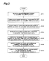
- Fig. 2 is a flowchart showing signal generation processing according to the first and fourth embodiment.
- Fig. 3 is a diagram illustrating the effects of signal generation processing according to the first embodiment.
- Fig. 4 is a block diagram showing the functional configuration of a signal generation device according to a modification of the first embodiment.
- Fig. 5 is a block diagram showing the functional diagram of a signal generation device according to a second embodiment.
- Fig. 6 is a flowchart showing signal generation processing according to the second embodiment.
- Fig. 7 is a block diagram showing the functional configuration of a signal generation device according to a third embodiment.
- Fig. 8 is a flowchart showing signal generation processing according to the third embodiment.
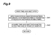
- Fig. 9 is a flowchart showing processing of a first time-axis shift step according to a fourth embodiment.
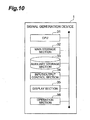
- Fig. 10 is a block diagram showing an example of the hardware configuration of a signal generation device.
- Fig. 1 is a block diagram showing the functional configuration of a signal generation device 1 according to the first embodiment.
- the signal generation device 1 includes a modulation unit 10, a serial-parallel conversion unit 11, a duplication unit 12, a first time-axis shift unit 13, an inverse Fourier transform unit 14, a GI insertion unit 15, and a parallel-serial conversion unit 16.
- the modulation unit 10 modulates data A to be transmitted (hereinafter, referred to as "transmission data A") to obtain modulation data.
- modulation refers to a technique for mapping transmission data on a signal space constituted by an in-phase component and an orthogonal component in accordance with a modulation method, such as phase modulation (BPSK, QPSK, or the like), amplitude modulation (PAM or the like), or quadrature amplitude modulation (QAM).
- the serial-parallel conversion unit 11 parallel-converts the modulation data obtained by and output in series from the modulation unit 10 to generate parallel data.
- the duplication unit 12 duplicates all or a portion of row data of a matrix given as the parallel data, to obtain duplication data.
- the first time-axis shift unit 13 shifts input duplication data along the time axis to obtain time-axis shift data.
- the first time-axis shift unit 13 stores a shift amount corresponding to a predefined imparted statistic in advance and shifts the duplication data along the time axis on the basis of the shift amount.
- the inverse Fourier transform unit 14 receives the parallel data output from the serial-parallel conversion unit 11 and the time-axis shift data output from the first time-axis shift unit 13 as an input, carries out inverse Fourier transform on the input signal, and outputs an obtained inverse Fourier transform signal.
- the GI insertion unit 15 duplicates all elements in a predetermined number of rows from the rightmost (or the leftmost) of the matrix of the inverse Fourier transform signal and connects the duplicated elements to the inverse Fourier transform signal from the left (or right) in the row direction to insert a guard interval (GI), thereby obtaining a GI insertion signal.
- the parallel-serial conversion unit 16 converts the matrix input as the GI insertion signal to serial data and outputs an obtained transmission signal B.
- signal generation processing processing based on a signal generation method according to an aspect of the invention, which is executed by the signal generation device 1 of the first embodiment.
- Fig. 2 shows a procedure relating to signal generation processing in the signal generation device 1.
- the modulation unit 10 of the signal generation device 1 modulates transmission data A to acquire modulation data (Step S11 of Fig. 2 : modulation step).
- Modulation data is input to the serial-parallel conversion unit 11 in series.
- the serial-parallel conversion unit 11 parallel-converts the modulation data input in series to acquire parallel data (Step S 12: serial-parallel conversion step).
- Acquired parallel data is input to the duplication unit 12 and also to the inverse Fourier transform unit 14 through the duplication unit 12.
- the duplication unit 12 duplicates all or a portion of row data of the input parallel data to acquire duplication data (Step S13: duplication step).
- Step S14 first time-axis shift step.
- Acquired time-axis shift data is input to the inverse Fourier transform unit 14.
- the inverse Fourier transform unit 14 carries out fast inverse Fourier transform (IFFT) on the input parallel data and the time-axis shift data to acquire an inverse Fourier transform signal (Step S15: inverse Fourier transform step).
- the acquired inverse Fourier transform signal is input to the GI insertion unit 15.
- the GI insertion unit 15 inserts a GI (guard interval) into the inverse Fourier transform signal to acquire a GI insertion signal (Step S16).
- the acquired GI insertion signal is input to the parallel-serial conversion unit 16 in parallel.
- the parallel-serial conversion unit 16 serial-converts the GI insertion signal input in parallel to acquire and output a transmission signal B as a time domain signal (Step S17).
- second-order cyclostationarity refers to a property mainly represented by a second-order cyclic autocorrelation function (CAF) and SCD (spectral correlation density).
- CAF second-order cyclic autocorrelation function
- SCD spectral correlation density
- CAF cyclic autocorrelation function
- the first time-axis shift unit 13 shifts the duplication data (duplicated symbols) along the time axis by one symbol, as shown in Fig. 3 , samples marked with an arrow D have correlation. If the transmission signal B is received and CAF relating to the transmission signal B is calculated, when ⁇ in the above-described formula (1) is equal to the frequency interval between a duplication source and a duplication destination, and ⁇ is equal to a time shift amount corresponding to a shifted symbol time (in this case, one symbol), a CAF peak pattern appears.
- the degree of freedom on the time axis can be provided, making it possible to impart various characteristics of second-order cyclostationarity in accordance with a shift amount along the time axis.
- a shift amount control unit 17 is provided in the signal generation device 1.
- the shift amount control unit 17 calculates a shift amount along the time axis in accordance with information of an imparted statistic C input from the outside and outputs the calculation result to the first time-axis shift unit 13.
- the first time-axis shift unit 13 carries out an operation to shift the duplication data along the time axis by the shift amount corresponding to the calculation result.
- This sequence of operations corresponds to a shift amount control step.
- characteristics of cyclostationarity which will appear vary in accordance with a control signal and the like from the outside including information of the imparted statistic C, making it possible to impart various characteristics of second-order cyclostationarity.
- Fig. 5 is a block diagram showing the functional configuration of a signal generation device 1 according to the second embodiment.
- the signal generation device 1 includes a modulation unit 10, a serial-parallel conversion unit 11, a duplication unit 12, a first time-axis shift unit 13, an inverse Fourier transform unit 14, a GI insertion unit 15, a parallel-serial conversion unit 16, a shift amount control unit 17, a rotation rate control unit 18, and a phase rotation unit 19.
- the modulation unit 10 modulates transmission data A to obtain modulation data.
- modulation refers to a technique for mapping transmission data on a signal space constituted by an in-phase component and an orthogonal component in accordance with a modulation method, such as phase modulation (BPSK, QPSK, or the like), amplitude modulation (PAM or the like), or quadrature amplitude modulation (QAM).
- the serial-parallel conversion unit 11 parallel-converts the modulation data obtained by and output in series from the modulation unit 10 to generate parallel data.
- the duplication unit 12 duplicates all or a portion of row data of a matrix given as the parallel data, to obtain duplication data.
- the phase rotation unit 19 multiplies each row of duplication data by a phase rotator, which undergoes phase rotation at a predetermined angular velocity, to obtain phase rotation data.
- the rotation rate control unit 18 controls the rotation rate of phase rotation in the phase rotation unit 19. That is, the rotation rate control unit 18 calculates the rotation rate of phase rotation in the phase rotation unit 19 in accordance with the input imparted statistic C and outputs the calculation result to the phase rotation unit 19.
- the phase rotation unit 19 carries out an operation to rotate the phase on that basis of the calculated rotation rate. This sequence of operations corresponds to a rotation rate control step.
- the first time-axis shift unit 13 shifts the input duplication data after phase rotation along the time axis to obtain time-axis shift data.
- the inverse Fourier transform unit 14 receives the parallel data output from the serial-parallel conversion unit 11 and the time-axis shift data output from the first time-axis shift unit 13 as an input, carries out inverse Fourier transform on the input signal, and outputs an obtained inverse Fourier transform signal.
- the GI insertion unit 15 duplicates all elements in a predetermined number of rows from the rightmost (or the leftmost) of the matrix of the inverse Fourier transform signal and connects the duplicated elements to the inverse Fourier transform signal from the left (or right) in the row direction to insert a guard interval (GI), thereby obtaining a GI insertion signal.
- the parallel-serial conversion unit 16 converts the matrix input as the GI insertion signal to serial data and outputs an obtained transmission signal B.
- the shift amount control unit 17 controls the shift amount in the first time-axis shift unit 13. That is, the shift amount control unit 17 calculates the shift amount in the first time-axis shift unit 13 in accordance with the input information of the imparted statistic C and outputs the calculation result to the first time-axis shift unit 13. Thus, the first time-axis shift unit 13 carries out an operation to shift duplication data along the time axis by the shift amount corresponding to the calculation result. This sequence of operations corresponds to a shift amount control step.
- Fig. 6 shows a procedure relating to signal generation processing in the signal generation device 1.
- the modulation unit 10 of the signal generation device 1 modulates transmission data A to acquire modulation data (Step S21 of Fig. 6 : modulation step).
- Modulation data is input to the serial-parallel conversion unit 11 in series.
- the serial-parallel conversion unit 11 parallel-converts the modulation data input in series to acquire parallel data (Step S22: serial-parallel conversion, step).
- Acquired parallel data is input to the duplication unit 12 and also to the inverse Fourier transform unit 14 through the duplication unit 12.
- the duplication unit 12 duplicates all or a portion of row data of the input parallel data to acquire duplication data (Step S23: duplication step).
- Acquired duplication data is input to the phase rotation unit 13.
- the phase rotation unit 13 rotates the phase of signals of the duplication data at a predetermined angular velocity to acquire phase rotation data (Step S24: phase rotation step).
- Acquired phase rotation data is input to the first time-axis shift unit 13.
- the first time-axis shift unit 13 shifts the input phase rotation data (that is, duplication data after phase rotation) along the time axis to acquire time-axis shift data (Step S25: first time-axis shift step).
- Acquired time-axis shift data is input to the inverse Fourier transform unit 14.
- the inverse Fourier transform unit 14 carries out fast inverse Fourier transform (IFFT) on the input parallel data and the time-axis shift data to acquire an inverse Fourier transform signal (Step S26: inverse Fourier transform step).
- IFFT fast inverse Fourier transform
- the acquired inverse Fourier transform signal is input to the GI insertion unit 15.
- the GI insertion unit 15 inserts a GI (guard interval) into the inverse Fourier transform signal to acquire a GI insertion signal (Step S27).
- the acquired GI insertion signal is input to the parallel-serial conversion unit 16 in parallel.
- the parallel-serial conversion unit 16 serial-converts the GI insertion signal input in parallel to acquire and output a transmission signal B as a time domain signal (Step S28).
- Fig. 7 is a block diagram showing the functional configuration of a signal generation device 1 according to the third embodiment.
- the signal generation device 1 includes a modulation unit 10, a serial-parallel conversion unit 11, a duplication unit 12, inverse Fourier transform units 14A and 14B, a GI insertion unit 15, a parallel-serial conversion unit 16, a shift amount control unit 17, a zero-padding unit 20, and a second time-axis shift unit 21.
- the modulation unit 10 modulates transmission data A to obtain modulation data.
- modulation refers to a technique for mapping transmission data on a signal space constituted by an in-phase component and an orthogonal component in accordance with a modulation method, such as phase modulation (BPSK, QPSK, or the like), amplitude modulation (PAM or the like), or quadrature amplitudes modulation (QAM).
- the serial-parallel conversion unit 11 parallel-converts the modulation data obtained by and output in series from the modulation unit 10, to generate parallel data.
- the duplication unit 12 selects all or a portion of row data of a matrix given as the parallel data and duplicates the selected parallel data to obtain duplication data.
- the inverse Fourier transform units 14A and 14B receive the parallel data output from the serial-parallel conversion unit 11 and the time-axis shift data output from the first time-axis shift unit 13 as an input, carries out inverse Fourier transform on the input signal, and outputs an obtained inverse Fourier transform signal.
- the zero-padding unit 20 carries out processing for burying zero in the input signal (the parallel data and the time-axis shift data) which will be subjected to inverse Fourier transform in the inverse Fourier transform units 14A and 14B.
- duplication data of the selected parallel data is input from the duplication unit 12 to the inverse Fourier transform unit 14B, and data in which zero is buried in a row not selected in the duplication unit 12 is input from the zero-padding unit 20 to the inverse Fourier transform unit 14B.
- the inverse Fourier transform unit 14B carries out inverse Fourier transform on the input signal (that is, the zero-padded duplication data) having the duplication data of the selected row and the data of the row with zero buried.
- the parallel data (in this case, data of an unselected row in the matrix given as parallel data) which is not selected as a duplication target in the duplication unit 12 is input from the duplication unit 12 to the inverse Fourier transform unit 14A, and the data in which zero is buried in the row selected in the duplication unit 12 is input from the zero-padding unit 20 to the inverse Fourier transform unit 14A.
- the inverse Fourier transform unit 14A carries out inverse Fourier transform on the input signal (that is, the zero-padded parallel data) having the parallel data of the unselected row and data of the row (selected row) with zero buried.
- parallel data of all the rows may be input from the duplication unit 12 to the inverse Fourier transform unit 14A, and the inverse Fourier transform unit 14A may substitute the data of the row selected in the duplication unit 12 from among the parallel data of all the rows with zero to form the same zero-padded parallel data as described above and may carry out inverse Fourier transform on the zero-padded parallel data.
- the second time-axis shift unit 21 shifts the inverse Fourier transform signal output from the inverse Fourier transform unit 14B along the time axis. Specifically, the second time-axis shift unit 21 circularly shifts the samples of the inverse Fourier transform signal to acquire time-axis shift data shifted along the time axis in terms of samples.
- the shift amount control unit 17 controls the shift amount in the second time-axis shift unit 21. That is, the shift amount control unit 17 calculates the shift amount in the second time-axis shift unit 21 in accordance with input information of the imparted statistic C and outputs the calculation result to the second time-axis shift unit 21.
- the second time-axis shift unit 21 carries out an operation to shift the inverse Fourier transform signal from the inverse Fourier transform unit 14B along the time axis by the shift amount corresponding to the calculation result.
- the shift amount control unit 17 may not be provided in the signal generation device 1, and the second time-axis shift unit 21 may store a shift amount corresponding to a predefined imparted statistic in advance and may execute a shift along the time axis on the basis of the shift amount.
- the synthesis unit 22 synthesizes the inverse Fourier transform signal output from the inverse Fourier transform unit 14A and the inverse Fourier transform signal after the shift in the second time-axis shift unit 21.
- the GI insertion unit 15 duplicates all elements in a predetermined number of rows from the rightmost (or the leftmost) of the matrix of the inverse Fourier transform signal and connects the duplicated elements to the inverse Fourier transform signal from the left (or right) in the row direction to insert a guard interval (GI), thereby obtaining a GI insertion signal.
- the parallel-serial conversion unit 16 converts the matrix input as the GI insertion signal to serial data and outputs an obtained transmission signal B.
- Fig. 8 shows a procedure relating to signal generation processing in the signal generation device 1.
- the modulation unit 10 of the signal generation device 1 modulates transmission data A to acquire modulation data (Step S31 of Fig. 8 : modulation step).
- the modulation data is input to the serial-parallel conversion unit 11 in series.
- the serial-parallel conversion unit 11 parallel-converts the modulation data input in series to acquire parallel data (Step S32: serial-parallel conversion step).
- the acquired parallel data is input to the duplication unit 12 and also to the inverse Fourier transform unit 14 through the duplication unit 12.
- the duplication unit 12 selects all or a portion of row data of a matrix given as parallel data and duplicates the selected parallel data to acquire duplication data (Step S33: duplication step).
- the duplication data of the selected parallel data (in this case, data of the selected row in the matrix given as parallel data) is input from the duplication unit 12 to the inverse Fourier transform unit 14B, and data of a row in which zero is buried in the parallel data not selected in the duplication unit 12 is input from the zero-padding unit 20 to the inverse Fourier transform unit 14B.
- the inverse Fourier transform unit 14B carries out inverse Fourier transform on the input signal (that is, zero-padded duplication data) having the duplication data of the selected row and the data of the row (unselected row) with zero buried (Step S34: inverse Fourier transform step).
- Step S34 the parallel data (in this case, data of an unselected row in the matrix given as parallel data) not selected as a duplication target in the duplication unit 12 is input from the duplication unit 12 to the inverse Fourier transform unit 14A, and the data of the row in which zero is buried in the parallel data (in this case, data of the selected row) not selected in the duplication unit 12 is input from the zero-padding unit 20 to the inverse Fourier transform unit 14A.
- the inverse Fourier transform unit 14A carries out inverse Fourier transform on the input signal (that is, zero-padded parallel data having the parallel data of the unselected row and the data of the row (selected row) with zero buried.
- the second time-axis shift unit 21 circularly shifts the samples of the inverse Fourier transform signal to acquire time-axis shift data (that is, an inverse Fourier transform signal after the shift is executed) shifted along the time axis in terms of samples (Step S35: second time-axis shift step).
- the synthesis unit 22 synthesizes the inverse Fourier transform signal output from the inverse Fourier transform unit 14A and the inverse Fourier transform signal after the shift is executed in the second time-axis shift unit 21 to acquire a synthesis signal (Step S36: synthesis step).
- the acquired synthesis signal is input to the GI insertion unit 15.
- the GI insertion unit 15 inserts a GI (guard interval) into the synthesis signal to acquire a GI insertion signal (Step S37).
- the acquired GI insertion signal is input to the parallel-serial conversion unit 16 in parallel.
- the parallel-serial conversion unit 16 serial-converts the GI insertion signal input in parallel to acquire and output a transmission signal B as a time domain signal (Step S38). With the above, the signal generation processing ends.
- the inventors have considered that "the samples of a signal after inverse Fourier transform are circularly shifted" corresponds to "phase rotation of symbols on the frequency axis".
- the number of subcarriers is N
- the phase rotation amount which should be given to an m-th subcarrier so as to be equivalent to a time shift when the number of samples is i is expressed by the following formula (2).
- Phase rotation amount which should be given to them - the subcarrier exp - j ⁇ 2 ⁇ ⁇ im / N
- the inventors have considered a fourth embodiment described below as the configuration for realizing a shift along the time axis in terms of samples on the basis of the above-described finding.
- the processing which is executed by the first time-axis shift unit 13 is different from the first embodiment. That is, in the fourth embodiment, the first time-axis shift unit 13 applies phase rotation which differs between subcarriers, to information symbols transmitted by the respective subcarriers in the same symbol for duplication data duplicated by the duplication unit 12, thereby shifting the duplication data along the time axis in terms of samples.
- Step S14 first time-axis shift step
- the processing content in Step S14 (first time-axis shift step) of Fig. 2 is different from that of the first embodiment. That is, the first time-axis shift unit 13 applies phase rotation which differs between subcarriers, to information symbols transmitted by the respective subcarriers in the same symbol for duplication data duplicated by the duplication unit 12 (Step S41 of Fig. 9 ), thereby obtaining time-axis shift data shifted along the time axis in terms of samples (Step S42).
- phase rotation which differs between subcarriers, is applied to information symbols transmitted by the respective subcarriers in the same symbol, thereby acquiring the time-axis shift data shifted along the time axis in terms of samples. Therefore, it is possible to impart various characteristics of cyclostationarity.
- the invention is not limited to a signals generation device that employs the OFDM system and may be applied to all types of signal generation devices that employ a transmission method using inverse Fourier transform.
- the invention may be applied to a signal generation device that employs an SC-FDMA (Single-Carrier FDMA) system.
- SC-FDMA Single-Carrier FDMA
- the second embodiment corresponds to an example where, in the first embodiment (a time shift in terms of symbol time), a CAF peak position shift in the frequency direction is also applied by applying phase rotation which is common to the subcarriers. In this way, it is very effective that phase rotation for the CAF peak position shift in the frequency direction is added to the time shift.
- the CAF peak position shift in the frequency direction may also be applied by applying phase rotation which is common to the subcarriers, making it possible to impart various characteristics of cyclostationarity.
- an application example to the fourth embodiment corresponds to an example where phase rotation which differs between the subcarriers is applied to realize a time shift in terms of samples, and phase rotation which is common to the carriers is applied to realize the CAF peak position shift in the frequency direction.
- the hardware configuration of the signal generation device 1 according to each of the first to fourth embodiments may be constituted by a computer system which is capable of storing data or other arbitrary devices.
- the signal generation device 1 may include: a CPU 31 which executes an operating system, an application program, or the like; a main storage section 32 which is constituted by a ROM and a RAM; an auxiliary storage section 33 which is constituted by a nonvolatile memory or the like; an input/output control section 34 which controls data input/output with respect to the outside; a display section 35 which is constituted by a monitor or the like; and an operation section 36 which is constituted keys for inputting letters and numerals and for instructing execution.
Landscapes
- Engineering & Computer Science (AREA)
- Computer Networks & Wireless Communication (AREA)
- Signal Processing (AREA)
- Physics & Mathematics (AREA)
- Discrete Mathematics (AREA)
- General Physics & Mathematics (AREA)
- Mathematical Physics (AREA)
- Transmitters (AREA)
- Digital Transmission Methods That Use Modulated Carrier Waves (AREA)
- Mobile Radio Communication Systems (AREA)
- Complex Calculations (AREA)
- Compression, Expansion, Code Conversion, And Decoders (AREA)
Applications Claiming Priority (1)
| Application Number | Priority Date | Filing Date | Title |
|---|---|---|---|
| JP2010072967A JP4916561B2 (ja) | 2010-03-26 | 2010-03-26 | 信号生成装置及び信号生成方法 |
Publications (3)
| Publication Number | Publication Date |
|---|---|
| EP2369802A2 true EP2369802A2 (de) | 2011-09-28 |
| EP2369802A3 EP2369802A3 (de) | 2017-04-12 |
| EP2369802B1 EP2369802B1 (de) | 2018-02-28 |
Family
ID=44202842
Family Applications (1)
| Application Number | Title | Priority Date | Filing Date |
|---|---|---|---|
| EP11153971.4A Active EP2369802B1 (de) | 2010-03-26 | 2011-02-10 | Signalzeugungsvorrichtung und -verfahren mit einem übertragungsverfahren mit fouriertransformation |
Country Status (4)
| Country | Link |
|---|---|
| US (1) | US8542758B2 (de) |
| EP (1) | EP2369802B1 (de) |
| JP (1) | JP4916561B2 (de) |
| CN (1) | CN102202023B (de) |
Families Citing this family (6)
| Publication number | Priority date | Publication date | Assignee | Title |
|---|---|---|---|---|
| JP5782989B2 (ja) * | 2011-10-26 | 2015-09-24 | アイコム株式会社 | 通信機および通信方法 |
| JP5699913B2 (ja) * | 2011-11-21 | 2015-04-15 | アイコム株式会社 | 通信機および通信方法 |
| US8947998B2 (en) * | 2011-12-20 | 2015-02-03 | Lg Electronics Inc. | Method and apparatus for detecting radio signal |
| JP6429663B2 (ja) * | 2015-02-12 | 2018-11-28 | ルネサスエレクトロニクス株式会社 | 脈拍計、周波数解析装置及び脈拍測定方法 |
| CN112187333B (zh) * | 2019-07-05 | 2022-06-14 | 华为技术有限公司 | 信号传输方法及其装置 |
| JP7647436B2 (ja) | 2021-08-11 | 2025-03-18 | 株式会社デンソー | 信号生成装置、信号生成プログラムおよび信号生成方法 |
Citations (1)
| Publication number | Priority date | Publication date | Assignee | Title |
|---|---|---|---|---|
| US20080026704A1 (en) | 2006-07-31 | 2008-01-31 | Ntt Docomo, Inc. | Wireless transmitter, wireless receiver, wireless communication system, and wireless signal control method |
Family Cites Families (6)
| Publication number | Priority date | Publication date | Assignee | Title |
|---|---|---|---|---|
| KR20040005175A (ko) * | 2002-07-08 | 2004-01-16 | 삼성전자주식회사 | 직교주파수분할다중화 통신시스템에서 선택적매핑의부가정보 송수신 장치 및 방법 |
| EP1533968B1 (de) * | 2003-11-11 | 2010-08-25 | NTT DoCoMo, Inc. | Signalempfangsgerät und Empfangszeiterkennungsverfahren |
| US7738356B2 (en) * | 2005-06-28 | 2010-06-15 | Broadcom Corporation | Multiple stream cyclic-shifted delay transmitter |
| US8059524B2 (en) * | 2008-01-04 | 2011-11-15 | Texas Instruments Incorporated | Allocation and logical to physical mapping of scheduling request indicator channel in wireless networks |
| JP4729591B2 (ja) * | 2008-02-13 | 2011-07-20 | 株式会社エヌ・ティ・ティ・ドコモ | 非再生型無線中継装置、無線通信システム及び無線信号中継方法 |
| JP5167097B2 (ja) * | 2008-12-03 | 2013-03-21 | 株式会社エヌ・ティ・ティ・ドコモ | 信号生成装置及び信号生成方法 |
-
2010
- 2010-03-26 JP JP2010072967A patent/JP4916561B2/ja active Active
-
2011
- 2011-02-10 EP EP11153971.4A patent/EP2369802B1/de active Active
- 2011-03-01 US US13/037,933 patent/US8542758B2/en active Active
- 2011-03-25 CN CN2011100736401A patent/CN102202023B/zh active Active
Patent Citations (1)
| Publication number | Priority date | Publication date | Assignee | Title |
|---|---|---|---|---|
| US20080026704A1 (en) | 2006-07-31 | 2008-01-31 | Ntt Docomo, Inc. | Wireless transmitter, wireless receiver, wireless communication system, and wireless signal control method |
Non-Patent Citations (1)
| Title |
|---|
| P. D. SUTTON; K. E. NOLAN; L. E. DOYLE: "Cyclostationary Signatures in Practical Cognitive Radio Applications", IEEE JOURNAL ON SELECTED AREAS IN COMMUNICATIONS (JSAC), vol. 26, no. 1, 2008, pages 13 - 24, XP011199414 |
Also Published As
| Publication number | Publication date |
|---|---|
| CN102202023A (zh) | 2011-09-28 |
| US8542758B2 (en) | 2013-09-24 |
| US20110235740A1 (en) | 2011-09-29 |
| EP2369802B1 (de) | 2018-02-28 |
| JP2011205557A (ja) | 2011-10-13 |
| CN102202023B (zh) | 2013-11-13 |
| EP2369802A3 (de) | 2017-04-12 |
| JP4916561B2 (ja) | 2012-04-11 |
Similar Documents
| Publication | Publication Date | Title |
|---|---|---|
| JP5167097B2 (ja) | 信号生成装置及び信号生成方法 | |
| EP2369802B1 (de) | Signalzeugungsvorrichtung und -verfahren mit einem übertragungsverfahren mit fouriertransformation | |
| US9319168B2 (en) | Transmitting apparatus, receiving apparatus, communication system, and communication method | |
| EP3174258A1 (de) | Verfahren und vorrichtung zur erzeugung und verarbeitung eines fdmw-signals | |
| US20110013716A1 (en) | Time-Frequency Space Constructions of Families of Signals | |
| JP2021136657A (ja) | Otfs変調を用いた通信において高精度化されたチャネル推定手法を用いる送信装置、受信装置、通信方法、およびベースバンドチップ | |
| US9344315B2 (en) | Transmitting system and receiving system, and transmitting method and receiving method | |
| JP7189684B2 (ja) | フロントエンド回路、テストボード、テストシステム、コンピュータおよびプログラム | |
| JP5794163B2 (ja) | 通信機および通信方法 | |
| Yuan et al. | WFRFT modulation recognition based on HOC and optimal order searching algorithm | |
| Yang et al. | A novel multi-carrier order division multi-access communication system based on TDCS with fractional Fourier transform scheme | |
| Hassan | Increasing the symbol rate in QAM system using a new set of orthonormal basics functions | |
| CN109391580A (zh) | 同步装置及同步方法 | |
| KR101215932B1 (ko) | 부가적 맵핑 시퀀스를 이용한 직교 주파수 분할 다중화 시스템의 최대전력 대 평균전력 비 감소 방법 및 이를 위한 장치 | |
| JP2014154968A (ja) | 通信機および通信方法 | |
| US8891644B2 (en) | Communication apparatus and communication method | |
| Guimarães | Complex envelope based modems: A tutorial | |
| US10756936B2 (en) | Signal transmitting apparatus | |
| CN106921604B (zh) | Fbmc发送信号生成方法及装置 | |
| JP2005020453A (ja) | 送信装置 | |
| Liang et al. | A Comparison of the Multicarrier Modulations in Underwater Acoustic Channels | |
| Abdulhussein et al. | Implementation of Filter Bank Multicarrier Transmitter Using Universal Software Radio Peripheral | |
| El-Amine | 6G Waveform Design for Integrated Sensing and Communication | |
| Mahmoud et al. | Peak Average Power Ratio Reduction in OFDM System with Smart Jamming for Cognitive Radio | |
| Ivoylovskaya et al. | APPLICATION OF CONSTELLATION CONSTELLATIONS IN DATA TRANSMISSION SYSTEMS |
Legal Events
| Date | Code | Title | Description |
|---|---|---|---|
| PUAI | Public reference made under article 153(3) epc to a published international application that has entered the european phase |
Free format text: ORIGINAL CODE: 0009012 |
|
| 17P | Request for examination filed |
Effective date: 20110301 |
|
| AK | Designated contracting states |
Kind code of ref document: A2 Designated state(s): AL AT BE BG CH CY CZ DE DK EE ES FI FR GB GR HR HU IE IS IT LI LT LU LV MC MK MT NL NO PL PT RO RS SE SI SK SM TR |
|
| AX | Request for extension of the european patent |
Extension state: BA ME |
|
| PUAL | Search report despatched |
Free format text: ORIGINAL CODE: 0009013 |
|
| AK | Designated contracting states |
Kind code of ref document: A3 Designated state(s): AL AT BE BG CH CY CZ DE DK EE ES FI FR GB GR HR HU IE IS IT LI LT LU LV MC MK MT NL NO PL PT RO RS SE SI SK SM TR |
|
| AX | Request for extension of the european patent |
Extension state: BA ME |
|
| RIC1 | Information provided on ipc code assigned before grant |
Ipc: H04L 27/26 20060101AFI20170308BHEP |
|
| RBV | Designated contracting states (corrected) |
Designated state(s): AL AT BE BG CH CY CZ DE DK EE ES FI FR GB GR HR HU IE IS IT LI LT LU LV MC MK MT NL NO PL PT RO RS SE SI SK SM TR |
|
| GRAP | Despatch of communication of intention to grant a patent |
Free format text: ORIGINAL CODE: EPIDOSNIGR1 |
|
| STAA | Information on the status of an ep patent application or granted ep patent |
Free format text: STATUS: GRANT OF PATENT IS INTENDED |
|
| INTG | Intention to grant announced |
Effective date: 20171026 |
|
| GRAS | Grant fee paid |
Free format text: ORIGINAL CODE: EPIDOSNIGR3 |
|
| GRAA | (expected) grant |
Free format text: ORIGINAL CODE: 0009210 |
|
| STAA | Information on the status of an ep patent application or granted ep patent |
Free format text: STATUS: THE PATENT HAS BEEN GRANTED |
|
| AK | Designated contracting states |
Kind code of ref document: B1 Designated state(s): AL AT BE BG CH CY CZ DE DK EE ES FI FR GB GR HR HU IE IS IT LI LT LU LV MC MK MT NL NO PL PT RO RS SE SI SK SM TR |
|
| REG | Reference to a national code |
Ref country code: GB Ref legal event code: FG4D Ref country code: CH Ref legal event code: EP |
|
| REG | Reference to a national code |
Ref country code: AT Ref legal event code: REF Ref document number: 975302 Country of ref document: AT Kind code of ref document: T Effective date: 20180315 |
|
| REG | Reference to a national code |
Ref country code: IE Ref legal event code: FG4D |
|
| REG | Reference to a national code |
Ref country code: DE Ref legal event code: R096 Ref document number: 602011045950 Country of ref document: DE |
|
| REG | Reference to a national code |
Ref country code: NL Ref legal event code: MP Effective date: 20180228 |
|
| REG | Reference to a national code |
Ref country code: LT Ref legal event code: MG4D |
|
| REG | Reference to a national code |
Ref country code: AT Ref legal event code: MK05 Ref document number: 975302 Country of ref document: AT Kind code of ref document: T Effective date: 20180228 |
|
| PG25 | Lapsed in a contracting state [announced via postgrant information from national office to epo] |
Ref country code: NL Free format text: LAPSE BECAUSE OF FAILURE TO SUBMIT A TRANSLATION OF THE DESCRIPTION OR TO PAY THE FEE WITHIN THE PRESCRIBED TIME-LIMIT Effective date: 20180228 Ref country code: CY Free format text: LAPSE BECAUSE OF FAILURE TO SUBMIT A TRANSLATION OF THE DESCRIPTION OR TO PAY THE FEE WITHIN THE PRESCRIBED TIME-LIMIT Effective date: 20180228 Ref country code: LT Free format text: LAPSE BECAUSE OF FAILURE TO SUBMIT A TRANSLATION OF THE DESCRIPTION OR TO PAY THE FEE WITHIN THE PRESCRIBED TIME-LIMIT Effective date: 20180228 Ref country code: HR Free format text: LAPSE BECAUSE OF FAILURE TO SUBMIT A TRANSLATION OF THE DESCRIPTION OR TO PAY THE FEE WITHIN THE PRESCRIBED TIME-LIMIT Effective date: 20180228 Ref country code: ES Free format text: LAPSE BECAUSE OF FAILURE TO SUBMIT A TRANSLATION OF THE DESCRIPTION OR TO PAY THE FEE WITHIN THE PRESCRIBED TIME-LIMIT Effective date: 20180228 Ref country code: NO Free format text: LAPSE BECAUSE OF FAILURE TO SUBMIT A TRANSLATION OF THE DESCRIPTION OR TO PAY THE FEE WITHIN THE PRESCRIBED TIME-LIMIT Effective date: 20180528 Ref country code: FI Free format text: LAPSE BECAUSE OF FAILURE TO SUBMIT A TRANSLATION OF THE DESCRIPTION OR TO PAY THE FEE WITHIN THE PRESCRIBED TIME-LIMIT Effective date: 20180228 |
|
| PG25 | Lapsed in a contracting state [announced via postgrant information from national office to epo] |
Ref country code: LV Free format text: LAPSE BECAUSE OF FAILURE TO SUBMIT A TRANSLATION OF THE DESCRIPTION OR TO PAY THE FEE WITHIN THE PRESCRIBED TIME-LIMIT Effective date: 20180228 Ref country code: SE Free format text: LAPSE BECAUSE OF FAILURE TO SUBMIT A TRANSLATION OF THE DESCRIPTION OR TO PAY THE FEE WITHIN THE PRESCRIBED TIME-LIMIT Effective date: 20180228 Ref country code: GR Free format text: LAPSE BECAUSE OF FAILURE TO SUBMIT A TRANSLATION OF THE DESCRIPTION OR TO PAY THE FEE WITHIN THE PRESCRIBED TIME-LIMIT Effective date: 20180529 Ref country code: RS Free format text: LAPSE BECAUSE OF FAILURE TO SUBMIT A TRANSLATION OF THE DESCRIPTION OR TO PAY THE FEE WITHIN THE PRESCRIBED TIME-LIMIT Effective date: 20180228 Ref country code: AT Free format text: LAPSE BECAUSE OF FAILURE TO SUBMIT A TRANSLATION OF THE DESCRIPTION OR TO PAY THE FEE WITHIN THE PRESCRIBED TIME-LIMIT Effective date: 20180228 Ref country code: BG Free format text: LAPSE BECAUSE OF FAILURE TO SUBMIT A TRANSLATION OF THE DESCRIPTION OR TO PAY THE FEE WITHIN THE PRESCRIBED TIME-LIMIT Effective date: 20180528 |
|
| PG25 | Lapsed in a contracting state [announced via postgrant information from national office to epo] |
Ref country code: AL Free format text: LAPSE BECAUSE OF FAILURE TO SUBMIT A TRANSLATION OF THE DESCRIPTION OR TO PAY THE FEE WITHIN THE PRESCRIBED TIME-LIMIT Effective date: 20180228 Ref country code: PL Free format text: LAPSE BECAUSE OF FAILURE TO SUBMIT A TRANSLATION OF THE DESCRIPTION OR TO PAY THE FEE WITHIN THE PRESCRIBED TIME-LIMIT Effective date: 20180228 Ref country code: EE Free format text: LAPSE BECAUSE OF FAILURE TO SUBMIT A TRANSLATION OF THE DESCRIPTION OR TO PAY THE FEE WITHIN THE PRESCRIBED TIME-LIMIT Effective date: 20180228 Ref country code: RO Free format text: LAPSE BECAUSE OF FAILURE TO SUBMIT A TRANSLATION OF THE DESCRIPTION OR TO PAY THE FEE WITHIN THE PRESCRIBED TIME-LIMIT Effective date: 20180228 |
|
| REG | Reference to a national code |
Ref country code: DE Ref legal event code: R097 Ref document number: 602011045950 Country of ref document: DE |
|
| PG25 | Lapsed in a contracting state [announced via postgrant information from national office to epo] |
Ref country code: SM Free format text: LAPSE BECAUSE OF FAILURE TO SUBMIT A TRANSLATION OF THE DESCRIPTION OR TO PAY THE FEE WITHIN THE PRESCRIBED TIME-LIMIT Effective date: 20180228 Ref country code: DK Free format text: LAPSE BECAUSE OF FAILURE TO SUBMIT A TRANSLATION OF THE DESCRIPTION OR TO PAY THE FEE WITHIN THE PRESCRIBED TIME-LIMIT Effective date: 20180228 Ref country code: CZ Free format text: LAPSE BECAUSE OF FAILURE TO SUBMIT A TRANSLATION OF THE DESCRIPTION OR TO PAY THE FEE WITHIN THE PRESCRIBED TIME-LIMIT Effective date: 20180228 Ref country code: SK Free format text: LAPSE BECAUSE OF FAILURE TO SUBMIT A TRANSLATION OF THE DESCRIPTION OR TO PAY THE FEE WITHIN THE PRESCRIBED TIME-LIMIT Effective date: 20180228 |
|
| PLBE | No opposition filed within time limit |
Free format text: ORIGINAL CODE: 0009261 |
|
| STAA | Information on the status of an ep patent application or granted ep patent |
Free format text: STATUS: NO OPPOSITION FILED WITHIN TIME LIMIT |
|
| 26N | No opposition filed |
Effective date: 20181129 |
|
| PG25 | Lapsed in a contracting state [announced via postgrant information from national office to epo] |
Ref country code: IT Free format text: LAPSE BECAUSE OF FAILURE TO SUBMIT A TRANSLATION OF THE DESCRIPTION OR TO PAY THE FEE WITHIN THE PRESCRIBED TIME-LIMIT Effective date: 20180228 Ref country code: SI Free format text: LAPSE BECAUSE OF FAILURE TO SUBMIT A TRANSLATION OF THE DESCRIPTION OR TO PAY THE FEE WITHIN THE PRESCRIBED TIME-LIMIT Effective date: 20180228 |
|
| REG | Reference to a national code |
Ref country code: CH Ref legal event code: PL |
|
| PG25 | Lapsed in a contracting state [announced via postgrant information from national office to epo] |
Ref country code: LU Free format text: LAPSE BECAUSE OF NON-PAYMENT OF DUE FEES Effective date: 20190210 Ref country code: MC Free format text: LAPSE BECAUSE OF FAILURE TO SUBMIT A TRANSLATION OF THE DESCRIPTION OR TO PAY THE FEE WITHIN THE PRESCRIBED TIME-LIMIT Effective date: 20180228 |
|
| REG | Reference to a national code |
Ref country code: BE Ref legal event code: MM Effective date: 20190228 |
|
| REG | Reference to a national code |
Ref country code: IE Ref legal event code: MM4A |
|
| PG25 | Lapsed in a contracting state [announced via postgrant information from national office to epo] |
Ref country code: LI Free format text: LAPSE BECAUSE OF NON-PAYMENT OF DUE FEES Effective date: 20190228 Ref country code: CH Free format text: LAPSE BECAUSE OF NON-PAYMENT OF DUE FEES Effective date: 20190228 |
|
| PG25 | Lapsed in a contracting state [announced via postgrant information from national office to epo] |
Ref country code: IE Free format text: LAPSE BECAUSE OF NON-PAYMENT OF DUE FEES Effective date: 20190210 |
|
| PG25 | Lapsed in a contracting state [announced via postgrant information from national office to epo] |
Ref country code: BE Free format text: LAPSE BECAUSE OF NON-PAYMENT OF DUE FEES Effective date: 20190228 Ref country code: FR Free format text: LAPSE BECAUSE OF NON-PAYMENT OF DUE FEES Effective date: 20190228 |
|
| PG25 | Lapsed in a contracting state [announced via postgrant information from national office to epo] |
Ref country code: TR Free format text: LAPSE BECAUSE OF FAILURE TO SUBMIT A TRANSLATION OF THE DESCRIPTION OR TO PAY THE FEE WITHIN THE PRESCRIBED TIME-LIMIT Effective date: 20180228 |
|
| PG25 | Lapsed in a contracting state [announced via postgrant information from national office to epo] |
Ref country code: PT Free format text: LAPSE BECAUSE OF FAILURE TO SUBMIT A TRANSLATION OF THE DESCRIPTION OR TO PAY THE FEE WITHIN THE PRESCRIBED TIME-LIMIT Effective date: 20180628 Ref country code: MT Free format text: LAPSE BECAUSE OF NON-PAYMENT OF DUE FEES Effective date: 20190210 |
|
| PG25 | Lapsed in a contracting state [announced via postgrant information from national office to epo] |
Ref country code: IS Free format text: LAPSE BECAUSE OF FAILURE TO SUBMIT A TRANSLATION OF THE DESCRIPTION OR TO PAY THE FEE WITHIN THE PRESCRIBED TIME-LIMIT Effective date: 20180628 |
|
| PG25 | Lapsed in a contracting state [announced via postgrant information from national office to epo] |
Ref country code: HU Free format text: LAPSE BECAUSE OF FAILURE TO SUBMIT A TRANSLATION OF THE DESCRIPTION OR TO PAY THE FEE WITHIN THE PRESCRIBED TIME-LIMIT; INVALID AB INITIO Effective date: 20110210 |
|
| PG25 | Lapsed in a contracting state [announced via postgrant information from national office to epo] |
Ref country code: MK Free format text: LAPSE BECAUSE OF FAILURE TO SUBMIT A TRANSLATION OF THE DESCRIPTION OR TO PAY THE FEE WITHIN THE PRESCRIBED TIME-LIMIT Effective date: 20180228 |
|
| P01 | Opt-out of the competence of the unified patent court (upc) registered |
Effective date: 20230510 |
|
| PGFP | Annual fee paid to national office [announced via postgrant information from national office to epo] |
Ref country code: GB Payment date: 20260219 Year of fee payment: 16 |
|
| PGFP | Annual fee paid to national office [announced via postgrant information from national office to epo] |
Ref country code: DE Payment date: 20260218 Year of fee payment: 16 |