EP2369877A2 - Appareil et procédé pour détection d'un terminal mobile - Google Patents
Appareil et procédé pour détection d'un terminal mobile Download PDFInfo
- Publication number
- EP2369877A2 EP2369877A2 EP20110156835 EP11156835A EP2369877A2 EP 2369877 A2 EP2369877 A2 EP 2369877A2 EP 20110156835 EP20110156835 EP 20110156835 EP 11156835 A EP11156835 A EP 11156835A EP 2369877 A2 EP2369877 A2 EP 2369877A2
- Authority
- EP
- European Patent Office
- Prior art keywords
- mobile terminal
- control unit
- signal
- interference ratio
- transmission power
- Prior art date
- Legal status (The legal status is an assumption and is not a legal conclusion. Google has not performed a legal analysis and makes no representation as to the accuracy of the status listed.)
- Granted
Links
Images


Classifications
-
- H—ELECTRICITY
- H04—ELECTRIC COMMUNICATION TECHNIQUE
- H04W—WIRELESS COMMUNICATION NETWORKS
- H04W52/00—Power management, e.g. Transmission Power Control [TPC] or power classes
- H04W52/04—Transmission power control [TPC]
- H04W52/18—TPC being performed according to specific parameters
- H04W52/28—TPC being performed according to specific parameters using user profile, e.g. mobile speed, priority or network state, e.g. standby, idle or non-transmission
- H04W52/283—Power depending on the position of the mobile
-
- H—ELECTRICITY
- H04—ELECTRIC COMMUNICATION TECHNIQUE
- H04W—WIRELESS COMMUNICATION NETWORKS
- H04W52/00—Power management, e.g. Transmission Power Control [TPC] or power classes
- H04W52/04—Transmission power control [TPC]
- H04W52/18—TPC being performed according to specific parameters
- H04W52/24—TPC being performed according to specific parameters using SIR [Signal to Interference Ratio] or other wireless path parameters
- H04W52/241—TPC being performed according to specific parameters using SIR [Signal to Interference Ratio] or other wireless path parameters taking into account channel quality metrics, e.g. SIR, SNR, CIR or Eb/lo
-
- H—ELECTRICITY
- H04—ELECTRIC COMMUNICATION TECHNIQUE
- H04W—WIRELESS COMMUNICATION NETWORKS
- H04W52/00—Power management, e.g. Transmission Power Control [TPC] or power classes
- H04W52/04—Transmission power control [TPC]
- H04W52/30—Transmission power control [TPC] using constraints in the total amount of available transmission power
- H04W52/36—Transmission power control [TPC] using constraints in the total amount of available transmission power with a discrete range or set of values, e.g. step size, ramping or offsets
- H04W52/367—Power values between minimum and maximum limits, e.g. dynamic range
-
- H—ELECTRICITY
- H04—ELECTRIC COMMUNICATION TECHNIQUE
- H04W—WIRELESS COMMUNICATION NETWORKS
- H04W52/00—Power management, e.g. Transmission Power Control [TPC] or power classes
- H04W52/04—Transmission power control [TPC]
- H04W52/06—TPC algorithms
- H04W52/10—Open loop power control
-
- H—ELECTRICITY
- H04—ELECTRIC COMMUNICATION TECHNIQUE
- H04W—WIRELESS COMMUNICATION NETWORKS
- H04W52/00—Power management, e.g. Transmission Power Control [TPC] or power classes
- H04W52/04—Transmission power control [TPC]
- H04W52/06—TPC algorithms
- H04W52/14—Separate analysis of uplink or downlink
- H04W52/146—Uplink power control
-
- H—ELECTRICITY
- H04—ELECTRIC COMMUNICATION TECHNIQUE
- H04W—WIRELESS COMMUNICATION NETWORKS
- H04W52/00—Power management, e.g. Transmission Power Control [TPC] or power classes
- H04W52/04—Transmission power control [TPC]
- H04W52/38—TPC being performed in particular situations
Definitions
- the present invention relates to an apparatus and method for improved detection of mobile phones or other mobile terminals.
- a method which is for user-unrecognized activation of his mobile phone in a public cellular mobile network.
- the transmission of the setup signal is suppressed and instead the channel release signal is sent from the base station to the mobile phone for the purpose of disabling the connection.
- These identification parameters can be interrogated as often as desired, with the mobile phone having to respond to an "identity request" at any given time of an existing connection.
- the base station can specify at the same time how the mobile phone has to set the transmission power.
- GSM Global System for Mobile Communications
- a disadvantage of the EP 1 119 903 B1 is that the method for increasing the transmission power by sending the specific command can not be transferred to other mobile standards.
- CDMA code division multiple access
- UMTS Universal Mobile Telecommunications System
- the transmission power of the mobile terminal is controlled such that the base station (or NodeB ) measures a signal / interference ratio of each mobile terminal and tells each mobile terminal whether to increase or decrease its transmission power so that the signal received at the base station can be received with a predetermined signal / interference ratio.
- the field strength of all signals arriving at the base station of all mobile terminals connected to the base station must be as high as possible. Overall, the field strength should be as low as possible, so that adjacent radio cells are not disturbed unnecessarily.
- the 3GPP standard for UMTS does not provide that the transmission power of a mobile terminal can be set directly through a program accessing the application layer. Only the signal / interference ratio can be manually set by a user for each terminal. This is described, for example, in 3GPP Standard TS 25.435 V5.9.0 (2006-09) Release 5.
- a control variable is generated for regulating the transmission power of the mobile terminal, which is transmitted to the mobile terminal and this caused the transmission power with a fixed Increment or decrement.
- the largest adjustable setpoint for the signal / interference ratio does not guarantee that the mobile terminal then transmits at the maximum transmission power in order to be able to locate it better. This is especially not the case when the mobile terminal is in close proximity to the base station.
- the method according to the invention for the specific modification of the standard-compliant transmission power for detecting a mobile terminal has at least one base station.
- the base station detects a signal / interference ratio of the mobile terminal and supplies it to a control unit.
- a control unit influences the control unit such that a generated control variable causes the mobile terminal to increase the transmission power up to the maximum transmission power.
- a manipulated manipulated variable is read from a memory unit, which causes the mobile terminal to increase the transmission power at least approximately up to the maximum transmission power.
- the device is a base station which is used to selectively change the standard-compliant transmission power of a mobile terminal, so that it can be located better and faster.
- the base station has a measuring unit which measures a signal / interference ratio of the mobile terminal and feeds it to a control unit.
- a control unit is connected directly or indirectly to the control unit.
- the control variable generated by the control unit causes the mobile terminal to increase the transmission power up to the maximum transmission power.
- a manipulated manipulated variable is loaded from a memory unit, which causes the mobile terminal to increase the transmission power up to the maximum transmission power.
- control unit for setting the transmission power for the mobile terminals must not be changed.
- the control unit itself is used either by changing the actual values or setpoint values in such a way that control variables are generated which cause the increase in transmission power in the mobile terminal. Or it is directly loaded a manipulated manipulated variable from a memory unit and transmitted to the mobile terminal, which causes the mobile terminal to increase the transmission power.
- a command is preferably transmitted to the control unit via the Iub interface.
- This interface already exists and connects at least layers 2 and 3 (engl. layer) with the physical layer 1 (English: physical layer 1). Thus, no new interface needs to be implemented to transfer a command from the application layer to the physical layer. The layers 2 and 3 can thus be kept unchanged.
- the command is the command for setting a particular signal / interference ratio.
- This command is defined in the 3GPP standard. It is particularly advantageous that except in the physical layer no changes in the other layers must be made. The command is used so that, as soon as it is executed, a specific set point for the signal / interference ratio of the relevant mobile terminal is transmitted to the physical layer. However, this particular setpoint will not be used during normal operation because it would result in an immediate disconnection of the connection due to the resulting low transmission power of the mobile terminal. Thus, if this command is received in the physical layer at this particular set point, then the method already described can be performed in a simple manner.
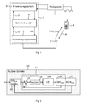
- Fig. 1 shows an overview of the entire system.
- the base station 1 is shown in its layer model.
- the base station 1 includes an application layer 2, which represents the uppermost layer and allows unimposed applications to access the layers below it.
- an application which is used to manage the base station 1 and via which the mobile terminal 9 to be located can access the application layer 2 accesses.
- the application layer 2 communicates with an underlying layer system 4.
- This layer system consists of the layers 2 and 3. This communication takes place via an interface 3.
- This interface 3 may be, for example, a Lan interface (engl. local area network).
- the layer system 4 which includes the second and the third layer, is eg in the 3GPP standard (3rd Generation Partnership Project; dt. partnership project of the third generation).
- the third layer is the Radio Resource Control Layer.
- the Radio Resource Protocol (dt radio resources protocol) is located. This ensures eg the signaling between the mobile terminal 9 (UE) and UTRAN (UMTS terrestrial radio access network). Other features of this protocol include connection setup and disconnection.
- the outer loop 20 is also implemented for power control. These will be discussed in more detail below.
- the layer system 4 which contains the second and the third layer, is connected via the interface 5 to the physical layer 1.
- This interface is preferably a Iub interface, such as this e.g. in 3GPP TS 25.435 V.5.9.0 2006-09 Release 5.
- the transmission signal is generated, transmitted to non-illustrated RF stages and emitted via the antenna 7.
- the inner loop 21 for the power control in which the control loop for the power control is executed.
- the measurement of the signal / interference ratio takes place here by each mobile terminal 9.
- the data structure of the WCDMA method which also includes UMTS, is organized in frames.
- the frame duration is eg 10 ms.
- Each frame consists eg of 15 time slots.
- a command is transmitted via the air interface 8 to the mobile terminal 9, after receiving the mobile terminal 9 either increased its transmission power by a certain value or decreased.
- the command is spoken by a TPC command (English: transmit power control).
- the mobile terminal 9 consequently adapts, for example, its transmission power 1500 times per second to a specification received from the base station 1.
- the same also applies in the opposite direction, in which the mobile terminal 9 requests the base station 1 to either increase or decrease the transmission power.
- this is not important to the present invention.
- the location of the mobile terminal 9 can be determined quickly and precisely via a bearing system 11 with the associated antenna 12.
- the bearing system 11 may optionally be connected to the base station 1 via the interface 10.
- the direction finding system 11 is preferably connected to the application layer 2.
- the direction finding system 11 informs the base station 1 that it is to restore the mobile terminal 9 to the normal state in which the field strength of the received signal of the mobile terminal 9 at the base station 1 is as high as possible should be the same as the field strength of the other connected to the base station 1 mobile terminals.
- the mobile terminal 9 may also be UMTS data cards or UMTS data sticks.
- Fig. 2 gives an overview of the interaction of the outer loop 20 and the inner loop 21, which are used to generate the TPC commands.
- the outer loop 20 is implemented in the third layer and the inner loop 21 in the first layer.
- Each base station 1 calculates the TPC command to be sent for each of the mobile terminals 9 connected to it.
- the outer control loop 20 is fed from the application layer 2 e.g. either a maximum bit error rate BER or block error rate BLER is communicated to each mobile terminal 9, or the signal / interference ratio for each individual mobile terminal 9 is determined directly by the application layer 2 established.
- the bit error rate or block error rate is applied to an input of a signal / interference ratio estimator 22.
- Another input of the estimator unit 22 is supplied with the measured bit error rate or block error rate.
- This estimation unit 22 sets a target value 28 for the signal / interference ratio and outputs it at an output again.
- the signal-to-interference ratio 28 may also be manually adjusted, e.g. between -8.2 dB and +17.3 dB. This is standard to e.g. from 3GPP TS 25.435 V5.9.0 (2006-09).
- the signal-to-interference ratio 28 is also referred to as the UL_SIR_TARGET value in the 3GPP standard. This 8-bit value sets the signal-to-interference ratio. If the value of the setpoint value reaches 28 0x00, a signal-to-interference ratio of -8.2 dB is desired. If the reference value 28 assumes the value 0xFF, a signal / interference ratio of 17.3 dB should be achieved. The gradation is 0.1 dB.
- the estimation unit 22 may in the simplest case consist of a two-point controller, which forms a difference between a maximum predetermined bit error rate or block error rate and the measured bit error rate or block error rate and, depending on whether this difference is positive or negative, the desired value 28 for the signal / Interference ratio increased or decreased by 0.1 dB.
- a direct setpoint 28 for the Signal / interference ratio is predetermined for the mobile terminal to be located 9, this setpoint value 28 for the signal / interference ratio is passed directly to the inner loop 21.
- a setpoint 28 for the signal / interference ratio of 17.3 dB does not cause the mobile terminal 9 to transmit even at the maximum transmission power.
- the setpoint value 28 for the signal / interference ratio (UL_SIR_TARGET) is subsequently transferred to the inner loop 21 and switched to a summation point 23 with a positive sign. With a negative sign, the measured value for the signal / interference ratio is switched to a second input of the summation point 23.
- the output of this summation point 23 is connected to a computing unit 24. Algorithms within the computing unit 24 determine a manipulated variable based on the difference between the signal / interference ratio set point 28 and the measured value of the signal / interference ratio.
- the manipulated variable is also referred to as a TPC command and can assume the values -1, 0 and +1, whereby in most cases only the values -1 and +1 are used.
- the arithmetic unit 24 can also be implemented as a two-point controller that outputs a +1 in the event that the difference at the summation point is greater than zero and generates a -1 in the event that the difference at the summation point 23 is less than zero. In case both sizes are equal, either a +1 or a -1 can be output.
- the manipulated variable is subsequently transmitted to the transmitting unit and receiving unit 25 and sent to the mobile terminal 9. Subsequently, the transmitting unit and receiving unit 25 receives the next data from the mobile terminal 9. The received data are then forwarded to a measuring unit 26, which determines the signal / interference ratio and turns on the summation point 23 with a negative sign. From the received data, the bit error rate or the block error rate is calculated in a second measuring unit 27. The second measuring unit 27 is implemented in the outer loop 20. The result of the second measuring unit 27 is supplied to the estimating unit 22.
- the transmission power is either increased by one dB or decreased by one dB.
- Other step sizes are optional and can also be set.
- the goal is in the known transmission power control that a maximum allowable bit error rate or block error rate is not exceeded and that the field strength of all signals of the connected to the base station 1 mobile terminals 9 at the base station 1 is as high as possible and as low as possible to a total large spatial coverage of the base station 1 to achieve.
- the outer loop 20 becomes within the third layer, for example between 10 and 100 times per second whereas the inner loop 21 is executed, for example, 1500 times per second.
- the fast transmission power control ensures that the best possible connection quality is achieved.
- Fig. 3 shows an overview of the inner loop 21 with the control unit 30 according to the invention as out Fig. 2 is known
- the inner loop 21 is fed to a setpoint 28 for the signal / interference ratio.
- This setpoint 28 for the signal / interference ratio is usually above 12.5 dB in normal operation.
- This set point 28 for the signal / interference ratio is switched to the summation point 23 with a positive sign. With a negative sign, the measured value for the signal / interference ratio is switched to the summation point 23.
- the output of the summation point 23 is connected to the arithmetic unit 24.
- the arithmetic unit 24 generates a manipulated variable, which is transmitted to the transmitting and receiving unit 25 and sent to the mobile terminal 9.
- the transmitting and receiving unit 25 furthermore receives a signal from the mobile terminal 9 and forwards it to the first measuring unit 26. This measures the signal / interference ratio and returns this to the summation point 23.
- a control unit 31 is in Fig. 3 dotted marked. This comprises the summation point 23 and the arithmetic unit 24.
- the control unit 31 is supplied to a first input 32, a desired value 28 for the signal / interference ratio.
- a second input 33 of the control unit 31 is connected to the measuring unit 26.
- At an output 34 of the control unit 31 is a manipulated variable ready, which is transmitted via the transmitting and receiving unit 25 to the mobile terminal 9.
- the layer system 4 consisting of the layers 2 and 3, it must be changed as little as the interfaces 3 and 5, which connect the individual layers together. This ensures that the base station 1 corresponds to a large extent the 3GPP standard and reduce the necessary changes to a minimum.
- the inner loop 21 according to the invention has a control unit 30, which is supplied at a first input of the setpoint value 28 to be set for the signal / interference ratio. Once the inner loop 21, a set value 28 is supplied, which is not set in the normal operation, this is detected by the control unit 30. Preferably, the control unit 30 is set to respond to the minimum signal / interference ratio set point 28 to be set.
- this value is set by the user in the application layer 2 for the mobile terminal 9 to be located, it is supplied to the inner loop 21 for the power control of the mobile terminal 9 to be located.
- the control unit 30 detects this And performs different actions depending on the inner loop 21 embodiment.
- FIG. 3 Three different embodiments are shown how the inner loop 21 is easily changed to permanently generate commands to increase the transmission power of the mobile terminal 9.
- the individual elements are interconnected as in Fig. 3 is shown.
- the control unit 30 is connected to a first switching unit 35.
- the first switching unit 35 has two inputs, which are alternately switched to an output depending on the switching state.
- the first input of the first switching unit 35 the set value 28 of the signal / interference ratio is supplied.
- the second input of the first switching unit 35 is connected to a memory unit 38.
- the first switching unit 35 then changes the switch position and connects in the following the second input to the output.
- the memory unit 38 is connected to the summation point 23 via the first input 32 of the control unit 31.
- the new setpoint for the signal / interference ratio, which is loaded from the memory unit 38, is chosen so that this is always greater than the measured by the measuring unit 26 setpoint for the signal / interference ratio.
- the control unit 31 then generates always a manipulated variable (a TPC command), the the mobile terminal 9 requests to further increase the transmission power.
- control unit 30 is connected to a second switching unit 36.
- the second switching unit 36 has two inputs, which are alternately switched to an output depending on the switching state.
- the first input of the second switching unit 35 is supplied with the measured value of the signal / interference ratio from the measuring unit 26.
- the second input of the second switching unit 36 is connected to a memory unit 38.
- the second switching unit 36 then changes the switch position and connects in the following the second input to the output.
- the memory unit 38 is connected to the summation point 23.
- the new value for the measured signal / interference ratio, which is loaded from the memory unit 38, is there chosen so that it is always smaller than the setpoint value 28 for the signal / interference ratio, which is applied to the first input 32 of the control unit 31.
- the control unit 31 then always generates a manipulated variable that prompts the mobile terminal 9 to further increase the transmission power.
- control unit 30 is connected to a third switching unit 37.
- the third switching unit 37 has two inputs, which are alternately switched to an output depending on the switching state.
- the first input of the third switching unit 37 is connected to the output 34 of Control unit 31 connected, about which this is supplied to the manipulated variable.
- the second input of the third switching unit 37 is connected to the memory unit 38.
- the third switching unit 37 then changes the switch position and connects in the following the second input to the output.
- the memory unit 38 is connected to the transmitting and receiving unit 25.
- the manipulated variable for the transmission power of the mobile terminal 9 to be located is taken from the memory unit 38 below.
- the new value for the manipulated variable, which is loaded from the memory unit 38 is chosen such that it always causes the mobile terminal 9 to carry the Transmission power always further increased. Since the manipulated variable is TPC commands which can only assume the values -1, 0, +1, preferably -1 and +1, a +1 is always loaded from the memory unit 38. In the case of the manipulated variable loaded from the memory unit 38, it is therefore also possible to speak of a manipulated manipulated variable because it is independent of the control unit 31.
- control unit 30 is indirectly connected to the control unit 31 via the switching units 35, 36 or 37.
- control unit 30 may also be connected directly to the control unit 31.
- the control unit 30 causes in a direct connection that algorithms are changed in the arithmetic unit 24 such that a control variable is generated by the control unit 31, which causes the mobile terminal 9 to further increase the transmission power.
- Both in the direct, as well as in the indirect connection between the control unit 30 and the Control unit 31 is a causal connection because a change in an output of the control unit 30 causes a change in the manipulated variable of the control unit 31.
- a normal set point 28 for the signal / interference ratio (> 12.5 dB) of the meanwhile located mobile terminal 9 is transmitted to the inner loop 21.
- the control unit 28 recognizes this and controls the switching units 35 or 36 or 37 as in FIG Fig. 3 shown on.
- Fig. 4 shows a further overview of the inner loop 21 with the control unit according to the invention 30.
- the structure of the inner loop 21 from Fig. 4 is essentially the same as Fig. 3 to which reference is hereby made.
- Only the control unit 30 is no longer supplied to the setpoint 28 for the signal / interference ratio at an input, but a separate command.
- the control unit 30 is in Fig. 4 via another interface 40, such as Ethernet connected to the application layer 2. Via this interface 40, the command to increase the lowering of the transmission power of the mobile terminal to be located 9 to the inner loop 21, which is located in the physical layer 6, sent.
- Other interfaces familiar to the person skilled in the art are likewise conceivable for this purpose.
- Fig. 5 shows a flowchart which describes the inventive procedure for increasing the transmission power of a mobile terminal 9.
- a first step S 1 the selection of the mobile terminal 9 to be located takes place.
- a user enters, for example, the IMEI number of the mobile terminal 9 to be located in a program which communicates with the application layer 2.
- an instruction for increasing the transmission power is transmitted from the application layer 2 to the physical layer 6.
- the command is preferably the command for setting the signal / interference ratio for a mobile terminal 9.
- This command is changed to send a value to the physical layer 6 for the signal / interference ratio which is normal Operation does not occur.
- the bit sequence 0x00 for the UL_SIR_TARGET value is particularly preferably transmitted.
- the advantage here is that the layer system 4, comprising layers 2 and 3, does not have to be changed.
- the already existing interfaces eg Iub interface
- which connect these layers with each other also do not need to be adapted.
- a manipulated variable (TPC command) is generated by a control unit 31 within the inner loop 21 and transmitted via the transmitting and receiving unit 25 to the mobile terminal 9, which causes the mobile terminal 9, the transmission power accordingly to increase the 3GPP standard (Table 6.4 in 3GPP TS 25.101 V5.20.0 (2006-12) Release 5).
- a control unit 30 checks whether the received command includes a specific bit sequence. If this is the case, according to the description FIG. 3 and FIG. 4 modifies the manipulated variable and transmitted to the mobile terminal 9. In the event that the mobile terminal 9 at this time maintains no data or voice connection to the base station 1, according to the patent EP 1 199 903 B1 one or more silent call connections are established to the mobile terminal.
- a fourth step S 4 the direction finding system 10 attempts to locate the mobile terminal 9. Because a positioning operation takes several seconds, the third step S 3 is executed several times, so that the transmission power of the mobile terminal 9 increases incrementally.
- the application layer 2 transmits a signal / interference ratio to the inner loop 21 or a bit error rate to the outer loop 20, where the bit sequence for the signal / interference ratio 28 does not cause the control loop 31 is manipulated by the control unit 30 such that the manipulated variable generated causes the mobile terminal 9 to continue to increase the transmission power further up to the maximum transmission power.
- a maximum permissible bit error rate or block error rate is preferably transmitted to the outer loop 20, which is identical to the maximum permissible bit error rate or block error rate of the other mobile terminals connected to the base station.
- a signal / interference ratio can also be specified, which is preferably more than 12.5 dB.
- the invention is not limited to the illustrated embodiments. All described and / or drawn elements can be combined with one another in the context of the invention as desired.
- the invention is not only usable for UMTS-enabled mobile terminals. Rather, all mobile devices whose radio technology is based on WCDMA, be brought with the aid of the present invention to increase their transmission power up to the maximum transmission power.
- the device according to the invention and the method according to the invention are preferably used within a computer system or within an FPGA (Field Programmable Gate array; dt. Arrangement with programmable logic gates) used.
Landscapes
- Engineering & Computer Science (AREA)
- Computer Networks & Wireless Communication (AREA)
- Signal Processing (AREA)
- Quality & Reliability (AREA)
- Mobile Radio Communication Systems (AREA)
Applications Claiming Priority (1)
| Application Number | Priority Date | Filing Date | Title |
|---|---|---|---|
| DE102010012814A DE102010012814A1 (de) | 2010-03-26 | 2010-03-26 | Vorrichtung und Verfahren zur Erfassung von mobilen Endgeräten |
Publications (3)
| Publication Number | Publication Date |
|---|---|
| EP2369877A2 true EP2369877A2 (fr) | 2011-09-28 |
| EP2369877A3 EP2369877A3 (fr) | 2012-07-18 |
| EP2369877B1 EP2369877B1 (fr) | 2015-10-21 |
Family
ID=43742467
Family Applications (1)
| Application Number | Title | Priority Date | Filing Date |
|---|---|---|---|
| EP11156835.8A Active EP2369877B1 (fr) | 2010-03-26 | 2011-03-03 | Appareil et procédé pour détection d'un terminal mobile |
Country Status (2)
| Country | Link |
|---|---|
| EP (1) | EP2369877B1 (fr) |
| DE (2) | DE102010012814A1 (fr) |
Citations (2)
| Publication number | Priority date | Publication date | Assignee | Title |
|---|---|---|---|---|
| EP1119903B1 (fr) | 1998-09-30 | 2002-05-29 | Infineon Technologies AG | Circuiterie pour melanger un signal d'entree et un signal d'oscillateur |
| EP1199903B1 (fr) | 2000-10-16 | 2005-06-01 | Rohde & Schwarz GmbH & Co. KG | Procédé d'activation d'un téléphone mobile sans intervention de l'utilisateur |
Family Cites Families (4)
| Publication number | Priority date | Publication date | Assignee | Title |
|---|---|---|---|---|
| FI86352C (fi) * | 1989-11-14 | 1992-08-10 | Nokia Oy Ab | Digitaliskt radiolaenksystem och foerfarande foer reglering av en saendingseffekt i ett digitaliskt radiolaenksystem. |
| WO1997008847A1 (fr) * | 1995-08-31 | 1997-03-06 | Nokia Telecommunications Oy | Procede de regulation de la puissance d'emission d'un emetteur radio dans un systeme de communication cellulaire |
| US6560462B1 (en) * | 2000-03-07 | 2003-05-06 | Samsung Electronics Co., Ltd. | System and method for determining the location of a mobile station in a wireless network |
| GB0506082D0 (en) * | 2005-03-24 | 2005-05-04 | Koninkl Philips Electronics Nv | Communication system, apparatus, and method of operating a communication system |
-
2010
- 2010-03-26 DE DE102010012814A patent/DE102010012814A1/de not_active Withdrawn
-
2011
- 2011-03-03 EP EP11156835.8A patent/EP2369877B1/fr active Active
- 2011-03-03 DE DE201120110130 patent/DE202011110130U1/de not_active Expired - Lifetime
Patent Citations (2)
| Publication number | Priority date | Publication date | Assignee | Title |
|---|---|---|---|---|
| EP1119903B1 (fr) | 1998-09-30 | 2002-05-29 | Infineon Technologies AG | Circuiterie pour melanger un signal d'entree et un signal d'oscillateur |
| EP1199903B1 (fr) | 2000-10-16 | 2005-06-01 | Rohde & Schwarz GmbH & Co. KG | Procédé d'activation d'un téléphone mobile sans intervention de l'utilisateur |
Also Published As
| Publication number | Publication date |
|---|---|
| DE102010012814A1 (de) | 2011-09-29 |
| EP2369877A3 (fr) | 2012-07-18 |
| EP2369877B1 (fr) | 2015-10-21 |
| DE202011110130U1 (de) | 2012-11-28 |
Similar Documents
| Publication | Publication Date | Title |
|---|---|---|
| DE69625009T2 (de) | Verfahren zur Steuerung der Sendeleistung eines Funksenders | |
| DE60123217T2 (de) | Anwenderausrüstung und vorgehensweise zur handhabung von synchronisationslosen zustanden | |
| DE60211234T2 (de) | Zelluläres System, Basistation, Mobilstation und Kommunikationssteuerungsverfahren dafür | |
| DE69913232T3 (de) | Verfahren und System zur Sendeleistungsregelung während Makrodiversität | |
| DE69901633T2 (de) | Vorrichtung und Verfahren zur Steuerung der Sendeleistung und Funkkommunikationssystem und Funkkommunikationsverfahren | |
| DE69714635T2 (de) | Leistungsregelung in einer zellularen Kommunikationsanordnung | |
| DE60127138T2 (de) | Regelung der Sendeleistung in einem CDMA-basierten System | |
| DE69904711T2 (de) | Verfahren und vorrichtung zur leistungssteuerung in einem mobilen telekommunikationssystem | |
| DE60132848T2 (de) | Verfahren zur Sendeleistungssteuerung in einem Mobilfunkkommunikationssystem | |
| DE20318137U1 (de) | Drahtlose Sende-/Empfangs-Einheit | |
| DE602005000379T2 (de) | Verfahren und Anordnung zur Sendeleistungsregelung in einem drahtlosen Netzwerk | |
| DE10017930A1 (de) | Verfahren zur Sendeleistungsregelung in einem Funk-SIGMAommunikationssystem | |
| DE60035703T2 (de) | Verfahren und anordnung zur regelung der sendeleistung und ein netzwerkelement | |
| WO2004100393A2 (fr) | Procede pour commander la puissance d'emission d'une station emettrice d'un systeme de radiocommunication, station emettrice, station receptrice et systeme de radiocommunication | |
| DE102014102677A1 (de) | Mobil-endgerät und verfahren zum bestimmen eines empfangsfensters | |
| EP1864397B1 (fr) | Procede pour mettre a l'echelle un canal e-dch | |
| EP1079542A1 (fr) | Contrôle de la puissance d'émission dans un système de communication mobile | |
| EP2369877B1 (fr) | Appareil et procédé pour détection d'un terminal mobile | |
| EP1290813B1 (fr) | Procede pour reguler la puissance d'emission d'une station d'emission, et station d'emission | |
| DE69937061T2 (de) | Gerät und verfahren zur leistungsregelung eines kommunikationsgerätes | |
| WO2004032550A1 (fr) | Adaptation de la communication entre une station mobile et une premiere station de base sur la base d'une evaluation de la perturbation se produisant dans une deuxieme station mobile et causee par le signal de ladite station mobile | |
| DE102009015090A1 (de) | Einrichtung und Verfahren zur Steuerung eines Leistungsverstärkers einer Mobilfunksendeeinrichtung | |
| EP1741249B1 (fr) | Procédé, station d'abonné et dispositif de réseau pour la communication radio, en particulier dans le contexte de services HSDPA | |
| DE10323191B4 (de) | Verfahren zum Betrieb eines Mobilfunksystems, Mobilfunksystem und Basisstation | |
| DE102024201227A1 (de) | System und einrichtung zum initialisieren eines algorithmus und damit in verbindung stehendes verfahren |
Legal Events
| Date | Code | Title | Description |
|---|---|---|---|
| REG | Reference to a national code |
Ref country code: DE Ref legal event code: R138 Ref document number: 502011008141 Country of ref document: DE Free format text: GERMAN DOCUMENT NUMBER IS 502011008141 Ref country code: DE Ref legal event code: R138 Ref document number: 202011110130 Country of ref document: DE Free format text: GERMAN DOCUMENT NUMBER IS 502011008141 |
|
| PUAI | Public reference made under article 153(3) epc to a published international application that has entered the european phase |
Free format text: ORIGINAL CODE: 0009012 |
|
| AK | Designated contracting states |
Kind code of ref document: A2 Designated state(s): AL AT BE BG CH CY CZ DE DK EE ES FI FR GB GR HR HU IE IS IT LI LT LU LV MC MK MT NL NO PL PT RO RS SE SI SK SM TR |
|
| AX | Request for extension of the european patent |
Extension state: BA ME |
|
| PUAL | Search report despatched |
Free format text: ORIGINAL CODE: 0009013 |
|
| AK | Designated contracting states |
Kind code of ref document: A3 Designated state(s): AL AT BE BG CH CY CZ DE DK EE ES FI FR GB GR HR HU IE IS IT LI LT LU LV MC MK MT NL NO PL PT RO RS SE SI SK SM TR |
|
| AX | Request for extension of the european patent |
Extension state: BA ME |
|
| RIC1 | Information provided on ipc code assigned before grant |
Ipc: H04W 52/24 20090101ALI20120614BHEP Ipc: H04W 52/28 20090101ALI20120614BHEP Ipc: H04W 52/36 20090101ALI20120614BHEP Ipc: H04W 52/10 20090101AFI20120614BHEP Ipc: H04W 52/14 20090101ALI20120614BHEP |
|
| 17P | Request for examination filed |
Effective date: 20130118 |
|
| 17Q | First examination report despatched |
Effective date: 20130318 |
|
| REG | Reference to a national code |
Ref country code: DE Ref legal event code: R079 Ref document number: 502011008141 Country of ref document: DE Free format text: PREVIOUS MAIN CLASS: H04W0052100000 Ipc: H04W0052380000 |
|
| RIC1 | Information provided on ipc code assigned before grant |
Ipc: H04W 52/14 20090101ALI20150422BHEP Ipc: H04W 52/10 20090101ALI20150422BHEP Ipc: H04W 52/38 20090101AFI20150422BHEP Ipc: H04W 52/36 20090101ALI20150422BHEP Ipc: H04W 52/28 20090101ALI20150422BHEP Ipc: H04W 52/24 20090101ALI20150422BHEP |
|
| GRAP | Despatch of communication of intention to grant a patent |
Free format text: ORIGINAL CODE: EPIDOSNIGR1 |
|
| INTG | Intention to grant announced |
Effective date: 20150610 |
|
| GRAS | Grant fee paid |
Free format text: ORIGINAL CODE: EPIDOSNIGR3 |
|
| GRAA | (expected) grant |
Free format text: ORIGINAL CODE: 0009210 |
|
| AK | Designated contracting states |
Kind code of ref document: B1 Designated state(s): AL AT BE BG CH CY CZ DE DK EE ES FI FR GB GR HR HU IE IS IT LI LT LU LV MC MK MT NL NO PL PT RO RS SE SI SK SM TR |
|
| REG | Reference to a national code |
Ref country code: GB Ref legal event code: FG4D Free format text: NOT ENGLISH Ref country code: NL Ref legal event code: MP Effective date: 20151021 |
|
| REG | Reference to a national code |
Ref country code: CH Ref legal event code: EP |
|
| REG | Reference to a national code |
Ref country code: AT Ref legal event code: REF Ref document number: 757361 Country of ref document: AT Kind code of ref document: T Effective date: 20151115 |
|
| REG | Reference to a national code |
Ref country code: IE Ref legal event code: FG4D Free format text: LANGUAGE OF EP DOCUMENT: GERMAN |
|
| REG | Reference to a national code |
Ref country code: DE Ref legal event code: R096 Ref document number: 502011008141 Country of ref document: DE |
|
| REG | Reference to a national code |
Ref country code: FR Ref legal event code: PLFP Year of fee payment: 6 |
|
| REG | Reference to a national code |
Ref country code: LT Ref legal event code: MG4D |
|
| PG25 | Lapsed in a contracting state [announced via postgrant information from national office to epo] |
Ref country code: IS Free format text: LAPSE BECAUSE OF FAILURE TO SUBMIT A TRANSLATION OF THE DESCRIPTION OR TO PAY THE FEE WITHIN THE PRESCRIBED TIME-LIMIT Effective date: 20160221 Ref country code: ES Free format text: LAPSE BECAUSE OF FAILURE TO SUBMIT A TRANSLATION OF THE DESCRIPTION OR TO PAY THE FEE WITHIN THE PRESCRIBED TIME-LIMIT Effective date: 20151021 Ref country code: HR Free format text: LAPSE BECAUSE OF FAILURE TO SUBMIT A TRANSLATION OF THE DESCRIPTION OR TO PAY THE FEE WITHIN THE PRESCRIBED TIME-LIMIT Effective date: 20151021 Ref country code: NO Free format text: LAPSE BECAUSE OF FAILURE TO SUBMIT A TRANSLATION OF THE DESCRIPTION OR TO PAY THE FEE WITHIN THE PRESCRIBED TIME-LIMIT Effective date: 20160121 Ref country code: NL Free format text: LAPSE BECAUSE OF FAILURE TO SUBMIT A TRANSLATION OF THE DESCRIPTION OR TO PAY THE FEE WITHIN THE PRESCRIBED TIME-LIMIT Effective date: 20151021 Ref country code: LT Free format text: LAPSE BECAUSE OF FAILURE TO SUBMIT A TRANSLATION OF THE DESCRIPTION OR TO PAY THE FEE WITHIN THE PRESCRIBED TIME-LIMIT Effective date: 20151021 |
|
| PG25 | Lapsed in a contracting state [announced via postgrant information from national office to epo] |
Ref country code: PT Free format text: LAPSE BECAUSE OF FAILURE TO SUBMIT A TRANSLATION OF THE DESCRIPTION OR TO PAY THE FEE WITHIN THE PRESCRIBED TIME-LIMIT Effective date: 20160222 Ref country code: RS Free format text: LAPSE BECAUSE OF FAILURE TO SUBMIT A TRANSLATION OF THE DESCRIPTION OR TO PAY THE FEE WITHIN THE PRESCRIBED TIME-LIMIT Effective date: 20151021 Ref country code: GR Free format text: LAPSE BECAUSE OF FAILURE TO SUBMIT A TRANSLATION OF THE DESCRIPTION OR TO PAY THE FEE WITHIN THE PRESCRIBED TIME-LIMIT Effective date: 20160122 Ref country code: PL Free format text: LAPSE BECAUSE OF FAILURE TO SUBMIT A TRANSLATION OF THE DESCRIPTION OR TO PAY THE FEE WITHIN THE PRESCRIBED TIME-LIMIT Effective date: 20151021 Ref country code: FI Free format text: LAPSE BECAUSE OF FAILURE TO SUBMIT A TRANSLATION OF THE DESCRIPTION OR TO PAY THE FEE WITHIN THE PRESCRIBED TIME-LIMIT Effective date: 20151021 Ref country code: LV Free format text: LAPSE BECAUSE OF FAILURE TO SUBMIT A TRANSLATION OF THE DESCRIPTION OR TO PAY THE FEE WITHIN THE PRESCRIBED TIME-LIMIT Effective date: 20151021 Ref country code: SE Free format text: LAPSE BECAUSE OF FAILURE TO SUBMIT A TRANSLATION OF THE DESCRIPTION OR TO PAY THE FEE WITHIN THE PRESCRIBED TIME-LIMIT Effective date: 20151021 |
|
| REG | Reference to a national code |
Ref country code: DE Ref legal event code: R097 Ref document number: 502011008141 Country of ref document: DE |
|
| PG25 | Lapsed in a contracting state [announced via postgrant information from national office to epo] |
Ref country code: CZ Free format text: LAPSE BECAUSE OF FAILURE TO SUBMIT A TRANSLATION OF THE DESCRIPTION OR TO PAY THE FEE WITHIN THE PRESCRIBED TIME-LIMIT Effective date: 20151021 |
|
| PLBE | No opposition filed within time limit |
Free format text: ORIGINAL CODE: 0009261 |
|
| STAA | Information on the status of an ep patent application or granted ep patent |
Free format text: STATUS: NO OPPOSITION FILED WITHIN TIME LIMIT |
|
| PG25 | Lapsed in a contracting state [announced via postgrant information from national office to epo] |
Ref country code: EE Free format text: LAPSE BECAUSE OF FAILURE TO SUBMIT A TRANSLATION OF THE DESCRIPTION OR TO PAY THE FEE WITHIN THE PRESCRIBED TIME-LIMIT Effective date: 20151021 Ref country code: SK Free format text: LAPSE BECAUSE OF FAILURE TO SUBMIT A TRANSLATION OF THE DESCRIPTION OR TO PAY THE FEE WITHIN THE PRESCRIBED TIME-LIMIT Effective date: 20151021 Ref country code: RO Free format text: LAPSE BECAUSE OF FAILURE TO SUBMIT A TRANSLATION OF THE DESCRIPTION OR TO PAY THE FEE WITHIN THE PRESCRIBED TIME-LIMIT Effective date: 20151021 Ref country code: SM Free format text: LAPSE BECAUSE OF FAILURE TO SUBMIT A TRANSLATION OF THE DESCRIPTION OR TO PAY THE FEE WITHIN THE PRESCRIBED TIME-LIMIT Effective date: 20151021 Ref country code: BE Free format text: LAPSE BECAUSE OF NON-PAYMENT OF DUE FEES Effective date: 20160331 Ref country code: DK Free format text: LAPSE BECAUSE OF FAILURE TO SUBMIT A TRANSLATION OF THE DESCRIPTION OR TO PAY THE FEE WITHIN THE PRESCRIBED TIME-LIMIT Effective date: 20151021 |
|
| 26N | No opposition filed |
Effective date: 20160722 |
|
| PG25 | Lapsed in a contracting state [announced via postgrant information from national office to epo] |
Ref country code: LU Free format text: LAPSE BECAUSE OF FAILURE TO SUBMIT A TRANSLATION OF THE DESCRIPTION OR TO PAY THE FEE WITHIN THE PRESCRIBED TIME-LIMIT Effective date: 20160303 Ref country code: MC Free format text: LAPSE BECAUSE OF FAILURE TO SUBMIT A TRANSLATION OF THE DESCRIPTION OR TO PAY THE FEE WITHIN THE PRESCRIBED TIME-LIMIT Effective date: 20151021 |
|
| REG | Reference to a national code |
Ref country code: CH Ref legal event code: PL |
|
| PG25 | Lapsed in a contracting state [announced via postgrant information from national office to epo] |
Ref country code: SI Free format text: LAPSE BECAUSE OF FAILURE TO SUBMIT A TRANSLATION OF THE DESCRIPTION OR TO PAY THE FEE WITHIN THE PRESCRIBED TIME-LIMIT Effective date: 20151021 |
|
| REG | Reference to a national code |
Ref country code: IE Ref legal event code: MM4A |
|
| PG25 | Lapsed in a contracting state [announced via postgrant information from national office to epo] |
Ref country code: CH Free format text: LAPSE BECAUSE OF NON-PAYMENT OF DUE FEES Effective date: 20160331 Ref country code: LI Free format text: LAPSE BECAUSE OF NON-PAYMENT OF DUE FEES Effective date: 20160331 Ref country code: IE Free format text: LAPSE BECAUSE OF NON-PAYMENT OF DUE FEES Effective date: 20160303 |
|
| REG | Reference to a national code |
Ref country code: FR Ref legal event code: PLFP Year of fee payment: 7 |
|
| REG | Reference to a national code |
Ref country code: AT Ref legal event code: MM01 Ref document number: 757361 Country of ref document: AT Kind code of ref document: T Effective date: 20160303 |
|
| PG25 | Lapsed in a contracting state [announced via postgrant information from national office to epo] |
Ref country code: AT Free format text: LAPSE BECAUSE OF NON-PAYMENT OF DUE FEES Effective date: 20160303 Ref country code: MT Free format text: LAPSE BECAUSE OF FAILURE TO SUBMIT A TRANSLATION OF THE DESCRIPTION OR TO PAY THE FEE WITHIN THE PRESCRIBED TIME-LIMIT Effective date: 20151021 |
|
| REG | Reference to a national code |
Ref country code: FR Ref legal event code: PLFP Year of fee payment: 8 |
|
| PG25 | Lapsed in a contracting state [announced via postgrant information from national office to epo] |
Ref country code: HU Free format text: LAPSE BECAUSE OF FAILURE TO SUBMIT A TRANSLATION OF THE DESCRIPTION OR TO PAY THE FEE WITHIN THE PRESCRIBED TIME-LIMIT; INVALID AB INITIO Effective date: 20110303 Ref country code: CY Free format text: LAPSE BECAUSE OF FAILURE TO SUBMIT A TRANSLATION OF THE DESCRIPTION OR TO PAY THE FEE WITHIN THE PRESCRIBED TIME-LIMIT Effective date: 20151021 |
|
| PG25 | Lapsed in a contracting state [announced via postgrant information from national office to epo] |
Ref country code: TR Free format text: LAPSE BECAUSE OF FAILURE TO SUBMIT A TRANSLATION OF THE DESCRIPTION OR TO PAY THE FEE WITHIN THE PRESCRIBED TIME-LIMIT Effective date: 20151021 Ref country code: MK Free format text: LAPSE BECAUSE OF FAILURE TO SUBMIT A TRANSLATION OF THE DESCRIPTION OR TO PAY THE FEE WITHIN THE PRESCRIBED TIME-LIMIT Effective date: 20151021 |
|
| PG25 | Lapsed in a contracting state [announced via postgrant information from national office to epo] |
Ref country code: BG Free format text: LAPSE BECAUSE OF FAILURE TO SUBMIT A TRANSLATION OF THE DESCRIPTION OR TO PAY THE FEE WITHIN THE PRESCRIBED TIME-LIMIT Effective date: 20151021 |
|
| PG25 | Lapsed in a contracting state [announced via postgrant information from national office to epo] |
Ref country code: AL Free format text: LAPSE BECAUSE OF FAILURE TO SUBMIT A TRANSLATION OF THE DESCRIPTION OR TO PAY THE FEE WITHIN THE PRESCRIBED TIME-LIMIT Effective date: 20151021 |
|
| P01 | Opt-out of the competence of the unified patent court (upc) registered |
Effective date: 20230525 |
|
| PGFP | Annual fee paid to national office [announced via postgrant information from national office to epo] |
Ref country code: IT Payment date: 20250331 Year of fee payment: 15 |
|
| PGFP | Annual fee paid to national office [announced via postgrant information from national office to epo] |
Ref country code: GB Payment date: 20260324 Year of fee payment: 16 |
|
| PGFP | Annual fee paid to national office [announced via postgrant information from national office to epo] |
Ref country code: DE Payment date: 20260320 Year of fee payment: 16 |
|
| PGFP | Annual fee paid to national office [announced via postgrant information from national office to epo] |
Ref country code: FR Payment date: 20260325 Year of fee payment: 16 |