EP2369996B1 - 3d-mammografie - Google Patents
3d-mammografie Download PDFInfo
- Publication number
- EP2369996B1 EP2369996B1 EP09828703.0A EP09828703A EP2369996B1 EP 2369996 B1 EP2369996 B1 EP 2369996B1 EP 09828703 A EP09828703 A EP 09828703A EP 2369996 B1 EP2369996 B1 EP 2369996B1
- Authority
- EP
- European Patent Office
- Prior art keywords
- ray source
- locking means
- breast
- during
- movement
- Prior art date
- Legal status (The legal status is an assumption and is not a legal conclusion. Google has not performed a legal analysis and makes no representation as to the accuracy of the status listed.)
- Not-in-force
Links
Images


Classifications
-
- A—HUMAN NECESSITIES
- A61—MEDICAL OR VETERINARY SCIENCE; HYGIENE
- A61B—DIAGNOSIS; SURGERY; IDENTIFICATION
- A61B6/00—Apparatus or devices for radiation diagnosis; Apparatus or devices for radiation diagnosis combined with radiation therapy equipment
- A61B6/02—Arrangements for diagnosis sequentially in different planes; Stereoscopic radiation diagnosis
- A61B6/022—Stereoscopic imaging
-
- A—HUMAN NECESSITIES
- A61—MEDICAL OR VETERINARY SCIENCE; HYGIENE
- A61B—DIAGNOSIS; SURGERY; IDENTIFICATION
- A61B6/00—Apparatus or devices for radiation diagnosis; Apparatus or devices for radiation diagnosis combined with radiation therapy equipment
- A61B6/04—Positioning of patients; Tiltable beds or the like
- A61B6/0487—Motor-assisted positioning
-
- A—HUMAN NECESSITIES
- A61—MEDICAL OR VETERINARY SCIENCE; HYGIENE
- A61B—DIAGNOSIS; SURGERY; IDENTIFICATION
- A61B6/00—Apparatus or devices for radiation diagnosis; Apparatus or devices for radiation diagnosis combined with radiation therapy equipment
-
- A—HUMAN NECESSITIES
- A61—MEDICAL OR VETERINARY SCIENCE; HYGIENE
- A61B—DIAGNOSIS; SURGERY; IDENTIFICATION
- A61B6/00—Apparatus or devices for radiation diagnosis; Apparatus or devices for radiation diagnosis combined with radiation therapy equipment
- A61B6/04—Positioning of patients; Tiltable beds or the like
-
- A—HUMAN NECESSITIES
- A61—MEDICAL OR VETERINARY SCIENCE; HYGIENE
- A61B—DIAGNOSIS; SURGERY; IDENTIFICATION
- A61B6/00—Apparatus or devices for radiation diagnosis; Apparatus or devices for radiation diagnosis combined with radiation therapy equipment
- A61B6/02—Arrangements for diagnosis sequentially in different planes; Stereoscopic radiation diagnosis
- A61B6/03—Computed tomography [CT]
-
- A—HUMAN NECESSITIES
- A61—MEDICAL OR VETERINARY SCIENCE; HYGIENE
- A61B—DIAGNOSIS; SURGERY; IDENTIFICATION
- A61B6/00—Apparatus or devices for radiation diagnosis; Apparatus or devices for radiation diagnosis combined with radiation therapy equipment
- A61B6/44—Constructional features of apparatus for radiation diagnosis
- A61B6/4476—Constructional features of apparatus for radiation diagnosis related to motor-assisted motion of the source unit
-
- A—HUMAN NECESSITIES
- A61—MEDICAL OR VETERINARY SCIENCE; HYGIENE
- A61B—DIAGNOSIS; SURGERY; IDENTIFICATION
- A61B6/00—Apparatus or devices for radiation diagnosis; Apparatus or devices for radiation diagnosis combined with radiation therapy equipment
- A61B6/50—Apparatus or devices for radiation diagnosis; Apparatus or devices for radiation diagnosis combined with radiation therapy equipment specially adapted for specific body parts; specially adapted for specific clinical applications
- A61B6/502—Apparatus or devices for radiation diagnosis; Apparatus or devices for radiation diagnosis combined with radiation therapy equipment specially adapted for specific body parts; specially adapted for specific clinical applications for diagnosis of breast, i.e. mammography
-
- A—HUMAN NECESSITIES
- A61—MEDICAL OR VETERINARY SCIENCE; HYGIENE
- A61B—DIAGNOSIS; SURGERY; IDENTIFICATION
- A61B6/00—Apparatus or devices for radiation diagnosis; Apparatus or devices for radiation diagnosis combined with radiation therapy equipment
- A61B6/04—Positioning of patients; Tiltable beds or the like
- A61B6/0407—Supports, e.g. tables or beds, for the body or parts of the body
- A61B6/0414—Supports, e.g. tables or beds, for the body or parts of the body with compression means
Definitions
- the present invention relates to 3D mammography, in which individual images of a breast are taken at different projection angles, typically within an angle of about +/- 30 degrees from the vertical, and in which a 3D image is subsequently synthesized from this image information by an applicable image processing software.
- Breast cancer is the most common type of cancer in women. According to investigations, about one in every ten women contract breast cancer at some point in their lives. When breast cancer is detected on the basis of symptoms, the illness often has already developed to a stage where the prognosis for recovery is relatively poor. Some of the cases are detected in screening programs arranged in many countries for women over the age of 40. Screening often reveals a cancer at a very early stage, so its treatment can be started in time and recovery is thus more likely.
- Mammography is a widely used method in breast cancer screening as a clinical investigation method and also in follow-up diagnosis.
- Mammography is an X-ray imaging method wherein an apparatus specifically designed for this purpose is used.
- screening studies mammography has been reported to have a sensitivity of 90 - 93 % and a specificity of 90 - 97 %. This indicates that screening studies are useful and that early detection of breast cancer by screening can save human lives. It has been established that mammography reduces breast cancer mortality by 35 percent among women over 50 and by 25 - 35 percent among women at the age of 40 - 50 years.
- the mammography images are examined to detect various anomalies in the breast, such as calcifications, i.e. small deposits of calcium in the soft breast tissue.
- a calcification generally cannot be detected by feeling the breast, but it is visible in the x-ray image.
- Large calcifications are generally not associated with cancer, but clusters of small calcium deposits, i.e. so-called micro-calcifications, are an indication of extra breast cell activity, which may be associated with breast cancer.
- Other features to be detected by mammography include cysts and fi-broadenomas, which, however, are generally not associated with cancer.
- the breast gland is compressed between two compression plates and exposed to radiation at least twice, from above and from an oblique direction. If necessary, additionally a third image is taken squarely from the side.
- the tissue layers lie on top of each other in the direction of the x-ray beam, these irradiations produce two-dimensional images in which strongly absorbing structures may hinder the detection of structures lying beneath them.
- a typical digital mammography apparatus comprises a frame part and a C-arm or a corresponding structure rotatably connected to the frame part. At the first end of the C-arm, there is arranged an x-ray source and at the second end, a radiation detector. A term imaging means is often used for these devices. Disposed substantially in the region between said x-ray source and detector, typically at close proximity to the detector, compression plates are arranged which are designed for positioning the breast as compressed for the duration of the exposure.
- US patent application publication 2004/0101096 A1 discloses a mammography apparatus wherein the compression plates are either shifted as the x-ray source is rotated, or the compression plates are tilted while the x-ray source is kept stationary.
- the x-ray source located at the (upper) end of the C-arm, is a relatively heavy component. In the case of step-by-step movement of the x-ray source, prior to each exposure the imaging apparatus should have reached a vibration free status.
- the structures of the mammography apparatus should be optimized in view of the number of accelerations, decelerations and stops (stabilization times) comprised in the multi-phase imaging procedure. The overall time needed for an imaging procedure like this tends to become quite long.
- the object of the current invention is focused on eliminating or reducing at least some of the problems of the imaging systems discussed above.
- the object of the invention is reached by the method and apparatus of the independent claims 1 and 10 attached hereto. Some preferable embodiments of the invention are presented in the attached dependent claims.
- the invention makes 3D mammography possible with the existing type of mammography apparatus, i.e. with the same kind of x-ray sources and C-arm and related construction as are typically used, by enabling the use of substantially long exposure times even though continuously moving the x-ray source during the imaging procedure. This is made possible by arranging for the breast to follow the movement of the x-ray source during at least one exposure phase of the imaging procedure.
- a preferable embodiment of the procedural cycle of the invention includes a step of turning the breast back to its previous/initial position during a (each) non-exposure period of the imaging process.
- One of the basic advantages of the invention is that constructing such a means in a mammography apparatus which enables repeated turning and stopping of the breast (i.e. turning and stopping of the breast holding means, such as the compression plates) during the imaging procedure is considerably simpler than arranging a corresponding movement procedure for the radiation source.
- the radiation source as such and the constructions for moving the radiation source are concerned, there is no need for any specific arrangements or fundamental re-design of the apparatus but the conventional design used in prior art 2D mammography may be made use of.
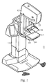
- a typical mammography apparatus 1 as presented in figure 1 consists of a body part 11 and a C-arm construction 12 connected to it.
- These depicting means 13, 15, being located inside the cover of the apparatus, are actually not visible in figure 1 .
- a means 16, 17 for positioning/locking the object to be imaged within the imaging area has been placed.
- this kind of an apparatus is motorized such that the C-arm 12 is arranged movable in a vertical direction and rotatable about an axis, typically a physical horizontal axis connecting the C-arm to the body part 11.
- the positioning/locking means 16, 17 typically consist of an upper compression plate 16 and a lower compression plate 17, which lower compression plate 17 may be arranged integrated with the lower shelf structure 14.
- a grid structure may be located above the image data receiving means 15, which grid structure limits entry of radiation scattered from the tissue to the image data receiving means 15.
- Figures 2a and 2b represent prior art systems to acquire image information for 3D mammography.
- Figs. 2a, 2b , 3a, 3b not an actual cone-shaped x-ray beam originating from the focus of the x-ray source 13 but only the central ray is shown.
- the x-ray source 13 is arranged to move in a continuous fashion from a starting position of the imaging procedure to an end position of the imaging procedure, and during this movement, the x-ray source 13 is energized for the duration of a number of short exposure periods, while the compression plates 16, 17 (and in Fig. 2a , also the detector 15) remain stationary.
- the image information detected at the detector 15 is stored and/or sent to image processing.
- use of a conventional anti-scatter grid is not possible as the grid would absorb a portion of the desired x-ray quanta as well at all the other exposure angles but that which is parallel with orientation of the grid lamella.
- the x-ray source 13 is moved in a stepwise manner such that for each exposure, the x-ray source is stopped at a predefined angular position.
- Fig. 2b three such stationary exposure positions of the x-ray source 13 are shown.
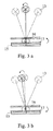
- Figures 3a and 3b show two basic operational phases of the current mammography imaging invention.
- Fig. 3a can be regarded as showing one exposure phase and Fig. 3b as showing one non-exposure phase of the system, together with the extreme positions of the x-ray source 13.
- these extreme positions of the x-ray source 13 with respect to the vertical indicate the width of the tomographic angle of the system
- Fig. 3a the two close to vertical positions of the x-ray source 13, and the corresponding positions of the breast locking means 16, 17 and the detector 15, depict the core operational phase of the system according to the invention
- Fig. 3b those of a certain preferable embodiment of the invention.
- the compression plates 16, 17 are arranged to turn as synchronized with the movement of the x-ray source 13, while during a non-exposure phase ( Fig. 3b ), they are turned in the opposite direction.
- the detector 15 is arranged to turn together with the compression plates 16, 17.
- the synchronized movement of the x-ray source 13 and the compression plates 16, 17 according to the invention makes possible avoiding creating such movement artefacts that are always present when the breast is imaged according to a prior art method of Fig 2a , where there is mutual movement between the x-ray source 13 and the breast during an exposure.
- the invention also makes possible using longer exposure times and does not necessitate using an extra-powerful and thus heavier x-ray source.
- preferable embodiments of the invention include an operational phase during which the x-ray source 15 is not energized (a non-irradiation period) and the compression plates 16, 17 (and the detector 15) are turned in the direction opposite to that of the movement of the x-ray source 13. According to the preferable embodiment of the invention as shown in Fig. 3b , the compression plates 16, 17 and the detector 15 are turned back to their initial position at the beginning of the preceding irradiation period.
- the angle through which the compression plates 16, 17 will be turned can be arranged to be very small and the periods of non-exposure to be longer than the exposure periods so that there will be plenty of time to establish a stable starting situation for a subsequent exposure period.
- there will be plenty of time for counter-turning the breast as the periods when the x-ray source 13 is not energized are arranged to be considerably longer than the periods during which it is energized.
- the compression plates 16, 17 could be turned through 2 degrees or even less, which would easily leave enough time for backwards turning even when taking into account the time needed for acceleration and deceleration of the movements.
- both the radiation source 13 and the image detector 15 are moved at the same essentially regular angular velocity around the breast whilst it is compressed between the compression plates 16, 17 - or locked otherwise in a means arranged for this purpose.
- the compression plates 16, 17, or said other locking means are turned as synchronized with the movement of the radiation source 13.
- the breast will remain still with respect to the radiation source 13 during each such irradiation period.
- the compression plates 16, 17 are turned back to their position at the beginning of the preceding irradiation period.
- the total angle the locking means 16, 17 shall turn needs to be only as small as the angle of turn needed for creating synchronization of movements during an individual exposure of one projection image.
- This angle may be arranged to be e.g.
- the breast to be imaged is arranged locked in a locking means 16, 17 and during the imaging process, an x-ray source 13 is moved with respect to the location of the breast to be imaged and the breast is irradiated during a number of irradiation periods which begin at a number of angular positions of the x-ray source 13.
- the x-ray source 13 is moved continuously and the breast is irradiated during a number of short irradiation periods and, during a period when the breast is being irradiated, the locking means 16, 17 is moved as synchronized with the movement of the x-ray source 13.
- a mammography apparatus comprises a body part 11 and arranged thereto an x-ray source 13, an image detector 15 as well as within an area between the x-ray source 13 and the image detector 15, a means arranged for locking a breast 16, 17, the x-ray source 13 being arranged movable with respect to the location of said locking means 16, 17. Further, the apparatus comprises a control system arranged to control operation of the apparatus.
- the locking means 16, 17 is arranged turnable and movement of the locking means 16, 17 and the x-ray source 13 is arranged motorised and the operation of the x-ray source controlled by said control system such that during an imaging process, the x-ray source 13 moves continuously and the breast is irradiated during a number of short irradiation periods and, during an irradiation period, said locking means 16, 17 turns as synchronized with the movement of the x-ray source 13.
- the imaging procedure may include a phase prior to the first irradiation period wherein said locking means 16, 17 is turned in a direction opposite to that when moved as synchronized with the movement of the x-ray source 13. There may be periods of backwards movement of the locking means 16, 17 in between any number of successive irradiation periods.
- the length of the turning-back movement of the locking means 16, 17 (and possibly also that of the image detector 15) may be either exactly the same as during an exposure period, i.e. the locking means 16, 17 may be moved back to its initial position at the beginning of a preceding exposure period, or the backwards movement may be shorter or longer than the one having taken place during a preceding exposure.
- the length of the backwards movement does not have to be any exact multiple of the steps of the movement during an exposure.
- the imaging procedure may consist of steps of two exposure periods between which the locking means 16, 17 do not turn in any direction, but after the second of these exposure periods, the backwards movement will correspond to the total movement of the locking means 16, 17 during these two exposure periods.
- the extreme positions of the x-ray source 13 with respect to the breast during the imaging process may be arranged to make up a tomographic angle of several tens of degrees, such as about 50 degrees.
- the overall movement of the x-ray source 13 is arranged to be symmetrical with respect to the vertical, i.e. the overall tomographic angle to be about plus-minus 25 degrees with respect to the vertical.
- the movement of the x-ray source 13 is arranged to follow a curved path as in the case of typical existing mammography apparatus, yet the principle of the invention may be realized also when moving the x-ray source linearly.
- the ratio between the angle of the minute individual turns of the locking means 16, 17 during exposure periods with respect to the overall displacement of the x-ray source 13 may be arranged to be of the order of 1/10.
- the imaging procedure may be arranged to consist of about 11-15 exposure periods.
- preferable embodiments of the invention include using an x-ray source 13 comprising a tungsten anode which, with proper arrangements such as using a selenium based imaging detector and especially a silver filter of proper thickness to absorb those low energy x-ray quanta which would not be able to penetrate the breast tissue, can result in a reduced radiation dose when compared to some other arrangements.
- exposure times for the projection images of around 50-100 ms may be used, and imaging parameter values for the x-ray tube voltage of around 35-40 kV, even up to 45 kV, and about 5 mAs. With kV values of about 30-34, mAs values of about 10-13 may be used.
- One preferable embodiment of the invention includes an arrangement in which in functional connection with the locking means, there has been arranged a means for pulling tissue into the space between the compression plates 16, 17.
- a means may be arranged to comprise e.g. an arrangement as shown in Fig. 4 , wherein an upper and a lower stretching device 30 are integrated with both of the compression plates 16, 17.
- the stretching devices 30 may be arranged to comprise a means for engaging and pulling a stretching means, such as a plastic sheet 31, so that in connection with compressing the breast between the compression plates 16, 17, breast tissue will be drawn in between the compression plates 16, 17 upon positioning of the breast for imaging.
- Such an arrangement enables using perhaps 10 % less compression in the context of the current invention than typically used in the art of mammography, which makes the imaging procedure including both compressing and turning a breast less awkward.
- the current invention is applicable for use both in the context of so called full-field sized and smaller imaging detectors used in mammography.
Landscapes
- Health & Medical Sciences (AREA)
- Life Sciences & Earth Sciences (AREA)
- Medical Informatics (AREA)
- Engineering & Computer Science (AREA)
- Radiology & Medical Imaging (AREA)
- Molecular Biology (AREA)
- Biophysics (AREA)
- Nuclear Medicine, Radiotherapy & Molecular Imaging (AREA)
- Optics & Photonics (AREA)
- Pathology (AREA)
- Physics & Mathematics (AREA)
- Biomedical Technology (AREA)
- Heart & Thoracic Surgery (AREA)
- High Energy & Nuclear Physics (AREA)
- Surgery (AREA)
- Animal Behavior & Ethology (AREA)
- General Health & Medical Sciences (AREA)
- Public Health (AREA)
- Veterinary Medicine (AREA)
- Dentistry (AREA)
- Oral & Maxillofacial Surgery (AREA)
- Apparatus For Radiation Diagnosis (AREA)
Claims (15)
- Mammographieabbildungsverfahren, bei dem eine Brust, die abgebildet werden soll, derart angeordnet ist, dass sie in einem Verriegelungsmittel (16,17) eingeschlossen ist innerhalb eines Bereichs zwischen einer Röntgenquelle (13) und einem Bilddetektor (15) einer Mammographievorrichtung
wobei während des Abbildungsprozesses, die Röntgenquelle (13), in Bezug auf die Lage der Brust bewegt wird und die Brust aus einer Anzahl von Winkelstellungen der Röntgenquelle (13) in Bezug auf die Lage der Brust bestrahlt wird,
dadurch gekennzeichnet, dass
sich während des Abbildungsprozesses die Röntgenquelle (13) fortlaufend bewegt und während einer Anzahl von kurzen Bestrahlungszeiträumen die Brust bestrahlt wird und,
während eines Bestrahlungszeitraumes das Verriegelungsmittel (16,17) abgestimmt auf die Bewegung der Röntgenquelle (13) gedreht wird, um die Bewegung derer zu verfolgen. - Verfahren nach Anspruch 1 dadurch gekennzeichnet, dass
vor dem ersten Bestrahlungszeitraum und/oder zwischen irgendwelchen nachfolgenden Bestrahlungszeiträumen, d.h. während einer Periode, wenn die Brust nicht bestrahlt wird, die Verriegelungseinrichtung (16,17) in einer Richtung gedreht wird, entgegengesetzt zu jener in die sie gedreht wird in Synchronisation mit der Bewegung der Röntgenquelle (13). - Verfahren nach Anspruch 1 oder 2 dadurch gekennzeichnet, dass
nach einem Bestrahlungszeitraum, während dessen die Bewegung des Verriegelungsmittels (16,17) synchron mit der Bewegung der Röntgenquelle (13) ist und vor zumindest einem nachfolgendem Bestrahlungszeitraum, das Verriegelungsmittel (16,17) zumindest im wesentlichen wieder in seine Anfangsposition gedreht wird, das heißt zumindest im wesentlichen in die Anfangsposition des vorangehenden Bestrahlungszeitraums, oder
dass der Abbildungsprozess eine Anzahl von Bestrahlungszeiträumen beinhaltet, während denen sich das Verriegelungsmittel (16,17) synchron zu den Bewegungen der Röntgenquelle (13) dreht, und während jedem nicht Bestrahlungszeitraum, anschließend an einen Bestrahlungszustand das Verriegelungsmittel (16,17) zumindest im wesentlichen zurück in die Anfangsposition eines solchen Bestrahlungszeitraums gedreht wird. - Verfahren nach einem der Ansprüche 1 bis 3 dadurch gekennzeichnet, dass
die Bewegung der Verriegelungseinrichtung (16,17) während einem Bestrahlungszeitraum die Bewegung des Verriegelungsmittels (16,17) um einen Winkel über 2 Grad oder weniger, wie zum Beispiel 0,5 bis 2 Grad, umfasst. - Verfahren nach einem der Ansprüche 1 bis 4 dadurch gekennzeichnet, dass
extreme Winkelstellungen der Röntgenquelle (13) im Bezug auf die Brust während des Abbildungsprozesses einen tomographischen Winkel von einigen zehn Grad bilden und/oder die Gesamtbewegung der Röntgenquelle (13) symmetrisch in Bezug zur Vertikalen eingerichtet ist. - Verfahren nach einem der Ansprüche 1 bis 5 dadurch gekennzeichnet, dass
die Bewegung der Röntgenquelle (13) so eingerichtet ist, dass sie einem gekrümmten Pfad über die Brust folgt. - Verfahren nach einem der Ansprüche 1 bis 6 dadurch gekennzeichnet, dass
das Verriegelungsmittel (16,17) Druckplatten( 16,17), zwischen denen die Brust für die Dauer des Abbildungsprozesses zusammengedrückt wird, aufweist, und/oder Streckmittel (30,31), geeignet, um Brustgewebe zwischen den Verriegelungsmitteln (16,17)/Druckplatten (16,17) zu ziehen. - Verfahren nach einem der Ansprüche 1 bis 7 dadurch gekennzeichnet, dass
während eines Bestrahlungszeitraumes die Röntgenquelle (13) abhängig von den Eigenschaften des Brustgewebes unter Verwendung der Bildparameterwerte für die Röntgenquelle betrieben wird, die eine Wolframanode von etwa 35 - 45 kV und 5 mAs oder etwa 30 bis 34 kV und 10 - 13 mAs beinhaltet. - Verfahren nach einem der Ansprüche 1 bis 8 dadurch gekennzeichnet, dass
das Verfahren ungefähr 11-15 Bestrahlungszeiträume umfasst und/oder
das Verhältnis zwischen dem Winkel, um den die Verriegelungsmittel (16,17) sich während einem Bestrahlungszeitraum bewegen, und den gesamt tomographischen Winkel des Abbildungsprozesses kleiner als 1 zu 10 ist. - Mammographievorrichtung mit einem Körperteil (11) und einer daran angeordneten Röntgenquelle (13), einen Bilddetektor (15) sowie in einem Raum zwischen der Röntgenquelle (13) und dem Bilddetektor (15) ein Mittel, angeordnet zum Verriegeln der Brust (16,17), wobei die Röntgenquell (13) beweglich im Bezug zur Lage des Verriegelungsmittels (16,17) angeordnet ist, wobei die Vorrichtung ferner ein Steuersystem hat, angeordnet zum Steuern der Vorrichtung
dadurch gekennzeichnet, dass
das Brustverriegelungsmittel (16,17) drehbar gelagert ist und die Bewegung des Verriegelungsmittels (16, 17) und der Röntgenquelle (13) motorisiert eingerichtet ist und der Betrieb der Röntgenquelle durch ein Steuersystem gesteuert wird, so dass sich die Röntgenquelle (13) während eines Bestrahlungsprozesses kontinuierlich bewegt und die Brust während einer Anzahl kurzer Bestrahlungszeiträume bestrahlt wird, wobei
während eines Bestrahlungszeitraumes sich das Verriegelungsmittel synchron mit der Bewegung der Röntgenquelle (13) dreht, um der Bewegung dieser zu folgen. - Mammographievorrichtung nach Anspruch 10 dadurch gekennzeichnet, dass
das Steuersystem eingerichtet ist, um den Betrieb der Vorrichtung zu steuern, so dass vor dem ersten Bestrahlungszeitraum und/oder zwischen irgendwelchen nachfolgenden Bestrahlungszeiträumen, d.h. während einer Periode, wenn die Brust nicht bestrahlt wird, das Verriegelungsmittel (16,17), in einer Richtung entgegengesetzt zu der wenn es synchron mit der Bewegung der Röntgenquelle (13) ist, dreht. - Mammographievorrichtung nach Anspruch 10 oder 11 dadurch gekennzeichnet, dass
das Steuersystem eingerichtet ist, um den Betrieb der Vorrichtung zu steuerni) so dass sich nach einem Bestrahlungszeitraum, während dessen das Verriegelungsmittel (16,17) synchron zur Bewegung der Röntgenquelle bewegt wird und vor mindestens einem nachfolgenden Bestrahlungszeitraum, das Verriegelungsmittel zumindest im Wesentlichen zurück in die Anfangsposition dreht, das heißt, zumindest im Wesentlichen in die Position zu Anfang des vorhergehenden Bestrahlungszeitraums oderii) so dass eine Anzahl von Bestrahlungszeiträumen, während welchen das Verriegelungsmittel (16, 17) sich synchron zur Bewegung der Röntgenquelle (13) dreht, und während jedem nicht Bestrahlungszeitraum im Anschluss an einen solchen Bestrahlungszeitraum, sich das Verriegelungsmittel (16,17) zumindest im Wesentlichen zurück in die Anfangsposition des vorhergehenden Bestrahlungszeitraums dreht. - Mammographievorrichtung nach einem der Ansprüche 10 bis 12 dadurch gekennzeichnet, dass
das Steuersystem eingerichtet ist, um den Betrieb der Vorrichtung zu steuern, so dass das Verriegelungsmittel (16,17) sich während eines Bestrahlungszeitraums um einen Winkel von 2 Grad oder weniger, wie zum Beispiel über 0,5 bis2 Grad, dreht. - Mammographievorrichtung nach einem der Ansprüche 10 bis 13 dadurch gekennzeichnet, dass
die Bewegung der Röntgenquelle (13) so eingerichtet ist, dass sie einem gekrümmten Pfad über die Brust, positioniert im Brustverriegelungsmittel (16,17), folgt. - Mammographievorrichtung nach einem der Ansprüche 10 bis 13 dadurch gekennzeichnet, dass
das Verriegelungsmittel (16,17) Druckplatten( 16,17), zwischen denen die Brust für die Dauer des Abbildungsprozesses zusammengedrückt wird, aufweist, und/oder Streckmittel (30,31) an der Vorrichtung zum Ziehen des Brustgewebes zwischen den Verriegelungsmitteln(16, 17)/Druckplatten (16,17) eingerichtet wurden.
Applications Claiming Priority (2)
| Application Number | Priority Date | Filing Date | Title |
|---|---|---|---|
| FI20080639A FI123261B (fi) | 2008-11-28 | 2008-11-28 | 3D mammografia |
| PCT/FI2009/050963 WO2010061062A1 (en) | 2008-11-28 | 2009-11-30 | 3d mammography |
Publications (3)
| Publication Number | Publication Date |
|---|---|
| EP2369996A1 EP2369996A1 (de) | 2011-10-05 |
| EP2369996A4 EP2369996A4 (de) | 2012-07-04 |
| EP2369996B1 true EP2369996B1 (de) | 2014-02-26 |
Family
ID=40097280
Family Applications (2)
| Application Number | Title | Priority Date | Filing Date |
|---|---|---|---|
| EP09799297.8A Active EP2369995B1 (de) | 2008-11-28 | 2009-11-30 | Medizinische radiografie in 3d |
| EP09828703.0A Not-in-force EP2369996B1 (de) | 2008-11-28 | 2009-11-30 | 3d-mammografie |
Family Applications Before (1)
| Application Number | Title | Priority Date | Filing Date |
|---|---|---|---|
| EP09799297.8A Active EP2369995B1 (de) | 2008-11-28 | 2009-11-30 | Medizinische radiografie in 3d |
Country Status (8)
| Country | Link |
|---|---|
| US (3) | US8693623B2 (de) |
| EP (2) | EP2369995B1 (de) |
| JP (3) | JP5762302B2 (de) |
| KR (2) | KR101443956B1 (de) |
| CN (2) | CN102264297B (de) |
| ES (2) | ES2505326T3 (de) |
| FI (1) | FI123261B (de) |
| WO (2) | WO2010061062A1 (de) |
Families Citing this family (24)
| Publication number | Priority date | Publication date | Assignee | Title |
|---|---|---|---|---|
| FI123261B (fi) | 2008-11-28 | 2013-01-15 | Planmed Oy | 3D mammografia |
| KR20110138803A (ko) * | 2010-06-22 | 2011-12-28 | 삼성전자주식회사 | X-ray를 이용한 영상 진단 장치 및 방법 |
| KR101174351B1 (ko) | 2010-07-22 | 2012-08-23 | 한국전기연구원 | 디지털 x―선 이미징을 위한 단층영상합성 시스템 및 그 제어 방법 |
| EP2624761B1 (de) | 2010-10-05 | 2021-07-14 | Hologic, Inc. | Bruströntgenbildgebung in aufrechter position mit einem ct-modus, mehreren tomosynthese-modi und einem mammographie-modus |
| WO2015054518A1 (en) | 2013-10-09 | 2015-04-16 | Hologic, Inc | X-ray breast tomosynthesis enhancing spatial resolution including in the thickness direction of a flattened breast |
| USD739534S1 (en) * | 2011-10-05 | 2015-09-22 | General Electric Company | Tomosynthesis device |
| JP6157491B2 (ja) | 2011-11-18 | 2017-07-05 | ホロジック, インコーポレイテッドHologic, Inc. | 造影と患者の快適性とを改善する膨張性ジャケットを備えた圧迫パドルを用いたx線マンモグラフィーおよび/または乳房トモシンセシス |
| US11259759B2 (en) | 2011-11-18 | 2022-03-01 | Hologic Inc. | X-ray mammography and/or breast tomosynthesis using a compression paddle |
| US9517038B2 (en) * | 2012-10-12 | 2016-12-13 | University Of Virginia Patent Foundation | Apparatus and method for breast immobilization |
| CN105228526B (zh) * | 2013-03-29 | 2018-06-08 | 通用电气公司 | 乳房造影装置 |
| US10130322B2 (en) * | 2013-03-29 | 2018-11-20 | General Electric Company | Mammography device and method of controlling position alignment thereof |
| DE102013013414B3 (de) | 2013-08-09 | 2015-01-29 | Fresenius Medical Care Deutschland Gmbh | Kassettenmodul |
| FI130432B (fi) | 2013-11-29 | 2023-08-28 | Planmed Oy | Tomosynteesikalibrointi mammografian yhteydessä |
| FI126217B (fi) * | 2013-11-29 | 2016-08-31 | Planmed Oy | Mammografialaite |
| EP3215017B1 (de) * | 2014-11-07 | 2021-01-06 | Hologic, Inc. | Schwenkbare paddelvorrichtung für mammografie/tomosynthese-röntgensystem |
| US9943280B2 (en) * | 2016-03-07 | 2018-04-17 | General Electric Company | Breast tomosynthesis with flexible compression paddle |
| EP3868302B1 (de) | 2016-11-08 | 2023-12-06 | Hologic, Inc. | Bildgebung mit gekrümmten kompressionselementen |
| EP3664713A4 (de) | 2017-08-11 | 2021-04-28 | Hologic, Inc. | Brustkompressionsplatte mit zugangsecken |
| ES3014459T3 (en) | 2017-08-11 | 2025-04-22 | Hologic Inc | Breast compression paddle |
| DE202018006903U1 (de) | 2017-08-16 | 2024-07-29 | Hologic Inc. | Techniken zur Patientenbewegungsartefaktkompensation bei Brustbildgebung |
| JP7742349B2 (ja) | 2020-01-24 | 2025-09-19 | ホロジック, インコーポレイテッド | 水平に変位可能な発泡体乳房圧迫パドル |
| TWI788689B (zh) * | 2020-07-27 | 2023-01-01 | 財團法人資訊工業策進會 | 三維乳房影像之物件偵測方法、物件偵測系統及非暫態電腦可讀取記錄媒體 |
| CN112107324B (zh) * | 2020-09-03 | 2024-04-26 | 上海联影医疗科技股份有限公司 | 数字乳腺断层摄影设备的扫描方法、介质及医疗设备 |
| KR20240000563A (ko) | 2021-04-26 | 2024-01-02 | 홀로직, 인크. | 폼 압축 요소들의 두께를 측정하기 위한 시스템들 및 방법들 |
Family Cites Families (27)
| Publication number | Priority date | Publication date | Assignee | Title |
|---|---|---|---|---|
| BE791850A (fr) | 1971-11-26 | 1973-05-24 | Cfc Products | Procede et dispositif de tomographie |
| US3984684A (en) | 1974-02-06 | 1976-10-05 | Douglas Fredwill Winnek | Three-dimensional radiography |
| SE459150B (sv) | 1986-09-19 | 1989-06-12 | Anders Wallner | Anordning foer mammografisk stereotaktisk punktion av patologiska foeraendringar i det kvinnliga broestet |
| US4789929A (en) * | 1987-05-14 | 1988-12-06 | Hitachi Medical Corporation | CT system for spirally scanning subject on a movable bed synchronized to X-ray tube revolution |
| FI80996C (fi) | 1988-05-26 | 1991-10-25 | Automed Oy | Mammografiamenetelmä ja -laite |
| IT1234033B (it) | 1989-03-17 | 1992-04-24 | I M S Internazionale Medico Sc | Apparecchiatura per eseguire mammografie |
| JP2914891B2 (ja) | 1995-07-05 | 1999-07-05 | 株式会社東芝 | X線コンピュータ断層撮影装置 |
| FI106293B (fi) * | 1998-11-27 | 2001-01-15 | Planmed Oy | Menetelmä ja laitteet kudosten kuvantamisessa |
| FR2829918A1 (fr) * | 2001-09-25 | 2003-03-28 | Ge Med Sys Global Tech Co Llc | Appareil de mammographie |
| US20030149364A1 (en) * | 2002-02-01 | 2003-08-07 | Ajay Kapur | Methods, system and apparatus for digital imaging |
| JP3658389B2 (ja) | 2002-11-18 | 2005-06-08 | キヤノン株式会社 | 放射線撮影装置 |
| US7831296B2 (en) * | 2002-11-27 | 2010-11-09 | Hologic, Inc. | X-ray mammography with tomosynthesis |
| JP2004202119A (ja) * | 2002-12-26 | 2004-07-22 | Konica Minolta Holdings Inc | 乳房画像撮影装置 |
| JP2004236915A (ja) * | 2003-02-07 | 2004-08-26 | Hitachi Medical Corp | X線ct装置 |
| EP1618411A4 (de) * | 2003-04-11 | 2012-04-25 | Fischer Imaging Corp | Streuungsunterdrückung für zusammengesetzte medizinische abbildungssysteme |
| US7092482B2 (en) * | 2003-04-11 | 2006-08-15 | Fischer Imaging Corporation | Signal profiling for medical imaging systems |
| DE10353611B4 (de) * | 2003-11-17 | 2013-01-17 | Siemens Aktiengesellschaft | Röntgendiagnostikgerät für Mammographieuntersuchungen |
| FI118322B (fi) | 2003-11-28 | 2007-10-15 | Planmed Oy | Mammografiakuvauslaite |
| FR2875693B1 (fr) * | 2004-09-24 | 2006-12-08 | Gen Electric | Dispositif de tomographie par rayons x |
| EP3106094B1 (de) | 2004-11-26 | 2021-09-08 | Hologic, Inc. | Integriertes multimodus-mammographie-/tomosynthese-röntgensystem |
| FR2890553B1 (fr) * | 2005-09-13 | 2007-11-23 | Gen Electric | Dispositif de rayonnement x mixte |
| US7302031B2 (en) | 2005-10-27 | 2007-11-27 | Sectra Mamea Ab | Method and arrangement relating to X-ray imaging |
| US20070198448A1 (en) * | 2006-02-21 | 2007-08-23 | International Business Machines Corporation | Scalable ontology reasoning |
| JP4851296B2 (ja) * | 2006-10-26 | 2012-01-11 | 富士フイルム株式会社 | 放射線断層画像取得装置および放射線断層画像取得方法 |
| US7676019B2 (en) | 2007-01-31 | 2010-03-09 | Sectra Mamea Ab | Compression arrangement |
| JP2010158257A (ja) * | 2007-04-10 | 2010-07-22 | Konica Minolta Medical & Graphic Inc | 放射線画像撮影装置および放射線画像撮影システム |
| FI123261B (fi) * | 2008-11-28 | 2013-01-15 | Planmed Oy | 3D mammografia |
-
2008
- 2008-11-28 FI FI20080639A patent/FI123261B/fi not_active IP Right Cessation
-
2009
- 2009-11-30 EP EP09799297.8A patent/EP2369995B1/de active Active
- 2009-11-30 EP EP09828703.0A patent/EP2369996B1/de not_active Not-in-force
- 2009-11-30 KR KR1020117014815A patent/KR101443956B1/ko not_active Expired - Fee Related
- 2009-11-30 JP JP2011538016A patent/JP5762302B2/ja not_active Expired - Fee Related
- 2009-11-30 ES ES09799297.8T patent/ES2505326T3/es active Active
- 2009-11-30 JP JP2011537997A patent/JP5709757B2/ja active Active
- 2009-11-30 US US13/131,354 patent/US8693623B2/en active Active
- 2009-11-30 WO PCT/FI2009/050963 patent/WO2010061062A1/en not_active Ceased
- 2009-11-30 US US13/131,365 patent/US8532253B2/en not_active Expired - Fee Related
- 2009-11-30 CN CN200980153101.XA patent/CN102264297B/zh not_active Expired - Fee Related
- 2009-11-30 ES ES09828703.0T patent/ES2463822T3/es active Active
- 2009-11-30 KR KR1020117014817A patent/KR101631343B1/ko active Active
- 2009-11-30 CN CN200980153102.4A patent/CN102264298B/zh active Active
- 2009-11-30 WO PCT/EP2009/066051 patent/WO2010061003A1/en not_active Ceased
-
2013
- 2013-08-08 US US13/962,545 patent/US8848866B2/en active Active
-
2015
- 2015-01-26 JP JP2015012053A patent/JP2015077479A/ja active Pending
Also Published As
| Publication number | Publication date |
|---|---|
| US8848866B2 (en) | 2014-09-30 |
| US8693623B2 (en) | 2014-04-08 |
| CN102264298A (zh) | 2011-11-30 |
| WO2010061062A1 (en) | 2010-06-03 |
| KR20110089445A (ko) | 2011-08-08 |
| CN102264297A (zh) | 2011-11-30 |
| EP2369995A1 (de) | 2011-10-05 |
| US20140003574A1 (en) | 2014-01-02 |
| JP2015077479A (ja) | 2015-04-23 |
| US8532253B2 (en) | 2013-09-10 |
| US20110222653A1 (en) | 2011-09-15 |
| FI20080639A0 (fi) | 2008-11-28 |
| KR101443956B1 (ko) | 2014-09-23 |
| FI123261B (fi) | 2013-01-15 |
| ES2463822T3 (es) | 2014-05-29 |
| WO2010061003A1 (en) | 2010-06-03 |
| JP5709757B2 (ja) | 2015-04-30 |
| EP2369996A4 (de) | 2012-07-04 |
| HK1160747A1 (en) | 2012-08-17 |
| ES2505326T3 (es) | 2014-10-09 |
| KR101631343B1 (ko) | 2016-06-16 |
| JP5762302B2 (ja) | 2015-08-12 |
| EP2369996A1 (de) | 2011-10-05 |
| CN102264297B (zh) | 2014-07-23 |
| JP2012510305A (ja) | 2012-05-10 |
| FI20080639L (fi) | 2010-08-16 |
| EP2369995B1 (de) | 2014-07-30 |
| CN102264298B (zh) | 2014-02-05 |
| JP2012510304A (ja) | 2012-05-10 |
| US20110228902A1 (en) | 2011-09-22 |
| KR20110089446A (ko) | 2011-08-08 |
Similar Documents
| Publication | Publication Date | Title |
|---|---|---|
| EP2369996B1 (de) | 3d-mammografie | |
| JP5319878B2 (ja) | 患者胸部のx線マンモグラフィ/トモシンセシス | |
| KR102023549B1 (ko) | 디지털 방사선 촬영 장치 및 방법 | |
| US7885378B2 (en) | Imaging system and related techniques | |
| CN101808582B (zh) | 用于x射线断层造影合成的系统和方法 | |
| EP3073925B1 (de) | Mammographiebildgebungsanordnung für tomosynthese | |
| US20120224664A1 (en) | Tomosynthesis mammography system with enlarged field of view | |
| JP4672099B2 (ja) | X線診断装置 | |
| US7418076B2 (en) | System and method for cross table tomosynthesis imaging for trauma applications | |
| KR101531370B1 (ko) | 엑스선 영상장치 및 엑스선 영상장치의 이미징 방법 | |
| JP4734463B2 (ja) | X線診断装置 | |
| HK1160747B (en) | 3d mammography | |
| US11523787B2 (en) | Digital breast tomosynthesis device capable of controlling position of X-ray focus |
Legal Events
| Date | Code | Title | Description |
|---|---|---|---|
| PUAI | Public reference made under article 153(3) epc to a published international application that has entered the european phase |
Free format text: ORIGINAL CODE: 0009012 |
|
| 17P | Request for examination filed |
Effective date: 20110628 |
|
| AK | Designated contracting states |
Kind code of ref document: A1 Designated state(s): AT BE BG CH CY CZ DE DK EE ES FI FR GB GR HR HU IE IS IT LI LT LU LV MC MK MT NL NO PL PT RO SE SI SK SM TR |
|
| DAX | Request for extension of the european patent (deleted) | ||
| A4 | Supplementary search report drawn up and despatched |
Effective date: 20120601 |
|
| RIC1 | Information provided on ipc code assigned before grant |
Ipc: A61B 6/00 20060101AFI20120525BHEP Ipc: A61B 6/04 20060101ALI20120525BHEP |
|
| 17Q | First examination report despatched |
Effective date: 20120709 |
|
| GRAP | Despatch of communication of intention to grant a patent |
Free format text: ORIGINAL CODE: EPIDOSNIGR1 |
|
| INTG | Intention to grant announced |
Effective date: 20130904 |
|
| GRAS | Grant fee paid |
Free format text: ORIGINAL CODE: EPIDOSNIGR3 |
|
| GRAA | (expected) grant |
Free format text: ORIGINAL CODE: 0009210 |
|
| AK | Designated contracting states |
Kind code of ref document: B1 Designated state(s): AT BE BG CH CY CZ DE DK EE ES FI FR GB GR HR HU IE IS IT LI LT LU LV MC MK MT NL NO PL PT RO SE SI SK SM TR |
|
| REG | Reference to a national code |
Ref country code: GB Ref legal event code: FG4D |
|
| REG | Reference to a national code |
Ref country code: CH Ref legal event code: EP |
|
| REG | Reference to a national code |
Ref country code: AT Ref legal event code: REF Ref document number: 653081 Country of ref document: AT Kind code of ref document: T Effective date: 20140315 |
|
| REG | Reference to a national code |
Ref country code: DE Ref legal event code: R096 Ref document number: 602009022099 Country of ref document: DE Effective date: 20140403 |
|
| REG | Reference to a national code |
Ref country code: IE Ref legal event code: FG4D |
|
| REG | Reference to a national code |
Ref country code: ES Ref legal event code: FG2A Ref document number: 2463822 Country of ref document: ES Kind code of ref document: T3 Effective date: 20140529 |
|
| REG | Reference to a national code |
Ref country code: SE Ref legal event code: TRGR |
|
| REG | Reference to a national code |
Ref country code: NL Ref legal event code: VDEP Effective date: 20140226 |
|
| REG | Reference to a national code |
Ref country code: AT Ref legal event code: MK05 Ref document number: 653081 Country of ref document: AT Kind code of ref document: T Effective date: 20140226 |
|
| REG | Reference to a national code |
Ref country code: LT Ref legal event code: MG4D |
|
| PG25 | Lapsed in a contracting state [announced via postgrant information from national office to epo] |
Ref country code: IS Free format text: LAPSE BECAUSE OF FAILURE TO SUBMIT A TRANSLATION OF THE DESCRIPTION OR TO PAY THE FEE WITHIN THE PRESCRIBED TIME-LIMIT Effective date: 20140626 Ref country code: LT Free format text: LAPSE BECAUSE OF FAILURE TO SUBMIT A TRANSLATION OF THE DESCRIPTION OR TO PAY THE FEE WITHIN THE PRESCRIBED TIME-LIMIT Effective date: 20140226 Ref country code: NO Free format text: LAPSE BECAUSE OF FAILURE TO SUBMIT A TRANSLATION OF THE DESCRIPTION OR TO PAY THE FEE WITHIN THE PRESCRIBED TIME-LIMIT Effective date: 20140526 |
|
| PG25 | Lapsed in a contracting state [announced via postgrant information from national office to epo] |
Ref country code: CY Free format text: LAPSE BECAUSE OF FAILURE TO SUBMIT A TRANSLATION OF THE DESCRIPTION OR TO PAY THE FEE WITHIN THE PRESCRIBED TIME-LIMIT Effective date: 20140226 Ref country code: AT Free format text: LAPSE BECAUSE OF FAILURE TO SUBMIT A TRANSLATION OF THE DESCRIPTION OR TO PAY THE FEE WITHIN THE PRESCRIBED TIME-LIMIT Effective date: 20140226 Ref country code: NL Free format text: LAPSE BECAUSE OF FAILURE TO SUBMIT A TRANSLATION OF THE DESCRIPTION OR TO PAY THE FEE WITHIN THE PRESCRIBED TIME-LIMIT Effective date: 20140226 Ref country code: PT Free format text: LAPSE BECAUSE OF FAILURE TO SUBMIT A TRANSLATION OF THE DESCRIPTION OR TO PAY THE FEE WITHIN THE PRESCRIBED TIME-LIMIT Effective date: 20140626 |
|
| PG25 | Lapsed in a contracting state [announced via postgrant information from national office to epo] |
Ref country code: LV Free format text: LAPSE BECAUSE OF FAILURE TO SUBMIT A TRANSLATION OF THE DESCRIPTION OR TO PAY THE FEE WITHIN THE PRESCRIBED TIME-LIMIT Effective date: 20140226 Ref country code: BE Free format text: LAPSE BECAUSE OF FAILURE TO SUBMIT A TRANSLATION OF THE DESCRIPTION OR TO PAY THE FEE WITHIN THE PRESCRIBED TIME-LIMIT Effective date: 20140226 Ref country code: HR Free format text: LAPSE BECAUSE OF FAILURE TO SUBMIT A TRANSLATION OF THE DESCRIPTION OR TO PAY THE FEE WITHIN THE PRESCRIBED TIME-LIMIT Effective date: 20140226 |
|
| PG25 | Lapsed in a contracting state [announced via postgrant information from national office to epo] |
Ref country code: CZ Free format text: LAPSE BECAUSE OF FAILURE TO SUBMIT A TRANSLATION OF THE DESCRIPTION OR TO PAY THE FEE WITHIN THE PRESCRIBED TIME-LIMIT Effective date: 20140226 Ref country code: RO Free format text: LAPSE BECAUSE OF FAILURE TO SUBMIT A TRANSLATION OF THE DESCRIPTION OR TO PAY THE FEE WITHIN THE PRESCRIBED TIME-LIMIT Effective date: 20140226 Ref country code: DK Free format text: LAPSE BECAUSE OF FAILURE TO SUBMIT A TRANSLATION OF THE DESCRIPTION OR TO PAY THE FEE WITHIN THE PRESCRIBED TIME-LIMIT Effective date: 20140226 Ref country code: EE Free format text: LAPSE BECAUSE OF FAILURE TO SUBMIT A TRANSLATION OF THE DESCRIPTION OR TO PAY THE FEE WITHIN THE PRESCRIBED TIME-LIMIT Effective date: 20140226 |
|
| REG | Reference to a national code |
Ref country code: DE Ref legal event code: R097 Ref document number: 602009022099 Country of ref document: DE |
|
| PG25 | Lapsed in a contracting state [announced via postgrant information from national office to epo] |
Ref country code: SK Free format text: LAPSE BECAUSE OF FAILURE TO SUBMIT A TRANSLATION OF THE DESCRIPTION OR TO PAY THE FEE WITHIN THE PRESCRIBED TIME-LIMIT Effective date: 20140226 Ref country code: PL Free format text: LAPSE BECAUSE OF FAILURE TO SUBMIT A TRANSLATION OF THE DESCRIPTION OR TO PAY THE FEE WITHIN THE PRESCRIBED TIME-LIMIT Effective date: 20140226 |
|
| PLBE | No opposition filed within time limit |
Free format text: ORIGINAL CODE: 0009261 |
|
| STAA | Information on the status of an ep patent application or granted ep patent |
Free format text: STATUS: NO OPPOSITION FILED WITHIN TIME LIMIT |
|
| 26N | No opposition filed |
Effective date: 20141127 |
|
| REG | Reference to a national code |
Ref country code: DE Ref legal event code: R097 Ref document number: 602009022099 Country of ref document: DE Effective date: 20141127 |
|
| PG25 | Lapsed in a contracting state [announced via postgrant information from national office to epo] |
Ref country code: SI Free format text: LAPSE BECAUSE OF FAILURE TO SUBMIT A TRANSLATION OF THE DESCRIPTION OR TO PAY THE FEE WITHIN THE PRESCRIBED TIME-LIMIT Effective date: 20140226 |
|
| PG25 | Lapsed in a contracting state [announced via postgrant information from national office to epo] |
Ref country code: LU Free format text: LAPSE BECAUSE OF FAILURE TO SUBMIT A TRANSLATION OF THE DESCRIPTION OR TO PAY THE FEE WITHIN THE PRESCRIBED TIME-LIMIT Effective date: 20141130 Ref country code: MC Free format text: LAPSE BECAUSE OF FAILURE TO SUBMIT A TRANSLATION OF THE DESCRIPTION OR TO PAY THE FEE WITHIN THE PRESCRIBED TIME-LIMIT Effective date: 20140226 |
|
| REG | Reference to a national code |
Ref country code: CH Ref legal event code: PL |
|
| GBPC | Gb: european patent ceased through non-payment of renewal fee |
Effective date: 20141130 |
|
| PG25 | Lapsed in a contracting state [announced via postgrant information from national office to epo] |
Ref country code: CH Free format text: LAPSE BECAUSE OF NON-PAYMENT OF DUE FEES Effective date: 20141130 Ref country code: LI Free format text: LAPSE BECAUSE OF NON-PAYMENT OF DUE FEES Effective date: 20141130 |
|
| REG | Reference to a national code |
Ref country code: FR Ref legal event code: PLFP Year of fee payment: 7 |
|
| PG25 | Lapsed in a contracting state [announced via postgrant information from national office to epo] |
Ref country code: IE Free format text: LAPSE BECAUSE OF NON-PAYMENT OF DUE FEES Effective date: 20141130 Ref country code: GB Free format text: LAPSE BECAUSE OF NON-PAYMENT OF DUE FEES Effective date: 20141130 |
|
| PG25 | Lapsed in a contracting state [announced via postgrant information from national office to epo] |
Ref country code: SM Free format text: LAPSE BECAUSE OF FAILURE TO SUBMIT A TRANSLATION OF THE DESCRIPTION OR TO PAY THE FEE WITHIN THE PRESCRIBED TIME-LIMIT Effective date: 20140226 |
|
| PG25 | Lapsed in a contracting state [announced via postgrant information from national office to epo] |
Ref country code: GR Free format text: LAPSE BECAUSE OF FAILURE TO SUBMIT A TRANSLATION OF THE DESCRIPTION OR TO PAY THE FEE WITHIN THE PRESCRIBED TIME-LIMIT Effective date: 20140527 Ref country code: BG Free format text: LAPSE BECAUSE OF FAILURE TO SUBMIT A TRANSLATION OF THE DESCRIPTION OR TO PAY THE FEE WITHIN THE PRESCRIBED TIME-LIMIT Effective date: 20140226 |
|
| PG25 | Lapsed in a contracting state [announced via postgrant information from national office to epo] |
Ref country code: MT Free format text: LAPSE BECAUSE OF FAILURE TO SUBMIT A TRANSLATION OF THE DESCRIPTION OR TO PAY THE FEE WITHIN THE PRESCRIBED TIME-LIMIT Effective date: 20140226 Ref country code: TR Free format text: LAPSE BECAUSE OF FAILURE TO SUBMIT A TRANSLATION OF THE DESCRIPTION OR TO PAY THE FEE WITHIN THE PRESCRIBED TIME-LIMIT Effective date: 20140226 Ref country code: HU Free format text: LAPSE BECAUSE OF FAILURE TO SUBMIT A TRANSLATION OF THE DESCRIPTION OR TO PAY THE FEE WITHIN THE PRESCRIBED TIME-LIMIT; INVALID AB INITIO Effective date: 20091130 |
|
| REG | Reference to a national code |
Ref country code: FR Ref legal event code: PLFP Year of fee payment: 8 |
|
| REG | Reference to a national code |
Ref country code: FR Ref legal event code: PLFP Year of fee payment: 9 |
|
| PG25 | Lapsed in a contracting state [announced via postgrant information from national office to epo] |
Ref country code: MK Free format text: LAPSE BECAUSE OF FAILURE TO SUBMIT A TRANSLATION OF THE DESCRIPTION OR TO PAY THE FEE WITHIN THE PRESCRIBED TIME-LIMIT Effective date: 20140226 |
|
| REG | Reference to a national code |
Ref country code: FR Ref legal event code: PLFP Year of fee payment: 10 |
|
| PGFP | Annual fee paid to national office [announced via postgrant information from national office to epo] |
Ref country code: FI Payment date: 20191023 Year of fee payment: 11 Ref country code: SE Payment date: 20191025 Year of fee payment: 11 |
|
| REG | Reference to a national code |
Ref country code: FI Ref legal event code: MAE |
|
| PG25 | Lapsed in a contracting state [announced via postgrant information from national office to epo] |
Ref country code: FI Free format text: LAPSE BECAUSE OF NON-PAYMENT OF DUE FEES Effective date: 20201130 |
|
| REG | Reference to a national code |
Ref country code: SE Ref legal event code: EUG |
|
| PG25 | Lapsed in a contracting state [announced via postgrant information from national office to epo] |
Ref country code: SE Free format text: LAPSE BECAUSE OF NON-PAYMENT OF DUE FEES Effective date: 20201201 |
|
| PGFP | Annual fee paid to national office [announced via postgrant information from national office to epo] |
Ref country code: ES Payment date: 20211203 Year of fee payment: 13 |
|
| PGFP | Annual fee paid to national office [announced via postgrant information from national office to epo] |
Ref country code: IT Payment date: 20211117 Year of fee payment: 13 |
|
| PG25 | Lapsed in a contracting state [announced via postgrant information from national office to epo] |
Ref country code: IT Free format text: LAPSE BECAUSE OF NON-PAYMENT OF DUE FEES Effective date: 20221130 |
|
| REG | Reference to a national code |
Ref country code: ES Ref legal event code: FD2A Effective date: 20240104 |
|
| PG25 | Lapsed in a contracting state [announced via postgrant information from national office to epo] |
Ref country code: ES Free format text: LAPSE BECAUSE OF NON-PAYMENT OF DUE FEES Effective date: 20221201 |
|
| PG25 | Lapsed in a contracting state [announced via postgrant information from national office to epo] |
Ref country code: ES Free format text: LAPSE BECAUSE OF NON-PAYMENT OF DUE FEES Effective date: 20221201 |
|
| PGFP | Annual fee paid to national office [announced via postgrant information from national office to epo] |
Ref country code: FR Payment date: 20231020 Year of fee payment: 15 Ref country code: DE Payment date: 20231019 Year of fee payment: 15 |
|
| REG | Reference to a national code |
Ref country code: DE Ref legal event code: R119 Ref document number: 602009022099 Country of ref document: DE |
|
| PG25 | Lapsed in a contracting state [announced via postgrant information from national office to epo] |
Ref country code: DE Free format text: LAPSE BECAUSE OF NON-PAYMENT OF DUE FEES Effective date: 20250603 |
|
| PG25 | Lapsed in a contracting state [announced via postgrant information from national office to epo] |
Ref country code: FR Free format text: LAPSE BECAUSE OF NON-PAYMENT OF DUE FEES Effective date: 20241130 |