EP2370129B1 - Anästhesiespritze mit einem längsverschieblichen vorschubkolben sowie rückschlagventil mit durchlass und sperrrichtung - Google Patents
Anästhesiespritze mit einem längsverschieblichen vorschubkolben sowie rückschlagventil mit durchlass und sperrrichtung Download PDFInfo
- Publication number
- EP2370129B1 EP2370129B1 EP09804185.8A EP09804185A EP2370129B1 EP 2370129 B1 EP2370129 B1 EP 2370129B1 EP 09804185 A EP09804185 A EP 09804185A EP 2370129 B1 EP2370129 B1 EP 2370129B1
- Authority
- EP
- European Patent Office
- Prior art keywords
- syringe according
- hydraulic
- syringe
- check valve
- gas
- Prior art date
- Legal status (The legal status is an assumption and is not a legal conclusion. Google has not performed a legal analysis and makes no representation as to the accuracy of the status listed.)
- Not-in-force
Links
- 230000003444 anaesthetic effect Effects 0.000 title description 17
- 230000000903 blocking effect Effects 0.000 title 1
- 238000007789 sealing Methods 0.000 claims description 15
- 238000003860 storage Methods 0.000 claims description 10
- 238000013022 venting Methods 0.000 claims description 4
- 230000007246 mechanism Effects 0.000 claims description 3
- 238000000926 separation method Methods 0.000 claims description 3
- 230000001105 regulatory effect Effects 0.000 claims description 2
- 206010002091 Anaesthesia Diseases 0.000 claims 1
- 230000037005 anaesthesia Effects 0.000 claims 1
- 239000007789 gas Substances 0.000 description 44
- 239000012530 fluid Substances 0.000 description 8
- 239000010720 hydraulic oil Substances 0.000 description 8
- 230000006835 compression Effects 0.000 description 7
- 238000007906 compression Methods 0.000 description 7
- 238000002347 injection Methods 0.000 description 7
- 239000007924 injection Substances 0.000 description 7
- 239000004810 polytetrafluoroethylene Substances 0.000 description 5
- 229920001343 polytetrafluoroethylene Polymers 0.000 description 5
- IJGRMHOSHXDMSA-UHFFFAOYSA-N Atomic nitrogen Chemical compound N#N IJGRMHOSHXDMSA-UHFFFAOYSA-N 0.000 description 4
- 230000006870 function Effects 0.000 description 4
- 239000011521 glass Substances 0.000 description 4
- 239000012528 membrane Substances 0.000 description 4
- 230000000694 effects Effects 0.000 description 3
- 239000007788 liquid Substances 0.000 description 3
- 238000000034 method Methods 0.000 description 3
- 239000000523 sample Substances 0.000 description 3
- 229920006169 Perfluoroelastomer Polymers 0.000 description 2
- 241001422033 Thestylus Species 0.000 description 2
- 238000007872 degassing Methods 0.000 description 2
- 230000001419 dependent effect Effects 0.000 description 2
- 230000000881 depressing effect Effects 0.000 description 2
- 239000003814 drug Substances 0.000 description 2
- 229910052757 nitrogen Inorganic materials 0.000 description 2
- 230000003287 optical effect Effects 0.000 description 2
- 230000008569 process Effects 0.000 description 2
- 241001465754 Metazoa Species 0.000 description 1
- 230000009471 action Effects 0.000 description 1
- 230000002457 bidirectional effect Effects 0.000 description 1
- 230000008859 change Effects 0.000 description 1
- 238000012790 confirmation Methods 0.000 description 1
- 238000010586 diagram Methods 0.000 description 1
- 229940079593 drug Drugs 0.000 description 1
- 229920001973 fluoroelastomer Polymers 0.000 description 1
- 238000002309 gasification Methods 0.000 description 1
- 238000004519 manufacturing process Methods 0.000 description 1
- 239000000463 material Substances 0.000 description 1
- 239000002184 metal Substances 0.000 description 1
- 239000003921 oil Substances 0.000 description 1
- 230000008447 perception Effects 0.000 description 1
- 238000003825 pressing Methods 0.000 description 1
- 230000002787 reinforcement Effects 0.000 description 1
- 239000000126 substance Substances 0.000 description 1
- 230000007704 transition Effects 0.000 description 1
Images



Classifications
-
- A—HUMAN NECESSITIES
- A61—MEDICAL OR VETERINARY SCIENCE; HYGIENE
- A61M—DEVICES FOR INTRODUCING MEDIA INTO, OR ONTO, THE BODY; DEVICES FOR TRANSDUCING BODY MEDIA OR FOR TAKING MEDIA FROM THE BODY; DEVICES FOR PRODUCING OR ENDING SLEEP OR STUPOR
- A61M5/00—Devices for bringing media into the body in a subcutaneous, intra-vascular or intramuscular way; Accessories therefor, e.g. filling or cleaning devices, arm-rests
- A61M5/14—Infusion devices, e.g. infusing by gravity; Blood infusion; Accessories therefor
- A61M5/142—Pressure infusion, e.g. using pumps
- A61M5/145—Pressure infusion, e.g. using pumps using pressurised reservoirs, e.g. pressurised by means of pistons
-
- A—HUMAN NECESSITIES
- A61—MEDICAL OR VETERINARY SCIENCE; HYGIENE
- A61M—DEVICES FOR INTRODUCING MEDIA INTO, OR ONTO, THE BODY; DEVICES FOR TRANSDUCING BODY MEDIA OR FOR TAKING MEDIA FROM THE BODY; DEVICES FOR PRODUCING OR ENDING SLEEP OR STUPOR
- A61M5/00—Devices for bringing media into the body in a subcutaneous, intra-vascular or intramuscular way; Accessories therefor, e.g. filling or cleaning devices, arm-rests
- A61M5/14—Infusion devices, e.g. infusing by gravity; Blood infusion; Accessories therefor
- A61M5/142—Pressure infusion, e.g. using pumps
- A61M5/145—Pressure infusion, e.g. using pumps using pressurised reservoirs, e.g. pressurised by means of pistons
- A61M5/1452—Pressure infusion, e.g. using pumps using pressurised reservoirs, e.g. pressurised by means of pistons pressurised by means of pistons
- A61M5/14526—Pressure infusion, e.g. using pumps using pressurised reservoirs, e.g. pressurised by means of pistons pressurised by means of pistons the piston being actuated by fluid pressure
-
- A—HUMAN NECESSITIES
- A61—MEDICAL OR VETERINARY SCIENCE; HYGIENE
- A61M—DEVICES FOR INTRODUCING MEDIA INTO, OR ONTO, THE BODY; DEVICES FOR TRANSDUCING BODY MEDIA OR FOR TAKING MEDIA FROM THE BODY; DEVICES FOR PRODUCING OR ENDING SLEEP OR STUPOR
- A61M5/00—Devices for bringing media into the body in a subcutaneous, intra-vascular or intramuscular way; Accessories therefor, e.g. filling or cleaning devices, arm-rests
- A61M5/14—Infusion devices, e.g. infusing by gravity; Blood infusion; Accessories therefor
- A61M5/168—Means for controlling media flow to the body or for metering media to the body, e.g. drip meters, counters ; Monitoring media flow to the body
-
- A—HUMAN NECESSITIES
- A61—MEDICAL OR VETERINARY SCIENCE; HYGIENE
- A61M—DEVICES FOR INTRODUCING MEDIA INTO, OR ONTO, THE BODY; DEVICES FOR TRANSDUCING BODY MEDIA OR FOR TAKING MEDIA FROM THE BODY; DEVICES FOR PRODUCING OR ENDING SLEEP OR STUPOR
- A61M5/00—Devices for bringing media into the body in a subcutaneous, intra-vascular or intramuscular way; Accessories therefor, e.g. filling or cleaning devices, arm-rests
- A61M5/178—Syringes
- A61M5/20—Automatic syringes, e.g. with automatically actuated piston rod, with automatic needle injection, filling automatically
- A61M5/2053—Media being expelled from injector by pressurised fluid or vacuum
-
- A—HUMAN NECESSITIES
- A61—MEDICAL OR VETERINARY SCIENCE; HYGIENE
- A61M—DEVICES FOR INTRODUCING MEDIA INTO, OR ONTO, THE BODY; DEVICES FOR TRANSDUCING BODY MEDIA OR FOR TAKING MEDIA FROM THE BODY; DEVICES FOR PRODUCING OR ENDING SLEEP OR STUPOR
- A61M5/00—Devices for bringing media into the body in a subcutaneous, intra-vascular or intramuscular way; Accessories therefor, e.g. filling or cleaning devices, arm-rests
- A61M5/178—Syringes
- A61M5/24—Ampoule syringes, i.e. syringes with needle for use in combination with replaceable ampoules or carpules, e.g. automatic
- A61M2005/2403—Ampoule inserted into the ampoule holder
- A61M2005/2407—Ampoule inserted into the ampoule holder from the rear
-
- A—HUMAN NECESSITIES
- A61—MEDICAL OR VETERINARY SCIENCE; HYGIENE
- A61M—DEVICES FOR INTRODUCING MEDIA INTO, OR ONTO, THE BODY; DEVICES FOR TRANSDUCING BODY MEDIA OR FOR TAKING MEDIA FROM THE BODY; DEVICES FOR PRODUCING OR ENDING SLEEP OR STUPOR
- A61M5/00—Devices for bringing media into the body in a subcutaneous, intra-vascular or intramuscular way; Accessories therefor, e.g. filling or cleaning devices, arm-rests
- A61M5/178—Syringes
- A61M5/24—Ampoule syringes, i.e. syringes with needle for use in combination with replaceable ampoules or carpules, e.g. automatic
- A61M2005/2485—Ampoule holder connected to rest of syringe
- A61M2005/2488—Ampoule holder connected to rest of syringe via rotation, e.g. threads or bayonet
-
- A—HUMAN NECESSITIES
- A61—MEDICAL OR VETERINARY SCIENCE; HYGIENE
- A61M—DEVICES FOR INTRODUCING MEDIA INTO, OR ONTO, THE BODY; DEVICES FOR TRANSDUCING BODY MEDIA OR FOR TAKING MEDIA FROM THE BODY; DEVICES FOR PRODUCING OR ENDING SLEEP OR STUPOR
- A61M5/00—Devices for bringing media into the body in a subcutaneous, intra-vascular or intramuscular way; Accessories therefor, e.g. filling or cleaning devices, arm-rests
- A61M5/178—Syringes
- A61M5/24—Ampoule syringes, i.e. syringes with needle for use in combination with replaceable ampoules or carpules, e.g. automatic
Definitions
- the invention relates to a syringe, in particular an anesthetic syringe with a longitudinally displaceable feed piston, which is arranged displaceably via a first hydraulic chamber and a second hydraulic chamber, wherein the first and second hydraulic chamber are connected resistively regulated via a first control element, wherein the first control element is actuated via a switching element and the switching element is an actuating pin .
- anesthetic syringes are used, which have also proven substantially.
- a generic syringe is from the WO 02/49697 A1 known.
- the object of the invention is to enable bidirectional fluid exchange via only one connection of the hydraulic chambers. By saving components, the syringe should be made more compact.
- a syringe with the features of claim 1.
- a drug in a carpule space via an attached injection needle can be introduced into a tissue.
- Check valves of the type mentioned here may include in particular standard check valves, which are acquirable as prefabricated components. As a result, advantageously, the production price for such a syringe can be reduced.
- the invention may be connected in series with the first check valve between the first and second hydraulic chamber, a resistance element and thus in particular the first control element, a first check valve and a resistance element.
- the resistance element can be designed as a throttle or aperture.
- a second control in particular a second check valve may be connected in parallel to the first control.
- the hydraulic fluid can flow from the first hydraulic chamber via the second control element into the second hydraulic chamber, without the increased flow resistance of the first control element being noticeable.
- the switching element may be designed as a pin or correspondingly as an actuating pin, which is displaceable and when actuated, the first control opens, so that the first and second hydraulic chamber are conductively connected to each other.
- the switching element may have an active surface which transmits at least a portion of the hydraulic pressure acting in the syringe and thus an acting force to the user by means of the actuating element.
- the acting force can be amplified. This can be advantageous in particular if, for actuating the control element, a force is sufficient which hardly feels the actuating person, but haptically detects the force then acting on the active surface. To feed back this force via a switching system to the user, advantageously, the gain of the acting force can be realized via a further pin with a force effect via a lever.
- the reinforcement of the force via a lever system, made of two interconnecting levers.
- the lever arm which operates the pin for the actuating element located close to the fulcrum or according to the lever axis of the second lever.
- the second lever is operated at the end of the second lever arm.
- the resistance element can be designed as a gap with a gap length around the switching element, in particular around the pin.
- the hydraulic fluid flows around the pin along the gap, which acts as a resistance for the hydraulic fluid flowing from the second hydraulic chamber into the first hydraulic chamber.
- the gap length can be designed such that the gap length changes upon actuation of the switching element.
- the syringe may comprise a gas space, which is connected via a movable separating piston or a membrane with the second hydraulic chamber, said gas space is filled via a filling nozzle, wherein the Gas space is sealed via an O-ring opposite the filling nozzle, wherein the O-ring is designed so that the function of a check valve is pronounced.
- Both the O-ring listed here and all other O-rings listed in this document can pre-stress seals, which are especially designed as rings, thus forming a sliding seal system consisting of an O-ring and a tensioned seal.
- the separating piston can form two sealing elements, each of which seal the gas space and the second hydraulic chamber, a piston system, wherein the piston system along a limiting element is feasible, wherein the sealing elements, the separating piston and the limiting system form a cavity which has an opening to the environment.
- the syringe is designed such that the opening forms exchanging contact between the cavity and the surroundings in all separating piston positions. As a result, advantageously the gassing of the hydraulic fluid over all piston positions can be prevented.
- the second hydraulic chamber can be completely separated by a self-contained in itself completely closed gas storage, which is connected to the second hydraulic chamber, whereby advantageously a gassing of the second hydraulic chamber can be prevented.
- the self-contained, completely closed gas storage can be designed as a foldable piston element, wherein the piston element along the main axis of movement of the syringe is highly deformable and radially hardly deformable, the piston element can be filled via a filling, wherein the gas space in the interior of the piston element via an O Ring is sealed from the filling nozzle, wherein the O-ring is designed so that the function of a check valve is pronounced.
- this O-ring can be developed such that it forms a sliding sealing system which comes to the position of the O-ring.
- Foldable piston elements of the type mentioned here can in particular comprise spring diaphragm accumulators, which can be acquired as prefabricated components.
- a closable vent opening can be integrated, wherein the venting is executed in such a way that the venting of the gas chamber takes place advantageously before the separation of the gas reservoir from the second hydraulic chamber.
- This embodiment advantageously allows a safe separation of the gas reservoir from the second hydraulic chamber to be realized.
- a check valve can be realized, wherein the check valve forms a passage and locking direction, wherein the check valve connects a first with a second space, wherein the check valve is designed by means of an O-ring, which encloses a groove.
- the groove has a connection to the first room and the O-ring is located essentially in the second room.
- the O-ring seals the second from the first space, as long as the second space has a higher pressure than the first space.
- the O-ring expands and a conductive connection from the first to the second space is formed.
- a medium can be passed from the first to the second room.
- This O-ring listed here can also be further developed in particular so that with this a Gleitdichtsystem is formed, which occurs at the position of the O-ring.
- O-rings and sliding seal systems of the type mentioned here may comprise all sealing elements which, due to their elasticity, seal one space from another, the tensioned rings of the sliding seal systems comprising PTFE, KFM and FFKM.
- the materials KFM (fluoro rubber) and FFKM can be used in systems in which the prestressed rings are exposed to an aggressive chemical environment.
- the prestressed rings of the company Trellborg can be used, which are listed under the registered trade names, Turcon, Stepseal 2K and / or Zurcon.
- the O-ring can be made radially expandable in the forward direction to the outside and fulfill the function of sealing in the reverse direction. As a result, it is advantageously possible to use standard O-rings as are commercially available.
- an O-ring is used as a check valve.
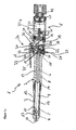
- the anesthetic syringe 1 in the FIG. 1a consists essentially of a housing 2, which receive a carpule 5 in a carpule space 3 of a cartridge case 4 and can drive out their content with a hydraulic-pneumatic drive system 6 via a feed piston 7.
- the feed piston 7 is slidably mounted in a feed cylinder 8 along a main extension axis 9 of the anesthetic syringe 1, the feed piston 7 occupies an inner end position in the figure and can be moved at a feed along the axis 9 to a stop shoulder 10, where he has an outer End position occupies.
- the feed piston 7 passes through the carpule space 3, so that liquid can be ejected from an inserted carpule 5 through a needle opening 11.
- a cannula is inserted into the needle opening 11.
- the cannula has a tip for piercing the tissue and a second tip for piercing the sealing membrane of the inserted carpule 5.
- a special receptacle for the cannula is provided (not shown in detail), so that accidentally a cannula can not be inserted into the syringe 1, which mechanically fails at the sometimes high pressures.
- the cartridge case 4 has two viewing windows 12, through which the feed position of the feed piston 7 within the cartridge case 4 is visible.
- the carpule 5 has a commercial head design 13, so that the attending physician is not limited in the choice of cartridges, which he already knew from working with conventional syringes.
- the cartridge tube 4 is fixedly connected via a bayonet closure 14 with the feed cylinder 8.
- the feed piston 7 faces a first hydraulic chamber 16, wherein a lateral surface 17 of the feed piston 7 is sealed by an O-ring 18 with respect to the first hydraulic chamber 16.
- a second hydraulic chamber 19 is provided and connected to the first hydraulic chamber 16 via a control bore 20.
- the opening of the control bore 20 between the first hydraulic chamber 16 and the second hydraulic chamber 19 controls a valve spool 21 which is slidably mounted along a direction of movement 22 and abuts on an outer side of the housing 2 to a probe arm 23 of a control button 24.
- the control button 24 Facing the front region of the syringe 1, the control button 24 has a touch surface 25 for depressing the feeler arm 23 - and thus the valve spool 21 - on.
- the feeler arm 23 is rotatably mounted on a probe bearing 26 about a stylus. The stylus is perpendicular to the main extension axis 9 of the anesthetic syringe. 1
- valve spool 21 protrudes with a pressure plate 27 into the first hydraulic chamber, while the lateral surface of the valve spool 21 is sealed with an O-ring.
- an index piston 28 is mounted in the housing 2 along a radial direction 29 to the main extension direction 9 of the syringe 1.
- the index piston 28 protrudes with a foot 30 into the first hydraulic chamber 16, while the lateral surface of the index piston 28 is sealed with an O-ring 31.
- a compression spring (not shown) presses the index piston 28 to an inner end position in which the foot 30 comes to rest on an inner boundary surface 32 (in the figure, the index piston 28 is shown extended to a stop for clarity) without pressure in the Hydraulic chamber 1, however, the index piston in the present embodiment 1 assumes the inner end position in practice).
- a further compression spring 33 presses the valve spool 21 under pretension at rest in the illustrated outer end position, which is defined by stop of the relative to the cylindrical portion of the slider 21 enlarged executed pressure plate 27 to the housing 2 at a stop 34.
- the second hydraulic chamber 19 is bounded at the rear by a separating piston 35 which is displaceably mounted along the main extension direction 9 of the syringe 1 and in turn projects rearwardly into a pressure chamber 37a, 37b and thus limits it.
- a printing plate 38 forms the essential element of the separating piston 35.
- On sides of the pressure plate 38 a double O-ring seal 39 is provided. So that the separating piston 35 does not tilt during a movement between the second hydraulic chamber 19 and the pressure chamber 37a, a guide for a cylindrical guide rod 36 of the separating piston 35 is provided in the pressure chamber 37, 37b. Large passages connect the two sub-chambers 37a and 37b of the pressure chamber (not shown in the figure).
- the pressure chamber 37 b is rearwardly bounded by a sealing plug 40 which is connected via a further O-ring 41 close to the pressure chamber 37 and with a check valve (not shown in detail) is provided, via which a gas cartridge or an adapter 42 for connecting a Compressed gas line is connected to the syringe 1.
- the necessary hydraulic pressure for advancing the feed piston 7 is generated by the pressure chamber 37.
- the separating piston 35 separates the gas volume (filled under pressure via the adapter 42 into the pressure chamber 37) by the hydraulic oil in the second hydraulic chamber 19. Via the control bore 20, the hydraulic oil under pressure can reach the valve slide 21.
- the valve spool is closed by the compression spring 33 in the idle state.
- the compression spring is biased by a threaded cover (not numbered, arranged in the housing 2 the valve spool 21 on the opposite side in its extension) to produce the necessary sealing force on the control bore 20.
- the valve is a 2/2-way poppet valve with proportional characteristics, thus, depending on the valve lift, the volume flow and thus the export speed of the feed piston 7 can be controlled.
- the feeler arm 23 preferably has to be actuated on the touch surface 25 of the housing 2 of the syringe 1. This forcibly shifts the valve spool 21 along its direction of movement 22 against the compression spring 33 into the housing 2 of the syringe 1.
- the released flow cross section can now be traversed by the hydraulic oil from the second hydraulic chamber 19 to the first hydraulic chamber 16.
- the piston head 15 of the feed piston 7 is pressurized, so that the feed piston 7 extends.
- the index piston 28 acts as a small single-acting hydraulic cylinder, on whose piston three grooves are introduced to indicate the pressure.
- the piston 28 is held by the spring at rest in the housing 2 (this state is not shown here).
- the pressure can then be read off via the grooves on the piston 28.
- the cartridge case 4 is separated via the bayonet lock from the housing 2 of the syringe 1, replaced the carpule and the cartridge case 4 then connected again via the bayonet lock with the feed cylinder 8.
- the feed piston 7 must be brought back into its inner end position.
- the syringe 1 must be inserted into a charging station and pushed back via a lever mechanism of the feed piston 7.
- the charging station actuates the feeler arm 23 and opens the valve of the control bore 20 so that a connection between the first 16 and the second hydraulic chamber 19 is established.
- the separating piston 35 moves back when pushing the feed piston 7 to the inner end position and biases the gas volume in the pressure chamber 37 back to the original pressure.
- the figure shows the filling adapter 42.
- the pressure chamber 37 can be filled with nitrogen under pressure.
- the check valve on the O-ring 41 prevents gas leakage when the adapter is unscrewed.
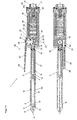
- the anesthetic syringe 1 in the FIG. 1b consists essentially of a housing 2, which receive a carpule 5 in a carpule space 3 of a cartridge case 4 and can drive out their content with a hydraulic-pneumatic drive system 6 via a feed piston 7.
- the feed piston 7 is slidably mounted in a feed cylinder 8 along a main extension axis 9 of the anesthetic syringe 1, the feed piston 7 occupies an inner end position in the figure and can be moved at a feed along the axis 9 to a stop shoulder 10, where he has an outer End position occupies.
- the feed piston 7 passes through the carpule space 3, so that liquid can be ejected from an inserted carpule 5 through a needle opening 11.
- a cannula is inserted into the needle opening 11.
- the cannula has a tip for piercing the tissue and a second tip for piercing the sealing membrane of the inserted carpule 5.
- a special receptacle for the cannula is provided (not shown in detail), so that accidentally a cannula can not be inserted into the syringe 1, which mechanically fails at the sometimes high pressures.
- the cartridge case 4 has two viewing windows 12, through which the feed position of the feed piston 7 within the cartridge case 4 is visible.
- the carpule 5 has a commercial head design 13, so that the attending physician is not limited in the choice of cartridges, which he already knew from working with conventional syringes.
- the cartridge tube 4 is fixedly connected via a bayonet closure 14 with the feed cylinder 8.
- the feed piston 7 faces a first hydraulic chamber 16, wherein a lateral surface 17 of the feed piston 7 is sealed by a Gleitdichtsystem 18 relative to the first hydraulic chamber 16.
- a second hydraulic chamber 19 is provided and connected to the first hydraulic chamber 16 via a control bore 20.
- the opening of the control bore 20 between the first hydraulic chamber 16 and the second hydraulic chamber 19 controls a valve spool 21 via a check valve 33, the valve spool 21 is slidably mounted along a direction of movement 22 and abuts on an outer side of the housing 2 to a feeler 23 of a control button 24 ,
- the control button 24 Facing the front region of the syringe 1, the control button 24 has a touch surface 25 for depressing the feeler arm 23 - and thus of the valve spool 21 - for this purpose, the feeler arm 23 is rotatably mounted on a probe bearing 26 about a stylus.
- the stylus is perpendicular to the main extension axis 9 of the anesthetic syringe.
- valve spool 21 protrudes with a pressure plate 27 into the first hydraulic chamber, while the lateral surface of the valve spool 21 is sealed with a Gleitdichtsystem.
- an index piston 28 is mounted in the housing 2 along the main extension direction 9 of the syringe 1.
- the index piston 28 protrudes with a foot 30 into the first hydraulic chamber 16, while the lateral surface of the index piston 28 is sealed with a Gleitdichtsystem 31.
- a compression spring 29 presses the index piston 28 to an inner end position, in which the foot 30 comes to rest on an inner boundary surface 32.
- a check valve 33 presses the valve spool 21 under pretension at rest in the illustrated outer end position, which is defined by stop of the opposite to the cylindrical part of the slider 21 enlarged executed pressure plate 27 to the housing 2 at a stop 34.
- the second hydraulic chamber 19 is rearwardly bounded by a gas reservoir 35, which is designed to be deformable along the main extension direction 9 of the syringe 1, and in turn forms a self-contained pressure chamber 37 and limits it.
- An accordion-like deformable metal bellows 36 along the main extension direction 9 forms the essential element of the gas reservoir 35, wherein the gas reservoir 35 is closed in the direction of the second hydraulic chamber 19 by a cover plate 38 and rearwardly with a storage cover 43, wherein a free of movable sealing elements and completely from the hydraulic oil separate pressure chamber 37 is formed.
- the gas storage 35 is connected to the storage lid 43 via an O-ring 44 close to the second hydraulic chamber 19.
- the pressure chamber 37 is rearwardly bounded by a sealing plug 40, which is connected via a further O-ring 41 close to the pressure chamber 37 and is provided with a check valve 42, via which a gas cartridge or an adapter for connecting a compressed gas line connected to the syringe 1 is.
- the necessary hydraulic pressure for advancing the feed piston 7 is generated by the pressure chamber 37.
- the gas accumulator 35 separates the gas volume (filled under pressure via the closure stuffer into the pressure chamber 37) by the hydraulic oil in the second hydraulic chamber 19.
- the hydraulic oil under pressure can reach the valve spool 21 via the control bore 20.
- the valve spool is closed by the check valve 33 in the idle state.
- the check valve 33 is arranged in the reverse direction serially to the second hydraulic chamber 19 in order to generate the necessary sealing force on the control bore 20.
- the valve is a seat valve with proportional characteristics, thus, depending on the valve lift, the volume flow and thus the export speed of the feed piston 7 can be controlled.
- the feeler arm 23 preferably has to be actuated on the touch surface 25 of the housing 2 of the syringe 1. This forcibly displaces the valve spool 21 along its direction of movement 22 against the compression spring of the check valve 33 into the housing 2 of the syringe 1.
- the released flow cross section can now be traversed by the hydraulic oil from the second hydraulic chamber 19 to the first hydraulic chamber 16.
- the piston head 15 of the feed piston 7 is pressurized, so that the feed piston 7 extends.
- the index piston 28 In addition to this pressure sensing, there is an optical pressure gauge above the index piston 28 which indicates the cylinder pressure and thus the piston force - which can be considered as a measure of the injection pressure.
- the index piston 28 acts as a small single-acting hydraulic cylinder, on whose piston three grooves are introduced to indicate the pressure. The piston 28 is held by the spring 29 in the idle state in the housing 2.
- the cartridge case 4 is separated via the bayonet lock from the housing 2 of the syringe 1, replaced the carpule and the cartridge case 4 then connected again via the bayonet lock with the feed cylinder 8.
- the feed piston 7 must be brought back into its inner end position.
- the syringe 1 must be inserted into a charging station and pushed back via a lever mechanism of the feed piston 7.
- the check valve 33 opens, wherein a connection between the first 16 and second hydraulic chamber 19 is produced.
- the gas storage 35 is compressed when pushing back the feed piston 7 and biases the gas volume in the pressure chamber 37 back to the original pressure.
- an adapter is connected to the filling plug 40.
- the pressure chamber 37 can be filled with nitrogen under pressure.
- the check valve on the O-ring 42 prevents leakage of the gas when the adapter is unscrewed.
- a sliding seal system a piston 196 and a cylinder 197 are shown.
- the sliding seal system includes the O-ring 199 and a ring 198 of PTFE, with the O-ring 199 biasing the ring of PTFE.
- the O-ring 199 expresses due to its elasticity and the concomitant restoring force the ring of PTFE 198 against a wall of the cylinder 197.
- the piston 196 can be guided in the cylinder 197 so that forming spaces are sealed to each other left and right of Gleitdichtsystem.
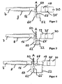
- FIG. 2 represents a variant with a check valve 65.
- the check valve 65 which is used here instead of the vertical slide 21, is used to control the syringe 1, in which the sealing body of the valve (shown here as a ball) by means of a confirmation pin or according to pins 50th moved against the spring force in the direction A and thus a control cross section is released.
- Pressure in the first hydraulic chamber 16 can now be established via the control cross section via the second hydraulic chamber 19. This is realized via the line 52 and the control element 60, which is shown separately here, since this is a commercially available component.
- the gas pressure in the gas accumulator 70 can build up pressure in the second hydraulic chamber via the separating piston 35, which actuates the feed piston 7 into the carpule chamber 3 when the control element is actuated via the second and first hydraulic chambers.
- FIG. 3 is a variant with a check valve 65 and a throttle 62, which acts as a resistive element shown.
- the throttle 62 may in this case be arranged both before (as shown here) and after the check valve 65.
- a diaphragm can also be used as a resistance element.
- These elements can also be designed so that the operator changes the resistance element. This can be realized in particular by a set screw, which narrows the supply line 60.
- FIG. 4 a variant with two check valves and a throttle 62 is shown.
- the second check valve 68 which takes over the function of the second control here, connected to the first and second hydraulic chamber and thus realized a parallel connection of the second control element 68 and first control 65 with the series connected to the first control element 65 choke 62nd
- FIGS. 5 to 7 Three possibilities of operation for opening the check valve and for force feedback for the operator are shown.
- the pin 52 a circumferential annular surface 53, which is designed as an active surface
- the switching element comprises a pin 52 with active surface 53 and a check valve 65, wherein the pin is guided by the guide means 58 substantially.
- the switching element can be moved or switched by pressing in direction A via the lever 110, which rotates about the fulcrum or according to the lever axis 100.
- FIG. 6 is an effective area shown spatially separated from the first pin 52a.
- the switching element comprises the first pin 52 a, which can act on the check valve 65, and the second pin 52 b, which experiences the force feedback via the first hydraulic chamber 16, and the lever 110, which is guided around the fulcrum (lever axis) 100.
- the force required on the actuating pin is of the same order of magnitude as the return force, but should not be felt by the user, as it affects the haptic perception of the effective pressure. Therefore, the actuator is placed close to the lever axes.
- the second pin 52b is further away from the fulcrum (lever axis) 100 than the first pin 52a.
- Both pin 52a and pin 52b are actuated by a common lever (arm) 110.
- the lever 110 When the lever 110 is actuated, the hydraulic fluid flows into the first hydraulic chamber 16 so that the pressure which arises in the hydraulic chamber is transmitted to the second pin 52b. This force is transmitted to the lever 110 to the operator.
- FIG. 7 Two separate but coaxial return surfaces are shown with a lever system.
- the right part of the figure represents the viewing direction AA.
- the inner pin 52 is used to open the check valve (not shown), the annular surface 53 is used for pressure-dependent force feedback.
- the actuation of the pin 52 is done by means of a first lever 110, 100 which is coupled to the second lever 210, 220.
- the lever axes are each mounted stationary in the housing.
- FIGS. 8 and 9 show realizations of resistance elements. On the left side L is the unused check valve and on the right side R the connected check valve is shown.
- FIG. 8 a resistance element with constant resistance is shown.
- a gap 310 located between the actuating pin 52 and the check valve housing 300 serves to throttle. By operating the pin 52, the length and height of the throttle gap 310 is not changed. The throttle effect is thus constant over the stroke.
- FIG. 9 shows a variable position choke above the hub which results in a change in resistance. Left and right again differentiates the switching element in the actuated and non-actuated state.
- the length of the throttle gap which is realized by the narrowing cross-section of the pin, there is a stroke-dependent throttle effect, which can be used for dosing.
- a non-constant resistance is realized.
- FIG. 10 is the gas storage 70, which is separated via an O-ring 400 from the filling nozzle 2000, shown.
- the gas storage 70 acts as a first space 1000 and the filling nozzle as a second space 2000. If, for example, a gas cartridge is flanged to the filling nozzle, the pressure in the second chamber 2000 may exceed the pressure in the first chamber 1000, while the elastic element 400, which is designed here as an O-ring, expands and the pressure in the first chamber 1000 increases at.
- the equivalent circuit 420 is shown as a check valve on the right.
- a device is provided, as shown in sectional view in FIG. 11 is shown.
- the transition from the gas chamber 70 to the second hydraulic chamber 19, which has an oil, is shown.
- the seals 510 each seal the systems to each other via the piston 35.
- the stroke of the piston is designated here by S.
- a cavity (gap) 530 is formed between the piston and the boundary 520. This space has an opening 540 to the environment. Through this opening, a degassing of the gas, which passed through the seal in the gap, can be realized.
Landscapes
- Health & Medical Sciences (AREA)
- Vascular Medicine (AREA)
- Engineering & Computer Science (AREA)
- Anesthesiology (AREA)
- Biomedical Technology (AREA)
- Heart & Thoracic Surgery (AREA)
- Hematology (AREA)
- Life Sciences & Earth Sciences (AREA)
- Animal Behavior & Ethology (AREA)
- General Health & Medical Sciences (AREA)
- Public Health (AREA)
- Veterinary Medicine (AREA)
- Physics & Mathematics (AREA)
- Fluid Mechanics (AREA)
- Infusion, Injection, And Reservoir Apparatuses (AREA)
Description
- Die Erfindung betrifft eine Spritze, insbesondere eine Anästhesiespritze mit einem längsverschieblichen Vorschubkolben, welcher über eine erste Hydraulikkammer verschiebbar angeordnet ist und einer zweiten Hydraulikkammer, wobei die erste und zweite Hydraulikkammer widerstandsregulierbar über ein erstes Steuerelement verbunden sind, wobei das erste Steuerelement über ein Schaltelement betätigbar ist und das Schaltelement ein Betätigungsstift ist..
- In vielen Bereichen der Medizin stellt sich regelmäßig die Aufgabe, Anästhesiemittel in einen menschlichen oder tierischen Körper zu injizieren. Hierzu werden Anästhesiespritzen verwendet, die sich auch im Wesentlichen bewährt haben.
- Der weit überwiegende Teil der in der Praxis verwendeten Anästhesiespritzen ist manuell zu bedienen. Diese Art der Anästhesiespritzen bedarf aufgrund Ihrer allgemeinen Bekanntheit keiner Erläuterung.
- In der
WO 2005/075009 A1 wird eine sehr handliche Anästhesiespritze zur Verfügung gestellt, wodurch Injektionsvorgänge präzise und wiederholbar durchführbar sind. Diese Anästhesiespritze weist eine erste und eine zweite Hydraulikkammer auf, welche über einen der Vertikalschieber widerstandsregulierbar oder entsprechend steuerbar verbunden sind. Um nach einem Einspritzvorgang die Anästhesiespritze wieder in die Ausgangsposition zu bringen, muss dieser Vertikalschieber manuell oder entsprechend mit Kraftaufwand in seine Ursprungsposition gebracht werden. - Eine gattungsgemäße Spritze ist aus der
WO 02/49697 A1 - Aufgabe der Erfindung ist es, über nur eine Verbindung der Hydraulikkammerneinen bidirektionalen Flüssigkeitsaustausch zu ermöglichen. Durch Einsparung von Bauteilen soll die Spritze kompakter gestaltet werden.
- Gelöst wird diese Aufgabe durch eine Spritze, mit den Merkmalen des Patentanspruchs 1. Über den Vorschubkolben kann ein Medikament in einem Karpulenraum über eine angebrachte Injektionsnadel in ein Gewebe eingebracht werden.
- Dadurch kann vorteilhafterweise die Rückstellung der Spritze ohne Betätigung eines Auslösehebels erfolgen, da das Rückschlagventil selbständig öffnet und die Hydraulikflüssigkeit somit von der ersten Hydraulikkammer in die zweite Hydraulikkammer befördert werden kann.
- Rückschlagventile der hier genannten Art können insbesondere Standardrückschlagventile umfassen, welche als Fertigbauteile erwerbbar sind. Dadurch kann vorteilhafterweise der Herstellungspreis für eine solche Spritze reduziert werden.
- In einer Ausprägungsform der Erfindung kann zwischen erster und zweiter Hydraulikkammer ein Widerstandselement in Reihe zum ersten Rückschlagventil geschaltet sein und somit insbesondere das erste Steuerelement, ein erstes Rückschlagventil und ein Widerstandselement umfassen. Dadurch kann vorteilhafterweise ein Widerstand eingestellt werden, wodurch die Injektion homogener und für den Patienten angenehmer verläuft.
- Das Widerstandselement kann als Drossel oder Blende ausgestaltet sein.
- Um den Vorschubkolben bei enthaltenem Widerstandselement nach Abschnitt 9 möglichst mit wenig Kraftaufwand wieder in die ursprüngliche Position nach einem Injektionsvorgang zu bringen, kann zwischen erster und zweiter Hydraulikkammer ein zweites Steuerelement, insbesondere ein zweites Rückschlagventil parallel zum ersten Steuerelement geschaltet sein. Dadurch kann, bei manueller Betätigung des Vorschubkolbens, die Hydraulikflüssigkeit aus der ersten Hydraulikkammer über das zweite Steuerelement in die zweite Hydraulikkammer fließen, ohne dass dabei der erhöhte Durchflusswiderstand des ersten Steuerelements spürbar wird.
- In einer Ausgestaltungsform der Erfindung kann das Schaltelement als Pin oder entsprechend als ein Betätigungsstift ausgestaltet sein, welcher verschiebbar ist und bei Betätigung das erste Steuerelement öffnet, so dass die erste und zweite Hydraulikkammer mit einander leitend verbunden sind. Somit kann vorteilhafterweise eine einfache Betätigung des Steuerelements erfolgen.
- Damit die, die Spritze betätigende Person ein Gefühl über den Druck in der Karpule erhält, kann das Schaltelement eine Wirkfläche aufweisen, welche wenigstens einen Teil des in der Spritze wirkenden hydraulischen Drucks und somit einer wirkenden Kraft mittels des Stellelements an den Benutzer überträgt.
- In einer weiteren Ausprägungsform der Erfindung kann die wirkende Kraft verstärkt werden. Dies kann insbesondere dann vorteilhaft sein, wenn zum Betätigen des Steuerelements eine Kraft ausreicht, welche die betätigende Person kaum fühlt, jedoch die dann wirkende Kraft über die Wirkfläche haptisch erfasst. Um diese Kraft über ein Schaltsystem an dem Benutzer rückzukoppeln, kann vorteilhafterweise die Verstärkung der wirkenden Kraft über einen weiteren Pin mit einer Kraftwirkung über einen Hebel realisiert werden.
- In einer weiteren Ausprägungsform der Erfindung kann die Verstärkung der Kraft über ein Hebelsystem, von zwei miteinander verschaltenden Hebeln erfolgen. Dabei ist der Hebelarm, welcher den Pin für das Stellelement betätigt nahe am Hebelpunkt oder entsprechend Hebelachse des zweiten Hebels verortet. Idealerweise wird der zweite Hebel am Ende des zweiten Hebelarms betätigt.
- Um ein Widerstandselement zu realisieren kann das Widerstandselement als Spalt mit einer Spaltlänge um das Schaltelement, insbesondere um den Pin, ausgestaltet sein. Dabei umfließt die Hydraulikflüssigkeit den Pin entlang des Spaltes, welcher als Widerstand für die Hydraulikflüssigkeit, welche von der zweiten Hydraulikkammer in die erste Hydraulikkammer fließt, wirkt.
- In einer weiteren Ausprägungsform der Erfindung kann die Spaltlänge so ausgestaltet sein, dass sich die Spaltlänge beim Betätigen des Schaltelements verändert. Dadurch kann vorteilhafterweise ein nichtkonstanter Widerstand realisiert werden.
- Um einen Gasraum zu befüllen, welcher insbesondere zur Bereitstellung der Energie in der Spritze dient, kann die Spritze einen Gasraum umfassen, welcher über einen beweglichen Trennkolben oder eine Membrane mit der zweiten Hydraulikkammer verbunden ist, wobei dieser Gasraum über einen Befüllstutzen befüllbar ist, wobei der Gasraum über einen O-Ring gegenüber dem Befüllstutzen abgedichtet ist, wobei der O-Ring so ausgestaltet ist, dass die Funktion eines Rückschlagventils ausgeprägt wird. Durch diese Ausgestaltungsform kann vorteilhafterweise eine einfache Befüllung des Gasraums realisiert werden, wobei nach der Befüllung der Gasraum im Wesentlichen hermetisch abgedichtet ist.
- Sowohl der hier aufgeführte O-Ring als auch sämtliche weiteren in diesem Dokument aufgeführten O-Ringe können Dichtungen, welche insbesondere als Ringe ausgestaltet sind, vorspannen und somit ein Gleitdichtsystem aus O-Ring und gespannter Dichtung bilden.
- Um ein Begasen der Hydraulikflüssigkeit in der zweiten Hydraulikkammer zu verhindern, kann der Trennkolben zwei Dichtelemente, welche je den Gasraum und die zweite Hydraulikkammer abdichten, einen Kolbensystem ausbilden, wobei das Kolbensystem entlang eines Begrenzungselements führbar ist, wobei die Dichtungselemente, der Trennkolben und das Begrenzungssystem einen Hohlraum ausbilden, welcher eine Öffnung zur Umgebung aufweist.
- Vorteilhafterweise ist die Spritze so ausgestaltet, dass die Öffnung in allen Trennkolbenpositionen austauschenden Kontakt zwischen Hohlraum und Umgebung ausbildet. Dadurch kann vorteilhafterweise das Begasen der Hydraulikflüssigkeit über alle Kolbenpositionen verhindert werden.
- In einer weiteren Ausprägungsform der Erfindung kann die zweite Hydraulikkammer vollständig durch einen eigenständigen in sich vollständig geschlossenen Gasspeicher, der mit der zweiten Hydraulikkammer verbunden ist, separiert werden, wodurch vorteilhafterweise ein begasen der zweiten Hydraulikkammer verhindert werden kann.
- Der eigenständige, in sich vollständig geschlossenen Gasspeicher kann als faltbares Kolbenelement ausgeführt sein, wobei das Kolbenelement entlang der Hauptbewegungsachse der Spritze stark deformierbar und radial kaum deformierbar ist, wobei das Kolbenelement über einen Befüllstutzen befüllbar ist, wobei der Gasraum im inneren des Kolbenelementes über einen O-Ring gegenüber dem Befüllstutzen abgedichtet ist, wobei der O-Ring so ausgestaltet ist, dass die Funktion eines Rückschlagventils ausgeprägt wird. Durch diese Ausgestaltungsform kann vorteilhafterweise eine einfache Befüllung des Gasraums realisiert werden, wobei nach der Befüllung der Gasraum im Wesentlichen hermetisch abgedichtet ist.
- Dieser O-Ring kann insbesondere so weitergebildet werden, dass mit diesem ein Gleitdichtsystem gebildet wird, welches an die Position des O-Rings tritt.
- Faltbare Kolbenelemente der hier genannten Art können insbesondere Federmembranspeicher umfassen, welche als Fertigbauteile erwerbbar sind.
- Zur bedarfsweisen Entlüftung des vollständig geschlossenen Gasspeichers kann eine verschließbare Entlüftungsöffnung integriert sein, wobei die Entlüftung dergestallt ausgeführt ist, dass die Entlüftung des Gastraums vorteilshafterweise vor der Trennung des Gasspeichers von der zweiten Hydraulikkammer erfolgt. Durch diese Ausgestaltungsform kann vorteilshafterweise eine gefahrlose Trennung des Gasspeichers von der zweiten Hydraulikkammer realisiert werden.
- In einem weiteren Aspekt der Erfindung kann ein Rückschlagventil realisiert werden, wobei das Rückschlagventil eine Durchlass- und Sperrrichtung ausbildet, wobei das Rückschlagventil einen ersten mit einem zweiten Raum verbindet, wobei das Rückschlagventil mittels O-Ring ausgeführt ist, welcher eine Nut umschließt. Dabei weist die Nut eine Verbindung zum ersten Raum auf und der O-Ring ist im Wesentlichem im zweiten Raum verortet. Somit dichtet der O-Ring den zweiten vom ersten Raum ab, sofern der zweite Raum einen höheren Druck als der erste Raum aufweist. Für den Fall, dass der erste Raum einen höheren Druck als der zweite Raum aufweist, dehnt sich der O-Ring aus und eine leitende Verbindung vom ersten zum zweiten Raum wird ausgebildet. Dadurch kann ein Medium vom ersten in den zweiten Raum geleitet werden.
- Dieser hier aufgeführte O-Ring kann ebenfalls insbesondere so weitergebildet werden, dass mit diesem ein Gleitdichtsystem gebildet wird, welches an die Position des O-Rings tritt.
- O-Ringe und Gleitdichtsysteme der hier genannten Art können sämtliche Dichtelemente umfassen, welche aufgrund ihrer Elastizität einen Raum von einem anderen abdichten, wobei die gespannten Ringe der Gleitdichtsysteme PTFE, KFM und FFKM umfassen können. Insbesondere die Materialien KFM (Fluorkautschuk) und FFKM können in Systemen eingesetzt werden, in denen die vorgespannten Ringe einer aggressiven chemischen Umgebung ausgesetzt sind. Insbesondere können die vorgespannten Ringe der Firma Trellborg eingesetzt werden, die unter den registrierten Markennamen, Turcon, Stepseal 2K und/oder Zurcon geführt werden.
- In einer Ausprägungsform der Erfindung kann der O-Ring in Durchlassrichtung radial nach Außen dehnbar ausgestaltet sein und in Sperrrichtung die Funktion des Abdichtens erfüllen. Dadurch können vorteilhafterweise Standard- O-Ringe wie sie im Handel erhältlich sind, eingesetzt werden.
- In einem weiteren Aspekt der Erfindung wird ein O-Ring als Rückschlagventil verwendet.
- Im weiterem wird die Erfindung anhand von Ausführungsbeispielen erläutert.
- Dabei zeigt
- Figur 1a
- eine Anästhesiespritze mit einer seriellen Anordnung aus Karpulenraum, Vorschubkolben, erster Hydraulikkammer, zweiter Hydraulikkammer, Trennkolben und Druckraum,
- Figur 1b
- eine Anästhesiespritze mit einer seriellen Anordnung aus Karpulenraum, Vorschubkolben, erster Hydraulikkammer, zweiter Hydraulikkammer und Gasraum, wobei im Gasraum ein Membranbalg angeordnet ist,
- Figur 1c
- ein Gleitsystem, bei dem ein O-Ring einen PTFE-Ring vorspannt.
- Figur 2
- eine erfindungsgemäße Spritze mit erstem ond zweiten Hydraulikraum, welche über ein Rückschlagventil verbunden sind,
- Figur 3
- eine erfindungsgemäße Spritze mit ersten und zweiten Hydraulikraum, welche über ein Rückschlagventil verbunden sind, wobei zwischen Rückschlagventil und zweitem Hydraulikraum ein Widerstandselement angeordnet ist,
- Figur 4
- die Spritze aus
Figur 3 , welche um ein zweites Steuerelement erweitert ist, - Figur 5
- einen Pin mit Wirkfläche, welcher das Steuerelement über einen Hebel beschaltet,
- Figur 6
- ein System bei dem die wirkenden Kräfte verstärkt werden,
- Figur 7
- ein Hebelsystem von zwei miteinander verschaltenden Hebeln,
- Figur 8
- ein Schaltelement mit einem Spalt und einer Spaltlänge über den gesamten Steuerbereich,
- Figur 9
- eine Spaltlänge, welche sich beim Betätigen des Schaltelements verändert,
- Figur 10
- einen O-Ring als Rückschlagventil und das dazugehörge Ersatzschaltbild,
- Figur 11
- eine Entgasungsvorrichtung in der Spritze.
- Die Anästhesiespritze 1 in der
Figur 1a besteht im Wesentlichen aus einem Gehäuse 2, welches in einem Karpulenraum 3 einer Karpulenhülse 4 eine Karpule 5 aufnehmen und deren Inhalt mit einem hydraulisch-pneumatischen Antriebssystem 6 über einen Vorschubkolben 7 austreiben kann. - Der Vorschubkolben 7 ist in einem Vorschubzylinder 8 entlang einer Haupterstreckungsachse 9 der Anästhesiespritze 1 verschiebbar gelagert, wobei der Vorschubkolben 7 in der Figur eine innere Endlage einnimmt und bei einem Vorschub entlang der Achse 9 bis zu einer Anschlagschulter 10 bewegt werden kann, wo er eine äußere Endlage einnimmt. Beim Vorschub durchfährt der Vorschubkolben 7 den Karpulenraum 3, so dass Flüssigkeit aus einer eingelegten Karpule 5 durch eine Nadelöffnung 11 ausgespritzt werden kann. Zum Einsatz der Spritze 1 wird in die Nadelöffnung 11 eine Kanüle eingesetzt. Die Kanüle hat eine Spitze zum Einstechen ins Gewebe und eine zweite Spitze zum Einstechen in die Dichtmembran der eingelegten Karpule 5.
- In der Nadelöffnung 11 ist eine Spezialaufnahme für die Kanüle vorgesehen, (nicht im Detail dargestellt), damit nicht versehentlich eine Kanüle in die Spritze 1 eingesetzt werden kann, welche bei den mitunter hohen Drücken mechanisch versagt.
- Die Karpulenhülse 4 hat zwei Sichtfenster 12, durch welche die Vorschubposition des Vorschubkolbens 7 innerhalb der Karpulenhülse 4 einsehbar ist. Die Karpule 5 hat eine handelsübliche Kopfgestaltung 13, so dass der behandelnde Arzt nicht in der Wahl der Karpulen eingeschränkt wird, welche er bereits von der Arbeit mit herkömmlichen Spritzen kannte. Die Karpulenhülse 4 ist über einen Bajonettverschluss 14 mit dem Vorschubzylinder 8 fest verbunden.
- Mit einer Druckplatte 15 ist der Vorschubkolben 7 einer ersten Hydraulikkammer 16 zugewandt, wobei eine Mantelfläche 17 des Vorschubkolbens 7 über einen O-Ring 18 gegenüber der ersten Hydraulikkammer 16 abgedichtet ist.
- Rückwärtig der ersten Hydraulikkammer 16 ist eine zweite Hydraulikkammer 19 vorgesehen und mit der ersten Hydraulikkammer 16 über eine Steuerbohrung 20 verbunden. Die Öffnung der Steuerbohrung 20 zwischen der ersten Hydraulikkammer 16 und der zweiten Hydraulikkammer 19 regelt ein Ventilschieber 21, welcher entlang einer Bewegungsrichtung 22 verschiebbar gelagert ist und an einer Außenseite des Gehäuses 2 an einen Tasterarm 23 eines Steuertasters 24 stößt. Dem vorderen Bereich der Spritze 1 zugewandt weist der Steuertaster 24 eine Tastfläche 25 zum Niederdrücken des Tasterarms 23 - und somit des Ventilschiebers 21 - auf. Hierzu ist der Tasterarm 23 an einem Tasterlager 26 um einen Tasterbolzen drehbar gelagert. Der Tasterbolzen liegt senkrecht zur Haupterstreckungsachse 9 der Anästhesiespritze 1.
- Der Ventilschieber 21 ragt mit einer Druckplatte 27 in die erste Hydraulikkammer hinein, während die Mantelfläche des Ventilschiebers 21 mit einem O-Ring abgedichtet ist.
- In ähnlicher Weise ist ein Indexkolben 28 im Gehäuse 2. entlang einer zur Haupterstreckungsrichtung 9 der Spritze 1 radialen Richtung 29 gelagert. Der Indexkolben 28 ragt mit einem Fuß 30 in die erste Hydraulikkammer 16 hinein, während die Mantelfläche des Indexkolbens 28 mit einem O-Ring 31 abgedichtet ist. Eine Druckfeder (nicht dargestellt) presst den Indexkolben 28 zu einer inneren Endlage, bei welcher der Fuß 30 an einer inneren Begrenzungsfläche 32 zum Liegen kommt (in der Figur ist der Indexkolben 28 zur besseren Übersichtlichkeit bis zu einem Anschlag ausgefahren dargestellt; ohne Druck in der Hydraulikkammer 1 nimmt der Indexkolben bei der vorliegenden Ausführung 1 jedoch in der Praxis die innere Endposition ein).
- Eine weitere Druckfeder 33 presst den Ventilschieber 21 unter Vorspannung im Ruhezustand in die dargestellte äußere Endlage, welche durch Anschlag der gegenüber dem zylindrischen Teil des Schiebers 21 vergrößert ausgeführten Druckplatte 27 an das Gehäuse 2 an einem Anschlag 34 definiert wird.
- Die zweite Hydraulikkammer 19 ist rückwärtig von einem Trennkolben 35 begrenzt, welcher entlang der Haupterstreckungsrichtung 9 der Spritze 1 verschiebbar gelagert ist und seinerseits rückwärtig in einen Druckraum 37a, 37b ragt und diesen somit begrenzt. Eine Druckplatte 38 bildet das wesentliche Element des Trennkolbens 35. An Seiten der Druckplatte 38 ist eine Doppel-O-Ring-Dichtung 39 vorgesehen. Damit der Trennkolben 35 bei einer Bewegung zwischen der zweiten Hydraulikkammer 19 und dem Druckraum 37a nicht verkantet, ist im Druckraum 37, 37b eine Führung für einen zylindrischen Führungsstab 36 des Trennkolbens 35 vorgesehen. Große Durchlässe verbinden die beiden Teilkammern 37a und 37b des Druckraums (in der Figur nicht dargestellt).
- Der Druckraum 37b wird rückwärtig durch einen Verschlussstopfen 40 begrenzt, welcher über einen weiteren O-Ring 41 dicht an den Druckraum 37 angeschlossen ist und mit einem Rückschlagventil (nicht im Detail dargestellt) versehen ist, über welches eine Gaspatrone oder ein Adapter 42 zum Anschluss einer Druckgasleitung mit der Spritze 1 verbunden ist.
- Im Betrieb wird der notwendige Hydraulikdruck zum Vorschub des Vorschubkolbens 7 vom Druckraum 37 erzeugt. Der Trennkolben 35 trennt dabei das Gasvolumen (unter Druck über den Adapter 42 in den Druckraum 37 gefüllt) vom Hydrauliköl in der zweiten Hydraulikkammer 19. Über die Steuerbohrung 20 kann das unter Druck stehende Hydrauliköl zum Ventilschieber 21 gelangen. Der Ventilschieber wird über die Druckfeder 33 im Ruhezustand verschlossen. Die Druckfeder ist über einen Gewindedeckel (nicht beziffert, im Gehäuse 2 dem Ventilschieber 21 auf der gegenüberliegenden Seite in dessen Verlängerung angeordnet) vorgespannt, um die notwendige Dichtkraft an der Steuerbohrung 20 zu erzeugen. Das Ventil ist ein 2/2-Wege-Sitzventil mit proportionaler Charakteristik, somit kann abhängig vom Ventilhub der Volumenstrom und damit die Ausfuhrgeschwindigkeit des Vorschubkolbens 7 gesteuert werden.
- Um den Vorschubkolben 7 auszufahren, muss der Tasterarm 23 bevorzugt an dessen Tastfläche 25 zum Gehäuse 2 der Spritze 1 hin betätigt werden. Dies verschiebt zwangsweise den Ventilschieber 21 entlang seiner Bewegungsrichtung 22 gegen die Druckfeder 33 in das Gehäuse 2 der Spritze 1 hinein. Der freigegebene Strömungsquerschnitt kann nun vom Hydrauliköl von der zweiten Hydraulikkammer 19 zur ersten Hydraulikkammer 16 hin durchflossen werden. Somit wird der Kolbenboden 15 des Vorschubkolbens 7 mit Druck beaufschlagt, so dass der Vorschubkolben 7 ausfährt.
- Liegt über das Gewebe, in welches die Spritze 1 eingestochen ist, eine Gegenkraft am Vorschubkolben 7 an, so steigt der Druck in beiden Hydraulikkammern, auf Grund der hydraulischen Verluste an der Steuerbohrung 20 jedoch insbesondere in der ersten Hydraulikkammer 16. Dieser Druck wirkt auf den Fuß 27 des Ventilschiebers 21 in Schließrichtung des Ventils. Der behandelnde Arzt spürt über den Taster 24 den veränderten Druck und muss entsprechend stärker auf den Taster 24 drücken, damit der Ventilschieber 21 in der geöffneten Position und damit das Ventil der Steuerbohrung 20 geöffnet bleibt.
- Zusätzlich zu dieser Drucksensierung ist eine optische Druckanzeige über den Indexkolben 28 vorhanden, die den Zylinderdruck und damit die Kolbenkraft - welche als Maß für den Injektionsdruck angesehen werden kann - anzeigt. Dabei fungiert der Indexkolben 28 als kleiner einfachwirkender Hydraulikzylinder, an dessen Kolben drei Nuten zur Anzeige der Druckstärke eingebracht sind. Der Kolben 28 wird von der Feder im Ruhezustand im Gehäuse 2 gehalten (dieser Zustand ist hier nicht dargestellt). Bei ansteigendem Hydraulikdruck in der ersten Hydraulikkammer entsteht über den Fuß 30 des Indexkolbens 28 eine Kraft, welche der Federvorspannung entgegenwirkt und den Indexkolben 28 entsprechend der hydraulischen Druckverhältnisse in der ersten Hydraulikkammer 16 entlang der Bewegungsrichtung 29 aus dem Gehäuse 2 der Spritze 1 mehr oder weniger weit ausfährt. Über die Nuten am Kolben 28 kann dann der Druck abgelesen werden.
- Ist der Vorschubkolben 7 komplett ausgefahren und somit die Glaskarpule 5 entleert, muss für die nächste Behandlung eine neue Glaskarpule in die Karpulenhülse 4 eingelegt werden. Dazu wird die Karpulenhülse 4 über den Bajonettverschluss vom Gehäuse 2 der Spritze 1 getrennt, die Karpule ausgewechselt und die Karpulenhülse 4 anschließend wieder über den Bajonettverschluss mit dem Vorschubzylinder 8 verbunden.
- Zusätzlich muss der Vorschubkolben 7 wieder in seine innere Endposition gebracht werden. Dazu muss die Spritze 1 in eine Ladestation eingelegt werden und über einen Hebelmechanismus der Vorschubkolben 7 zurückgeschoben werden. Hierzu betätigt die Ladestation den Tasterarm 23 und öffnet das Ventil der Steuerbohrung 20, damit eine Verbindung zwischen der ersten 16 und der zweiten Hydraulikkammer 19 hergestellt wird. Der Trennkolben 35 bewegt sich beim Rückschieben des Vorschubkolbens 7 zur inneren Endposition zurück und spannt das Gasvolumen im Druckraum 37 wieder auf den ursprünglichen Druck.
- Zum nach mehrfachem Gebrauch eventuell notwendigen Nachfüllen oder auch zum Erstbefüllen der Spritze mit dem Federgas zeigt die Figur den Fülladapter 42. Über diesen kann der Druckraum 37 mit Stickstoff unter Druck befüllt werden. Das Rückschlagventil am O-Ring 41 verhindert dabei ein Ausströmen des Gases, wenn der Adapter abgeschraubt wird.
- Die weitere Nummerierung bezieht sich auf das Ausführungsbeispiel der
Figur 1b . - Die Anästhesiespritze 1 in der
Figur 1b besteht im Wesentlichen aus einem Gehäuse 2, welches in einem Karpulenraum 3 einer Karpulenhülse 4 eine Karpule 5 aufnehmen und deren Inhalt mit einem hydraulisch-pneumatischen Antriebssystem 6 über einen Vorschubkolben 7 austreiben kann. - Der Vorschubkolben 7 ist in einem Vorschubzylinder 8 entlang einer Haupterstreckungsachse 9 der Anästhesiespritze 1 verschiebbar gelagert, wobei der Vorschubkolben 7 in der Figur eine innere Endlage einnimmt und bei einem Vorschub entlang der Achse 9 bis zu einer Anschlagschulter 10 bewegt werden kann, wo er eine äußere Endlage einnimmt. Beim Vorschub durchfährt der Vorschubkolben 7 den Karpulenraum 3, so dass Flüssigkeit aus einer eingelegten Karpule 5 durch eine Nadelöffnung 11 ausgespritzt werden kann. Zum Einsatz der Spritze 1 wird in die Nadelöffnung 11 eine Kanüle eingesetzt. Die Kanüle hat eine Spitze zum Einstechen ins Gewebe und eine zweite Spitze zum Einstechen in die Dichtmembran der eingelegten Karpule 5.
- In der Nadelöffnung 11 ist eine Spezialaufnahme für die Kanüle vorgesehen, (nicht im Detail dargestellt), damit nicht versehentlich eine Kanüle in die Spritze 1 eingesetzt werden kann, welche bei den mitunter hohen Drücken mechanisch versagt.
- Die Karpulenhülse 4 hat zwei Sichtfenster 12, durch welche die Vorschubposition des Vorschubkolbens 7 innerhalb der Karpulenhülse 4 einsehbar ist. Die Karpule 5 hat eine handelsübliche Kopfgestaltung 13, so dass der behandelnde Arzt nicht in der Wahl der Karpulen eingeschränkt wird, welche er bereits von der Arbeit mit herkömmlichen Spritzen kannte. Die Karpulenhülse 4 ist über einen Bajonettverschluss 14 mit dem Vorschubzylinder 8 fest verbunden.
- Mit einer Druckplatte 15 ist der Vorschubkolben 7 einer ersten Hydraulikkammer 16 zugewandt, wobei eine Mantelfläche 17 des Vorschubkolbens 7 über ein Gleitdichtsystem 18 gegenüber der ersten Hydraulikkammer 16 abgedichtet ist.
- Rückwärtig der ersten Hydraulikkammer 16 ist eine zweite Hydraulikkammer 19 vorgesehen und mit der ersten Hydraulikkammer 16 über eine Steuerbohrung 20 verbunden. Die Öffnung der Steuerbohrung 20 zwischen der ersten Hydraulikkammer 16 und der zweiten Hydraulikkammer 19 regelt ein Ventilschieber 21 über ein Rückschlagventil 33, wobei der Ventilschieber 21 entlang einer Bewegungsrichtung 22 verschiebbar gelagert ist und an einer Außenseite des Gehäuses 2 an einen Tasterarm 23 eines Steuertasters 24 stößt.
- Dem vorderen Bereich der Spritze 1 zugewandt weist der Steuertaster 24 eine Tastfläche 25 zum Niederdrücken des Tasterarms 23 - und somit des Ventilschiebers 21 - auf Hierzu ist der Tasterarm 23 an einem Tasterlager 26 um einen Tasterbolzen drehbar gelagert. Der Tasterbolzen liegt senkrecht zur Haupterstreckungsachse 9 der Anästhesiespritze 1.
- Der Ventilschieber 21 ragt mit einer Druckplatte 27 in die erste Hydraulikkammer hinein, während die Mantelfläche des Ventilschiebers 21 mit einem Gleitdichtsystem abgedichtet ist.
- In ähnlicher Weise ist ein Indexkolben 28 im Gehäuse 2 entlang der Haupterstreckungsrichtung 9 der Spritze 1 gelagert. Der Indexkolben 28 ragt mit einem Fuß 30 in die erste Hydraulikkammer 16 hinein, während die Mantelfläche des Indexkolbens 28 mit einem Gleitdichtsystem 31 abgedichtet ist. Eine Druckfeder 29 presst den Indexkolben 28 zu einer inneren Endlage, bei welcher der Fuß 30 an einer inneren Begrenzungsfläche 32 zum Liegen kommt.
- Ein Rückschlagventil 33 presst den Ventilschieber 21 unter Vorspannung im Ruhezustand in die dargestellte äußere Endlage, welche durch Anschlag der gegenüber dem zylindrischen Teil des Schiebers 21 vergrößert ausgeführten Druckplatte 27 an das Gehäuse 2 an einem Anschlag 34 definiert wird.
- Die zweite Hydraulikkammer 19 ist rückwärtig von einem Gasspeicher 35 begrenzt, welcher entlang der Haupterstreckungsrichtung 9 der Spritze 1 deformierbar ausgeführt ist, und seinerseits einen in sich abgeschlossenen Druckraum 37 bildet und diesen damit begrenzt. Ein entlang der Haupterstreckungsrichtung 9 ziehharmonikaartig deformierbarer Metallbalg 36 bildet das wesentliche Element des Gasspeichers 35, wobei der Gasspeicher 35 in Richtung der zweiten Hydraulikkammer 19 durch eine Abdeckplatte 38 und rückwärtig mit einem Speicherdeckel 43 abgeschlossen wird, wobei ein frei von beweglichen Dichtelementen und vollständig vom Hydrauliköl getrennter Druckraum 37 gebildet wird. Der Gasspeicher 35 wird mit dem Speicherdeckel 43 über einen O-Ring 44 dicht an die zweite Hydraulikkammer 19 angeschlossen.
- Der Druckraum 37 wird rückwärtig durch einen Verschlussstopfen 40 begrenzt, welcher über einen weiteren O-Ring 41 dicht an den Druckraum 37 angeschlossen ist und mit einem Rückschlagventil 42 versehen ist, über welches eine Gaspatrone oder ein Adapter zum Anschluss einer Druckgasleitung mit der Spritze 1 verbunden ist.
- Im Betrieb wird der notwendige Hydraulikdruck zum Vorschub des Vorschubkolbens 7 vom Druckraum 37 erzeugt. Der Gasspeicher 35 trennt dabei das Gasvolumen (unter Druck über den Verschlussstopfer in den Druckraum 37 gefüllt) vom Hydrauliköl in der zweiten Hydraulikkammer 19. Über die Steuerbohrung 20 kann das unter Druck stehende Hydrauliköl zum Ventilschieber 21 gelangen. Der Ventilschieber wird über das Rückschlagventil 33 im Ruhezustand verschlossen. Das Rückschlagventil 33 ist in Sperrrichtung seriell zur zweiten Hydraulikkammer 19 angeordnet, um die notwendige Dichtkraft an der Steuerbohrung 20 zu erzeugen. Das Ventil ist ein Sitzventil mit proportionaler Charakteristik, somit kann abhängig vom Ventilhub der Volumenstrom und damit die Ausfuhrgeschwindigkeit des Vorschubkolbens 7 gesteuert werden.
- Um den Vorschubkolben 7 auszufahren, muss der Tasterarm 23 bevorzugt an dessen Tastfläche 25 zum Gehäuse 2 der Spritze 1 hin betätigt werden. Dies verschiebt zwangsweise den Ventilschieber 21 entlang seiner Bewegungsrichtung 22 gegen die Druckfeder des Rückschlagventils 33 in das Gehäuse 2 der Spritze 1 hinein. Der freigegebene Strömungsquerschnitt kann nun vom Hydrauliköl von der zweiten Hydraulikkammer 19 zur ersten Hydraulikkammer 16 hin durchflossen werden. Somit wird der Kolbenboden 15 des Vorschubkolbens 7 mit Druck beaufschlagt, so dass der Vorschubkolben 7 ausfährt.
- Liegt über das Gewebe, in welches die Spritze 1 eingestochen ist, eine Gegenkraft am Vorschubkolben 7 an, so steigt der Druck in beiden Hydraulikkammern, auf Grund der hydraulischen Verluste an der Steuerbohrung 20 jedoch insbesondere in der ersten Hydraulikkammer 16. Dieser Druck wirkt auf den Fuß 27 des Ventilschiebers 21 in Schließrichtung des Ventils. Der behandelnde Arzt spürt über den Taster 24 den veränderten Druck und muss entsprechend stärker auf den Taster 24 drücken, damit der Ventilschieber 21 in der geöffneten Position und damit das Ventil der Steuerbohrung 20 geöffnet bleibt.
- Zusätzlich zu dieser Drucksensierung ist eine optische Druckanzeige über den Indexkolben 28 vorhanden, die den Zylinderdruck und damit die Kolbenkraft - welche als Maß für den Injektionsdruck angesehen werden kann - anzeigt. Dabei fungiert der Indexkolben 28 als kleiner einfachwirkender Hydraulikzylinder, an dessen Kolben drei Nuten zur Anzeige der Druckstärke eingebracht sind. Der Kolben 28 wird von der Feder 29 im Ruhezustand im Gehäuse 2 gehalten.
- Bei ansteigendem Hydraulikdruck in der ersten Hydraulikkammer entsteht über den Fuß 30 des Indexkolbens 28 eine Kraft, welche der Federvorspannung entgegenwirkt und den Indexkolben 28 entsprechend der hydraulischen Druckverhältnisse in der ersten Hydraulikkammer 16 entlang der Bewegungsrichtung 9 aus dem Gehäuse 2 der Spritze 1 mehr oder weniger weit ausfährt. Über die Nuten am Kolben 28 kann dann der Druck abgelesen werden.
- Ist der Vorschubkolben 7 komplett ausgefahren und somit die Glaskarpule 5 entleert, muss für die nächste Behandlung eine neue Glaskarpule in die Karpulenhülse 4 eingelegt werden. Dazu wird die Karpulenhülse 4 über den Bajonettverschluss vom Gehäuse 2 der Spritze 1 getrennt, die Karpule ausgewechselt und die Karpulenhülse 4 anschließend wieder über den Bajonettverschluss mit dem Vorschubzylinder 8 verbunden.
- Zusätzlich muss der Vorschubkolben 7 wieder in seine innere Endposition gebracht werden. Dazu muss die Spritze 1 in eine Ladestation eingelegt werden und über einen Hebelmechanismus der Vorschubkolben 7 zurückgeschoben werden. Hierbei öffnet das Rückschlagventil 33, wobei eine Verbindung zwischen erster 16 und zweiter Hydraulikkammer 19 hergestellt wird. Der Gasspeicher 35 wird beim Rückschieben des Vorschubkolbens 7 komprimiert und spannt das Gasvolumen im Druckraum 37 wieder auf den ursprünglichen Druck.
- Zum nach mehrfachem Gebrauch eventuell notwendigen Nachfüllen oder auch zum Erstbefüllen der Spritze mit dem Federgas wird ein Adapter an den Befüllstopfen 40 angeschlossen. Über diesen kann der Druckraum 37 mit Stickstoff unter Druck befüllt werden. Das Rückschlagventil am O-Ring 42 verhindert dabei ein Ausströmen des Gases, wenn der Adapter abgeschraubt wird.
- In der
Figur 1c ist ein Gleitdichtsystem, ein Kolben 196 und ein Zylinder 197 dargestellt. Das Gleitdichtsystem umfasst den O-Ring 199 und einen Ring 198 aus PTFE, wobei der O-Ring 199 den Ring aus PTFE vorspannt. Der O-Ring 199 drückt aufgrund seiner Elastizität und der damit einhergehenden Rückstellkraft den Ring aus PTFE 198 gegen eine Wand des Zylinders 197. Somit kann der Kolben 196 in dem Zylinder 197 so geführt werden, dass ausbildende Räume links und rechts vom Gleitdichtsystem zueinander abgedichtet sind. - In den
Figuren 2, 3 und 4 sind drei Möglichkeiten der Verwendung eines Rückschlagventils in einer Spritze beschrieben.Figur 2 stellt eine Variante mit einem Rückschlagventil 65 dar. Das Rückschlagventil 65 welches hier statt dem Vertikalschieber 21 eingesetzt wird, wird zur Steuerung der Spritze 1 eingesetzt, in dem der Dichtkörper des Ventils (hier dargestellt als eine Kugel) mit Hilfe eines Bestätigungsstifts oder entsprechend Pins 50 gegen die Federkraft in Richtung A verschoben und somit ein Steuerquerschnitt freigegeben wird. - Über den Steuerquerschnitt kann nun über die zweite Hydraulikkammer 19 Druck in der ersten Hydraulikkammer 16 aufgebaut werden. Dies wird über die Leitung 52 und dem Steuerelement 60, welches hier separat dargestellt ist, da dies ein handelsübliches Bauteil ist, realisiert. Der Gasdruck im Gasspeicher 70 kann über den Trennkolben 35 Druck in der zweite Hydraulikkammer aufbauen, welcher bei Betätigten des Steuerungselements über die zweite und erste Hydraulikkammer den Vorschubkolben 7 in den Karpulenraum 3 treibt.
- In
Figur 3 ist eine Variante mit einem Rückschlagventil 65 und einer Drossel 62, welches als Widerstandselement wirkt, dargestellt. Die Drossel 62 kann hierbei sowohl vor (wie hier dargestellt) als auch nach dem Rückschlagventil 65 angeordnet sein. Durch diese Ausgestaltungsform kann eine verbesserte Dosierbarkeit erreicht werden. Statt einer Drossel 62 kann auch eine Blende als Widerstandselement eingesetzt werden. Diese Elemente können auch so ausgestaltet sein, dass der Bediener das Widerstandselement verändert. Dies kann insbesondere durch eine Stellschraube, welche die Zuleitung 60 verengt, realisiert werden. - In
Figur 4 ist eine Variante mit zwei Rückschlagventilen und einer Drossel 62 dargestellt. Im Vergleich zuFigur 3 ist das zweite Rückschlagventil 68, welches hier die Funktion des zweiten Steuerelements übernimmt, mit erstem und zweitem Hydraulikraum verbunden und realisiert somit eine Parallelschaltung von zweiten Steuerelement 68 und erstem Steuerelement 65 mit der in Reihe zum ersten Steuerelement 65 geschalteten Drossel 62. - In den
Figuren 5 bis 7 sind drei Möglichkeiten der Betätigung zum Öffnen des Rückschlagventils und zur Kraftrückführung für den Bediener dargestellt. InFigur 5 weist der Pin 52 eine umlaufende Ringfläche 53 auf, welche als Wirkfläche ausgestaltet ist, somit umfasst das Schaltelement einen Pin 52 mit Wirkfläche 53 und ein Rückschlagventil 65, wobei der Pin im Wesentlichen durch das Führungsmittel 58 geführt, ist. Das Schaltelement kann durch Betätigen in Richtung A über den Hebel 110, welcher sich um den Hebelpunkt oder entsprechend um die Hebelachse 100 dreht, bewegt oder entsprechend beschaltet werden. - In
Figur 6 ist eine Wirkfläche räumlich getrennt vom ersten Pin 52a dargestellt. Das Schaltelement umfasst den ersten Pin 52a, welcher auf das Rückschlagventil 65 wirken kann, und den zweiten Pin 52b, welcher die Kraftrückkupplung über den ersten Hydraulikraum 16 erfährt, und den Hebel 110, welcher um den Hebelpunkt (Hebelachse) 100 geführt ist. Die benötigte Kraft auf den Betätigungspin ist in der selben Größenordnung wie die Rückkraft, soll jedoch vom Benutzer nicht gefühlt werden, da sie die haptische Wahrnehmung des wirksamen Drucks beeinträchtigt. Deshalb wird die Betätigung nahe an den Hebelachsen angeordnet. - Um die Rückkraft zu verstärken ist der zweite Pin 52b weiter als der erste Pin 52a vom Hebelpunkt (Hebelachse) 100 entfernt. Sowohl der Pin 52a als auch der Pin 52b werden über einen gemeinsamen Hebel(arm) 110 betätigt. Strömt bei Betätigung des Hebels 110 die Hydraulikflüssigkeit in die erste Hydraulikkammer 16 so der Druck, welcher in der Hydraulikkammer entsteht an den zweiten Pin 52b übertragen. Diese Kraft wird auf den Hebel 110 an den Bediener übermittelt.
- In
Figur 7 sind zwei getrennte, aber koaxiale Rückführflächen mit einem Hebelsystem dargestellt. Der rechte Teil der Figur stellt die Blickrichtung A-A dar. Der innere Pin 52 dient zum Öffnen des Rückschlagventils (nicht dargestellt), die Ringfläche 53 dient zur druckabhängigen Kraftrückführung. Die Betätigung des Pins 52 geschieht mittels eines ersten Hebels 110, 100 der an den zweiten Hebel 210, 220 gekoppelt ist. Somit werden unterschiedliche Hebelübersetzungen für zwei koaxial angeordnete Bauteile erzielt. Die Hebelachsen sind jeweils ortsfest im Gehäuse angebracht. - Die
Figuren 8 und 9 zeigen Realisationen von Widerstandselementen. Auf der linken Seite L ist das unbeschaltete Rückschlagventil und auf der jeweils rechten Seite R das beschaltete Rückschlagventil dargestellt. - In
Figur 8 ist ein Widerstandselement mit konstantem Widerstand dargestellt. Ein zwischen dem Betätigungspin 52 und dem Rückschlagventilgehäuse 300 befindlicher Spalt 310 dient zum Drosseln. Durch die Betätigung des Pins 52 wird die Länge und Höhe des Drosselspalts 310 nicht verändert. Die Drosselwirkung ist somit über den Hub konstant. -
Figur 9 zeigt eine Drossel mit veränderlicher Lage über dem Hub, welches zu einer Veränderung des Widerstands führt. Links und rechts unterscheidet wieder das Schaltelement im betätigtem und nichtbetätigtem Zustand. Durch eine Änderung der Länge des Drosselspalts, welche durch den sich verengenden Querschnitt des Pins realisiert wird, kommt es zu einer hubabhängigen Drosselwirkung, welche zur Dosierung genutzt werden kann. Somit ist ein nicht konstanter Widerstand realisiert. - In
Figur 10 ist der Gasspeicher 70, welcher über einen O-Ring 400 vom Befüllstutzen 2000 getrennt ist, dargestellt. Wobei hier der Gasspeicher 70 als ein erster Raum 1000 und der Befüllstutzen als ein zweiter Raum 2000 wirkt. Wird an dem Befüllstutzen beispielsweise eine Gaspatrone angeflanscht, kann der Druck im zweiten Raum 2000 den Druck im ersten Raum 1000 übersteigen, dabei dehnt sich das elastische Element 400, welches hier als O-Ring ausgestaltet ist, aus und der Druck im ersten Raum 1000 steigt an. Für die Wirkweise ist rechts das Ersatzschaltbild 420 als Rückschlagventil dargestellt. - Um einen Übertritt eines Gases in eine Flüssigkeit wie beispielsweise Hydrauliköl zu verhindern, ist eine Vorrichtung vorgesehen, wie sie als Schnittzeichnung in
Figur 11 dargestellt ist. Dabei ist der Übergang vom Gasraum 70 zur zweiten Hydraulikkammer 19, welche ein Öl aufweist, dargestellt. Die Dichtungen 510 dichten jeweils über den Kolben 35 die Systeme zueinander ab. Der Hub des Kolbens ist hier mit S bezeichnet. Zwischen dem Kolben und der Begrenzung 520 ist ein Hohlraum (Zwischenraum) 530 ausgebildet. Dieser Zwischenraum weist eine Öffnung 540 zur Umgebung auf. Über diese Öffnung kann ein Entgasen des Gases, welches durch die Dichtung in den Spalt gelangte, realisiert werden.
Claims (19)
- Spritze (1), insbesondere Anästhesiespritze, mit einem längsverschieblichen Vorschubkolben (7), welcher über eine erste Hydraulikkammer (16) verschiebbar angeordnet ist, und einer zweiten Hydraulikkammer (19), wobei die erste und zweite Hydraulikkammer widerstandsregulierbar über ein erstes Steuerelement verbunden sind, wobei das erste Steuerelement (60) über ein Schaltelement betätigbar ist und das Schaltelement ein Betätigungsstift (50) ist, dadurch gekennzeichnet, dass der Betätigungsstift einem ersten Rückschlagventil (65) zugeordnet ist, sodass mittels des Betätigungsstifts das erste Rückschlagventil (65) betätigbar ist.
- Spritze nach Anspruch 1, wobei zwischen erster und zweiter Hydraulikkammer ein Widerstandselement (62) in Reihe zum ersten Rückschlagventil geschaltet ist und somit insbesondere das erste Steuerelement ein erstes Rückschlagventil und ein Widerstandselement umfasst.
- Spritze nach einem der vorhergehenden Ansprüche, wobei das Widerstandselement als Drossel oder Blende ausgestaltet ist.
- Spritze nach einem der vorhergehenden Ansprüche, wobei zwischen erster und zweiter Hydraulikkammer ein zweites Steuerelement (68), insbesondere ein zweites Rückschlagventil parallel zum ersten Steuerelement geschaltet ist.
- Spritze nach einem der vorhergehenden Ansprüche, wobei das Schaltelement einen Pin (50, 52) umfasst, welcher verschiebbar ist und bei Betätigung das erste Steuerelement öffnet, so dass die erste und zweite Hydraulikkammer miteinander leitend verbunden sind.
- Spritze nach einem der vorhergehenden Ansprüche, wobei das Schaltelement eine Wirkfläche (53) umfasst, welche wenigstens einen Teil eines hydraulischen Drucks und somit einer wirkenden Kraft mittels des Stellelements überträgt.
- Spritze nach einem der vorhergehenden Ansprüche, wobei die wirkende Kraft verstärkt wird.
- Spritze nach einem der vorhergehenden Ansprüche, wobei die Verstärkung der wirkenden Kraft über einen weiteren Pin mit einer Kraftwirkung über einen Hebel (110) realisiert wird.
- Spritze nach einem der vorhergehenden Ansprüche, wobei die Verstärkung der Kraft über ein Hebelsystem, von zwei miteinander verschalteten Hebeln erfolgt.
- Spritze nach einem der vorhergehenden Ansprüche, wobei das Widerstandselement als Spalt (310) mit einer Spaltlänge um das Schaltelement insbesondere um den Pin ausgestaltet ist.
- Spritze nach einem der vorhergehenden Ansprüche, wobei die Spaltlänge so ausgestaltet ist, dass sich die Spaltlänge beim Betätigen des Schaltelements verändert.
- Spritze nach einem der vorherigen Ansprüche, wobei die Spritze einen Gasraum (1000) umfasst, welcher mit der zweiten Hydraulikkammer verbunden ist.
- Spritze nach Anspruch 12, wobei der Gasraum über einen Befüllstutzen (2000) befüllbar ist und der Gasraum über einen O-Ring (400) gegenüber dem Befüllstutzen abgedichtet ist, wobei der O-Ring so ausgestaltet ist, dass die Funktion eines Rückschlagventils ausgeprägt wird.
- Spritze nach einem der Ansprüche 12 oder 13, wobei eine Verbindung von Gasraum und zweiter Hydraulikkammer über einen beweglichen Trennkolben erfolgt.
- Spritze nach einem der vorhergehenden Ansprüche, wobei der Trennkolben und zwei Dichtelemente, welche je den Gasraum und die zweite Hydraulikkammer abdichten, ein Kolbensystem ausbilden, wobei das Kolbensystem entlang eines Begrenzungselements führbar ist, wobei die Dichtungselemente, der Trennkolben und das Begrenzungssystem einen Hohlraum ausbilden, welcher eine Öffnung zur Umgebung realisiert.
- Spritze nach einem der vorhergehenden Ansprüche, wobei die Öffnung in allen Trennkolbenpositionen austauschenden Kontakt zwischen Hohlraum und Umgebung ausbildet.
- Spritze nach einem der Ansprüche 12 oder 13, wobei der Gasraum über einen dehnbaren, insbesondere vollständig geschlossenen, Gasspeicher, insbesondere ein Membranbalg, welcher als Federmembranspeicher wirkt, mit der zweiten Hydraulikkammer verbunden ist.
- Spritze nach Anspruch 17, wobei der Gasspeicher über einen Befüllstutzen befüllbar ist.
- Spritze nach einem der Ansprüche 17 oder 18, wobei der dehnbare Gasspeicher über eine verschließbare Entlüftungsöffnung verfügt und die Entlüftung des Gasraumes vor der Trennung des Gasspeichers von der zweiten Hydraulikkammer erfolgt.
Applications Claiming Priority (2)
| Application Number | Priority Date | Filing Date | Title |
|---|---|---|---|
| DE102008058213A DE102008058213A1 (de) | 2008-11-19 | 2008-11-19 | Anästhesiespritze mit einem längsverschieblichen Vorschubkolben sowie Rückschlagventil mit Durchlass und Sperrrichtung und Verwendung eines O-Rings als Rückschlagventil |
| PCT/DE2009/001634 WO2010057473A2 (de) | 2008-11-19 | 2009-11-19 | Anästhesiespritze mit einem längsverschieblichen vorschubkolben sowie rückschlagventil mit durchlass und sperrrichtung |
Publications (2)
| Publication Number | Publication Date |
|---|---|
| EP2370129A2 EP2370129A2 (de) | 2011-10-05 |
| EP2370129B1 true EP2370129B1 (de) | 2015-01-28 |
Family
ID=42105240
Family Applications (1)
| Application Number | Title | Priority Date | Filing Date |
|---|---|---|---|
| EP09804185.8A Not-in-force EP2370129B1 (de) | 2008-11-19 | 2009-11-19 | Anästhesiespritze mit einem längsverschieblichen vorschubkolben sowie rückschlagventil mit durchlass und sperrrichtung |
Country Status (5)
| Country | Link |
|---|---|
| US (1) | US8574196B2 (de) |
| EP (1) | EP2370129B1 (de) |
| DE (2) | DE102008058213A1 (de) |
| ES (1) | ES2535617T3 (de) |
| WO (1) | WO2010057473A2 (de) |
Families Citing this family (15)
| Publication number | Priority date | Publication date | Assignee | Title |
|---|---|---|---|---|
| DE102010038414A1 (de) * | 2010-07-26 | 2012-01-26 | Hamilton Bonaduz Ag | Pipettiervorrichtung mit Drosselstelle im Pipettierkanal |
| EP2438945A1 (de) | 2010-10-08 | 2012-04-11 | Sanofi-Aventis Deutschland GmbH | Wiederverwendbarer Motor für einen Autoinjektor |
| JP6241624B2 (ja) * | 2012-03-06 | 2017-12-06 | フェロサン メディカル デバイシーズ エイ/エス | 止血ペーストを収容する加圧容器 |
| PT2854708T (pt) | 2012-06-04 | 2017-01-17 | Alcon Pharmaceuticals Ltd | Dispositivo de inserção de lentes oculares e método de libertação de uma lente ocular a partir de um cartucho |
| EP2928423B1 (de) | 2012-12-05 | 2020-07-15 | Hoya Corporation | Vorrichtung zum einsetzen eines augenimplantats |
| CN104399155B (zh) * | 2014-11-21 | 2017-03-29 | 肖雅俊 | 气控滑柱阀控制的气动连续无针注射器 |
| US10588780B2 (en) | 2015-03-04 | 2020-03-17 | Alcon Inc. | Intraocular lens injector |
| JP6590947B2 (ja) | 2015-04-19 | 2019-10-16 | アトリオン・コーポレイションAtrion Corporation | ばね動力/液圧操作式眼内レンズ挿入器具 |
| US10172706B2 (en) | 2015-10-31 | 2019-01-08 | Novartis Ag | Intraocular lens inserter |
| EP3932453B1 (de) * | 2016-04-29 | 2025-11-05 | Altaviz LLC | Selbständig energieversorgte spritze |
| US10568735B2 (en) | 2017-01-13 | 2020-02-25 | Alcon Inc. | Intraocular lens injector |
| US11000367B2 (en) | 2017-01-13 | 2021-05-11 | Alcon Inc. | Intraocular lens injector |
| US20180298771A1 (en) * | 2017-04-12 | 2018-10-18 | Borgwarner Inc. | Polymeric actuation pivot shaft seal |
| US10912883B2 (en) * | 2017-11-04 | 2021-02-09 | Altaviz, Llc | Gas-powered fluid injection system |
| US12509954B2 (en) | 2024-01-19 | 2025-12-30 | Weatherford Technology Holdings, Llc | Seal life enhancement for rotating control device |
Family Cites Families (8)
| Publication number | Priority date | Publication date | Assignee | Title |
|---|---|---|---|---|
| DE19614337A1 (de) * | 1996-02-05 | 1997-08-07 | Lang Volker | Medikamenten-Applikationsvorrichtung |
| US6258062B1 (en) * | 1999-02-25 | 2001-07-10 | Joseph M. Thielen | Enclosed container power supply for a needleless injector |
| DE60124013T2 (de) * | 2000-12-21 | 2007-05-31 | Tecpharma Licensing Ag | Injektionsvorrichtung mit wiederverwendbarem druckerzeugungsmittel |
| DE10116778A1 (de) * | 2001-04-04 | 2002-10-17 | Roesch Ag Medizintechnik | Injektionseinrichtung |
| US7270648B2 (en) * | 2002-12-23 | 2007-09-18 | Farhad Kazemzadeh | Drug delivery apparatus |
| US7824373B2 (en) * | 2003-05-28 | 2010-11-02 | Ducksoo Kim | Self-contained power-assisted syringe |
| ES2308447T3 (es) | 2004-02-03 | 2008-12-01 | Smjm Inject Gmbh | Jeringa de anestesia. |
| US7717879B2 (en) | 2004-02-03 | 2010-05-18 | Smjm Inject Gmbh | Anesthetic syringe |
-
2008
- 2008-11-19 DE DE102008058213A patent/DE102008058213A1/de not_active Withdrawn
-
2009
- 2009-11-19 ES ES09804185.8T patent/ES2535617T3/es active Active
- 2009-11-19 DE DE112009003394T patent/DE112009003394A5/de not_active Withdrawn
- 2009-11-19 US US12/998,759 patent/US8574196B2/en not_active Expired - Fee Related
- 2009-11-19 WO PCT/DE2009/001634 patent/WO2010057473A2/de not_active Ceased
- 2009-11-19 EP EP09804185.8A patent/EP2370129B1/de not_active Not-in-force
Also Published As
| Publication number | Publication date |
|---|---|
| US8574196B2 (en) | 2013-11-05 |
| EP2370129A2 (de) | 2011-10-05 |
| ES2535617T3 (es) | 2015-05-13 |
| WO2010057473A2 (de) | 2010-05-27 |
| DE112009003394A5 (de) | 2012-05-24 |
| US20110301538A1 (en) | 2011-12-08 |
| DE102008058213A1 (de) | 2010-05-20 |
| WO2010057473A3 (de) | 2010-07-15 |
Similar Documents
| Publication | Publication Date | Title |
|---|---|---|
| EP2370129A2 (de) | Anästhesiespritze mit einem längsverschieblichen vorschubkolben sowie rückschlagventil mit durchlass und sperrrichtung | |
| DE69426390T2 (de) | Nadelloser injektor | |
| DE69017356T2 (de) | Ampulle für nadelloses, hypodermisches Injektionsgerät. | |
| DE10226643A1 (de) | Kolbenstopfen für Injektionsvorrichtung, Produktbehälter und Injektionsvorrichtung | |
| DE102015102806B4 (de) | Hydraulisch betriebenes Handgerät | |
| DE112008001272T5 (de) | Hydraulischer Stoßdämpfer | |
| DE1287743B (de) | ||
| WO2006114012A1 (de) | Vorrichtung zur verabreichung eines fluiden produkts | |
| CH671600A5 (de) | ||
| DE3340511C1 (de) | Einmalspritze fuer Druckinfusionsapparate | |
| DE10326306A1 (de) | Spritze, insbesondere für veterinärmedizinische Anwendungen | |
| DE102009025375A1 (de) | Kolben für einen medizinischen Hohlkörper und medizinischer Hohlkörper | |
| DE69703661T2 (de) | Kombiniertes druckminder- und ladeventil | |
| EP3326568B1 (de) | Spritze | |
| DE3109616C2 (de) | Stechkanülenanordnung insbesondere für einen nach der Dampfraummethode arbeitenden Probengeber in der Gaschromatographie | |
| DE10326766B4 (de) | Antriebsvorrichtung zum Vorschub eines Vorschubelements und Verfahren zur Ausschüttung eines fluiden Produkts aus einem Behälter | |
| EP1118313B1 (de) | Pistole zum Auspressen von Knochenzement mit einer aufsetzbaren Zementspritze | |
| DE4104649C2 (de) | ||
| DE102005018305A1 (de) | Verabreichungsgerät mit geschütztem Primer | |
| EP2535071A1 (de) | Medikationsvorrichtung zur dosierten Abgabe eines fluiden Mediums | |
| EP1210136A1 (de) | Vorrichtung zur verabreichung eines injizierbaren produkts | |
| EP0996478B1 (de) | Spraymechanismus für dosier-sprayflaschen | |
| EP1711216B1 (de) | Anästhesiespritze | |
| EP3325045A1 (de) | Betätigungsvorrichtung zur bolusverabreichung | |
| DE1253541B (de) | Steuerschieber mit druckabhaengiger Rueckstellung |
Legal Events
| Date | Code | Title | Description |
|---|---|---|---|
| PUAI | Public reference made under article 153(3) epc to a published international application that has entered the european phase |
Free format text: ORIGINAL CODE: 0009012 |
|
| 17P | Request for examination filed |
Effective date: 20110617 |
|
| AK | Designated contracting states |
Kind code of ref document: A2 Designated state(s): AT BE BG CH CY CZ DE DK EE ES FI FR GB GR HR HU IE IS IT LI LT LU LV MC MK MT NL NO PL PT RO SE SI SK SM TR |
|
| RIN1 | Information on inventor provided before grant (corrected) |
Inventor name: STAMMEN, CHRISTIAN Inventor name: WAGNER, GEORG Inventor name: REINERTZ, OLIVIER, GEORG Inventor name: JANSEN, ROMAN, JOSEF |
|
| DAX | Request for extension of the european patent (deleted) | ||
| 17Q | First examination report despatched |
Effective date: 20140319 |
|
| GRAP | Despatch of communication of intention to grant a patent |
Free format text: ORIGINAL CODE: EPIDOSNIGR1 |
|
| INTG | Intention to grant announced |
Effective date: 20140925 |
|
| RIN1 | Information on inventor provided before grant (corrected) |
Inventor name: WAGNER, GEORG Inventor name: REINERTZ, OLIVIER, GEORG Inventor name: JANSEN, ROMAN, JOSEF Inventor name: STAMMEN, CHRISTIAN |
|
| GRAS | Grant fee paid |
Free format text: ORIGINAL CODE: EPIDOSNIGR3 |
|
| GRAA | (expected) grant |
Free format text: ORIGINAL CODE: 0009210 |
|
| AK | Designated contracting states |
Kind code of ref document: B1 Designated state(s): AT BE BG CH CY CZ DE DK EE ES FI FR GB GR HR HU IE IS IT LI LT LU LV MC MK MT NL NO PL PT RO SE SI SK SM TR |
|
| REG | Reference to a national code |
Ref country code: GB Ref legal event code: FG4D Free format text: NOT ENGLISH |
|
| REG | Reference to a national code |
Ref country code: CH Ref legal event code: EP |
|
| REG | Reference to a national code |
Ref country code: IE Ref legal event code: FG4D Free format text: LANGUAGE OF EP DOCUMENT: GERMAN |
|
| REG | Reference to a national code |
Ref country code: DE Ref legal event code: R096 Ref document number: 502009010585 Country of ref document: DE Effective date: 20150312 |
|
| REG | Reference to a national code |
Ref country code: AT Ref legal event code: REF Ref document number: 707962 Country of ref document: AT Kind code of ref document: T Effective date: 20150315 |
|
| REG | Reference to a national code |
Ref country code: ES Ref legal event code: FG2A Ref document number: 2535617 Country of ref document: ES Kind code of ref document: T3 Effective date: 20150513 |
|
| REG | Reference to a national code |
Ref country code: CH Ref legal event code: NV Representative=s name: MICHELI AND CIE SA, CH |
|
| REG | Reference to a national code |
Ref country code: NL Ref legal event code: VDEP Effective date: 20150128 |
|
| REG | Reference to a national code |
Ref country code: LT Ref legal event code: MG4D |
|
| PG25 | Lapsed in a contracting state [announced via postgrant information from national office to epo] |
Ref country code: LT Free format text: LAPSE BECAUSE OF FAILURE TO SUBMIT A TRANSLATION OF THE DESCRIPTION OR TO PAY THE FEE WITHIN THE PRESCRIBED TIME-LIMIT Effective date: 20150128 Ref country code: FI Free format text: LAPSE BECAUSE OF FAILURE TO SUBMIT A TRANSLATION OF THE DESCRIPTION OR TO PAY THE FEE WITHIN THE PRESCRIBED TIME-LIMIT Effective date: 20150128 Ref country code: SE Free format text: LAPSE BECAUSE OF FAILURE TO SUBMIT A TRANSLATION OF THE DESCRIPTION OR TO PAY THE FEE WITHIN THE PRESCRIBED TIME-LIMIT Effective date: 20150128 Ref country code: HR Free format text: LAPSE BECAUSE OF FAILURE TO SUBMIT A TRANSLATION OF THE DESCRIPTION OR TO PAY THE FEE WITHIN THE PRESCRIBED TIME-LIMIT Effective date: 20150128 Ref country code: BG Free format text: LAPSE BECAUSE OF FAILURE TO SUBMIT A TRANSLATION OF THE DESCRIPTION OR TO PAY THE FEE WITHIN THE PRESCRIBED TIME-LIMIT Effective date: 20150428 Ref country code: NO Free format text: LAPSE BECAUSE OF FAILURE TO SUBMIT A TRANSLATION OF THE DESCRIPTION OR TO PAY THE FEE WITHIN THE PRESCRIBED TIME-LIMIT Effective date: 20150428 |
|
| PG25 | Lapsed in a contracting state [announced via postgrant information from national office to epo] |
Ref country code: GR Free format text: LAPSE BECAUSE OF FAILURE TO SUBMIT A TRANSLATION OF THE DESCRIPTION OR TO PAY THE FEE WITHIN THE PRESCRIBED TIME-LIMIT Effective date: 20150429 Ref country code: PL Free format text: LAPSE BECAUSE OF FAILURE TO SUBMIT A TRANSLATION OF THE DESCRIPTION OR TO PAY THE FEE WITHIN THE PRESCRIBED TIME-LIMIT Effective date: 20150128 Ref country code: NL Free format text: LAPSE BECAUSE OF FAILURE TO SUBMIT A TRANSLATION OF THE DESCRIPTION OR TO PAY THE FEE WITHIN THE PRESCRIBED TIME-LIMIT Effective date: 20150128 Ref country code: IS Free format text: LAPSE BECAUSE OF FAILURE TO SUBMIT A TRANSLATION OF THE DESCRIPTION OR TO PAY THE FEE WITHIN THE PRESCRIBED TIME-LIMIT Effective date: 20150528 Ref country code: LV Free format text: LAPSE BECAUSE OF FAILURE TO SUBMIT A TRANSLATION OF THE DESCRIPTION OR TO PAY THE FEE WITHIN THE PRESCRIBED TIME-LIMIT Effective date: 20150128 |
|
| REG | Reference to a national code |
Ref country code: DE Ref legal event code: R097 Ref document number: 502009010585 Country of ref document: DE |
|
| PG25 | Lapsed in a contracting state [announced via postgrant information from national office to epo] |
Ref country code: EE Free format text: LAPSE BECAUSE OF FAILURE TO SUBMIT A TRANSLATION OF THE DESCRIPTION OR TO PAY THE FEE WITHIN THE PRESCRIBED TIME-LIMIT Effective date: 20150128 Ref country code: RO Free format text: LAPSE BECAUSE OF FAILURE TO SUBMIT A TRANSLATION OF THE DESCRIPTION OR TO PAY THE FEE WITHIN THE PRESCRIBED TIME-LIMIT Effective date: 20150128 Ref country code: DK Free format text: LAPSE BECAUSE OF FAILURE TO SUBMIT A TRANSLATION OF THE DESCRIPTION OR TO PAY THE FEE WITHIN THE PRESCRIBED TIME-LIMIT Effective date: 20150128 Ref country code: CZ Free format text: LAPSE BECAUSE OF FAILURE TO SUBMIT A TRANSLATION OF THE DESCRIPTION OR TO PAY THE FEE WITHIN THE PRESCRIBED TIME-LIMIT Effective date: 20150128 Ref country code: SK Free format text: LAPSE BECAUSE OF FAILURE TO SUBMIT A TRANSLATION OF THE DESCRIPTION OR TO PAY THE FEE WITHIN THE PRESCRIBED TIME-LIMIT Effective date: 20150128 |
|
| REG | Reference to a national code |
Ref country code: FR Ref legal event code: PLFP Year of fee payment: 7 |
|
| PLBE | No opposition filed within time limit |
Free format text: ORIGINAL CODE: 0009261 |
|
| STAA | Information on the status of an ep patent application or granted ep patent |
Free format text: STATUS: NO OPPOSITION FILED WITHIN TIME LIMIT |
|
| 26N | No opposition filed |
Effective date: 20151029 |
|
| PGFP | Annual fee paid to national office [announced via postgrant information from national office to epo] |
Ref country code: IT Payment date: 20151125 Year of fee payment: 7 Ref country code: GB Payment date: 20151118 Year of fee payment: 7 Ref country code: CH Payment date: 20151118 Year of fee payment: 7 |
|
| PG25 | Lapsed in a contracting state [announced via postgrant information from national office to epo] |
Ref country code: SI Free format text: LAPSE BECAUSE OF FAILURE TO SUBMIT A TRANSLATION OF THE DESCRIPTION OR TO PAY THE FEE WITHIN THE PRESCRIBED TIME-LIMIT Effective date: 20150128 |
|
| PGFP | Annual fee paid to national office [announced via postgrant information from national office to epo] |
Ref country code: AT Payment date: 20151119 Year of fee payment: 7 Ref country code: FR Payment date: 20151119 Year of fee payment: 7 Ref country code: ES Payment date: 20151112 Year of fee payment: 7 |
|
| PG25 | Lapsed in a contracting state [announced via postgrant information from national office to epo] |
Ref country code: MC Free format text: LAPSE BECAUSE OF FAILURE TO SUBMIT A TRANSLATION OF THE DESCRIPTION OR TO PAY THE FEE WITHIN THE PRESCRIBED TIME-LIMIT Effective date: 20150128 Ref country code: LU Free format text: LAPSE BECAUSE OF FAILURE TO SUBMIT A TRANSLATION OF THE DESCRIPTION OR TO PAY THE FEE WITHIN THE PRESCRIBED TIME-LIMIT Effective date: 20151119 |
|
| REG | Reference to a national code |
Ref country code: IE Ref legal event code: MM4A |
|
| PG25 | Lapsed in a contracting state [announced via postgrant information from national office to epo] |
Ref country code: IE Free format text: LAPSE BECAUSE OF NON-PAYMENT OF DUE FEES Effective date: 20151119 |
|
| PGFP | Annual fee paid to national office [announced via postgrant information from national office to epo] |
Ref country code: DE Payment date: 20161129 Year of fee payment: 8 |
|
| PG25 | Lapsed in a contracting state [announced via postgrant information from national office to epo] |
Ref country code: HU Free format text: LAPSE BECAUSE OF FAILURE TO SUBMIT A TRANSLATION OF THE DESCRIPTION OR TO PAY THE FEE WITHIN THE PRESCRIBED TIME-LIMIT; INVALID AB INITIO Effective date: 20091119 Ref country code: SM Free format text: LAPSE BECAUSE OF FAILURE TO SUBMIT A TRANSLATION OF THE DESCRIPTION OR TO PAY THE FEE WITHIN THE PRESCRIBED TIME-LIMIT Effective date: 20150128 |
|
| PG25 | Lapsed in a contracting state [announced via postgrant information from national office to epo] |
Ref country code: CY Free format text: LAPSE BECAUSE OF FAILURE TO SUBMIT A TRANSLATION OF THE DESCRIPTION OR TO PAY THE FEE WITHIN THE PRESCRIBED TIME-LIMIT Effective date: 20150128 |
|
| REG | Reference to a national code |
Ref country code: CH Ref legal event code: PL |
|
| REG | Reference to a national code |
Ref country code: AT Ref legal event code: MM01 Ref document number: 707962 Country of ref document: AT Kind code of ref document: T Effective date: 20161119 |
|
| GBPC | Gb: european patent ceased through non-payment of renewal fee |
Effective date: 20161119 |
|
| PG25 | Lapsed in a contracting state [announced via postgrant information from national office to epo] |
Ref country code: CH Free format text: LAPSE BECAUSE OF NON-PAYMENT OF DUE FEES Effective date: 20161130 Ref country code: BE Free format text: LAPSE BECAUSE OF NON-PAYMENT OF DUE FEES Effective date: 20151130 Ref country code: LI Free format text: LAPSE BECAUSE OF NON-PAYMENT OF DUE FEES Effective date: 20161130 |
|
| REG | Reference to a national code |
Ref country code: FR Ref legal event code: ST Effective date: 20170731 |
|
| PG25 | Lapsed in a contracting state [announced via postgrant information from national office to epo] |
Ref country code: MT Free format text: LAPSE BECAUSE OF FAILURE TO SUBMIT A TRANSLATION OF THE DESCRIPTION OR TO PAY THE FEE WITHIN THE PRESCRIBED TIME-LIMIT Effective date: 20150128 Ref country code: TR Free format text: LAPSE BECAUSE OF FAILURE TO SUBMIT A TRANSLATION OF THE DESCRIPTION OR TO PAY THE FEE WITHIN THE PRESCRIBED TIME-LIMIT Effective date: 20150128 Ref country code: AT Free format text: LAPSE BECAUSE OF NON-PAYMENT OF DUE FEES Effective date: 20161119 |
|
| PG25 | Lapsed in a contracting state [announced via postgrant information from national office to epo] |
Ref country code: FR Free format text: LAPSE BECAUSE OF NON-PAYMENT OF DUE FEES Effective date: 20161130 Ref country code: IT Free format text: LAPSE BECAUSE OF NON-PAYMENT OF DUE FEES Effective date: 20161119 |
|
| PG25 | Lapsed in a contracting state [announced via postgrant information from national office to epo] |
Ref country code: GB Free format text: LAPSE BECAUSE OF NON-PAYMENT OF DUE FEES Effective date: 20161119 |
|
| PG25 | Lapsed in a contracting state [announced via postgrant information from national office to epo] |
Ref country code: ES Free format text: LAPSE BECAUSE OF NON-PAYMENT OF DUE FEES Effective date: 20161120 |
|
| REG | Reference to a national code |
Ref country code: DE Ref legal event code: R119 Ref document number: 502009010585 Country of ref document: DE |
|
| PG25 | Lapsed in a contracting state [announced via postgrant information from national office to epo] |
Ref country code: PT Free format text: LAPSE BECAUSE OF FAILURE TO SUBMIT A TRANSLATION OF THE DESCRIPTION OR TO PAY THE FEE WITHIN THE PRESCRIBED TIME-LIMIT Effective date: 20150128 Ref country code: MK Free format text: LAPSE BECAUSE OF FAILURE TO SUBMIT A TRANSLATION OF THE DESCRIPTION OR TO PAY THE FEE WITHIN THE PRESCRIBED TIME-LIMIT Effective date: 20150128 |
|
| PG25 | Lapsed in a contracting state [announced via postgrant information from national office to epo] |
Ref country code: DE Free format text: LAPSE BECAUSE OF NON-PAYMENT OF DUE FEES Effective date: 20180602 |
|
| REG | Reference to a national code |
Ref country code: ES Ref legal event code: FD2A Effective date: 20181116 |