EP2370660B1 - Verfahren und vorrichtung für bohren im bohrloch - Google Patents
Verfahren und vorrichtung für bohren im bohrloch Download PDFInfo
- Publication number
- EP2370660B1 EP2370660B1 EP09832986.5A EP09832986A EP2370660B1 EP 2370660 B1 EP2370660 B1 EP 2370660B1 EP 09832986 A EP09832986 A EP 09832986A EP 2370660 B1 EP2370660 B1 EP 2370660B1
- Authority
- EP
- European Patent Office
- Prior art keywords
- drilling
- flushing air
- flushing
- drilling means
- order
- Prior art date
- Legal status (The legal status is an assumption and is not a legal conclusion. Google has not performed a legal analysis and makes no representation as to the accuracy of the status listed.)
- Active
Links
Images


Classifications
-
- E—FIXED CONSTRUCTIONS
- E21—EARTH OR ROCK DRILLING; MINING
- E21B—EARTH OR ROCK DRILLING; OBTAINING OIL, GAS, WATER, SOLUBLE OR MELTABLE MATERIALS OR A SLURRY OF MINERALS FROM WELLS
- E21B10/00—Drill bits
- E21B10/60—Drill bits characterised by conduits or nozzles for drilling fluids
-
- E—FIXED CONSTRUCTIONS
- E21—EARTH OR ROCK DRILLING; MINING
- E21B—EARTH OR ROCK DRILLING; OBTAINING OIL, GAS, WATER, SOLUBLE OR MELTABLE MATERIALS OR A SLURRY OF MINERALS FROM WELLS
- E21B10/00—Drill bits
- E21B10/26—Drill bits with leading portion, i.e. drill bits with a pilot cutter; Drill bits for enlarging the borehole, e.g. reamers
- E21B10/265—Bi-center drill bits, i.e. an integral bit and eccentric reamer used to simultaneously drill and underream the hole
-
- E—FIXED CONSTRUCTIONS
- E21—EARTH OR ROCK DRILLING; MINING
- E21B—EARTH OR ROCK DRILLING; OBTAINING OIL, GAS, WATER, SOLUBLE OR MELTABLE MATERIALS OR A SLURRY OF MINERALS FROM WELLS
- E21B10/00—Drill bits
- E21B10/36—Percussion drill bits
- E21B10/38—Percussion drill bits characterised by conduits or nozzles for drilling fluids
-
- E—FIXED CONSTRUCTIONS
- E21—EARTH OR ROCK DRILLING; MINING
- E21B—EARTH OR ROCK DRILLING; OBTAINING OIL, GAS, WATER, SOLUBLE OR MELTABLE MATERIALS OR A SLURRY OF MINERALS FROM WELLS
- E21B21/00—Methods or apparatus for flushing boreholes, e.g. by use of exhaust air from motor
- E21B21/16—Methods or apparatus for flushing boreholes, e.g. by use of exhaust air from motor using gaseous fluids
-
- E—FIXED CONSTRUCTIONS
- E21—EARTH OR ROCK DRILLING; MINING
- E21B—EARTH OR ROCK DRILLING; OBTAINING OIL, GAS, WATER, SOLUBLE OR MELTABLE MATERIALS OR A SLURRY OF MINERALS FROM WELLS
- E21B7/00—Special methods or apparatus for drilling
- E21B7/20—Driving or forcing casings or pipes into boreholes, e.g. sinking; Simultaneously drilling and casing boreholes
Definitions
- the invention relates to a method and apparatus for down-the-hole drilling according to the preambles of the independent claims.
- a boring tool which is meant for boring and/or hammer drilling, to be used in connection with a drill rod unit placed inside a mantle pipe.
- the boring tool to be attached at the front end of the drill rod unit has a center drill, being provided with a cutting unit, and an eccentric reaming drill, being placed after the center drill, the reaming drill having also a cutting unit.
- the reaming drill moves with respect to the center drill between a drilling position, in which it is positioned sidewards in front of the mantle pipe, and a return position, in which it is withdrawn in radial direction inside the mantle pipe.
- the center drill is in most cases provided with four cutting parts directed radially and being made of hard metal
- the reamer for its part comprising either one or two radially directed cutting parts made of hard metal
- the cutting parts are replaced by bit parts being arranged in a certain manner.
- the drilling head of the drilling unit of the drilling apparatus existing inside a casing part or in other words a so called casing pipe according to this patent is formed of a first frame part and an annular second frame part, in the drilling surfaces of which there has been arranged drilling organs, such as drill bits or like, of the first and second drilling means or in other words of the pilot and the reamer.
- the first drilling means that is the first frame part forming the pilot is being released from the second frame part forming the reamer in order to pull the same alone off from a drilled hole after the drilling situation.
- the second organs of the flushing means for removal of drilling waste being generated are arranged to lead drilling waste by means of an assembly belonging to the counterpart surface arrangement, which connects the said drilling means together for a drilling situation unrotatively in respect with each other and in both directions longitudinally, which, in other words, is being carried out as an advantageous embodiment by loosening grooves, belonging to a bayonet coupling, placed longitudinally in the outer periphery of the first frame part.
- Document WO96/15351 discloses an apparatus for down-the-hole drilling, having a drilling device that comprises a casing part and drilling unit, at the drilling head of which there are first drilling means or a pilot for drilling a center hole, second drilling means or a reamer for reaming the center hole for the casing part and a flushing flow arrangement.
- a flushing medium flow is directed through a centric main channel and a distribution channel between the pilot and the reamer prior to drifting into the ground.
- This type of a drilling device is a so called Reverse Circulation (RC) drill, in which drilling waste is removed through the center of the pilot.
- RC Reverse Circulation
- This kind of a drilling device is not designed particularly for drilling with pneumatic flushing, nor applicable for the same, e.g. due to high velocity of the flushing medium when getting sprayed out from between the pilot and the reamer.
- FR 2889 556 discloses an asymmetric type (or wing-type) of a drilling device that is meant for down-the-hole drilling with or without a casing pipe by means of a pilot and a reamer in connection therewith by using a pressurized flushing fluid.
- a flushing medium flow is directed through a centric main channel and a distributed within the frame of the pilot horizontally for leading thereof into the ground in the longitudinal direction of the device through holes in the frame on the drilling surface of the pilot.
- This kind of a drilling device is not designed for drilling with pneumatic flushing, nor applicable for the same, e.g. due to high velocity of the flushing medium when getting sprayed out from the holes of the pilot frame.
- pile drilling has rapidly become common in making of both so called micro piles and large-diameter foundation piles.
- An advantage of pile drilling is among other things the fact that drilled piles can be mounted quickly and accurately in a desired position, direction and depth. Straightness of the piles, verification of the bottom and accurate positioning are factors, thanks to which the pile drilling has often taken the place of pile driving particularly in demanding construction sites.
- a drilled pile displaces a corresponding amount of soil to its volume by bringing up the drilled soil entirely. This is why not any horizontal strains will be caused that might brake surrounding structures, which may take place when piles are rammed.
- Pile drilling is also relatively silent and quite shakeless (the operating frequency of the hammer is higher than the natural frequencies of soil and structures) when compared to piles being rammed.
- the possibility offered by a drilled pile to get a casing pipe mounted reliably and without efforts even into a sloping rock surface, are superiority factors when comparing the method to piling by digging.
- pile drilling is the most efficient piling method also by its production capacity and due to the fact that it enables piling with relatively small, easily transportable, and space-saving machines that can be put quickly into working order, also foundation constructors almost without exception take up a positive attitude towards the same.
- Pile drilling uses pressurized air for operating the down-the-hole hammer and as the means for bringing up the loosened material. Careless use of air in flushing has brought about, however, some problems, solving of which is necessary for the standpoint of development regarding pile drilling.
- the problems caused by the use of flushing air in down-the-hole hammer drilling are usually due to poor professional skill or carelessness of the operating personnel, but in practice also drill bit structures and drilling techniques may effect essentially to arising of the problems.
- drill bits are originally designed usually for rock drilling, whereby the flushing air must first of all be directed as efficiently as possible to the drilled point for removing of the particles quickly in order to avoid multiple crushing, and on the other hand with such a volume (and speed), that the material gets brought up through the casing. This is why the flushing openings of the drill bits are thus aimed directly at the rock surface. During drilling the flushing air may not get back upwards in rock hole, but along a hole with unbroken walls.
- a very controlled air circulation is thus required of bits operating under such circumstances or in other words when the flushing air is returned back to the casing pipe or in connection therewith though the soil was relatively easily air permeable.
- the drilling action must be performed on the other hand in a space protected as well as possible so that the pressure of the ground does not block input openings of the flushing air or in other words so that the pressure of the flushing air to be fed exceeds the pressure of the ground and on the other hand so that the easiest way for air from the drilled point takes place in a desired manner back to the casing part or in connection therewith.
- the invention enables further use of pressurized air as flushing medium thanks to the drilling head of the drilling unit being provided with a counterpart surface arrangement according to the invention operating idealistically so that a direct flow of flushing air may not get directed to the soil, which is why among other things overdrilling and foundations of surrounding structures getting damaged can be avoided, which is nowadays being tried to prevent when drilling by present technique e.g. by protective pilings limiting the drilling site, which become naturally disproportionately expensive.
- the method and apparatus according to the invention thanks to improvement of safety, it is thus possible to achieve also clear savings in performing of the drilling itself.
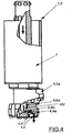
- the invention relates to a method for down-the-hole drilling, the drilling being carried out by an apparatus, having a drilling device 1 that comprises a casing part 2 and at least during a drilling situation an essentially inside thereof existing drilling unit 3, at the drilling head of which there are at least first drilling means 4 for drilling a center hole, second drilling means 5 for reaming the center hole for the casing part 2 and a pneumatic flushing flow arrangement 6 for leading of drilling waste by influence of pressurized air at least partly upward.
- the first drilling means 4 are coupled with the second drilling means 5 first of all power-transmittedly in order to carry out cooperation thereof at least during a drilling situation with the second drilling means 5 for a rotational motion w4, a feeding motion z4 and/or a hammering motion t4 produced by a hammer device 7 and on the other hand removably in order to enable removal thereof from the hole.
- the casing part 2 is furthermore arranged to be drawn into a hole to be drilled by the drilling unit 3. Flushing air is led while being led onto the drilling surface P1, P2 of the first and/or second drilling means into a counterpart surface arrangement X existing essentially at an end of a drilling unit 3, particularly in order to decrease kinetic energy thereof by changing its flow direction prior to drifting thereof into the ground.
- the drilling head of the drilling device 1 is formed of a first frame part 4a and a second frame part 5a, the drilling surfaces P1, P2 of which being provided with drilling organs of the first and the second drilling means 4, 5, such as an integrated drilling part, separate drilling pieces, bits or like, and whereby a reamer is being used as the second drilling means 5 that has an essentially continuing drilling surface radially when viewed in a cross-section perpendicular to a longitudinal direction s of the drilling unit 3.
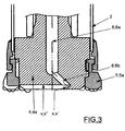
- the flushing air is in this case being led as an advantageous embodiment particularly with reference to the implementations shown in figure 3 from a main channel 6; 6a in the first frame part 4a by one or several distribution channels 6; 6b directed outward from center toward a counterpart surface X' existing in the first frame part.
- the method is exploited when operating with a drilling apparatus, in which the drilling head of the drilling device 1 is formed of a first frame part 4a and a second frame part 5a, the drilling surfaces P1, P2 of which being provided with drilling organs of the first and the second drilling means 4, 5, such as an integrated drilling parts, separate drilling pieces, bits or like, and whereby a reamer is being used as the second drilling means 5 that operates on eccentric principle, being non-cymmetrical and that opens radially outward for drilling.
- the flushing air is in this case being led from a main channel 6; 6a in the first frame part 4a by one or several distribution channels 6; 6b, being directed outward from center, toward a counterpart surface X' existing in the first 4a frame part.
- speed and/or direction of the flushing air flow HV is altered by a flow space X", being in connection with the counterpart surface X; X' and the cross-section of which being increased in respect to the same of the distribution channel 6; 6b and/or directed to a differing direction.
- the invention relates also to an apparatus for down-the-hole drilling as explained above, in which an end of the drilling unit 3 is provided with a counterpart surface arrangement X, which is meant particularly for decreasing kinetic energy of a flushing air flow HV to be brought into the drilling surface P1, P2 of the first and/or second drilling means, by changing its flow direction prior to drifting thereof into the ground.
- a drilling head of the drilling device 1 of the apparatus according to the invention is formed furthermore advantageously of a first frame part 4a and a second frame part 5a, the drilling surfaces P1, P2 of which being provided with drilling organs of the first and the second drilling means 4, 5, such as an integrated drilling part, separate drilling pieces, bits or like.
- the second drilling means 5 comprise a reamer that has an essentially continuing drilling surface radially when viewed in a cross-section perpendicular to a longitudinal direction s of the drilling unit 3.
- the flushing flow arrangement comprises a counterpart surface X; X' in the first frame part 4a.
- one or several distribution channels 6; 6b existing in the first frame part 4a and being directed outward from center, is/are led toward the above counterpart surface.
- a reamer is being used as the second drilling means 5 that operates on eccentric principle, being non-cymmetrical and that opens radially outward for drilling.
- the flushing flow arrangement comprises first of all a counterpart surface X; X' in the first frame part 4a.
- the counterpart surface arrangement comprises furthermore a flow space X", the cross-section of which is increased in respect to the distribution channel 6; 6b and/or being directed to a differing direction therefrom as shown in figure 3 particularly in order to alter speed and/or direction of the flushing air flow HV.
- the flow space X; X" is arranged by a recess in the first frame part 4a, at an end of the distribution channel 6; 6b on the drilling surface P1.
- the counterpart surface X; X' is arranged essentially perpendicularly to the flushing air flow HV.
- the casing shoe can be placed in an integrated manner at the end of the casing part etc. It is furthermore possible to complement the flushing flow arrangement e.g. by a flow pipe connected to the space between the casing part and the drilling unit e.g. in order to keep the space surrounding the drilling unit empty, and/or by a flushing assembly that greases the joint between the drilling means and the casing shoe etc.
Landscapes
- Engineering & Computer Science (AREA)
- Life Sciences & Earth Sciences (AREA)
- Geology (AREA)
- Mining & Mineral Resources (AREA)
- Physics & Mathematics (AREA)
- Environmental & Geological Engineering (AREA)
- Fluid Mechanics (AREA)
- General Life Sciences & Earth Sciences (AREA)
- Geochemistry & Mineralogy (AREA)
- Mechanical Engineering (AREA)
- Earth Drilling (AREA)
Claims (6)
- Verfahren für Bohren im Bohrloch, wobei das Bohren mit einer Vorrichtung durchgeführt wird, die eine Bohrvorrichtung (1) beinhaltet, die ein Mantelteil (2) und zumindest während einer Bohrsituation eine im Wesentlichen innerhalb desselben vorhandene Bohreinheit (3) umfasst, deren Bohrkopf mindestens erste Bohrmittel (4) zum Bohren eines zentralen Bohrlochs aufweist, zweite Bohrmittel (5) zum Erweitern des zentralen Bohrlochs für das Mantelteil (2) und eine Spülvorrichtung (6) zum Einleiten einer unter Druck stehenden Bohrspülluft durch einen zentrischen Hauptkanal (6a1), um die Spülluft mittels eines oder mehrerer Verteilerkanäle (6b) vom zentrischen Hauptkanal durch eine Bohrfläche (P1) der ersten Bohrmittel (4) zu leiten und Bohrklein zumindest teilweise nach oben zu leiten, wobei die ersten Bohrmittel (4) kraftübertragend mit den zweiten Bohrmitteln (5) gekoppelt sind, um ihr Zusammenwirken zumindest während einer Bohrsituation mit den zweiten Bohrmitteln (5) für eine Drehbewegung (w4), eine Vorschubbewegung (z4) und/oder eine Rammbewegung (t4) zu bewirken, wobei die direkte Ausrichtung eines Spülluftstroms (HV) auf das Erdreich mittels einer Gegenflächenanordnung verhindert wird, um die kinetische Energie des Spülluftstroms vor seiner Ableitung in den Boden zu verringern, indem die Spülluft an einem Ende der Bohreinheit (3) in eine Gegenfläche (X') und einen Strömungsraum (X") gelenkt wird, durch die Richtung und Geschwindigkeit des Spülluftstroms (HV) geändert werden, wobei ein Querschnitt des Strömungsraums in Bezug auf einen Querschnitt des Verteilungskanals (6b) vergrößert und der Strömungsraum in eine andere Richtung als der Verteilungskanal gerichtet ist und wobei der Bohrkopf der Bohrvorrichtung (1) aus einem ersten Rahmenteil (4a) und einem zweiten Rahmenteil (5a) gebildet wird, die jeweils die Bohrfläche (P1) der ersten Bohrmittel (4) und eine Bohrfläche (P2) der zweiten Bohrmittel (5) umfassen und jeweils mit Bohrorganen der ersten und der zweiten Bohrmittel (4, 5) versehen sind, wie beispielsweise einem integrierten Bohrteil, separaten Bohrstücken, Bohrkronen oder dergleichen, dadurch gekennzeichnet, dass die Spülluft durch den Verteilungskanal (6b) zu dem Strömungsraum (X; X") geleitet wird, der durch eine Aussparung und die Gegenfläche (X; X') im ersten Rahmenteil (4a) am Ende des Verteilungskanals auf der Bohrfläche (P1) der ersten Bohrmittel (4) gebildet wird.
- Verfahren nach Anspruch 1, dadurch gekennzeichnet, dass bei dem Verfahren in der Bohrvorrichtung ein Bohrlochräumer als zweites Bohrmittel (5) verwendet wird, der bei Betrachtung in einem Querschnitt senkrecht zu einer Längsrichtung (s) der Bohreinheit (3) eine im Wesentlichen radial fortgesetzte Bohrfläche aufweist und wobei die ersten Bohrmittel (4) demontierbar mit den zweiten Bohrmitteln (5) gekoppelt sind, um deren Entfernung aus dem gebohrten Loch zu ermöglichen.
- Verfahren nach Anspruch 1, dadurch gekennzeichnet, dass bei dem Verfahren in der Bohrvorrichtung ein Bohrlochräumer als zweites Bohrmittel (5) verwendet wird, der nach exzentrischem Funktionsprinzip arbeitet, unsymmetrisch ist und sich zum Bohren radial nach außen öffnet.
- Vorrichtung zum Bohren im Bohrloch mit einer Bohrvorrichtung (1), die ein Mantelteil (2) und zumindest während einer Bohrsituation eine im Wesentlichen innerhalb desselben vorhandene Bohreinheit (3) umfasst, deren Bohrkopf mindestens erste Bohrmittel (4) zum Bohren eines zentralen Bohrlochs aufweist, zweite Bohrmittel (5) zum Erweitern des zentralen Bohrlochs für das Mantelteil (2) und eine Spülvorrichtung (6) zum Einleiten einer unter Druck stehenden Bohrspülluft durch einen zentrischen Hauptkanal (6a1), um die Spülluft mittels eines oder mehrerer Verteilerkanäle (6b) vom zentrischen Hauptkanal durch eine Bohrfläche (P1) der ersten Bohrmittel (4) zu leiten und um Bohrklein durch Einwirkung der unter Druck stehenden Spülluft zumindest teilweise nach oben zu leiten, wobei die ersten Bohrmittel (4) kraftübertragend mit den zweiten Bohrmitteln (5) gekoppelt sind, um ihr Zusammenwirken zumindest während einer Bohrsituation mit dem zweiten Bohrmittel (5) für eine Drehbewegung (w4), eine Vorschubbewegung (z4) und/oder eine Rammbewegung (t4) zu bewirken, wobei die Bohreinheit (3) zur Verhinderung einer direkten Ausrichtung eines Spülluftstroms (HV) auf das Erdreich eine Gegenflächenanordnung aufweist, um die kinetische Energie des Spülluftstroms vor seiner Ableitung in den Boden mittels einer Gegenfläche (X') und eines Strömungsraums (X"), die Richtung und Geschwindigkeit des Spülluftstroms (HV) ändern, zu verringern, wobei ein Querschnitt des Strömungsraums in Bezug auf einen Querschnitt des Verteilungskanals (6b) vergrößert und der Strömungsraum in eine andere Richtung als der Verteilungskanal gerichtet ist und wobei der Bohrkopf der Bohrvorrichtung (1) aus einem ersten Rahmenteil (4a) und einem zweiten Rahmenteil (5a) gebildet wird, die jeweils die Bohrfläche (P1) der ersten Bohrmittel (4) und eine Bohrfläche (P2) der zweiten Bohrmittel (5) umfassen und jeweils mit Bohrorganen der ersten und der zweiten Bohrmittel (4, 5) versehen sind, wie beispielsweise integrierten Bohrteilen, separaten Bohrstücken, Bohrkronen oder dergleichen, dadurch gekennzeichnet, dass der Strömungsraum (X") durch eine Aussparung und die Gegenfläche (X;X') im ersten Rahmenteil (4a) am Ende des Verteilungskanals auf der Bohrfläche (P1) der ersten Bohrmittel (4) gebildet wird.
- Vorrichtung nach Anspruch 4, dadurch gekennzeichnet, dass die zweiten Bohrmittel (5) einen Bohrlochräumer umfassen, der bei Betrachtung in einem Querschnitt senkrecht zu einer Längsrichtung (s) der Bohreinheit (3) eine im Wesentlichen radial fortgesetzte Bohrfläche aufweist und wobei die ersten Bohrmittel (4) demontierbar mit den zweiten Bohrmitteln (5) gekoppelt sind, um deren Entfernung aus dem Bohrloch zu ermöglichen.
- Vorrichtung nach Anspruch 4, dadurch gekennzeichnet, dass die zweiten Bohrmittel (5) einen Bohrlochräumer umfassen, der nach exzentrischem Funktionsprinzip arbeitet, unsymmetrisch ist und sich zum Bohren radial nach außen öffnet.
Applications Claiming Priority (2)
| Application Number | Priority Date | Filing Date | Title |
|---|---|---|---|
| FI20086206A FI20086206A0 (fi) | 2008-12-17 | 2008-12-17 | Menetelmä ja laitteisto uppoporaukseen |
| PCT/FI2009/050820 WO2010070190A1 (en) | 2008-12-17 | 2009-10-13 | Method and apparatus for down-the-hole drilling |
Publications (3)
| Publication Number | Publication Date |
|---|---|
| EP2370660A1 EP2370660A1 (de) | 2011-10-05 |
| EP2370660A4 EP2370660A4 (de) | 2018-02-21 |
| EP2370660B1 true EP2370660B1 (de) | 2020-07-15 |
Family
ID=40240604
Family Applications (1)
| Application Number | Title | Priority Date | Filing Date |
|---|---|---|---|
| EP09832986.5A Active EP2370660B1 (de) | 2008-12-17 | 2009-10-13 | Verfahren und vorrichtung für bohren im bohrloch |
Country Status (3)
| Country | Link |
|---|---|
| EP (1) | EP2370660B1 (de) |
| FI (1) | FI20086206A0 (de) |
| WO (1) | WO2010070190A1 (de) |
Families Citing this family (5)
| Publication number | Priority date | Publication date | Assignee | Title |
|---|---|---|---|---|
| FI20106154A0 (fi) * | 2010-11-03 | 2010-11-03 | Atlas Copco Rotex Ab Oy | Menetelmä ja laitteisto maaputken kytkemiseksi maaperään |
| CN102477846B (zh) * | 2010-11-27 | 2014-04-30 | 中铁西北科学研究院有限公司 | 土层扩孔钻头 |
| WO2017089647A1 (en) * | 2015-11-26 | 2017-06-01 | Oy Atlas Copco Rotex Ab | Method in down-the-hole drilling and a down-the-hole drilling device |
| FI128986B (en) * | 2017-03-01 | 2021-04-30 | Robit Oyj | DRILL BLADE FOR IMPACT DRILLING, DRILL BLADE ASSEMBLY AND METHOD FOR MAKING SUCH A DRILL BLADE |
| CN110263497B (zh) * | 2019-07-19 | 2021-12-07 | 南京航空航天大学 | 一种基于相对增益的气动耦合影响分析方法 |
Family Cites Families (9)
| Publication number | Priority date | Publication date | Assignee | Title |
|---|---|---|---|---|
| SE421551B (sv) | 1980-03-26 | 1982-01-04 | Sandvik Ab | Borrverktyg for rotations- och/eller slagborrning |
| DE3039633C2 (de) * | 1980-10-21 | 1983-08-18 | Christensen, Inc., 84115 Salt Lake City, Utah | Drehbohrmeißel, insbesondere für Tiefbohrungen |
| FR2566832B1 (fr) * | 1984-06-27 | 1986-11-14 | Inst Francais Du Petrole | Methode et perfectionnement aux outils de forage permettant une grande efficacite du nettoyage du front de taille |
| FI95618C (fi) | 1992-12-03 | 1998-09-03 | Jorma Jaervelae | Porauslaitteisto |
| FI945367A7 (fi) * | 1994-11-14 | 1996-05-15 | Ilomaeki Valto | Porauslaitteen teräasetelma ja menetelmä porausjätteen poiskuljettamiseksi |
| FI98650C (fi) * | 1995-11-06 | 1997-07-25 | Valto Ilomaeki | Iskulaitteella varustettu porausyksikkö |
| EP1337734B1 (de) * | 2000-11-27 | 2011-04-06 | Shell Internationale Research Maatschappij B.V. | Bohrer |
| EP1731708B1 (de) * | 2005-06-10 | 2007-08-08 | Geomechanik Wasser- und Umwelttechnik GmbH | Senkhammer-Bohrvorrichtung und -verfahren |
| FR2889556B1 (fr) * | 2005-08-04 | 2007-09-21 | Gerard Arsonnet | Dispositif de forage d'un puits suivant un axe de forage pour mesurer un parametre d'une partie d'un sol |
-
2008
- 2008-12-17 FI FI20086206A patent/FI20086206A0/fi not_active Application Discontinuation
-
2009
- 2009-10-13 WO PCT/FI2009/050820 patent/WO2010070190A1/en not_active Ceased
- 2009-10-13 EP EP09832986.5A patent/EP2370660B1/de active Active
Non-Patent Citations (1)
| Title |
|---|
| None * |
Also Published As
| Publication number | Publication date |
|---|---|
| WO2010070190A1 (en) | 2010-06-24 |
| EP2370660A4 (de) | 2018-02-21 |
| FI20086206A0 (fi) | 2008-12-17 |
| EP2370660A1 (de) | 2011-10-05 |
Similar Documents
| Publication | Publication Date | Title |
|---|---|---|
| EP2382368B1 (de) | Verfahren und vorrichtung für abwärtslochbohrungen | |
| US4671367A (en) | Pole hole digger with percussive core drilling | |
| KR101406159B1 (ko) | 말뚝공 굴착 장치 | |
| WO2010070190A1 (en) | Method and apparatus for down-the-hole drilling | |
| KR101302554B1 (ko) | 지반 천공용 해머의 비트 | |
| US20110198129A1 (en) | Method and drilling apparatus for down-the-hole drilling | |
| US20100175928A1 (en) | Hammer bit | |
| EP2675982B1 (de) | Verfahren und vorrichtung für abwärtslochbohrungen | |
| CN112982400A (zh) | 护筒跟进型旋挖钻孔灌注桩钻具 | |
| CN205063813U (zh) | 一种集束锤 | |
| EP0990765B1 (de) | Schlagkernbehälter | |
| HK1189925A (en) | Method and apparatus for down-the-hole drilling | |
| HK1189925B (en) | Method and apparatus for down-the-hole drilling | |
| KR102505718B1 (ko) | 연약지반 굴착용 비트 | |
| US12291924B2 (en) | Excavation boring and shoring tool | |
| KR100858865B1 (ko) | 천공비트. | |
| KR102818076B1 (ko) | 장심도 일체형 prd 굴착공법 | |
| KR100328367B1 (ko) | 건축공사용 굴착기의 헤드 | |
| KR100323302B1 (ko) | 크레인을 이용한 천공기의 배토장치 | |
| KR101396911B1 (ko) | 연속굴반기의 에어챔버 분리형 드릴비트 조립체 및 이를 구비한 연속굴반기 | |
| EP3433463B1 (de) | Abwärtsbohrvorrichtung | |
| RU23905U1 (ru) | Ударный бур | |
| KR20130033566A (ko) | 강관파일과 메인비트의 탈부착이 용이한 지하 천공기용 비트 | |
| HK1026933B (en) | Percussive core barrel |
Legal Events
| Date | Code | Title | Description |
|---|---|---|---|
| PUAI | Public reference made under article 153(3) epc to a published international application that has entered the european phase |
Free format text: ORIGINAL CODE: 0009012 |
|
| 17P | Request for examination filed |
Effective date: 20110628 |
|
| AK | Designated contracting states |
Kind code of ref document: A1 Designated state(s): AT BE BG CH CY CZ DE DK EE ES FI FR GB GR HR HU IE IS IT LI LT LU LV MC MK MT NL NO PL PT RO SE SI SK SM TR |
|
| DAX | Request for extension of the european patent (deleted) | ||
| RAP1 | Party data changed (applicant data changed or rights of an application transferred) |
Owner name: OY EPIROC DRILLING TOOLS AB |
|
| RA4 | Supplementary search report drawn up and despatched (corrected) |
Effective date: 20180123 |
|
| RIC1 | Information provided on ipc code assigned before grant |
Ipc: E21B 10/60 20060101ALI20180117BHEP Ipc: E21B 10/38 20060101AFI20180117BHEP Ipc: E21B 10/26 20060101ALI20180117BHEP Ipc: E21B 21/16 20060101ALI20180117BHEP Ipc: E21B 7/20 20060101ALI20180117BHEP |
|
| STAA | Information on the status of an ep patent application or granted ep patent |
Free format text: STATUS: EXAMINATION IS IN PROGRESS |
|
| 17Q | First examination report despatched |
Effective date: 20181019 |
|
| RAP1 | Party data changed (applicant data changed or rights of an application transferred) |
Owner name: TERRAROC FINLAND OY |
|
| GRAP | Despatch of communication of intention to grant a patent |
Free format text: ORIGINAL CODE: EPIDOSNIGR1 |
|
| STAA | Information on the status of an ep patent application or granted ep patent |
Free format text: STATUS: GRANT OF PATENT IS INTENDED |
|
| INTG | Intention to grant announced |
Effective date: 20200224 |
|
| GRAS | Grant fee paid |
Free format text: ORIGINAL CODE: EPIDOSNIGR3 |
|
| GRAA | (expected) grant |
Free format text: ORIGINAL CODE: 0009210 |
|
| STAA | Information on the status of an ep patent application or granted ep patent |
Free format text: STATUS: THE PATENT HAS BEEN GRANTED |
|
| AK | Designated contracting states |
Kind code of ref document: B1 Designated state(s): AT BE BG CH CY CZ DE DK EE ES FI FR GB GR HR HU IE IS IT LI LT LU LV MC MK MT NL NO PL PT RO SE SI SK SM TR |
|
| REG | Reference to a national code |
Ref country code: CH Ref legal event code: EP Ref country code: GB Ref legal event code: FG4D |
|
| REG | Reference to a national code |
Ref country code: IE Ref legal event code: FG4D |
|
| REG | Reference to a national code |
Ref country code: DE Ref legal event code: R096 Ref document number: 602009062437 Country of ref document: DE |
|
| REG | Reference to a national code |
Ref country code: AT Ref legal event code: REF Ref document number: 1291236 Country of ref document: AT Kind code of ref document: T Effective date: 20200815 |
|
| REG | Reference to a national code |
Ref country code: FI Ref legal event code: FGE |
|
| REG | Reference to a national code |
Ref country code: SE Ref legal event code: TRGR |
|
| REG | Reference to a national code |
Ref country code: LT Ref legal event code: MG4D |
|
| REG | Reference to a national code |
Ref country code: AT Ref legal event code: MK05 Ref document number: 1291236 Country of ref document: AT Kind code of ref document: T Effective date: 20200715 |
|
| REG | Reference to a national code |
Ref country code: NL Ref legal event code: MP Effective date: 20200715 |
|
| PG25 | Lapsed in a contracting state [announced via postgrant information from national office to epo] |
Ref country code: HR Free format text: LAPSE BECAUSE OF FAILURE TO SUBMIT A TRANSLATION OF THE DESCRIPTION OR TO PAY THE FEE WITHIN THE PRESCRIBED TIME-LIMIT Effective date: 20200715 Ref country code: ES Free format text: LAPSE BECAUSE OF FAILURE TO SUBMIT A TRANSLATION OF THE DESCRIPTION OR TO PAY THE FEE WITHIN THE PRESCRIBED TIME-LIMIT Effective date: 20200715 Ref country code: NO Free format text: LAPSE BECAUSE OF FAILURE TO SUBMIT A TRANSLATION OF THE DESCRIPTION OR TO PAY THE FEE WITHIN THE PRESCRIBED TIME-LIMIT Effective date: 20201015 Ref country code: GR Free format text: LAPSE BECAUSE OF FAILURE TO SUBMIT A TRANSLATION OF THE DESCRIPTION OR TO PAY THE FEE WITHIN THE PRESCRIBED TIME-LIMIT Effective date: 20201016 Ref country code: AT Free format text: LAPSE BECAUSE OF FAILURE TO SUBMIT A TRANSLATION OF THE DESCRIPTION OR TO PAY THE FEE WITHIN THE PRESCRIBED TIME-LIMIT Effective date: 20200715 Ref country code: LT Free format text: LAPSE BECAUSE OF FAILURE TO SUBMIT A TRANSLATION OF THE DESCRIPTION OR TO PAY THE FEE WITHIN THE PRESCRIBED TIME-LIMIT Effective date: 20200715 Ref country code: PT Free format text: LAPSE BECAUSE OF FAILURE TO SUBMIT A TRANSLATION OF THE DESCRIPTION OR TO PAY THE FEE WITHIN THE PRESCRIBED TIME-LIMIT Effective date: 20201116 Ref country code: BG Free format text: LAPSE BECAUSE OF FAILURE TO SUBMIT A TRANSLATION OF THE DESCRIPTION OR TO PAY THE FEE WITHIN THE PRESCRIBED TIME-LIMIT Effective date: 20201015 |
|
| PG25 | Lapsed in a contracting state [announced via postgrant information from national office to epo] |
Ref country code: PL Free format text: LAPSE BECAUSE OF FAILURE TO SUBMIT A TRANSLATION OF THE DESCRIPTION OR TO PAY THE FEE WITHIN THE PRESCRIBED TIME-LIMIT Effective date: 20200715 Ref country code: LV Free format text: LAPSE BECAUSE OF FAILURE TO SUBMIT A TRANSLATION OF THE DESCRIPTION OR TO PAY THE FEE WITHIN THE PRESCRIBED TIME-LIMIT Effective date: 20200715 Ref country code: IS Free format text: LAPSE BECAUSE OF FAILURE TO SUBMIT A TRANSLATION OF THE DESCRIPTION OR TO PAY THE FEE WITHIN THE PRESCRIBED TIME-LIMIT Effective date: 20201115 |
|
| PG25 | Lapsed in a contracting state [announced via postgrant information from national office to epo] |
Ref country code: NL Free format text: LAPSE BECAUSE OF FAILURE TO SUBMIT A TRANSLATION OF THE DESCRIPTION OR TO PAY THE FEE WITHIN THE PRESCRIBED TIME-LIMIT Effective date: 20200715 |
|
| REG | Reference to a national code |
Ref country code: DE Ref legal event code: R097 Ref document number: 602009062437 Country of ref document: DE |
|
| PG25 | Lapsed in a contracting state [announced via postgrant information from national office to epo] |
Ref country code: RO Free format text: LAPSE BECAUSE OF FAILURE TO SUBMIT A TRANSLATION OF THE DESCRIPTION OR TO PAY THE FEE WITHIN THE PRESCRIBED TIME-LIMIT Effective date: 20200715 Ref country code: SM Free format text: LAPSE BECAUSE OF FAILURE TO SUBMIT A TRANSLATION OF THE DESCRIPTION OR TO PAY THE FEE WITHIN THE PRESCRIBED TIME-LIMIT Effective date: 20200715 Ref country code: IT Free format text: LAPSE BECAUSE OF FAILURE TO SUBMIT A TRANSLATION OF THE DESCRIPTION OR TO PAY THE FEE WITHIN THE PRESCRIBED TIME-LIMIT Effective date: 20200715 Ref country code: DK Free format text: LAPSE BECAUSE OF FAILURE TO SUBMIT A TRANSLATION OF THE DESCRIPTION OR TO PAY THE FEE WITHIN THE PRESCRIBED TIME-LIMIT Effective date: 20200715 Ref country code: EE Free format text: LAPSE BECAUSE OF FAILURE TO SUBMIT A TRANSLATION OF THE DESCRIPTION OR TO PAY THE FEE WITHIN THE PRESCRIBED TIME-LIMIT Effective date: 20200715 Ref country code: CZ Free format text: LAPSE BECAUSE OF FAILURE TO SUBMIT A TRANSLATION OF THE DESCRIPTION OR TO PAY THE FEE WITHIN THE PRESCRIBED TIME-LIMIT Effective date: 20200715 |
|
| REG | Reference to a national code |
Ref country code: DE Ref legal event code: R119 Ref document number: 602009062437 Country of ref document: DE |
|
| PLBE | No opposition filed within time limit |
Free format text: ORIGINAL CODE: 0009261 |
|
| STAA | Information on the status of an ep patent application or granted ep patent |
Free format text: STATUS: NO OPPOSITION FILED WITHIN TIME LIMIT |
|
| REG | Reference to a national code |
Ref country code: CH Ref legal event code: PL |
|
| 26N | No opposition filed |
Effective date: 20210416 |
|
| GBPC | Gb: european patent ceased through non-payment of renewal fee |
Effective date: 20201015 |
|
| PG25 | Lapsed in a contracting state [announced via postgrant information from national office to epo] |
Ref country code: LU Free format text: LAPSE BECAUSE OF NON-PAYMENT OF DUE FEES Effective date: 20201013 Ref country code: SK Free format text: LAPSE BECAUSE OF FAILURE TO SUBMIT A TRANSLATION OF THE DESCRIPTION OR TO PAY THE FEE WITHIN THE PRESCRIBED TIME-LIMIT Effective date: 20200715 Ref country code: MC Free format text: LAPSE BECAUSE OF FAILURE TO SUBMIT A TRANSLATION OF THE DESCRIPTION OR TO PAY THE FEE WITHIN THE PRESCRIBED TIME-LIMIT Effective date: 20200715 |
|
| REG | Reference to a national code |
Ref country code: BE Ref legal event code: MM Effective date: 20201031 |
|
| PG25 | Lapsed in a contracting state [announced via postgrant information from national office to epo] |
Ref country code: DE Free format text: LAPSE BECAUSE OF NON-PAYMENT OF DUE FEES Effective date: 20210501 Ref country code: FR Free format text: LAPSE BECAUSE OF NON-PAYMENT OF DUE FEES Effective date: 20201031 |
|
| PG25 | Lapsed in a contracting state [announced via postgrant information from national office to epo] |
Ref country code: SI Free format text: LAPSE BECAUSE OF FAILURE TO SUBMIT A TRANSLATION OF THE DESCRIPTION OR TO PAY THE FEE WITHIN THE PRESCRIBED TIME-LIMIT Effective date: 20200715 Ref country code: LI Free format text: LAPSE BECAUSE OF NON-PAYMENT OF DUE FEES Effective date: 20201031 Ref country code: GB Free format text: LAPSE BECAUSE OF NON-PAYMENT OF DUE FEES Effective date: 20201015 Ref country code: BE Free format text: LAPSE BECAUSE OF NON-PAYMENT OF DUE FEES Effective date: 20201031 Ref country code: CH Free format text: LAPSE BECAUSE OF NON-PAYMENT OF DUE FEES Effective date: 20201031 |
|
| PG25 | Lapsed in a contracting state [announced via postgrant information from national office to epo] |
Ref country code: TR Free format text: LAPSE BECAUSE OF FAILURE TO SUBMIT A TRANSLATION OF THE DESCRIPTION OR TO PAY THE FEE WITHIN THE PRESCRIBED TIME-LIMIT Effective date: 20200715 Ref country code: MT Free format text: LAPSE BECAUSE OF FAILURE TO SUBMIT A TRANSLATION OF THE DESCRIPTION OR TO PAY THE FEE WITHIN THE PRESCRIBED TIME-LIMIT Effective date: 20200715 Ref country code: CY Free format text: LAPSE BECAUSE OF FAILURE TO SUBMIT A TRANSLATION OF THE DESCRIPTION OR TO PAY THE FEE WITHIN THE PRESCRIBED TIME-LIMIT Effective date: 20200715 |
|
| PG25 | Lapsed in a contracting state [announced via postgrant information from national office to epo] |
Ref country code: MK Free format text: LAPSE BECAUSE OF FAILURE TO SUBMIT A TRANSLATION OF THE DESCRIPTION OR TO PAY THE FEE WITHIN THE PRESCRIBED TIME-LIMIT Effective date: 20200715 |
|
| P01 | Opt-out of the competence of the unified patent court (upc) registered |
Effective date: 20230528 |
|
| PGFP | Annual fee paid to national office [announced via postgrant information from national office to epo] |
Ref country code: SE Payment date: 20231031 Year of fee payment: 15 Ref country code: IE Payment date: 20231031 Year of fee payment: 15 Ref country code: FI Payment date: 20231031 Year of fee payment: 15 |
|
| REG | Reference to a national code |
Ref country code: SE Ref legal event code: EUG |
|
| PG25 | Lapsed in a contracting state [announced via postgrant information from national office to epo] |
Ref country code: FI Free format text: LAPSE BECAUSE OF NON-PAYMENT OF DUE FEES Effective date: 20241013 |
|
| PG25 | Lapsed in a contracting state [announced via postgrant information from national office to epo] |
Ref country code: SE Free format text: LAPSE BECAUSE OF NON-PAYMENT OF DUE FEES Effective date: 20241014 |
|
| PG25 | Lapsed in a contracting state [announced via postgrant information from national office to epo] |
Ref country code: IE Free format text: LAPSE BECAUSE OF NON-PAYMENT OF DUE FEES Effective date: 20241013 |