EP2370795B1 - Système de mesure pour déterminer et/ou surveiller par ultrasons le débit d'un milieu de mesure dans le tube de mesure - Google Patents
Système de mesure pour déterminer et/ou surveiller par ultrasons le débit d'un milieu de mesure dans le tube de mesure Download PDFInfo
- Publication number
- EP2370795B1 EP2370795B1 EP09774894.1A EP09774894A EP2370795B1 EP 2370795 B1 EP2370795 B1 EP 2370795B1 EP 09774894 A EP09774894 A EP 09774894A EP 2370795 B1 EP2370795 B1 EP 2370795B1
- Authority
- EP
- European Patent Office
- Prior art keywords
- measuring tube
- ultrasonic transducer
- measuring
- ultrasonic
- transducer
- Prior art date
- Legal status (The legal status is an assumption and is not a legal conclusion. Google has not performed a legal analysis and makes no representation as to the accuracy of the status listed.)
- Not-in-force
Links
- 238000002604 ultrasonography Methods 0.000 title description 21
- 238000012544 monitoring process Methods 0.000 title description 4
- 230000008878 coupling Effects 0.000 claims description 49
- 238000010168 coupling process Methods 0.000 claims description 49
- 238000005859 coupling reaction Methods 0.000 claims description 49
- 238000011161 development Methods 0.000 description 10
- 230000033001 locomotion Effects 0.000 description 9
- 238000005259 measurement Methods 0.000 description 9
- 239000007788 liquid Substances 0.000 description 8
- 230000007246 mechanism Effects 0.000 description 7
- 238000000034 method Methods 0.000 description 4
- 230000008569 process Effects 0.000 description 4
- 230000008859 change Effects 0.000 description 3
- 230000006978 adaptation Effects 0.000 description 2
- 230000005540 biological transmission Effects 0.000 description 2
- 230000001143 conditioned effect Effects 0.000 description 2
- 230000001419 dependent effect Effects 0.000 description 2
- 238000006073 displacement reaction Methods 0.000 description 2
- 238000004519 manufacturing process Methods 0.000 description 2
- 229920003023 plastic Polymers 0.000 description 2
- 239000004033 plastic Substances 0.000 description 2
- 125000006850 spacer group Chemical group 0.000 description 2
- 230000009471 action Effects 0.000 description 1
- 230000008901 benefit Effects 0.000 description 1
- 238000004364 calculation method Methods 0.000 description 1
- 239000000356 contaminant Substances 0.000 description 1
- 238000013461 design Methods 0.000 description 1
- 238000005516 engineering process Methods 0.000 description 1
- 238000011156 evaluation Methods 0.000 description 1
- 210000003746 feather Anatomy 0.000 description 1
- 238000009434 installation Methods 0.000 description 1
- 238000010409 ironing Methods 0.000 description 1
- 239000000463 material Substances 0.000 description 1
- 238000003032 molecular docking Methods 0.000 description 1
- 239000002243 precursor Substances 0.000 description 1
- 230000005855 radiation Effects 0.000 description 1
- 230000009467 reduction Effects 0.000 description 1
- 230000035945 sensitivity Effects 0.000 description 1
- 239000007787 solid Substances 0.000 description 1
- 230000007704 transition Effects 0.000 description 1
- 238000011144 upstream manufacturing Methods 0.000 description 1
Images



Classifications
-
- G—PHYSICS
- G01—MEASURING; TESTING
- G01F—MEASURING VOLUME, VOLUME FLOW, MASS FLOW OR LIQUID LEVEL; METERING BY VOLUME
- G01F1/00—Measuring the volume flow or mass flow of fluid or fluent solid material wherein the fluid passes through a meter in a continuous flow
- G01F1/66—Measuring the volume flow or mass flow of fluid or fluent solid material wherein the fluid passes through a meter in a continuous flow by measuring frequency, phase shift or propagation time of electromagnetic or other waves, e.g. using ultrasonic flowmeters
- G01F1/662—Constructional details
Definitions
- the present invention relates to a measuring system for determining and / or monitoring the flow of a measuring medium through the measuring tube by means of ultrasound, with a first ultrasonic transducer and at least one further second ultrasonic transducer, wherein the measuring tube has a measuring tube inlet and a measuring tube outlet and a first ultrasonic transducer holder and at least one further second ultrasonic transducer receiving, wherein the first ultrasonic transducer is releasably coupled acoustically with the first ultrasonic transducer recording of the measuring tube and wherein the second ultrasonic transducer is releasably coupled to the second ultrasonic transducer recording of the measuring tube acoustically.
- Ultrasonic flowmeters are widely used in process and automation technology. They allow in a simple way to determine the volume flow and / or mass flow in a pipeline.
- the known ultrasonic flowmeters often work according to the Doppler or the transit time difference principle.
- ultrasonic pulses are sent at a certain angle to the pipe axis both with and against the flow.
- the runtime difference can be used to determine the flow velocity and, with a known diameter of the pipe section, the volume flow rate.
- ultrasonic waves of a certain frequency are coupled into the liquid and the ultrasonic waves reflected by the liquid are evaluated. From the frequency shift between the coupled and reflected waves can also determine the flow rate of the liquid.
- the ultrasonic waves are generated or received with the help of so-called ultrasonic transducers.
- ultrasonic transducers on the pipe wall of the respective pipe section firmly attached.
- clamp-on ultrasonic flow measurement systems have become available. In these systems, the ultrasonic transducers are pressed against the pipe wall only with a tension lock.
- Such systems are for. B. from the EP 686 255 B1 . US-A 44 84 478 or US-A 45 98 593 known.
- Another ultrasonic flowmeter which operates on the transit time difference principle, is from the US-A 50 52 230 known.
- the transit time is determined here by means of short ultrasound pulses.
- a big advantage of clamp-on ultrasonic flow measuring systems is that they do not touch the measuring medium and are mounted on an existing pipeline.
- the ultrasound transducers normally consist of a piezoelectric element, also called piezo for short, and a coupling layer, also known as a coupling wedge or, more rarely, a precursor body.
- the coupling layer is usually made of plastic
- the piezoelectric element is in industrial process measurement usually a piezoceramic.
- the ultrasonic waves are generated and passed over the coupling layer to the pipe wall and passed from there into the liquid. Since the speeds of sound in liquids and plastics are different, the ultrasonic waves are refracted during the transition from one medium to another.
- the angle of refraction is determined in first approximation according to Snell's law. The angle of refraction is thus dependent on the ratio of the propagation velocities in the media.
- a further coupling layer may be arranged, a so-called adaptation layer.
- the adaptation layer assumes the function of the transmission of the ultrasonic signal and at the same time the reduction of a reflection caused by different acoustic impedances at boundary layers between two materials.
- the coupling elements corresponding input and / or decoupling surfaces, each having a Have angles to the piezoelectric elements, which in turn are arranged plane-parallel to each other and perpendicular to the Meßrohrachse.
- the sound-emitting or sound-receiving surfaces of the piezoelectric elements are at least the size of the diameter of the measuring tube.
- a disadvantage of angles between the sound-emitting or sound-receiving surfaces of the piezoelectric elements and the input and output surfaces of the coupling elements is that the sound velocities in the coupling elements and the measuring tube and / or in the measuring medium must be coordinated with each other and with the angles to one for Receive tube axis parallel signal path of the ultrasonic signal.
- the EP 1 760 436 A2 shows an ultrasonic flow measuring system with a measuring tube, which is axially ultrasonically transposed, with piezoelectric elements having a diameter of the sound-emitting or sound-receiving surfaces, which is at least equal to the diameter of the measuring tube.
- the input and / or decoupling surfaces of the coupling elements of the ultrasonic transducers for coupling or decoupling the ultrasonic signals into the measuring medium are convex.
- the measuring tube Immediately before the input and / or decoupling surfaces, ie in the region of the coupling or decoupling of the ultrasonic signals into or out of the measuring medium, the measuring tube has an enlarged cross section.
- the diameters of the substantially disk-shaped ultrasonic transducers are larger than the diameter of a substantial measuring section of the measuring tube. Due to the change in cross section of the measuring tube before the input and / or decoupling arise just before the input and / or decoupling chambers, where the measuring medium can collect.
- the flow of the measuring medium is slowed down before the input and / or decoupling surfaces and accelerated in the measuring tube, in a substantial part of the measuring section.
- the WO 2008/101662 A2 has a similar design of the measuring cell.
- the diameters of the measuring tube or measuring tube outlets and of the measuring tube itself are essentially the same here, the measuring tube inlet or measuring tube outlets are at an angle of less than 90 ° on the measuring tube axis, but here too the flow of the measuring medium before the inlet and / or or decoupling surfaces, which are again formed here by the coupling elements of the ultrasonic transducers inserted into the measuring cell and are arranged at an angle of 90 ° to the measuring tube axis, slows down.
- chambers are formed in front of the input and output surfaces.
- the sound-emitting or sound-receiving surfaces of the piezoelectric elements are larger than the diameter of the measuring tube, but the sound input or sound output surface of the coupling element axially closes the measuring tube and is therefore of the same size.
- the ultrasonic transducer can be detachably mounted to the measuring tube by means of a bayonet, screw, clip or snap lock.
- a measuring tube which in the region of an ultrasonic transducer receiving pin part of a bayonet closure, and an ultrasonic transducer is designed as a matching counterpart or as a matching second part of the bayonet closure and the measuring tube thus by means of rotation is detachably attachable.
- the invention has for its object to provide a high-precision measuring system with inexpensive exchangeable measuring tubes / measuring cells.
- a measuring system for determining and / or monitoring the flow of a measuring medium through a measuring tube with a first ultrasonic transducer and at least one further second ultrasonic transducer, wherein the measuring system comprises the measuring tube and a first ultrasonic transducer and at least one further second ultrasonic transducer, wherein the Measuring tube has a measuring tube inlet and a measuring tube outlet and a first ultrasonic transducer recording and at least one further, second ultrasonic transducer recording, wherein the first ultrasonic transducer is releasably coupled to the first ultrasonic transducer recording of the measuring tube acoustically and wherein the second ultrasonic transducer is detachably acoustically coupled to the second ultrasonic transducer recording of the measuring tube, wherein at least one ultrasonic transducer has at least one bracket, which bracket can be folded over and is designed such that the bracket in at least one arranged on the measuring tube survey or Recess is lat
- At least one ultrasonic transducer has at least one stirrup, which stirrup can be folded over and is designed such that the stirrup can be latched in at least one elevation or depression arranged on the measuring tube in a folded-over, and thus closed, state while simultaneously assuming the mounting position of the ultrasound transducer on the measuring tube
- the ultrasonic transducer engages in a recess or survey, hooks or even embraces it
- the ultrasonic transducer is detachably mounted on the measuring tube with the latching of the bracket and is acoustically coupled to the ultrasonic transducer recording of the measuring tube.
- the determination and / or monitoring of the flow takes place, for example, according to the principle of the transit time difference.
- Bumps or depressions are in particular cones, shoulders, annular grooves, Wellenschultem etc. They are e.g. Part of a shaft / hub connection or a spring / groove connection.
- the ultrasonic transducer and the depressions or elevations on the measuring tube are part of a fastening mechanism, in particular a closure.
- a fastening mechanism in particular a closure.
- the ultrasonic transducer is brought into the mounting position and automatically brought by folding the bracket in the measuring position. It is in particular a linear movement, which is forced to the ultrasonic transducer.
- an annular groove e.g. provided as a notch at the top of the measuring tube. In this the clip lock engages. If this notch also extends only partially around the transducer receptacle, an annular groove results from the notch, which can be regarded as a journal.
- One embodiment provides a closure, as is customary especially in travel suitcases, a so-called suitcase closure.
- the measuring tube has at least two pins on opposite sides of the measuring tube in the region of at least one ultrasonic transducer receptacle on the measuring tube outside.
- a pin designates in particular a projecting piece for the transmission of forces, in particular a remote end of an axle that can accommodate a bearing. spigot serve to connect components together.
- the pins lie in one axis.
- this axis lies in the spatial plane, which is spanned by the measuring tube axis and the measuring tube outlet axis and / or the measuring tube inlet axis.
- the part of the fastening mechanism which is arranged on the ultrasonic transducer consists of a bracket, e.g. a clamping yoke, and a clamping bracket, e.g. a tensioning lever, both of which are connected to each other via a first closure axis, wherein at least the bracket is rotatably mounted on the first closure axis, and a second closure axis, which connects the clamping bracket with the ultrasonic transducer housing, wherein at least the clamping bracket is rotatably mounted on the second closure axis.
- the bracket By turning the clamping bracket around the second locking axis, the bracket is folded over. He experiences a translational motion perpendicular to the second closure axis.
- At least one ultrasonic transducer has at least one first guide element for guiding the ultrasonic transducer on a base plate and the base plate has at least one, corresponding to the first guide element of the ultrasonic transducer matching second guide element for guiding the ultrasonic transducer on the base plate, wherein the first guide element and the second guide element are each part of a linear guide.
- the guide means are thus suitable for substantially fixing the ultrasonic transducer on the base plate in two cardinal directions, i. store immovably and to store in one direction at least over a certain area displaceable.
- the ultrasonic transducers are in particular secured against rotation relative to the base plate on the base plate.
- the measuring tube on the base plate attachable and the sensors also, which are still arranged in the direction of the measuring tube and away from it displaceable on the base plate.
- the base plate is not necessary to align and / or fix the ultrasonic transducers on the measuring tube, it is optional, ie it serves only as a support or as a mounting base for the whole measuring system, then mounting holes are provided on its underside to themselves to attach in the process. If it makes sense in the application, it is possible to disassemble the base plate and thus make the whole system more flexible and flexible.
- the measuring tube has at least one plug or at least one coupling for producing a plug connection between measuring tube and base plate on the measuring tube outside and the base plate corresponding to at least one plug or at least one coupling for producing the plug connection between measuring tube and Base plate has.
- This is optional, but it is also possible that no direct or no force and / or positive and / or cohesive connection between the base plate and the measuring tube is provided.
- the elevations or depressions in the region of the ultrasonic transducer recordings are arranged on the measuring tube.
- One embodiment provides pins in the range of ultrasonic transducer recordings.
- the ultrasound transducers each have at least one electromechanical transducer element or at least one electromechanical transducer element and at least one coupling element, which coupling elements are arranged between the electromechanical transducer elements of the ultrasound transducer and the ultrasound transducer receptacles of the measuring tube in the mounted state of the ultrasound transducer, which electromechanical transducer elements or which coupling elements can be coupled by means of a definable force with the ultrasonic transducer recordings of the measuring tube.
- the part of the ultrasonic transducer which is acoustically coupled during assembly with the measuring tube, so the electromechanical transducer element itself or a coupling element, which then stands between the electromechanical transducer element and the measuring tube, is prepared with a predetermined bias to the measuring tube or on the measuring tube to it Pressed ultrasound transducer recordings.
- the force can be applied by means of a spring between an ultrasonic transducer housing and a sensor cup, wherein the electromechanical transducer element is arranged on the sensor cup.
- the sensor cup is a component which is mounted displaceably relative to the ultrasound transducer housing only in one direction, in particular in the ultrasound transducer housing itself.
- the electromechanical transducer element is then attached or attached to a first side of the sensor cup.
- On the other side of the sensor cup is the spring.
- the spring thus provides the contact pressure for acoustic coupling of the ultrasonic transducer on the measuring tube.
- the ultrasonic transducer is by means of springs in the ultrasonic transducer, the electromechanical transducer element or the sound emitting and / or receiving surface of the upstream coupling element of the ultrasonic transducer on or on the Transducer receiving surface of the respective ultrasonic transducer recording, in particular pressed with a predetermined or adjustable force.
- the force results from the bias of the spring and, according to one embodiment, is the same for each assembly.
- a further development of the measuring system according to the invention suggests that the ultrasonic transducer receptacles are arranged in the region of the measuring tube inlet and / or in the region of the measuring tube outlet.
- the ultrasonic transducers each have at least one electromechanical transducer element, wherein the measuring tube is configured with the ultrasound transducer recordings so that the electromechanical transducer elements in the assembled state of the ultrasound transducers on the measuring tube are substantially coplanar in pairs.
- the ultrasonic transducer recordings are pot-shaped, with the respective transducer receiving surface of the ultrasonic transducer recording as a pot bottom, and the parts of the ultrasonic transducer, which are inserted into the cup-shaped ultrasonic transducer recordings, or are introduced during assembly, have an insignificantly smaller size.
- the ultrasonic transducers, in particular the coupling elements and / or the electromechanical transducer elements fit into the ultrasound transducer recordings in such a way that a movement of the ultrasound transducers in four of six degrees of freedom is limited or no longer possible.
- a movement in the axial direction to the cup-shaped ultrasonic transducer recording and a rotation about this axis is determined by folding the bracket, without the position of the ultrasonic transducer itself is again significantly changed.
- the base plate is designed such that cables of the ultrasonic transducers are concealed on or in the base plate and / or can be protected against external influences.
- the electromechanical transducer elements of the ultrasonic transducer are substantially smaller than the inner diameter of the measuring tube.
- the ultrasonic transducers each have at least two electromechanical transducer elements.
- the first and second ultrasonic transducers each have two electromechanical transducer elements which face each other in pairs, resulting in two measurement paths.
- the ultrasonic transducers and so that both of your electromechanical transducer elements can be coupled to the measuring tube simultaneously with the fastening mechanism.
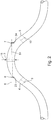
- FIG. 1 an inventive measuring tube 3 of a measuring system 1 according to the invention is shown schematically in section.
- the measuring tube 3 has in each case a first measuring tube inlet 4 and a first measuring tube outlet 5.
- the measuring tube inlet 4 has a cross section approximately constant over its length. This is in this embodiment approximately equal to the cross section of the measuring tube 3, both in shape and in size.
- the measuring tube outlet 5, however, is slightly conical, so that the cross section of the measuring tube outlet 5, which adjoins the measuring tube, is slightly larger than the cross section of the measuring tube outlet 5, which can be used as a process connection.
- Both the measuring tube axis 8, and the measuring tube inlet axis 9 and the measuring tube outlet axis 10 lie in a spatial plane, here the drawing plane, wherein the measuring tube inlet 4 and the measuring tube outlet 5 are arranged on opposite sides of the measuring tube 3.
- Disc-shaped electromechanical transducer elements 6 and 7, for converting electrical signals into ultrasonic signals and / or vice versa, are acoustically coupled to ultrasonic transducer receptacles 23 and 24.
- the ultrasonic transducer receptacles 23 and 24 have a substantially cylindrical shape. They assume the function of coupling the ultrasonic signals into the measuring medium 2.
- the ultrasonic signals from the electromechanical Transducer elements 6, 7 generates and coupled to the transducer receiving surfaces in the Ultraschallwandleraidn 23 and 24, which in turn direct the ultrasonic signals to the measuring medium 2 and via their sound input and sound output surfaces 16 and 17 couple the ultrasonic signals in the measuring medium 2.
- the ultrasound signals are guided by the measuring medium 2 back to the electromechanical transducer elements, they are coupled out of the measuring medium 2 at the sound in or sound outcoupling surfaces 16 and 17 and guided by the ultrasound transducer receptacles 23 and 24 up to the electromechanical transducer elements 6, 7.
- the sound input or sound output surfaces 16 and 17 are smaller here than the surfaces of the electromechanical transducer elements 6, 7.
- the ultrasound transducer recordings 23 and 24 have the shape of an exponential horn, at least in the area of the sound in or sound outcoupling surfaces 16 and 17.
- the ultrasonic signals propagate along a so-called signal or measurement path. A straight-line measuring path is modeled here.
- the wavefronts of the ultrasonic signal are substantially perpendicular to the measurement path.
- Both the sound in or sound outcoupling surfaces 16 and 17, and the electromechanical transducer elements 6, 7 and the transducer receiving surfaces of the ultrasonic transducer receptacles 23 and 24 have a substantially circular cross-section.
- the midpoints 27, 28 of the sound in or Schallauskoppel inhabit 16 and 17 and the centers of the electromechanical transducer elements 6, 7 and the transducer receiving surfaces of the Ultraschallwandler techniquen 23 and 24 are on a single straight.
- the measurement path is considered to coincide with the connecting line 11 between the centers 12 and 13 of the electromechanical transducer elements 6, 7 and thus the angle ⁇ between the connecting line 11 between the centers 12 and 13 of the first and second electromechanical transducer element 6, 7 and between the measuring tube axis 8 and the angle ⁇ between the connecting line between the centers of the sound in and / or Schallauskoppel inhabit 16, 17 and the measuring tube axis 8 and the angle ⁇ between the connecting line between the centers of the wall and the measuring tube axis 8 equal and equal to the angle ⁇ of the measuring path.
- the measuring path or signal path which here is equal to the connecting line 11 between the centers 12 and 13 of the electromechanical transducer elements 6, 7, is slightly inclined to the measuring tube axis 8.
- the angle ⁇ or ⁇ here is about 5 °.
- the measuring path 11 extends completely on the side of the measuring tube axis 8, on which the measuring tube outlet 5 is located.
- a first imaginary room level is, as already described, spanned by the measuring tube axis 8 and the measuring tube inlet and measuring tube outlet axes 9 and 10.
- a second imaginary plane is then perpendicular to the first imaginary plane and intersects the first imaginary plane in a first cut line. In this embodiment, this first cutting line is the measuring tube axis 8 itself.
- the connecting line between the centers of the sound inlet and / or sound output surfaces 16, 17 or here the measuring path does not intersect the second imaginary plane.
- the measuring path 11 is located on the side of the second imaginary plane, on which the measuring tube outlet 5 is also arranged on the measuring tube 3.
- the surfaces of the electromechanical transducer element 6, 7, the transducer mounting surfaces and in particular the sound input and / or sound output surfaces 16, 17 are smaller than the free cross section of the measuring tube 3, which here is derivable from the inner diameter of the measuring tube 3.
- Fig. 2 discloses a measuring system 1 according to the invention with a further measuring tube 3 according to the invention.
- the measuring tube 3 has an approximately circular cross-section and a short longitudinal extent relative to its diameter.
- the measuring tube inlet 4 and the measuring tube outlet 5 have approximately the same and circular cross-sections. Again, these are short relative to their cross sections.
- the measuring tube inlet 4 and the measuring tube outlet 5 do not directly adjoin the measuring tube 3. However, they are each connected to it via an intermediate tube 73, 74.
- the intermediate tubes 73, 74 are curved and / or bent. A definition of straight axes in the intermediate tubes 73, 74 is therefore not easily possible.
- Both the measuring tube 3, as well as the measuring tube inlet 4 and the measuring tube outlet 5, here have a certain length with a straight central axis 8, 9, 10, on which all centers of the respective tube 3, 4, 5 lie.
- the measuring tube outlet axis 10 and measuring tube axis 8 span a first imaginary plane, that is to say both the measuring tube outlet axis 10 and the measuring tube axis 8 lie in the first imaginary plane, here the drawing plane. Perpendicular to this first imaginary plane extends a second imaginary plane, wherein the measuring tube axis 8 lies in this second imaginary plane, the measuring tube axis 8 is thus part of the first line of intersection between the first and second imaginary plane.
- the connecting line between the center points of the first and second electromechanical transducer elements 6 and 7, which face one another in a plane-parallel manner, which here equals equal to the inscribed measuring path, now runs on the side of the measuring tube outlet and does not intersect the second level.
- the measuring path lies in an imaginary third plane which, in parallel with the second imaginary plane, bisects the inner diameter 15 of the measuring tube 3.
- the propagation of the ultrasonic waves generated by the electromechanical transducer elements 6 and 7, the measured transit time difference in and against the flow of the measuring medium in the measuring tube 3 is included in the calculation of the flow.
- the measuring path 54 is arranged in a region of the measuring tube 3, where a flow profile known by calibration is present due to the particular shape of the measuring tube 3, the measuring path 54 is e.g. In a flow which is accelerated in comparison with the flow prevailing in the region of the measuring tube axis, the quality of the measurement or determination of the flow, in particular for viscous measuring media or altogether very slow flows and / or flow rates, is increased.
- Fig. 3 shows a further inventive measuring tube 3 of a measuring system 1 according to the invention schematically shown in section. It has essentially the same cross sections of the measuring tube inlet 4 and outlet 5 and of the measuring tube 3. Both the measuring tube inlet 4, and the measuring tube outlet 5 have an angle of approximately 45 ° to the measuring tube axis, so ⁇ ⁇ ⁇ ⁇ 45 °. Furthermore, the measuring tube 3 has four ultrasonic transducer receptacles 23, 24, 45, 46. The Ultraschallwandleringn 23, 24, 45, 46 are each designed cup-shaped. Electromechanical transducer elements 6, 7, 19, 20 can be introduced into the cup-shaped ultrasonic transducer receptacles 23, 24, 45, 46.
- the ultrasonic transducer receptacles 23, 24, 45, 46 then serve as coupling elements between the electromechanical transducer elements 6, 7, 19, 20 and the measuring medium 2 in the measuring tube 3.
- the electromechanical transducer elements 6, 7, 19, 20 are connected to the transducer mounting surfaces 29, 30, 52, 53 of the ultrasonic transducer recording 23, 24, 45, 46 acoustically coupled.
- the transducer receiving surfaces 29, 30, 52, 53 equally represent the cup inner bottoms of the cup-shaped ultrasonic transducer receptacles 23, 24, 45, 46.
- this angle ⁇ is 0 ° or 180 °, ie the connecting line 26 and measuring tube axis 8 are parallel to one another.
- the four ultrasonic transducer holders 23, 24, 45, 46 lie opposite each other in pairs, the first and the third ultrasonic transducer holders 23, 45 lying in the region of the measuring tube inlet 4 and the second and fourth ultrasonic transducer holders 24, 46 being arranged in the region of the measuring tube outlet 5.
- Both measuring paths are parallel to the measuring tube axis 8, i.
- both the electromechanical transducer elements 6, 7, 19, 20 and the sound coupling and / or sound output surfaces 16, 17, 47, 48 are substantially smaller than the measuring tube diameter 15th
- the measuring tube 8 divides the cross section of the inner diameter 15 of the measuring tube 3 into two equal parts. As also easily recognizable, this divided inner diameter 15 is in turn divided by the first measuring path 54.
- the opposite Schalleinkoppel- and / or Schallauskoppel lake 16 and 17 are completely and clearly on the side of the measuring tube axis 8, on which the measuring tube outlet 5 is located. Therefore, the first measuring path 54 is also clearly beyond a line which third the inner diameter 15 of the measuring tube 3.
- the first measuring path 15 is even on the side of a so-called quarter plane, ie a plane parallel to a second imaginary space plane, which quarter plane the inner diameter 15 of the measuring tube 3 quarters, on which side of the imaginary quarter plane and the measuring tube outlet 5 is arranged, the second imaginary spatial plane is perpendicular to a first spatial plane, with the measuring tube axis 8 as a cutting line between the first and second spatial plane, which first spatial plane of the measuring tube axis 8 and the measuring tube outlet 5 is spanned.
- quarter plane ie a plane parallel to a second imaginary space plane, which quarter plane the inner diameter 15 of the measuring tube 3 quarters, on which side of the imaginary quarter plane and the measuring tube outlet 5 is arranged
- the second imaginary spatial plane is perpendicular to a first spatial plane, with the measuring tube axis 8 as a cutting line between the first and second spatial plane, which first spatial plane of the measuring tube axis 8 and the measuring tube outlet 5 is spanned.
- the measuring tube 3 has on its inside two rings 14, which reduce the free cross section of the measuring tube 3.
- the rings protrude 1/10 of the inside diameter of the measuring tube into the measuring tube. Every ring has a distance of the measuring tube inlet 4 and / or outlet 5 closest to it from 0 to 1/2 of the measuring tube length to one another. Through the rings, a linearization of the measurement characteristic is achieved, but at the same time requires a change in the algorithm for Reynoldswasbetician.
- Fig. 4 are different coupling elements drawn in cross section.
- the signal energy of the electromechanical transducer element 6 is bundled. This is advantageous for the emission of ultrasound signals.
- the enlargement of the cross-sectional area from the transducer receiving surface 29 to the sound input and / or sound output surface 16 acts as a funnel for incoming ultrasonic signals. Your signal energy is in turn bundled before hitting the electromechanical transducer element 6.
- the directivity and the sensitivity / radiation power is optimized by the various coupling elements to their respective application.
- the coupling elements take on different shapes. Shown is only a selection without claim to completeness. In addition to the gradation of the coupling element and coupling elements in the form of a truncated cone or an exponential horn are shown. It is also conceivable a system of acoustic lenses.
- Fig. 5 3 schematically outlines an inventive measuring system 1.
- the measuring system comprises a base plate 62, with a coupling, not shown, for fixing the measuring tube 3.
- the measuring tube 3 in turn has a suitable for coupling the base plate 62 plug 43.
- the measuring tube 3 is detachably connected to the base plate 62 and secured against rotation and displacement. Only by unplugging the measuring tube 3 can be moved relative to the base plate 62.
- the measuring tube 3 has a measuring tube inlet 4 and a measuring tube outlet 5, which lie here in a spatial plane.
- the measuring system 1 comprises a first ultrasonic transducer 58 and a second ultrasonic transducer 59.
- the second ultrasonic transducer 59 is in this embodiment, similar to the measuring tube 3, plugged onto the base plate 62 and detachably connected thereto.
- the second ultrasonic transducer 59 is only by unplugging relative to the base plate 62 to move.
- the first ultrasonic transducer 58 is mounted coaxially to the measuring tube axis displaceable on the base plate 62. He has a first, not embodied here, guide element, which together with a second guide member 68 of the Base plate 62 ensures the displacement of the first ultrasonic transducer 58.
- the second guide member 68 is a T-groove.
- An attached to the first ultrasonic transducer 58 and appropriately designed rail allows the positive connection of the first ultrasonic transducer 58 and base plate 62 with simultaneous degree of freedom of the first ultrasonic transducer 58 coaxial with the measuring tube axis.
- the first ultrasonic transducer 58 is pushed for mounting on the measuring tube 3 and coupled acoustically by moving the first bracket 56 to the measuring tube 3.
- Both the first ultrasonic transducer 58 has a first bracket 56
- the second ultrasonic transducer 59 has a second bracket 57.
- the brackets 56, 57 are designed so that they hook into the arranged on the measuring tube 3 and the ultrasonic transducer receptacles 23, 24 pins 39, 40, 41 in the folded state and thus the ultrasonic transducers 58 and 59 on the measuring tube 3 releasably secure.
- One possible embodiment of the mechanics of attachment is in the Fig. 8a and 8b presents.
- the brackets 56, 57 are folded over and the ultrasonic transducers 58 and 59 are mounted or released again from the measuring tube.
- Fig. 5 shows the ultrasonic transducer 58 and 59 in the assembled state and thus the bracket 56 and 57 in the folded or closed state.
- the clamping brackets 75 and 76 serve here simultaneously as securing bracket or locking lever.
- the Fig. 6a and 6b describe the measuring tube 3 with a measuring tube inlet 4 and a measuring tube outlet 5, as in Fig. 5 is still shown mounted on the base plate.
- feet 43 are provided for docking the measuring tube 3 on a base plate on the measuring tube 3 and the pins 39, 40, 41 for coupling ultrasonic transducers. On the feet 43, the measuring tube 3 is merely supported on the base plate. The base plate in this case would not have a coupling.
- the measuring tube 3 is not connectable to the base plate here and only held in position via the ultrasonic transducers. However, supporting the measuring tube on the baseplate can be very useful during installation.
- the first ultrasonic transducer holder 23 is designed cup-shaped. A first transducer receiving surface 29 forms the bottom of the pot of the ultrasonic transducer recording 23. At this first transducer receiving surface 29, the first electromechanical transducer element 6 is acoustically coupled directly or indirectly via a first coupling element of the first ultrasonic transducer.
- the first ultrasonic transducer holder 23 has guide rails 77. These serve here for alignment and guidance of the first ultrasonic transducer coaxial with the measuring tube axis.
- Fig. 7 shows a cross section through an inventive measuring system 1 with a measuring tube according to the invention a first ultrasonic transducer 58 and a base plate 62.
- the first ultrasonic transducer 58 has a first electromechanical transducer element 6, by means of which received ultrasonic signals are converted into electrical signals or which converts electrical signals into ultrasonic signals.
- the first electromechanical transducer element 6 is arranged at the tip of a so-called sensor cup 71.
- the sensor cup 71 is guided in the first ultrasonic transducer holder 23.
- the first electromechanical transducer element 6 is in approximately acoustically gapless contact with the first transducer receiving surface 29 of the first ultrasonic transducer holder 23.
- the centers of the first transducer receiving surface 29 of the first ultrasonic transducer holder 23 and the first electromechanical transducer element 6 lie on an axis which axis is equal to the connecting line between the centers the first sound input and / or sound output surface 16 of the first ultrasonic transducer recording 23 and the second sound input and / or sound output surface of the second ultrasonic transducer recording and thus is equal to the first measuring path.
- the first ultrasonic transducer holder 23 is shown cup-shaped with the first transducer receiving surface 29 as a pot bottom.
- the spring force of the coil spring 69 is in turn dependent, inter alia, on the position of the first ultrasonic transducer 58 relative to the first transducer receiving surface 29. This is in the assembled state, so if the bracket 56 are folded, by moving the first clamping bracket, here a clamping lever 75, and have intervened in the pin on the measuring tube, only affected by manufacturing tolerances of the individual components. Adjusting this spring force by means of an adjusting screw 78.
- the adjusting screw 78 is connected to the housing 70 of the first ultrasonic transducer 58 and the coil spring 69 rests on the one hand on the adjusting screw 78 and on the other hand on the sensor cup 71.
- By adjusting screw 78 is a predetermined force the first electromechanical transducer element 6 or on the first transducer receiving surface 29 adjustable.
- first and a second guide element which are arranged on the first ultrasonic transducer 58 and the base plate 62.
- a relative movement of the first ultrasonic transducer 58 to the base plate 62 is only possible in the assembled state to the extent of the depression of the spring 69.
- a stop on the ultrasonic transducer is provided, which prevents further depression of the spring 69 when the clamping lever 75 is folded over.
- the tasks and functions of the first and second guide element, so the so-called linear guide of the ultrasonic transducer 58 on the base plate 62 are distributed in this embodiment on a cylindrical pin 80 which is firmly anchored in the base plate 62, and a guide track 67 in the ultrasonic transducer.
- a screw in a spacer sleeve 81 is capable of relative movement coaxially with the measuring path to a limited extent.
- the spacer sleeve 81 allows small movements of the ultrasonic transducers 58 in both directions in the plane parallel to the base plate. The goal is that the ultrasonic transducers 58 are aligned exclusively by the ultrasonic transducer receptacles 23 on the measuring tube 3 and not by the guide track 67 as the first guide element on the base plate.
- Fig. 8a and 8b is a mechanism for mounting the ultrasonic transducer on the measuring tube illustrated.
- the first ultrasonic transducer 58 is in Fig. 8a with closed fastening mechanism, ie with folded bracket, and in Fig. 8b to see with open temple. It can be seen the first electromechanical transducer element 6 of the ultrasonic transducer 58, which is pressed against the transducer receiving surface, not shown, of the measuring tube in the mounted state.
- the cables are guided under the base plate.
- a first axis 83 connects the first bracket 56 and the first bracket 75 in the manner shown.
- the second axis 84 only the clamping bracket 75 is attached to the ultrasonic transducer 58. This results in the folding of the tensioning bow 75, a rotational and translational movement of the first bracket 56. This is again designed so that it can hook into the pins of the measuring tube and thus detects the ultrasonic transducer on the measuring tube.
- Fig. 9 is the previously described base plate 62 drawn in a plan view. To see a cable channel on the underside of the base plate 62, ie on the side facing away from the measuring tube of the base plate, in which the cables 72 of the ultrasonic transducers are hidden in the base plate 62 and protected from external influences. The cables 72 are guided by an angle plug 82 of the ultrasonic transducers on the underside of the base plate 62.
- the measuring tube 3 has a first measuring tube inlet 4 and a first measuring tube outlet 5 which are arranged at an angle of approximately 45 ° to the measuring tube 3 on the measuring tube 3, ie the first measuring tube inlet axis 9 and the first measuring tube outlet axis 10 each have an angle of approximately 45 ° to the measuring tube axis 8.
- First measuring tube inlet 4 and first measuring tube outlet 5 lie on opposite sides of the measuring tube 3, ie the first one
- the measuring tube inlet axis 9 and the first measuring tube outlet axis 10 are parallel to one another and lie substantially in one spatial plane.
- the measuring tube 3 now has an additional inlet section or an additional, second measuring tube inlet 34 and an additional outlet section or an additional, second measuring tube outlet 35, which in turn each have a central axis 36, 37.
- the second measuring tube inlet 34 adjoins the first measuring tube inlet 4 and the second measuring tube outlet 35 adjoins the first measuring tube outlet 5.
- the second measuring tube inlet axis 36 in this exemplary embodiment has an angle of substantially 90 ° to the measuring tube axis and the second measuring tube outlet axis 37 likewise has one here Angle of substantially 90 ° to the measuring tube axis.
- the second measuring tube inlet axis 36 and the second measuring tube outlet axis 37 are also in the same spatial plane as the first measuring tube inlet axis 9 and the first measuring tube outlet axis 10 and the measuring tube axis 8.
- the flow of the measuring medium in the measuring tube 3 is conditioned in a predefined manner.
Landscapes
- Physics & Mathematics (AREA)
- Electromagnetism (AREA)
- Fluid Mechanics (AREA)
- General Physics & Mathematics (AREA)
- Measuring Volume Flow (AREA)
Claims (11)
- Système de mesure (1) destiné à la détermination et/ou la surveillance du débit d'un produit mesuré (2) à travers un tube de mesure (3), le système de mesure comprenant le tube de mesure et un premier convertisseur à ultrasons (6) et au moins un deuxième convertisseur à ultrasons (7), le tube de mesure (3) présentant un entrée de tube de mesure (4) et une sortie de tube de mesure (5) et un premier support de convertisseur à ultrasons (29) et au moins un autre, deuxième support de convertisseur à ultrasons (30), le premier convertisseur à ultrasons (6) pouvant être couplé de façon acoustique, de façon amovible, avec le premier support de convertisseur à ultrasons (29) du tube de mesure (3) et le deuxième convertisseur à ultrasons (7) pouvant être couplé de façon acoustique, de façon amovible, avec le deuxième support de convertisseur à ultrasons (30) du tube de mesure (3),
caractérisé
en ce qu'au moins un convertisseur à ultrasons (58, 59, 60, 61) comporte au moins un étrier (56, 57), lequel étrier (56, 57) peut être replié et est conçu de telle sorte que l'étrier (56, 57) peut être engagé dans au moins une saillie ou un creux (39, 40, 41, 42) disposé sur le tube de mesure (3), et
en ce que le convertisseur à ultrasons (58, 59, 60, 61) peut être monté de façon amovible sur le tube de mesure (3) et peut être couplé de façon acoustique avec le support de convertisseur à ultrasons (29, 30) du tube de mesure (3). - Système de mesure selon la revendication 1,
caractérisé
en ce qu'au moins un convertisseur à ultrasons (58, 59, 60, 61) comporte au minimum un premier élément de guidage (67) destiné au guidage du convertisseur à ultrasons (58, 59, 60, 61) sur une plaque de base (62), et en ce que la plaque de base (62) comporte au minimum un deuxième élément de guidage (68) - conçu de façon analogue / adapté au premier élément de guidage (67) - destiné au guidage du convertisseur à ultrasons (58, 59, 60, 61) sur la plaque de base (62), le premier élément de guidage (67) et le deuxième élément de guidage (68) faisant chacun partie d'un guidage linéaire. - Système de mesure selon la revendication 2,
caractérisé
en ce que le tube de mesure (3) comporte au moins un connecteur mâle (43) ou au moins un connecteur femelle pour la constitution d'une connexion enfichable entre le tube de mesure (3) et la plaque de base (62) sur le côté extérieur de tube de mesure (38), et la plaque de base (62) comporte de façon analogue au moins un connecteur mâle ou au moins un connecteur femelle (44) pour la constitution d'une connexion enfichable entre le tube de mesure (3) et la plaque de base (62). - Système de mesure selon l'une des revendications 1 à 3,
caractérisé
en ce que les saillies ou les creux (39, 40, 41, 42) sont disposés dans la zone des supports de convertisseur à ultrasons (29, 30) sur le tube de mesure (3). - Système de mesure selon l'une des revendications 1 à 4,
caractérisé
en ce que les convertisseurs à ultrasons (58, 59, 60, 61) comportent chacun au moins un élément convertisseur électromécanique (6, 7, 19, 20) ou chacun au moins un élément convertisseur électromécanique (6, 7, 19, 20) et chacun au moins un élément de couplage (63, 64, 65, 66), lesquels éléments de couplage (63, 64, 65, 66) sont disposés à l'état monté des convertisseurs à ultrasons (58, 59, 60, 61) entre les éléments convertisseurs électromécaniques (6, 7, 19, 20) des convertisseurs à ultrasons (58, 59, 60, 61) et les supports de convertisseur à ultrasons (29, 30, 45, 46) du tube de mesure (3), lesquels éléments convertisseurs électromécaniques (6, 7, 19, 20) ou lesquels éléments de couplage (63, 64, 65, 66) peuvent être couplés au moyen d'une force définissable avec les supports de convertisseur à ultrasons (29, 30, 45, 46) du tube de mesure (3). - Système de mesure selon la revendication 5,
caractérisé
en ce que la force peut être appliquée au moyen d'un ressort (69) entre un boîtier de convertisseur à ultrasons (70) et une cuvette de capteur (71), l'élément convertisseur électromécanique (6, 7, 19, 20) étant disposé sur la cuvette de capteur (71). - Système de mesure selon l'une des revendications 1 à 6,
caractérisé
en ce que les supports de convertisseur à ultrasons (29, 30 45, 46) sont disposés dans la zone de l'entrée de tube de mesure (4) et/ou dans la zone de la sortie de tube de mesure (5). - Système de mesure selon l'une des revendications 1 à 7,
caractérisé
en ce que les supports de convertisseur à ultrasons (23, 24 45, 46) sont conçus en forme de pot, avec la surface de support de convertisseur (29, 30, 52, 53) respective du support de convertisseur à ultrasons (23, 24 45, 46) comme fond de pot, et les composants des convertisseurs à ultrasons (58, 59, 60, 61), lesquels peuvent être introduits dans les supports de convertisseur à ultrasons (23, 24, 45, 46) en forme de pot, présentent une taille légèrement plus petite. - Système de mesure selon l'une des revendications 1 à 8,
caractérisé
en ce que les convertisseurs à ultrasons (58, 59, 60, 61) comportent chacun au moins un élément convertisseur électromécanique (6, 7, 19, 20), le tube de mesure (3) avec les supports de convertisseur à ultrasons (29, 30, 45, 46) étant conçu de telle sorte que les éléments convertisseurs (6, 7, 19, 20) se font face dans des plans parallèles, pour l'essentiel par paires, à l'état monté des convertisseurs à ultrasons (58, 59, 60, 61). - Système de mesure selon l'une des revendications 1 à 9,
caractérisé
en ce que les convertisseurs à ultrasons (58, 59, 60, 61) comportent chacun au moins deux éléments convertisseurs électromécaniques (6, 7, 19, 20). - Système de mesure selon l'une des revendications 1 à 10,
caractérisé
en ce que la plaque de base (62) est conçue de telle sorte que les câbles (72) des convertisseurs à ultrasons (58, 59, 60, 61) sont recouverts sur ou dans la plaque de base, ou posés de manière à être protégés contre les influences extérieures.
Applications Claiming Priority (2)
| Application Number | Priority Date | Filing Date | Title |
|---|---|---|---|
| DE102008055167A DE102008055167A1 (de) | 2008-12-29 | 2008-12-29 | Messsystem zur Bestimmung und/oder Überwachung des Durchflusses eines Messmediums durch das Messrohr mittels Ultraschall |
| PCT/EP2009/066914 WO2010076153A1 (fr) | 2008-12-29 | 2009-12-11 | Système de mesure pour déterminer et/ou surveiller par ultrasons le débit d'un milieu de mesure dans le tube de mesure |
Publications (2)
| Publication Number | Publication Date |
|---|---|
| EP2370795A1 EP2370795A1 (fr) | 2011-10-05 |
| EP2370795B1 true EP2370795B1 (fr) | 2019-04-10 |
Family
ID=41621060
Family Applications (1)
| Application Number | Title | Priority Date | Filing Date |
|---|---|---|---|
| EP09774894.1A Not-in-force EP2370795B1 (fr) | 2008-12-29 | 2009-12-11 | Système de mesure pour déterminer et/ou surveiller par ultrasons le débit d'un milieu de mesure dans le tube de mesure |
Country Status (4)
| Country | Link |
|---|---|
| US (1) | US8904878B2 (fr) |
| EP (1) | EP2370795B1 (fr) |
| DE (1) | DE102008055167A1 (fr) |
| WO (1) | WO2010076153A1 (fr) |
Cited By (1)
| Publication number | Priority date | Publication date | Assignee | Title |
|---|---|---|---|---|
| EP4528233A1 (fr) * | 2023-09-22 | 2025-03-26 | Krohne AG | Débitmètre à ultrasons et agencement de mesure |
Families Citing this family (19)
| Publication number | Priority date | Publication date | Assignee | Title |
|---|---|---|---|---|
| DE102008055164A1 (de) * | 2008-12-29 | 2010-07-01 | Endress + Hauser Flowtec Ag | Messsystem zur Bestimmung und/oder Überwachung des Durchflusses eines Messmediums durch das Messrohr mittels Ultraschall |
| DE102012200757B4 (de) * | 2012-01-05 | 2022-01-05 | Vitesco Technologies GmbH | Füllstandsgeber |
| GB2504288A (en) * | 2012-07-24 | 2014-01-29 | Titan Entpr Ltd | Acoustic flow meter |
| US9928724B2 (en) | 2015-05-13 | 2018-03-27 | Rachio, Inc. | Flow characteristic detection and automatic flow shutoff |
| US9671270B2 (en) * | 2015-07-30 | 2017-06-06 | Daniel Measurement And Control, Inc. | Flow meter having electronic mount bracket assembly |
| DE112015002083B4 (de) * | 2015-08-20 | 2020-03-19 | Honda Electronics Co. Ltd. | Sensorklemmvorrichtung und Aufklemm-Ultraschalldurchflussmesser |
| CN108025130B (zh) | 2015-08-28 | 2021-02-19 | 克里斯医疗系统股份有限公司 | 具有连接组件的流量传感器系统 |
| CA3061509C (fr) | 2015-08-28 | 2022-06-21 | Crisi Medical Systems, Inc. | Systeme de capteur d'ecoulement avec absorbeur |
| JP6629963B2 (ja) | 2015-08-28 | 2020-01-15 | クリシー メディカル システムズ インコーポレイテッド | 伝達接続を含むフローセンサシステム |
| EP3673936B1 (fr) | 2015-08-28 | 2023-10-11 | Crisi Medical Systems, Inc. | Système de détecteur de débit comprenant des contacts de ressort |
| CN116688285B (zh) | 2016-06-17 | 2026-03-17 | 贝克顿·迪金森公司 | 用于润湿流体端口的内部流体路径表面以增进超声信号传输的方法和设备 |
| DE102016115199B4 (de) * | 2016-08-16 | 2023-08-31 | Endress+Hauser Flowtec Ag | Ultraschallsensor zur Bestimmung oder Überwachung einer Prozessgröße eines Mediums in der Automatisierungstechnik |
| CN110891633B (zh) | 2017-06-19 | 2022-04-01 | 贝克顿·迪金森公司 | 用以诱发适当压力和流量曲线并改善传感器准备状态的起动阀 |
| DE202017106804U1 (de) * | 2017-11-09 | 2017-11-17 | Hegewald Medizinprodukte Gmbh | Messeinrichtung zur Bestimmung des Durchflusses von Flüssigkeiten zur parenteralen Ernährung, der Pharmazie oder der Biotechnologie oder von Blut oder Blutbestandteilen |
| JP6912097B2 (ja) * | 2017-11-17 | 2021-07-28 | 本多電子株式会社 | 超音波流量計 |
| JP2021532375A (ja) | 2018-07-06 | 2021-11-25 | ベクトン・ディキンソン・アンド・カンパニーBecton, Dickinson And Company | 流量センサおよび流体流測定を調整するための方法 |
| JP6603842B1 (ja) * | 2019-01-15 | 2019-11-13 | 本多電子株式会社 | 超音波流量計用の流量計測管、流量計測管付き輸液チューブ、超音波流量計測システム |
| AU2021210902B2 (en) | 2020-01-22 | 2026-03-05 | Becton, Dickinson And Company | Apparatus and method to join a coupler and flow tube in an ultrasonic flow meter |
| KR102189806B1 (ko) * | 2020-04-03 | 2020-12-11 | 김영탁 | 초음파 수도미터기 |
Citations (1)
| Publication number | Priority date | Publication date | Assignee | Title |
|---|---|---|---|---|
| FR2827321A1 (fr) * | 2001-07-10 | 2003-01-17 | Seperef | Systeme de connexion d'un ensemble traverse par un fluide a des conduites vehiculant ce fluide |
Family Cites Families (31)
| Publication number | Priority date | Publication date | Assignee | Title |
|---|---|---|---|---|
| EP0036658B1 (fr) * | 1980-03-25 | 1985-01-23 | Fuji Electric Co. Ltd. | Dispositif à ultrasons pour mesurer le débit d'un fluide dans un conduit |
| FI67627C (fi) | 1981-10-19 | 1985-04-10 | Eino Haerkoenen | Foerfarande och anordning foer maetning av stroemningshastigheten i stroemmen av uppslamningar genom utnyttjandet av ultraljud |
| US4598593A (en) | 1984-05-14 | 1986-07-08 | The United States Of America As Represented By The United States Department Of Energy | Acoustic cross-correlation flowmeter for solid-gas flow |
| FR2598498B1 (fr) * | 1985-03-15 | 1990-01-05 | Framatome Sa | Capteur pour ondes ultrasonores destine a venir en contact avec une paroi a haute temperature et application de ce capteur |
| JPH0778438B2 (ja) | 1988-07-08 | 1995-08-23 | エンドレス ウント ハウザー フローテック アクチエンゲゼルシヤフト | 超音波流量測定方法及び装置 |
| US5179862A (en) | 1990-06-29 | 1993-01-19 | Panametrics, Inc. | Snap-on flow measurement system |
| WO1995017650A1 (fr) | 1993-12-23 | 1995-06-29 | Endress + Hauser Flowtec Ag | Appareil verrouillable de mesure par ultrasons du debit volumique |
| US5463906A (en) | 1994-01-24 | 1995-11-07 | Triton Technology, Inc. | Interchangeable disposable acoustic for use with an ultrasonic flowmeter, particularly during extracorporeal measurement of blood flow |
| JP3246851B2 (ja) | 1995-04-10 | 2002-01-15 | 東京計装株式会社 | 超音波流量計用検出器 |
| ES2296300T3 (es) * | 1996-06-12 | 2008-04-16 | Racine Federated Inc. | Caudalimetro de vortice ultrasonico que tiene procesado de señales a distancia. |
| US6142008A (en) * | 1998-06-12 | 2000-11-07 | Abbott Laboratories | Air bubble sensor |
| US6058779A (en) * | 1999-02-10 | 2000-05-09 | Cole; Mark S. | Coupled diaphragm interface for phacoemulsification apparatus |
| US6382029B1 (en) * | 2000-03-07 | 2002-05-07 | The United States Of America As Represented By The Secretary Of Commerce | Apparatus and method for utilizing electromagnetic acoustic transducers to non-destructively analyze in-service conductive materials |
| JP3935356B2 (ja) * | 2001-02-05 | 2007-06-20 | サーパス工業株式会社 | 超音波流量計 |
| EP1279368A3 (fr) * | 2001-07-17 | 2004-09-15 | ndd Medizintechnik AG | Dispositif pour mesurer la vitesse de circulation et/ou la masse molaire des gaz ou de mélanges gazeux |
| DE10348676A1 (de) * | 2003-10-15 | 2005-05-12 | Flowtec Ag | Vorrichtung zur Bestimmung und/oder Überwachung des Volumen- und/oder Massendurchflusses eines Mediums in einer Rohrleitung |
| US7096135B2 (en) * | 2004-03-12 | 2006-08-22 | Panametrics, Inc. | Method and system for calculating the transit time of an ultrasonic pulse |
| DE102004052489A1 (de) * | 2004-10-28 | 2006-05-18 | Endress + Hauser Flowtec Ag | Vorrichtung zum Befestigen eines Messsensors auf einer Rohrleitung |
| DE102005041288A1 (de) | 2005-08-31 | 2007-03-01 | GEMÜ Gebr. Müller Apparatebau GmbH & Co. KG | Durchflussmessgerät |
| DE102005052550B3 (de) * | 2005-11-02 | 2007-02-08 | Krohne Ag | Clamp-on-Meßgerät |
| US7247979B2 (en) * | 2005-11-07 | 2007-07-24 | Ge Security, Inc. | Device and apparatus for holding a transducer |
| JP4702668B2 (ja) | 2006-03-29 | 2011-06-15 | Smc株式会社 | 流量測定装置 |
| DE102006062706B4 (de) * | 2006-03-30 | 2012-12-06 | Krohne Ag | Ultraschalldurchflußmeßgerät |
| DE102006062705B4 (de) * | 2006-03-30 | 2015-07-30 | Krohne Ag | Ultraschalldurchflußmeßgerät |
| DE102006015217B4 (de) * | 2006-03-30 | 2008-01-24 | Krohne Ag | Ultraschalldurchflußmeßgerät |
| US20080236297A1 (en) * | 2007-01-23 | 2008-10-02 | Geoff Van Fleet | Acoustically compatible insert for an ultrasonic probe |
| GB0703250D0 (en) * | 2007-02-20 | 2007-03-28 | Ge Healthcare Bio Sciences Ab | Ultrasonic flow meter |
| DE102007023802A1 (de) * | 2007-05-21 | 2008-11-27 | Endress + Hauser Flowtec Ag | Clamp-On Durchflussmessgerät zur Befestigung an einer Rohrleitung |
| CH700433B1 (de) * | 2007-07-19 | 2010-08-31 | Aquametro Ag | Durchfluss-Messeinrichtung. |
| DE102008002027A1 (de) | 2008-05-28 | 2009-12-03 | Endress + Hauser Flowtec Ag | Messzelle, welche lösbar an einer dafür vorgesehenen Messvorrichtung anbringbar ist |
| JP6124410B2 (ja) * | 2011-03-18 | 2017-05-10 | ソネター, インク.Soneter, Inc. | 流体流測定方法および装置 |
-
2008
- 2008-12-29 DE DE102008055167A patent/DE102008055167A1/de not_active Withdrawn
-
2009
- 2009-12-11 US US13/142,618 patent/US8904878B2/en not_active Expired - Fee Related
- 2009-12-11 WO PCT/EP2009/066914 patent/WO2010076153A1/fr not_active Ceased
- 2009-12-11 EP EP09774894.1A patent/EP2370795B1/fr not_active Not-in-force
Patent Citations (1)
| Publication number | Priority date | Publication date | Assignee | Title |
|---|---|---|---|---|
| FR2827321A1 (fr) * | 2001-07-10 | 2003-01-17 | Seperef | Systeme de connexion d'un ensemble traverse par un fluide a des conduites vehiculant ce fluide |
Cited By (1)
| Publication number | Priority date | Publication date | Assignee | Title |
|---|---|---|---|---|
| EP4528233A1 (fr) * | 2023-09-22 | 2025-03-26 | Krohne AG | Débitmètre à ultrasons et agencement de mesure |
Also Published As
| Publication number | Publication date |
|---|---|
| EP2370795A1 (fr) | 2011-10-05 |
| US8904878B2 (en) | 2014-12-09 |
| US20120192656A1 (en) | 2012-08-02 |
| WO2010076153A1 (fr) | 2010-07-08 |
| DE102008055167A1 (de) | 2010-07-01 |
Similar Documents
| Publication | Publication Date | Title |
|---|---|---|
| EP2370795B1 (fr) | Système de mesure pour déterminer et/ou surveiller par ultrasons le débit d'un milieu de mesure dans le tube de mesure | |
| EP2370793B1 (fr) | Système de mesure pour déterminer et/ou surveiller par ultrasons le débit d'un milieu de mesure dans le tube de mesure | |
| EP2370794B1 (fr) | Tube de mesure d'un système de mesure pour déterminer et/ou surveiller le débit d'un fluide à mesurer à travers le tube de mesure à l'aide d'ultrasons | |
| DE102007013176B4 (de) | Durchflussratenmessvorrichtung | |
| EP2300786B1 (fr) | Capteur ultrasonique d'un système de mesure permettant la détermination et/ou la surveillance du débit d'un milieu de mesure à travers un tube de mesure | |
| EP1554549B1 (fr) | Débitmètre | |
| EP1993742B1 (fr) | Dispositif pour déterminer et/ou surveiller le débit volumique ou massique d'une substance dans une conduite tubulaire | |
| EP0644999B1 (fr) | Indicateur de niveau | |
| DE102014107697A1 (de) | Ultraschallströmungsmesser | |
| DE102007011546B4 (de) | Fluidzähler | |
| DE102008029772A1 (de) | Verfahren und Messsystem zur Bestimmung und/oder Überwachung des Durchflusses eines Messmediums durch ein Messrohr | |
| EP2300785A1 (fr) | Procédé et système de mesure permettant la détermination et/ou la surveillance du débit d'un milieu de mesure à travers un tube de mesure | |
| EP3404372B1 (fr) | Débitmètre ultrasonique | |
| EP3230696B1 (fr) | Débitmètre ultrasonique | |
| DE102007023802A1 (de) | Clamp-On Durchflussmessgerät zur Befestigung an einer Rohrleitung | |
| EP0763717A2 (fr) | Dispositif de mesure ultrasonique de débit | |
| DE202008002816U1 (de) | Vorrichtung zur Durchflussmessung | |
| EP3855134A1 (fr) | Dispositif de mesure du débit d'écoulement d'un fluide | |
| DE102008002027A1 (de) | Messzelle, welche lösbar an einer dafür vorgesehenen Messvorrichtung anbringbar ist | |
| EP3084363B1 (fr) | Dispositif de mesure et débitmètre à ultrasons | |
| EP2317288B1 (fr) | Dispositif de mesure de quantités de débit doté d'un miroir à l'extrémité du tube de mesure | |
| DE102016115199B4 (de) | Ultraschallsensor zur Bestimmung oder Überwachung einer Prozessgröße eines Mediums in der Automatisierungstechnik | |
| DE10109161B4 (de) | Durchflußmesser | |
| DE4341542C2 (de) | Durchflussmessvorrichtung | |
| WO2005031369A2 (fr) | Capteur a ultrasons, et procede pour mesurer des vitesses d'ecoulement |
Legal Events
| Date | Code | Title | Description |
|---|---|---|---|
| PUAI | Public reference made under article 153(3) epc to a published international application that has entered the european phase |
Free format text: ORIGINAL CODE: 0009012 |
|
| 17P | Request for examination filed |
Effective date: 20110512 |
|
| AK | Designated contracting states |
Kind code of ref document: A1 Designated state(s): AT BE BG CH CY CZ DE DK EE ES FI FR GB GR HR HU IE IS IT LI LT LU LV MC MK MT NL NO PL PT RO SE SI SK SM TR |
|
| DAX | Request for extension of the european patent (deleted) | ||
| STAA | Information on the status of an ep patent application or granted ep patent |
Free format text: STATUS: EXAMINATION IS IN PROGRESS |
|
| 17Q | First examination report despatched |
Effective date: 20180426 |
|
| GRAP | Despatch of communication of intention to grant a patent |
Free format text: ORIGINAL CODE: EPIDOSNIGR1 |
|
| STAA | Information on the status of an ep patent application or granted ep patent |
Free format text: STATUS: GRANT OF PATENT IS INTENDED |
|
| INTG | Intention to grant announced |
Effective date: 20181130 |
|
| RIN1 | Information on inventor provided before grant (corrected) |
Inventor name: BEZDEK, MICHAL Inventor name: WIEST, ACHIM |
|
| GRAS | Grant fee paid |
Free format text: ORIGINAL CODE: EPIDOSNIGR3 |
|
| GRAA | (expected) grant |
Free format text: ORIGINAL CODE: 0009210 |
|
| STAA | Information on the status of an ep patent application or granted ep patent |
Free format text: STATUS: THE PATENT HAS BEEN GRANTED |
|
| AK | Designated contracting states |
Kind code of ref document: B1 Designated state(s): AT BE BG CH CY CZ DE DK EE ES FI FR GB GR HR HU IE IS IT LI LT LU LV MC MK MT NL NO PL PT RO SE SI SK SM TR |
|
| REG | Reference to a national code |
Ref country code: GB Ref legal event code: FG4D Free format text: NOT ENGLISH |
|
| REG | Reference to a national code |
Ref country code: CH Ref legal event code: EP Ref country code: AT Ref legal event code: REF Ref document number: 1119319 Country of ref document: AT Kind code of ref document: T Effective date: 20190415 |
|
| REG | Reference to a national code |
Ref country code: IE Ref legal event code: FG4D Free format text: LANGUAGE OF EP DOCUMENT: GERMAN |
|
| REG | Reference to a national code |
Ref country code: DE Ref legal event code: R096 Ref document number: 502009015711 Country of ref document: DE |
|
| REG | Reference to a national code |
Ref country code: NL Ref legal event code: MP Effective date: 20190410 |
|
| REG | Reference to a national code |
Ref country code: LT Ref legal event code: MG4D |
|
| PG25 | Lapsed in a contracting state [announced via postgrant information from national office to epo] |
Ref country code: NL Free format text: LAPSE BECAUSE OF FAILURE TO SUBMIT A TRANSLATION OF THE DESCRIPTION OR TO PAY THE FEE WITHIN THE PRESCRIBED TIME-LIMIT Effective date: 20190410 |
|
| PG25 | Lapsed in a contracting state [announced via postgrant information from national office to epo] |
Ref country code: LT Free format text: LAPSE BECAUSE OF FAILURE TO SUBMIT A TRANSLATION OF THE DESCRIPTION OR TO PAY THE FEE WITHIN THE PRESCRIBED TIME-LIMIT Effective date: 20190410 Ref country code: HR Free format text: LAPSE BECAUSE OF FAILURE TO SUBMIT A TRANSLATION OF THE DESCRIPTION OR TO PAY THE FEE WITHIN THE PRESCRIBED TIME-LIMIT Effective date: 20190410 Ref country code: ES Free format text: LAPSE BECAUSE OF FAILURE TO SUBMIT A TRANSLATION OF THE DESCRIPTION OR TO PAY THE FEE WITHIN THE PRESCRIBED TIME-LIMIT Effective date: 20190410 Ref country code: FI Free format text: LAPSE BECAUSE OF FAILURE TO SUBMIT A TRANSLATION OF THE DESCRIPTION OR TO PAY THE FEE WITHIN THE PRESCRIBED TIME-LIMIT Effective date: 20190410 Ref country code: SE Free format text: LAPSE BECAUSE OF FAILURE TO SUBMIT A TRANSLATION OF THE DESCRIPTION OR TO PAY THE FEE WITHIN THE PRESCRIBED TIME-LIMIT Effective date: 20190410 Ref country code: NO Free format text: LAPSE BECAUSE OF FAILURE TO SUBMIT A TRANSLATION OF THE DESCRIPTION OR TO PAY THE FEE WITHIN THE PRESCRIBED TIME-LIMIT Effective date: 20190710 Ref country code: PT Free format text: LAPSE BECAUSE OF FAILURE TO SUBMIT A TRANSLATION OF THE DESCRIPTION OR TO PAY THE FEE WITHIN THE PRESCRIBED TIME-LIMIT Effective date: 20190910 |
|
| PG25 | Lapsed in a contracting state [announced via postgrant information from national office to epo] |
Ref country code: GR Free format text: LAPSE BECAUSE OF FAILURE TO SUBMIT A TRANSLATION OF THE DESCRIPTION OR TO PAY THE FEE WITHIN THE PRESCRIBED TIME-LIMIT Effective date: 20190711 Ref country code: PL Free format text: LAPSE BECAUSE OF FAILURE TO SUBMIT A TRANSLATION OF THE DESCRIPTION OR TO PAY THE FEE WITHIN THE PRESCRIBED TIME-LIMIT Effective date: 20190410 Ref country code: LV Free format text: LAPSE BECAUSE OF FAILURE TO SUBMIT A TRANSLATION OF THE DESCRIPTION OR TO PAY THE FEE WITHIN THE PRESCRIBED TIME-LIMIT Effective date: 20190410 Ref country code: BG Free format text: LAPSE BECAUSE OF FAILURE TO SUBMIT A TRANSLATION OF THE DESCRIPTION OR TO PAY THE FEE WITHIN THE PRESCRIBED TIME-LIMIT Effective date: 20190710 |
|
| PG25 | Lapsed in a contracting state [announced via postgrant information from national office to epo] |
Ref country code: IS Free format text: LAPSE BECAUSE OF FAILURE TO SUBMIT A TRANSLATION OF THE DESCRIPTION OR TO PAY THE FEE WITHIN THE PRESCRIBED TIME-LIMIT Effective date: 20190810 |
|
| REG | Reference to a national code |
Ref country code: DE Ref legal event code: R097 Ref document number: 502009015711 Country of ref document: DE |
|
| PG25 | Lapsed in a contracting state [announced via postgrant information from national office to epo] |
Ref country code: EE Free format text: LAPSE BECAUSE OF FAILURE TO SUBMIT A TRANSLATION OF THE DESCRIPTION OR TO PAY THE FEE WITHIN THE PRESCRIBED TIME-LIMIT Effective date: 20190410 Ref country code: SK Free format text: LAPSE BECAUSE OF FAILURE TO SUBMIT A TRANSLATION OF THE DESCRIPTION OR TO PAY THE FEE WITHIN THE PRESCRIBED TIME-LIMIT Effective date: 20190410 Ref country code: CZ Free format text: LAPSE BECAUSE OF FAILURE TO SUBMIT A TRANSLATION OF THE DESCRIPTION OR TO PAY THE FEE WITHIN THE PRESCRIBED TIME-LIMIT Effective date: 20190410 Ref country code: RO Free format text: LAPSE BECAUSE OF FAILURE TO SUBMIT A TRANSLATION OF THE DESCRIPTION OR TO PAY THE FEE WITHIN THE PRESCRIBED TIME-LIMIT Effective date: 20190410 Ref country code: DK Free format text: LAPSE BECAUSE OF FAILURE TO SUBMIT A TRANSLATION OF THE DESCRIPTION OR TO PAY THE FEE WITHIN THE PRESCRIBED TIME-LIMIT Effective date: 20190410 |
|
| PLBE | No opposition filed within time limit |
Free format text: ORIGINAL CODE: 0009261 |
|
| STAA | Information on the status of an ep patent application or granted ep patent |
Free format text: STATUS: NO OPPOSITION FILED WITHIN TIME LIMIT |
|
| PG25 | Lapsed in a contracting state [announced via postgrant information from national office to epo] |
Ref country code: SM Free format text: LAPSE BECAUSE OF FAILURE TO SUBMIT A TRANSLATION OF THE DESCRIPTION OR TO PAY THE FEE WITHIN THE PRESCRIBED TIME-LIMIT Effective date: 20190410 Ref country code: IT Free format text: LAPSE BECAUSE OF FAILURE TO SUBMIT A TRANSLATION OF THE DESCRIPTION OR TO PAY THE FEE WITHIN THE PRESCRIBED TIME-LIMIT Effective date: 20190410 |
|
| 26N | No opposition filed |
Effective date: 20200113 |
|
| PG25 | Lapsed in a contracting state [announced via postgrant information from national office to epo] |
Ref country code: TR Free format text: LAPSE BECAUSE OF FAILURE TO SUBMIT A TRANSLATION OF THE DESCRIPTION OR TO PAY THE FEE WITHIN THE PRESCRIBED TIME-LIMIT Effective date: 20190410 |
|
| PG25 | Lapsed in a contracting state [announced via postgrant information from national office to epo] |
Ref country code: SI Free format text: LAPSE BECAUSE OF FAILURE TO SUBMIT A TRANSLATION OF THE DESCRIPTION OR TO PAY THE FEE WITHIN THE PRESCRIBED TIME-LIMIT Effective date: 20190410 |
|
| REG | Reference to a national code |
Ref country code: CH Ref legal event code: PL |
|
| REG | Reference to a national code |
Ref country code: BE Ref legal event code: MM Effective date: 20191231 |
|
| PG25 | Lapsed in a contracting state [announced via postgrant information from national office to epo] |
Ref country code: MC Free format text: LAPSE BECAUSE OF FAILURE TO SUBMIT A TRANSLATION OF THE DESCRIPTION OR TO PAY THE FEE WITHIN THE PRESCRIBED TIME-LIMIT Effective date: 20190410 |
|
| GBPC | Gb: european patent ceased through non-payment of renewal fee |
Effective date: 20191211 |
|
| PG25 | Lapsed in a contracting state [announced via postgrant information from national office to epo] |
Ref country code: LU Free format text: LAPSE BECAUSE OF NON-PAYMENT OF DUE FEES Effective date: 20191211 Ref country code: IE Free format text: LAPSE BECAUSE OF NON-PAYMENT OF DUE FEES Effective date: 20191211 Ref country code: GB Free format text: LAPSE BECAUSE OF NON-PAYMENT OF DUE FEES Effective date: 20191211 Ref country code: FR Free format text: LAPSE BECAUSE OF NON-PAYMENT OF DUE FEES Effective date: 20191231 |
|
| PG25 | Lapsed in a contracting state [announced via postgrant information from national office to epo] |
Ref country code: BE Free format text: LAPSE BECAUSE OF NON-PAYMENT OF DUE FEES Effective date: 20191231 Ref country code: LI Free format text: LAPSE BECAUSE OF NON-PAYMENT OF DUE FEES Effective date: 20191231 Ref country code: CH Free format text: LAPSE BECAUSE OF NON-PAYMENT OF DUE FEES Effective date: 20191231 |
|
| PGFP | Annual fee paid to national office [announced via postgrant information from national office to epo] |
Ref country code: DE Payment date: 20201211 Year of fee payment: 12 |
|
| REG | Reference to a national code |
Ref country code: AT Ref legal event code: MM01 Ref document number: 1119319 Country of ref document: AT Kind code of ref document: T Effective date: 20191211 |
|
| PG25 | Lapsed in a contracting state [announced via postgrant information from national office to epo] |
Ref country code: CY Free format text: LAPSE BECAUSE OF FAILURE TO SUBMIT A TRANSLATION OF THE DESCRIPTION OR TO PAY THE FEE WITHIN THE PRESCRIBED TIME-LIMIT Effective date: 20190410 Ref country code: AT Free format text: LAPSE BECAUSE OF NON-PAYMENT OF DUE FEES Effective date: 20191211 |
|
| PG25 | Lapsed in a contracting state [announced via postgrant information from national office to epo] |
Ref country code: HU Free format text: LAPSE BECAUSE OF FAILURE TO SUBMIT A TRANSLATION OF THE DESCRIPTION OR TO PAY THE FEE WITHIN THE PRESCRIBED TIME-LIMIT; INVALID AB INITIO Effective date: 20091211 Ref country code: MT Free format text: LAPSE BECAUSE OF FAILURE TO SUBMIT A TRANSLATION OF THE DESCRIPTION OR TO PAY THE FEE WITHIN THE PRESCRIBED TIME-LIMIT Effective date: 20190410 |
|
| PG25 | Lapsed in a contracting state [announced via postgrant information from national office to epo] |
Ref country code: MK Free format text: LAPSE BECAUSE OF FAILURE TO SUBMIT A TRANSLATION OF THE DESCRIPTION OR TO PAY THE FEE WITHIN THE PRESCRIBED TIME-LIMIT Effective date: 20190410 |
|
| REG | Reference to a national code |
Ref country code: DE Ref legal event code: R119 Ref document number: 502009015711 Country of ref document: DE |
|
| PG25 | Lapsed in a contracting state [announced via postgrant information from national office to epo] |
Ref country code: DE Free format text: LAPSE BECAUSE OF NON-PAYMENT OF DUE FEES Effective date: 20220701 |