EP2371205A1 - Appareil de transport de grain propre pour moissonneuse-batteuse agricole - Google Patents
Appareil de transport de grain propre pour moissonneuse-batteuse agricole Download PDFInfo
- Publication number
- EP2371205A1 EP2371205A1 EP11158311A EP11158311A EP2371205A1 EP 2371205 A1 EP2371205 A1 EP 2371205A1 EP 11158311 A EP11158311 A EP 11158311A EP 11158311 A EP11158311 A EP 11158311A EP 2371205 A1 EP2371205 A1 EP 2371205A1
- Authority
- EP
- European Patent Office
- Prior art keywords
- grain
- transition tube
- conveyor
- clean grain
- auger
- Prior art date
- Legal status (The legal status is an assumption and is not a legal conclusion. Google has not performed a legal analysis and makes no representation as to the accuracy of the status listed.)
- Granted
Links
Images


Classifications
-
- A—HUMAN NECESSITIES
- A01—AGRICULTURE; FORESTRY; ANIMAL HUSBANDRY; HUNTING; TRAPPING; FISHING
- A01F—PROCESSING OF HARVESTED PRODUCE; HAY OR STRAW PRESSES; DEVICES FOR STORING AGRICULTURAL OR HORTICULTURAL PRODUCE
- A01F12/00—Parts or details of threshing apparatus
- A01F12/46—Mechanical grain conveyors
Definitions
- the invention relates to agricultural combines. More particularly it relates to clean grain conveyors for agricultural combines. Even more particularly, it relates to clean grain augers and vertical paddle elevators for agricultural combines
- Agricultural combines are large machines that harvest, thresh, separate and clean agricultural crops that bear grain.
- the clean grain obtained is stored in a grain tank arranged on the combine.
- the threshed straw is generally chopped and spread out on the field across the width of the chopping mechanism.
- grain is passed through a series of screens which are arranged to permit chaff to be blown away.
- the clean grain falls down to the bottom of the agricultural combine in a shallow trough.
- This trough extends laterally from side to side across the width of the agricultural combine and houses an elongate auger that draws the grain to one side of the combine and through an aperture in the side wall of the combine.
- a short transition tube is attached to the side wall of the combine and extending outward therefrom supports a short length of the auger and helps convey the grain in the bottom of the trough to the lower inlet portion of a paddle elevator that lifts the grain into a grain tank onboard the combine for later offloading to a vehicle traveling alongside.
- US 6 053 811 A illustrates a clean grain auger disposed at the lower portion of the combine and paddle elevator for lifting the grain up to the grain tank.
- a short tubular section is provided to support the auger and carry the grain between the trough (see FIGURE 1 ) and the paddle elevator (see FIG. 2 ).
- the tubular section is slightly ovoid in cross-section as best shown in FIG. 4 . This ovoid shape permits a mechanical grain flow sensor to be inserted inside the short tubular section. This shows the sharp transition from the body of the aricultural combine at the entrance of the transition tube, which is almost exactly the same diameter as the helical auger flights it surrounds.
- US 6 350 197 B illustrates a clean grain auger having a similar short tubular transition section.
- the short transition section is coupled to a circular aperture in the bottom of the paddle elevator. This traditional aperture and transition tube significantly disrupts grain low by the sharp entrance to the transition tube.
- the problem underlying the invention is to provide an improved clean grain conveyor that provides less resistance to grain flow thus permitting an auger conveyor of a given size to convey more grain.
- a transition tube for a clean grain auger of an agricultural combine is configured to be fixed to an external side wall of the combine and to a lower pulley housing of a paddle elevator configured to carry grain upward and into a grain tank of the agricultural combine.
- the transition tube is configured to be fixed to cover a triangular aperture in the side wall of the combine and to cover a circular aperture in the lower pulley housing.
- the end of the transition tube that is fixed to the triangular aperture has a mating triangular aperture of substantially the same dimensions.
- the triangular aperture in the side wall and the triangular aperture in the transition tube are dimensioned the same, such that when they are abutted the joint between the two does not form a dam that resists the flow of grain.
- An auger extends from inside the combine, through the triangular apertures, and is coupled to a lower pulley inside the lower pulley housing to be driven synchronously therewith, either by the lower pulley driving the auger, or the auger driving the lower pulley.
- the transition tube smoothly transitions from the triangular aperture at one end to a circular aperture at the other end such that the grain flowing into the triangular aperture of the transition tube is smoothly transitioned from the triangular entrance area to the circular exit area when it is introduced into the lower pulley housing.
- a laterally extending trough is provided that is fixed within the body such that the contour of the trough matches the contour of the bottom of the triangular apertures. Further, the trough is disposed immediately adjacent the triangular aperture in the side wall of the agricultural combine such that the upper surface of the trough abuts the lower edge of the triangular apertures, thereby providing a smooth crop flow without a vertical barrier between the bottom of the trough and the bottom of the triangular aperture of the transition tube.
- the triangular aperture in the side wall of the agricultural combine and the triangular aperture in the transition tube have an arcuate lower portion disposed directly below the rotational axis of the auger that extends across the bottom of the agricultural combine, through the transition tube, and is coupled to the lower pulley.
- the radius of the arcuate lower portion is slightly greater than the radius of the flights of the auger and are spaced slightly away from the auger flights a distance on the order of 1-3 cm. This provides sufficient clearance for the auger to be adjusted up and down, yet ensures that the grain will not be ground between the auger flights in the bottom of the trough or the bottom of the transition section.
- FIGURE 1 shows an agricultural combine 10 with a chassis 12 with wheels 14 engaged with the ground that are mounted on chassis 12 and serve to propel combine 10 in the forward direction, which runs to the left in FIGURE 1 .
- the operation of combine 10 is controlled from the operator cab 16.
- a cutting mechanism 18 is used to harvest a crop containing grain and supply it to an inclined conveyor 20.
- the harvested crop is supplied by inclined conveyor 20 to a guide drum 22.
- Guide drum 22 directs the crop through a transitional section 24 to an axial crop processing device 26.
- Crop processing device 26 comprises a rotor housing 34 and a rotor 36 arranged therein.
- Rotor 36 comprises a hollow drum 38 on which crop processing elements for a loading section 40, a threshing section 42 and a separation section 44 are mounted.
- Loading section 40 is disposed at the front end of the axial crop processing device 26.
- Threshing section 42 and separation section 44 lie downstream and to the rear of loading section 40 in the longitudinal direction.
- Drum 38 has the shape of a truncated cone in loading section 40.
- Threshing section 42 of drum 38 has a front section and a rear section.
- the front section has a truncated conical shape and the rear section has a conical shape.
- the cylindrical separation section 44 of drum 38 is situated at the end of axial crop processing unit 26.
- a tangential threshing drum with an axial separation device or straw shaker following it can also be used.
- Grain and chaff which fall through a threshing basket associated with threshing section 42 and a separation grating associated with separation section 44, are fed to a cleaning system 28 with a fan 46, sieve 48, and chaffer 50 that can be set into a vibrating motion.
- Cleaning system 28 removes the chaff and feeds the clean grain via an auger conveyor 52 to a paddle elevator 53 for clean grain (shown in phantom lines in FIGURE 1 ).
- the paddle elevator for clean grain elevates the grain and deposits the clean grain in a grain tank 30.
- the clean grain in grain tank 30 can be discharged by a discharge screw conveyor 32 onto a grain wagon, trailer or truck.
- Crop remaining at the rear end of the chaffer 50 is fed by means of a second auger conveyor 54 and a return conveyor (not shown) back to crop processing unit 26.
- the crop residues deposited at the rear end of sieve 48 which consist essentially of chaff (husks) and small straw particles, are conveyed by a vibrating conveyor 56 backward into an inlet 58 of a straw chopper 60.
- Threshed straw exiting from separation section 44 is ejected from crop processing unit 26 by an outlet 62 and fed to a throw drum 64, which throws the straw to an overshot drum conveyor.
- the drum conveyor conveys the straw to straw chopper 60, which conveys the straw to blowers 66, which spread the straw over the ground.
- Auger conveyor 52 extends laterally across the width of the agricultural combine. Auger conveyor 52 is disposed in a shallow trough 68, which also extends across the width of the agricultural combine. As grain is separated from chaff, which is blown to the rear by fan 46, it is conveyed to the far side of the combine (in FIGURE 1 ) where it is collected by a paddle elevator 53 which carries the clean grain upward and deposits it in the grain tank.
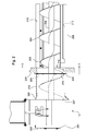
- the combine has a side wall 200, through which helical auger 202 of auger conveyor 52 extends.
- Helical auger 202 includes helical flights 204 that are fixed to an auger shaft 206.
- Shallow trough 68 is disposed inside the body 210 of combine 10, and has an inside surface 212 that is spaced a slight clearance distance away from the radially outermost extent of helical flights 204. This clearance distance is typically 1-3 cm.
- a triangular aperture 214 is formed in side wall 200 having a vertical extent that is slightly larger than the outer diameter of helical flights 204.
- Triangular aperture 214 has a lower surface 216 that is disposed at the same height as inside surface 212, and is preferably spaced a slight distance away from the radially outermost extent of helical flights 204 to provide room to adjust the position of helical flights 204 and to reduce grain damage. This distance is typically 1-3 cm.
- Lower surface 216 adjacent to shallow trough 68 at side wall 200 This arrangement provides a smooth transition between shallow trough 68 and the bottom surface of triangular aperture 214 that avoids a vertical wall which could resist the passage of grain from shallow trough 68 into and through triangular aperture 214 in side wall 200.
- a transition tube 218 has a central open passageway that extends from end to end and is configured to convey grain therethrough.
- Transition tube 218 has a first end and a second end. The first end defines a triangular aperture 223 at one end of the central open passageway of transition tube 218. This triangular aperture is fixed to the outside surface of side wall 200 by a flange 220 that extends radially outward from the triangular aperture of transition tube 218.
- Transition tube 218 extends between the outside surface of side wall 200 and the lower housing 222 of paddle elevator 53.
- Lower housing 222 encloses a pulley having a rotational axis that is coaxial with the rotational axis of auger shaft 206.
- Paddle-type grain elevators and the manner of their coupling to clean grain augers are well known in the art.
- transition tube 218 defines a circular aperture 227 at the other end of the central open passageway and seals against lower housing 222.
- Lower housing 222 has a circular opening of substantially the same diameter as the second end 226 of transition tube 218 to thereby permit the free flow of grain without any substantial barriers from second end 226 of transition tube 218 into the lower housing 222.
- FIGURE 3 is a right side view of the side wall 200 of agricultural combine 10 as taken at section line 3-3 in FIGURE 2 .
- a shallow trough 68 is in the form of two laterally extending planar sheets 300, 302 that are joined together by a laterally extending arcuate portion 304 located underneath rotational axis 306 of the auger. The center of arcuate portion 304 is also rotational axis 306.
- the triangular aperture 223 of transition tube 218 where it abuts side wall 200 is in the form of an isosceles triangle with a generally horizontal top side 308, two equal sides 310, 312, left and right upper vertices 314, 316, and a lower vertex 318 disposed between the two equal sides 310, 312 and pointing downward. All the vertices of the triangular aperture 223 of transition tube 218 are radiused, including the lower vertex 318.
- the center of the radius of lower vertex 318 is concentric with axis 306.
- the center of the radius of lower vertex 318, the inside surface of aperture 214, and the inside surface 212 are spaced the same distance from axis 306, and are all preferably spaced 1-3 cm from the outermost edge of auger flights 204.
- the two equal sides 310, 312 of the end of transition tube 218 that abuts side wall 200 are disposed immediately adjacent to and are at the same angle as planar portions 300, 302 of shallow trough 68 adjacent to arcuate portion 304.
- transition tube 218 By dimensioning and positioning the opening in transition tube 218 the same as the aperture 214 in side wall 200, and the same as the auger trough itself insures that no significant barriers are provided for grain flowing across the inner surface of auger trough 68, through aperture 214 in side wall 200, and into transition tube 218. This smooth transition enhances the flow of grain from the auger conveyor 52 into the paddle elevator 53.
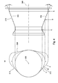
- transition tube 218 a top view of transition tube 218 is shown that helps illustrate and describe the smooth taper of the side walls of transition tube 218. This smooth transition enhances the flow of grain as it is pulled through transition tube 218 by auger flights 204
- transition tube 218 Three cross-sections A, B, C of transition tube 218 are shown superimposed on each other to the left of the top view of transition tube 218. These cross-sections show the contours of the inside surface of transition tube 218 in a direction perpendicular to the axis 306 of the helical flights 204.
- Cross section A is at the axial end of the transition tube 218 immediately adjacent to side wall 200 of combine 10. It shows the rounded triangular arrangement of the triangular aperture 223 of transition tube 218.
- Cross-section C is at the other axial end of the transition tube 218 immediately adjacent to lower housing 222. It shows the circular cross-section of transition tube 218.
- Cross-section B is intermediate these two sections, approximately in the middle of transition tube 218 and shows an intermediate width W that is the average of the overall width of transition tube 218 at each end.
- transition tube 218 Other cross-sections, although not specifically illustrated, are similarly proportioned to be proportionately as wide as their proportionate position all along the axial length of transition tube 218.
- the radially outermost inside surface portions 400, 402 of transition tube 218 appear to be straight lines with a constant axially-inward taper of angles alpha, beta, respectively over their entire length. This distributes the inward force of the auger flights 204 evenly against the grain they are conveying along the axial length of transition tube 218.
- angles alpha and beta are preferably the same, thereby causing the grain to exert equal and opposite forces on each side of the auger flights 204 as the auger rotates, thereby equalizing the lateral loads on the auger flights 204 and extending the life of the bearings that support the auger conveyor 52.
Landscapes
- Engineering & Computer Science (AREA)
- Mechanical Engineering (AREA)
- Life Sciences & Earth Sciences (AREA)
- Environmental Sciences (AREA)
- Threshing Machine Elements (AREA)
Applications Claiming Priority (1)
| Application Number | Priority Date | Filing Date | Title |
|---|---|---|---|
| US12/752,474 US8007353B1 (en) | 2010-04-01 | 2010-04-01 | Clean grain conveyor for an agricultural combine |
Publications (2)
| Publication Number | Publication Date |
|---|---|
| EP2371205A1 true EP2371205A1 (fr) | 2011-10-05 |
| EP2371205B1 EP2371205B1 (fr) | 2012-09-19 |
Family
ID=44144777
Family Applications (1)
| Application Number | Title | Priority Date | Filing Date |
|---|---|---|---|
| EP11158311A Active EP2371205B1 (fr) | 2010-04-01 | 2011-03-15 | Moissonneuse-batteuse agricole |
Country Status (3)
| Country | Link |
|---|---|
| US (1) | US8007353B1 (fr) |
| EP (1) | EP2371205B1 (fr) |
| BR (1) | BRPI1100915B1 (fr) |
Cited By (8)
| Publication number | Priority date | Publication date | Assignee | Title |
|---|---|---|---|---|
| US9044820B2 (en) | 2013-07-10 | 2015-06-02 | Kondex Corporation | Auger with laser cladding and/or laser heat treatment and method |
| US9686911B2 (en) | 2014-05-12 | 2017-06-27 | Kondex Corporation | Cutting blade with transverse hardened regions |
| US9717176B2 (en) | 2014-09-15 | 2017-08-01 | Kondex Corporation | Agricultural blades and machine parts with amorphous metal laser cladding |
| CN107846844A (zh) * | 2015-04-30 | 2018-03-27 | 凯斯纽荷兰(中国)管理有限公司 | 农业收割机的螺旋输送器组件 |
| US9992930B2 (en) | 2014-05-12 | 2018-06-12 | Kondex Corporation | Slicing disc mower knives |
| KR20190070275A (ko) * | 2017-12-12 | 2019-06-20 | 가부시끼 가이샤 구보다 | 콤바인 및 탈곡 장치 |
| US10462963B2 (en) | 2012-03-06 | 2019-11-05 | Kondex Corporation | Laser clad cutting edge for agricultural cutting components |
| CN113300522A (zh) * | 2021-05-11 | 2021-08-24 | 张涵宇 | 一种电机 |
Families Citing this family (10)
| Publication number | Priority date | Publication date | Assignee | Title |
|---|---|---|---|---|
| US9307699B2 (en) | 2013-02-28 | 2016-04-12 | Cnh Industrial America Llc | Transition chamber from auger to elevator in combine harvester |
| US9565803B2 (en) * | 2013-07-10 | 2017-02-14 | Kondex Corporation | Machine part with laser cladding and method |
| BE1022112B1 (nl) * | 2014-02-12 | 2016-02-16 | Cnh Industrial Belgium Nv | Oogstmachine |
| US20160057926A1 (en) * | 2014-08-29 | 2016-03-03 | Deere & Company | Integrated jackshaft for grain elevators of agricultural combines |
| US10257984B2 (en) * | 2014-11-14 | 2019-04-16 | Cnh Industrial America Llc | Agricultural harvester with paddles rotated about an axis of rotation that is parallel to a longitudinal axis of the harvester |
| US10648051B2 (en) | 2015-04-24 | 2020-05-12 | Kondex Corporation | Reciprocating cutting blade with cladding |
| US10201126B2 (en) * | 2015-04-30 | 2019-02-12 | Cnh Industrial America Llc | Combine harvester with elevator |
| US9736985B2 (en) * | 2015-04-30 | 2017-08-22 | Cnh Industrial America Llc | Agricultural harvester auger assembly |
| US9955629B2 (en) * | 2015-07-03 | 2018-05-01 | Cnh Industrial America Llc | Agricultural harvester with improved elevator geometry |
| US12685259B2 (en) * | 2023-11-14 | 2026-07-21 | Cnh Industrial America Llc | Grain tank sump for agricultural vehicle |
Citations (3)
| Publication number | Priority date | Publication date | Assignee | Title |
|---|---|---|---|---|
| US6053811A (en) | 1996-10-10 | 2000-04-25 | Case Corporation | Tailings monitor for an agricultural combine |
| US6350197B1 (en) | 2000-02-11 | 2002-02-26 | Case Corporation | Offset auger feed for a combine clean grain elevator |
| US20050186997A1 (en) * | 2004-02-23 | 2005-08-25 | Cnh America Llc | Combine tailings sensor system |
Family Cites Families (4)
| Publication number | Priority date | Publication date | Assignee | Title |
|---|---|---|---|---|
| US2410012A (en) * | 1945-07-12 | 1946-10-29 | John A Churchman | Portable grain elevator |
| US3265226A (en) * | 1964-09-24 | 1966-08-09 | Deere & Co | Grain tank and discharge means therefor |
| US3575306A (en) * | 1969-01-24 | 1971-04-20 | Helix Corp | Integrated single-pivot auger box |
| US5505583A (en) * | 1995-02-01 | 1996-04-09 | Courtesy Enterprises, Incorporated | Slope plates for particulate material truck box |
-
2010
- 2010-04-01 US US12/752,474 patent/US8007353B1/en active Active
-
2011
- 2011-03-15 EP EP11158311A patent/EP2371205B1/fr active Active
- 2011-03-31 BR BRPI1100915A patent/BRPI1100915B1/pt active IP Right Grant
Patent Citations (3)
| Publication number | Priority date | Publication date | Assignee | Title |
|---|---|---|---|---|
| US6053811A (en) | 1996-10-10 | 2000-04-25 | Case Corporation | Tailings monitor for an agricultural combine |
| US6350197B1 (en) | 2000-02-11 | 2002-02-26 | Case Corporation | Offset auger feed for a combine clean grain elevator |
| US20050186997A1 (en) * | 2004-02-23 | 2005-08-25 | Cnh America Llc | Combine tailings sensor system |
Cited By (10)
| Publication number | Priority date | Publication date | Assignee | Title |
|---|---|---|---|---|
| US10462963B2 (en) | 2012-03-06 | 2019-11-05 | Kondex Corporation | Laser clad cutting edge for agricultural cutting components |
| US9044820B2 (en) | 2013-07-10 | 2015-06-02 | Kondex Corporation | Auger with laser cladding and/or laser heat treatment and method |
| US9686911B2 (en) | 2014-05-12 | 2017-06-27 | Kondex Corporation | Cutting blade with transverse hardened regions |
| US9992930B2 (en) | 2014-05-12 | 2018-06-12 | Kondex Corporation | Slicing disc mower knives |
| US10206331B2 (en) | 2014-05-12 | 2019-02-19 | Kondex Corporation | Cutting blade with hardened regions |
| US9717176B2 (en) | 2014-09-15 | 2017-08-01 | Kondex Corporation | Agricultural blades and machine parts with amorphous metal laser cladding |
| CN107846844A (zh) * | 2015-04-30 | 2018-03-27 | 凯斯纽荷兰(中国)管理有限公司 | 农业收割机的螺旋输送器组件 |
| KR20190070275A (ko) * | 2017-12-12 | 2019-06-20 | 가부시끼 가이샤 구보다 | 콤바인 및 탈곡 장치 |
| CN113300522A (zh) * | 2021-05-11 | 2021-08-24 | 张涵宇 | 一种电机 |
| CN113300522B (zh) * | 2021-05-11 | 2022-07-12 | 江苏锡安达防爆股份有限公司 | 一种电机 |
Also Published As
| Publication number | Publication date |
|---|---|
| BRPI1100915B1 (pt) | 2018-12-18 |
| US8007353B1 (en) | 2011-08-30 |
| BRPI1100915A2 (pt) | 2012-08-14 |
| EP2371205B1 (fr) | 2012-09-19 |
Similar Documents
| Publication | Publication Date | Title |
|---|---|---|
| EP2371205B1 (fr) | Moissonneuse-batteuse agricole | |
| US6350197B1 (en) | Offset auger feed for a combine clean grain elevator | |
| US4907402A (en) | Unloading system | |
| US7717779B1 (en) | Combine with a conveyor switchable between swath deposit operation and chopper operation in different directions of rotation | |
| US8167691B2 (en) | Crop residue chopping and distributing arrangement for a combine harvester | |
| US8029347B2 (en) | Crop residue chopping-and-distributing arrangement for a combine | |
| US9033780B2 (en) | Biomass feed system using an air blanket for improved distribution within a collection device | |
| US4466447A (en) | Tailings return to threshing section or to cleaning section | |
| US8118651B2 (en) | Crop residue chopping and distributing arrangement for a combine | |
| US6884161B2 (en) | Rotary combine having a frusto-conical rotor housing | |
| US7427232B2 (en) | Clean grain and tailings conveying system for an agricultural combine | |
| US11259466B2 (en) | Agricultural elevator supplied by multiple cross augers | |
| US8864561B2 (en) | Harvested crop residue chopper and distribution arrangement for a combine with an impeller blower whose shape conforms to the contour of the straw chopper | |
| US8128466B2 (en) | Harvested material residue chopping and distributing arrangement for a combine | |
| US8147303B2 (en) | Harvested crop chopper remains and distribution arrangement for a combine | |
| EP3217782B1 (fr) | Moissonneuse agricole comprenant un élévateur tourné | |
| US6902477B2 (en) | Axial separator with guide vane | |
| EP3691439B1 (fr) | Capteur de volume pour système de renvoi de résidus de moissonneuse batteuse | |
| US20250151645A1 (en) | Grain tank sump for agricultural vehicle | |
| BR102024023800A2 (pt) | Tanque de grãos limpos e colheitadeira agrícola |
Legal Events
| Date | Code | Title | Description |
|---|---|---|---|
| PUAI | Public reference made under article 153(3) epc to a published international application that has entered the european phase |
Free format text: ORIGINAL CODE: 0009012 |
|
| AK | Designated contracting states |
Kind code of ref document: A1 Designated state(s): AL AT BE BG CH CY CZ DE DK EE ES FI FR GB GR HR HU IE IS IT LI LT LU LV MC MK MT NL NO PL PT RO RS SE SI SK SM TR |
|
| AX | Request for extension of the european patent |
Extension state: BA ME |
|
| GRAP | Despatch of communication of intention to grant a patent |
Free format text: ORIGINAL CODE: EPIDOSNIGR1 |
|
| 17P | Request for examination filed |
Effective date: 20120405 |
|
| RIC1 | Information provided on ipc code assigned before grant |
Ipc: A01F 12/46 20060101AFI20120419BHEP |
|
| RTI1 | Title (correction) |
Free format text: AGRICULTURAL COMBINE |
|
| GRAS | Grant fee paid |
Free format text: ORIGINAL CODE: EPIDOSNIGR3 |
|
| GRAA | (expected) grant |
Free format text: ORIGINAL CODE: 0009210 |
|
| AK | Designated contracting states |
Kind code of ref document: B1 Designated state(s): AL AT BE BG CH CY CZ DE DK EE ES FI FR GB GR HR HU IE IS IT LI LT LU LV MC MK MT NL NO PL PT RO RS SE SI SK SM TR |
|
| REG | Reference to a national code |
Ref country code: GB Ref legal event code: FG4D |
|
| REG | Reference to a national code |
Ref country code: CH Ref legal event code: EP |
|
| REG | Reference to a national code |
Ref country code: IE Ref legal event code: FG4D |
|
| REG | Reference to a national code |
Ref country code: AT Ref legal event code: REF Ref document number: 575542 Country of ref document: AT Kind code of ref document: T Effective date: 20121015 |
|
| REG | Reference to a national code |
Ref country code: DE Ref legal event code: R096 Ref document number: 602011000233 Country of ref document: DE Effective date: 20121115 |
|
| PG25 | Lapsed in a contracting state [announced via postgrant information from national office to epo] |
Ref country code: NO Free format text: LAPSE BECAUSE OF FAILURE TO SUBMIT A TRANSLATION OF THE DESCRIPTION OR TO PAY THE FEE WITHIN THE PRESCRIBED TIME-LIMIT Effective date: 20121219 Ref country code: HR Free format text: LAPSE BECAUSE OF FAILURE TO SUBMIT A TRANSLATION OF THE DESCRIPTION OR TO PAY THE FEE WITHIN THE PRESCRIBED TIME-LIMIT Effective date: 20120919 Ref country code: FI Free format text: LAPSE BECAUSE OF FAILURE TO SUBMIT A TRANSLATION OF THE DESCRIPTION OR TO PAY THE FEE WITHIN THE PRESCRIBED TIME-LIMIT Effective date: 20120919 Ref country code: LT Free format text: LAPSE BECAUSE OF FAILURE TO SUBMIT A TRANSLATION OF THE DESCRIPTION OR TO PAY THE FEE WITHIN THE PRESCRIBED TIME-LIMIT Effective date: 20120919 |
|
| REG | Reference to a national code |
Ref country code: NL Ref legal event code: VDEP Effective date: 20120919 |
|
| REG | Reference to a national code |
Ref country code: AT Ref legal event code: MK05 Ref document number: 575542 Country of ref document: AT Kind code of ref document: T Effective date: 20120919 |
|
| REG | Reference to a national code |
Ref country code: LT Ref legal event code: MG4D Effective date: 20120919 |
|
| PG25 | Lapsed in a contracting state [announced via postgrant information from national office to epo] |
Ref country code: LV Free format text: LAPSE BECAUSE OF FAILURE TO SUBMIT A TRANSLATION OF THE DESCRIPTION OR TO PAY THE FEE WITHIN THE PRESCRIBED TIME-LIMIT Effective date: 20120919 Ref country code: SI Free format text: LAPSE BECAUSE OF FAILURE TO SUBMIT A TRANSLATION OF THE DESCRIPTION OR TO PAY THE FEE WITHIN THE PRESCRIBED TIME-LIMIT Effective date: 20120919 Ref country code: SE Free format text: LAPSE BECAUSE OF FAILURE TO SUBMIT A TRANSLATION OF THE DESCRIPTION OR TO PAY THE FEE WITHIN THE PRESCRIBED TIME-LIMIT Effective date: 20120919 Ref country code: GR Free format text: LAPSE BECAUSE OF FAILURE TO SUBMIT A TRANSLATION OF THE DESCRIPTION OR TO PAY THE FEE WITHIN THE PRESCRIBED TIME-LIMIT Effective date: 20121220 |
|
| PG25 | Lapsed in a contracting state [announced via postgrant information from national office to epo] |
Ref country code: BE Free format text: LAPSE BECAUSE OF FAILURE TO SUBMIT A TRANSLATION OF THE DESCRIPTION OR TO PAY THE FEE WITHIN THE PRESCRIBED TIME-LIMIT Effective date: 20120919 Ref country code: CZ Free format text: LAPSE BECAUSE OF FAILURE TO SUBMIT A TRANSLATION OF THE DESCRIPTION OR TO PAY THE FEE WITHIN THE PRESCRIBED TIME-LIMIT Effective date: 20120919 Ref country code: EE Free format text: LAPSE BECAUSE OF FAILURE TO SUBMIT A TRANSLATION OF THE DESCRIPTION OR TO PAY THE FEE WITHIN THE PRESCRIBED TIME-LIMIT Effective date: 20120919 Ref country code: IS Free format text: LAPSE BECAUSE OF FAILURE TO SUBMIT A TRANSLATION OF THE DESCRIPTION OR TO PAY THE FEE WITHIN THE PRESCRIBED TIME-LIMIT Effective date: 20130119 Ref country code: NL Free format text: LAPSE BECAUSE OF FAILURE TO SUBMIT A TRANSLATION OF THE DESCRIPTION OR TO PAY THE FEE WITHIN THE PRESCRIBED TIME-LIMIT Effective date: 20120919 Ref country code: RO Free format text: LAPSE BECAUSE OF FAILURE TO SUBMIT A TRANSLATION OF THE DESCRIPTION OR TO PAY THE FEE WITHIN THE PRESCRIBED TIME-LIMIT Effective date: 20120919 |
|
| PG25 | Lapsed in a contracting state [announced via postgrant information from national office to epo] |
Ref country code: PT Free format text: LAPSE BECAUSE OF FAILURE TO SUBMIT A TRANSLATION OF THE DESCRIPTION OR TO PAY THE FEE WITHIN THE PRESCRIBED TIME-LIMIT Effective date: 20130121 Ref country code: SK Free format text: LAPSE BECAUSE OF FAILURE TO SUBMIT A TRANSLATION OF THE DESCRIPTION OR TO PAY THE FEE WITHIN THE PRESCRIBED TIME-LIMIT Effective date: 20120919 Ref country code: PL Free format text: LAPSE BECAUSE OF FAILURE TO SUBMIT A TRANSLATION OF THE DESCRIPTION OR TO PAY THE FEE WITHIN THE PRESCRIBED TIME-LIMIT Effective date: 20120919 |
|
| PG25 | Lapsed in a contracting state [announced via postgrant information from national office to epo] |
Ref country code: AT Free format text: LAPSE BECAUSE OF FAILURE TO SUBMIT A TRANSLATION OF THE DESCRIPTION OR TO PAY THE FEE WITHIN THE PRESCRIBED TIME-LIMIT Effective date: 20120919 |
|
| PLBE | No opposition filed within time limit |
Free format text: ORIGINAL CODE: 0009261 |
|
| STAA | Information on the status of an ep patent application or granted ep patent |
Free format text: STATUS: NO OPPOSITION FILED WITHIN TIME LIMIT |
|
| PG25 | Lapsed in a contracting state [announced via postgrant information from national office to epo] |
Ref country code: DK Free format text: LAPSE BECAUSE OF FAILURE TO SUBMIT A TRANSLATION OF THE DESCRIPTION OR TO PAY THE FEE WITHIN THE PRESCRIBED TIME-LIMIT Effective date: 20120919 Ref country code: RS Free format text: LAPSE BECAUSE OF FAILURE TO SUBMIT A TRANSLATION OF THE DESCRIPTION OR TO PAY THE FEE WITHIN THE PRESCRIBED TIME-LIMIT Effective date: 20120919 Ref country code: BG Free format text: LAPSE BECAUSE OF FAILURE TO SUBMIT A TRANSLATION OF THE DESCRIPTION OR TO PAY THE FEE WITHIN THE PRESCRIBED TIME-LIMIT Effective date: 20121219 |
|
| 26N | No opposition filed |
Effective date: 20130620 |
|
| REG | Reference to a national code |
Ref country code: DE Ref legal event code: R097 Ref document number: 602011000233 Country of ref document: DE Effective date: 20130620 |
|
| PG25 | Lapsed in a contracting state [announced via postgrant information from national office to epo] |
Ref country code: ES Free format text: LAPSE BECAUSE OF FAILURE TO SUBMIT A TRANSLATION OF THE DESCRIPTION OR TO PAY THE FEE WITHIN THE PRESCRIBED TIME-LIMIT Effective date: 20121230 Ref country code: MC Free format text: LAPSE BECAUSE OF NON-PAYMENT OF DUE FEES Effective date: 20130331 |
|
| PG25 | Lapsed in a contracting state [announced via postgrant information from national office to epo] |
Ref country code: CY Free format text: LAPSE BECAUSE OF FAILURE TO SUBMIT A TRANSLATION OF THE DESCRIPTION OR TO PAY THE FEE WITHIN THE PRESCRIBED TIME-LIMIT Effective date: 20120919 |
|
| REG | Reference to a national code |
Ref country code: FR Ref legal event code: ST Effective date: 20131129 |
|
| REG | Reference to a national code |
Ref country code: IE Ref legal event code: MM4A |
|
| PG25 | Lapsed in a contracting state [announced via postgrant information from national office to epo] |
Ref country code: AL Free format text: LAPSE BECAUSE OF FAILURE TO SUBMIT A TRANSLATION OF THE DESCRIPTION OR TO PAY THE FEE WITHIN THE PRESCRIBED TIME-LIMIT Effective date: 20120919 Ref country code: FR Free format text: LAPSE BECAUSE OF NON-PAYMENT OF DUE FEES Effective date: 20130402 Ref country code: IE Free format text: LAPSE BECAUSE OF NON-PAYMENT OF DUE FEES Effective date: 20130315 |
|
| PGFP | Annual fee paid to national office [announced via postgrant information from national office to epo] |
Ref country code: IT Payment date: 20140331 Year of fee payment: 4 |
|
| PG25 | Lapsed in a contracting state [announced via postgrant information from national office to epo] |
Ref country code: MT Free format text: LAPSE BECAUSE OF FAILURE TO SUBMIT A TRANSLATION OF THE DESCRIPTION OR TO PAY THE FEE WITHIN THE PRESCRIBED TIME-LIMIT Effective date: 20120919 |
|
| REG | Reference to a national code |
Ref country code: CH Ref legal event code: PL |
|
| PG25 | Lapsed in a contracting state [announced via postgrant information from national office to epo] |
Ref country code: LI Free format text: LAPSE BECAUSE OF NON-PAYMENT OF DUE FEES Effective date: 20140331 Ref country code: CH Free format text: LAPSE BECAUSE OF NON-PAYMENT OF DUE FEES Effective date: 20140331 |
|
| PG25 | Lapsed in a contracting state [announced via postgrant information from national office to epo] |
Ref country code: SM Free format text: LAPSE BECAUSE OF FAILURE TO SUBMIT A TRANSLATION OF THE DESCRIPTION OR TO PAY THE FEE WITHIN THE PRESCRIBED TIME-LIMIT Effective date: 20120919 |
|
| PG25 | Lapsed in a contracting state [announced via postgrant information from national office to epo] |
Ref country code: TR Free format text: LAPSE BECAUSE OF FAILURE TO SUBMIT A TRANSLATION OF THE DESCRIPTION OR TO PAY THE FEE WITHIN THE PRESCRIBED TIME-LIMIT Effective date: 20120919 |
|
| PG25 | Lapsed in a contracting state [announced via postgrant information from national office to epo] |
Ref country code: LU Free format text: LAPSE BECAUSE OF NON-PAYMENT OF DUE FEES Effective date: 20130315 Ref country code: MK Free format text: LAPSE BECAUSE OF FAILURE TO SUBMIT A TRANSLATION OF THE DESCRIPTION OR TO PAY THE FEE WITHIN THE PRESCRIBED TIME-LIMIT Effective date: 20120919 Ref country code: HU Free format text: LAPSE BECAUSE OF FAILURE TO SUBMIT A TRANSLATION OF THE DESCRIPTION OR TO PAY THE FEE WITHIN THE PRESCRIBED TIME-LIMIT; INVALID AB INITIO Effective date: 20110315 |
|
| GBPC | Gb: european patent ceased through non-payment of renewal fee |
Effective date: 20150315 |
|
| PG25 | Lapsed in a contracting state [announced via postgrant information from national office to epo] |
Ref country code: IT Free format text: LAPSE BECAUSE OF NON-PAYMENT OF DUE FEES Effective date: 20150315 |
|
| PG25 | Lapsed in a contracting state [announced via postgrant information from national office to epo] |
Ref country code: GB Free format text: LAPSE BECAUSE OF NON-PAYMENT OF DUE FEES Effective date: 20150315 |
|
| PGFP | Annual fee paid to national office [announced via postgrant information from national office to epo] |
Ref country code: DE Payment date: 20260219 Year of fee payment: 16 |