EP2371208A2 - Bodenträger für Stallboden und Stallboden mit derartigem Bodenträger - Google Patents
Bodenträger für Stallboden und Stallboden mit derartigem Bodenträger Download PDFInfo
- Publication number
- EP2371208A2 EP2371208A2 EP11156517A EP11156517A EP2371208A2 EP 2371208 A2 EP2371208 A2 EP 2371208A2 EP 11156517 A EP11156517 A EP 11156517A EP 11156517 A EP11156517 A EP 11156517A EP 2371208 A2 EP2371208 A2 EP 2371208A2
- Authority
- EP
- European Patent Office
- Prior art keywords
- floor beam
- floor
- bearing joist
- side walls
- profile part
- Prior art date
- Legal status (The legal status is an assumption and is not a legal conclusion. Google has not performed a legal analysis and makes no representation as to the accuracy of the status listed.)
- Withdrawn
Links
Images

Classifications
-
- A—HUMAN NECESSITIES
- A01—AGRICULTURE; FORESTRY; ANIMAL HUSBANDRY; HUNTING; TRAPPING; FISHING
- A01K—ANIMAL HUSBANDRY; AVICULTURE; APICULTURE; PISCICULTURE; FISHING; REARING OR BREEDING ANIMALS, NOT OTHERWISE PROVIDED FOR; NEW BREEDS OF ANIMALS
- A01K1/00—Housing animals; Equipment therefor
- A01K1/015—Floor coverings, e.g. bedding-down sheets ; Stable floors
- A01K1/0151—Grids; Gratings; Slatted floors
Definitions
- the invention relates to a floor beam for a floor of an animal shed, in particular a calf stable, a stable floor comprising such floor beams, and supporting beams therefor, as well as the supporting beams for this stable floor.
- Dutch patent application NL 7210627 discloses floor beams provided with a rubber extruded profile with a concrete supporting beam cast onto it.
- the extruded profile parts are provided with a cavity which extends in the longitudinal direction.
- the extruded profile parts are furthermore provided with corner parts extending opposite one another in the longitudinal direction, in the description referred to as extending parts, which are embedded in the concrete.
- a drawback of the floor beams shown in the Dutch patent application is that when they are subjected to a load, the extending parts mentioned above become detached from the concrete beam and thus wear down, and furthermore dirt and vermin can spread between the resulting spaces and gaps.
- the profile parts do not extend to the end of the beams so that the corners can still be damaged.
- the beams are not possible due to the cavities running in the longitudinal direction in which dirt may otherwise accumulate. Furthermore, the beams are apparently loosely placed on a manure channel element.
- the illustrated floor beams have been found to not be sufficiently durable in practice. In addition, the floor beams are heavy and cannot be replaced easily, and the installation is not secure. There is room for improvement with regard to the floor beams and the floor produced therewith.
- European patent application 1,336,336 discloses a stable floor consisting of concrete beams which are provided with a part clamped thereto which in turn is provided with a rubber walking surface. Such a structure is expensive and can easily become damaged.
- European patent application EP 2,138,289 describes a stable floor part provided with interconnected beams, which beams are provided with rubber profile parts on their walking surface. These profile parts are introduced into vibrated concrete by vibration in order to achieve good bonding.
- three beams which are formed at a distance from one another are interconnected by means of a connecting part which is integrally cast with the beams. This results in a relatively large surface which is not covered by rubber material. In addition, these relatively large and heavy parts are difficult to replace.
- the invention relates to a floor beam for a floor of an animal shed, in particular a calf stable, having side walls, a walking surface and a bottom surface
- the floor beam comprises a wooden bearing joist with a top layer of rubber material in order to provide a standing surface for livestock
- the top layer is a profile part which is clamped onto the wooden bearing joist and which is provided with parts extending into the wood, and which comprises mutually opposite corner parts which extend in the longitudinal direction of the profile part and partly along the side walls and which are partly embedded in the wood of the bearing joist and which form part of the side walls.
- the improved floor beam which is simple to produce increases the comfort of the livestock.
- the surface of the bearing joists is protected against wear.
- the wooden bearing joist comprises a dovetail profile milled in the longitudinal direction on the side of the profile part.
- the profile part is clamped onto the wooden bearing joist, in particular it surrounds the milled dovetail profile of the wooden bearing joist in a clamping manner.
- the distance between the corner parts 12 on the inner side 23 is slightly smaller than the local width of the wooden bearing joist.
- the profile part has a convex surface, in an embodiment having a radius of curvature of approximately 15-40 cm.
- a bottom contact surface is provided on either side of the floor beam, between the corner parts and the bearing joist, transversely to the side walls, which bottom contact surface slopes to the side walls in the position of use of the floor beam.
- the two bottom contact surfaces on either side of the floor beam are at a mutual angle of less than 180 degrees, in an embodiment less than 170 degrees.
- a bottom contact surface is present on either side of the floor beam, between the corner parts and the bearing joist, transversely to the side walls, which bottom contact surface slopes to the side walls in the position of use of the floor beam, wherein each of the corner parts of the profile part has a bottom contact surface and the wooden bearing joist has contact surfaces contacting the latter, wherein the bottom contact surfaces of the profile part have a larger downward incline than the contact surfaces of the wooden bearing joist.
- the invention furthermore relates to a stable floor comprising floor beams as described in this description, resting at a mutual distance from one another and mutually substantially parallel on supporting beams extending transversely across a manure cellar.
- the ends of the floor beams rest on the supporting beams, and wherein the supporting beams are provided with a tapering upper edge which is provided with tapering indentations in which the floor beams are held.
- the invention furthermore provides a floor beam for a floor of an animal shed, in particular a calf stable, having side walls, a walking surface and a bottom surface
- the floor beam comprises a bearing joist of concrete with a top layer of rubber material in order to provide a standing surface for livestock
- the top layer is a profile part onto which the bearing joist is formed and which is provided with parts which extend in the concrete, and which comprises mutually opposite corner parts which extend in the longitudinal direction of the profile part and partly along the side walls and which are partly embedded in the concrete of the bearing joist and which form part of the side walls.
- the livestock are more comfortable and the bearing joist is protected against damage.
- the floor beams in a stable floor can easily be replaced without requiring expensive hoisting equipment in the stable.
- As a result of the shape of the profile part a good bond to the bearing joist is achieved.
- the corner part prevents contact between manure and urine and the side of the bearing joist.
- each of the mutually opposite corner parts has a bottom contact surface with the bearing joist transversely to the side wall, wherein the bottom contact surfaces make a downward angle with respect to the walking surface, in an embodiment, a downward angle of approximately 5-15 degrees.
- a bottom contact surface is present on either side of the floor beam, between the corner parts and the bearing joist, transversely to the side walls, which bottom contact surface slopes to the side walls in the position of use of the floor beam.
- the two bottom contact surfaces on either side of the floor beam make a mutual angle of less than 180 degrees, in an embodiment of less than 170 degrees. Due to the fact that the seams descend, any dirt or moisture which has landed in the seams runs out of the seams again.
- the side walls of the bearing joist taper, in an embodiment at an angle of 25-35 degrees.
- the side walls of the corner parts taper with respect to one another.
- the side walls of the bearing joist taper and continue in one plane with the side walls of the bearing joist. As a result thereof, less manure and urine runs along the side walls of the bearing joist.
- the profile part has a convex surface, in an embodiment having a radius of curvature of approximately 30-50 cm.
- the transitions from the side of the corner parts which are turned towards the concrete are provided with curvatures.
- the curvatures prevent parts crumbling from the concrete bearing joist.
- the protruding bonding parts extend from the corner parts into the concrete beam, in an embodiment, the bonding parts extend in the longitudinal direction of the profile part, in a further embodiment, the bonding parts have a dovetail cross section.
- the bonding parts extend in an obliquely inward direction. As a result thereof, the corner parts no longer come away from the concrete. In addition, the edges of the concrete no longer crumble when subjected to point loads from hoofs.
- the bearing joist is made of self-sealing concrete.
- self-sealing concrete it is possible to achieve a smooth finish which can withstand the environment to which it is exposed.
- a good connection to and bond with the profile part is achieved.
- the bearing joist comprises a reinforcing element which extends in the longitudinal direction of the bearing joist.
- a reinforcing element may be a reinforcing iron bar.
- the profile part is substantially solid. This appears to offer sufficient comfort. A plane which is too resilient may cause spraining. Cavities may become receptacles for dirt. In addition, it is possible that the profile part becomes detached from the bearing joist if the profile part is pushed in too much.
- the profile part is made of rubber or silicone rubber or elastomer.
- a relatively hard kind of these materials is chosen. It has been found, in practice, that rubber is most resistant when subjected to the heavy load from the hoofs of the livestock and the aggressive urine.
- the profile part is an extruded profile part.
- the profile part may be produced by means of injection-moulding.
- the profile part is solid.
- the invention furthermore relates to supporting beams, obviously intended and suitable as supporting beams for the above-described stable floor, comprising a beam of self-sealing concrete and provided with a tapering upper edge which is provided with inwardly tapering indentations.
- the supporting beams offer minimal resistance to the urine and manure running into the manure cellar.
- the invention furthermore relates to a device provided with one or more of the characterizing measures described in the attached description and/or illustrated in the attached drawings.
- the attached figures show an embodiment of a floor beam and a stable floor provided with such a floor beam, in which:
- Fig. 1 shows a stable floor 1 in which a supporting beam 2 extends transversely across a manure cellar.
- This supporting beam 2 is provided with receiving parts 3 which in this case taper.
- the supporting beam 2 is partly provided with floor beams 4.
- the floor beams 4 have a bearing joist 5 and are provided with a rubber top layer.
- the rubber top layer is provided by means of a profile part 6.
- a strip 7, in this case a stainless steel strip may be provided across the ends thereof and be attached to the supporting beam 2.
- the supporting beam 2 may, for example, be cast from self-sealing concrete, as will be explained below.
- the self-sealing concrete may be provided with cast-in screwed sleeves into which bolts can be screwed so that the strips 7 can be secured and fixed to the supporting beam 2.
- the supporting beam 2 furthermore tapers in its longitudinal direction on the top side, as is illustrated in Fig. 1 .
- the floor beams 4 will have a width of approximately 6 to 10 cm for wooden beams and a width of approximately 8 to 15 cm for concrete bearing joists.
- the stable floor 1 is only provided with supporting beams 2 which extend transversely across the manure channel or manure cellar and floor beams 4 which extend in the longitudinal direction of the manure cellar or manure channel, the intermediate spaces between the bearing joists 4 also extend in the longitudinal direction of the manure channel.
- the intermediate spaces generally extend transversely to the livestock and not, as was customary until now, in the longitudinal direction of the livestock.
- the floor beams are only supported by the supporting beam 2 at their ends, the opening for draining manure and urine is as large as possible.
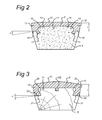
- Fig. 2 shows a cross section through a floor beam 4 for a floor of an animal shed, in particular a calf stable.
- the illustrated floor beam 4 from Fig. 2 has a concrete bearing joist 5 which is provided with reinforcement parts extending in the longitudinal direction.
- this bearing joist 5 is provided with a profile part 6.
- Profile part 6 has an upper surface 10 which provides a walking surface or standing surface for the livestock.
- the profile part 6 furthermore has a bottom surface 11 which is in contact with the concrete bearing joist 5.
- Profile part 6 furthermore has mutually opposite corner parts 12 which extend in the longitudinal direction. The corner parts 12 extend downwards and thus form part of the side walls of the floor beam.
- the side walls of the floor beam taper and the corner parts 12 are provided with lateral surfaces which extend in line with these tapering walls.
- the corner parts 12 are partly embedded in the concrete of the bearing joist 5.
- the corner parts 12 are furthermore provided with bonding parts 13 and 13'. These bonding parts have a dovetail cross section.
- these bonding parts 13, 13' are formed on the parts of the corner parts 12 of profile part 6 which are situated or embedded in the concrete.
- these bonding parts 13, 13' are directed inwardly and face the beam.
- the bonding parts extend obliquely in an inward direction. In particular, they extend along lines which intersect in the beam.
- the profile parts will not become detached from the concrete bearing joist when the livestock exerts pressure on the upper side thereof, as a result of which the rubber of profile part 6 is pushed in.
- the bottom side 11 of profile part 6 is furthermore provided with protruding parts 14, 14' which extend in the concrete of bearing joist 5. This prevents further detachment of the corner parts 12 of the concrete bearing joist.
- the corner parts 12 of profile part 6 furthermore have a bottom surface 16 which bears against and absorbs pressure from contact surface 17 of the concrete beam.
- the contact surface makes an angle ⁇ , as indicated in Fig. 2 , with a line which connects the corner parts to one another. Due to this angle ⁇ which, in practice, will be approximately 5 to 15°, any moisture which may seep between the boundary surface is readily pressed out again when livestock exerts pressure on the standing surface 10.
- the contact surface has a seam. These seams run downwards towards the side walls. If any dirt or moisture should end up therein, it will be removed and/or pushed out the latter again as a result of the sloping direction.
- the standing surface 10 of profile part 6 has a curved or convex surface 10, viewed in cross section.
- manure and urine readily runs off the profile part 6.
- the floor beam from Fig. 2 is produced by placing a profile part 6 in a mould and then pouring self-sealing concrete into the mould. If desired, a mould can also be filled with self-sealing concrete and profile part 6 is laid on top thereof. However, it is preferred to pour the concrete on the profile part, as a result of which any air inclusions between the concrete and profile part 6 are prevented.
- Fig. 3 shows an alternative embodiment of a floor beam 4.
- the bearing joist 5' is not made of concrete, but of wood. Compared to concrete, such a floor beam 4 has the advantage that it is lighter and easier to handle.
- a profile part 6 is clamped onto the wood of the bearing joist 5'.
- the upper side of the bearing joist 5' is made in the shape of a dovetail.
- the profile part 6 is furthermore provided, on the lower side 11 which bears against and/or rests on the wooden bearing joist 5, with a part 22 extending into the wood. When a load is exerted on the standing surface 10, this part will help to prevent the corner parts 12 from becoming detached from the wooden bearing joist 5'. It will be clear that the distance between the corner parts 12 will be chosen to be slightly smaller than the distance between the milled indentations on the wooden bearing joist, as a result of which corner part 6 clamps onto the wooden bearing joist.
- the contact surface 20 which is the contact surface of profile part 6, and contact surface 22, which is the contact surface of the wooden bearing joist, due to the pressure on the standing surface 10.
- the contact surface 20 is arranged at an angle ⁇ with respect to a connecting line L and is thus directed downwards.
- the contact surface 21 of the bearing joist is also arranged at an angle with respect to this connecting line, as a result of which moisture will drain away in a downward direction.
- the angle ⁇ of profile part 6 will be greater than the angle which the contact surface 21 makes with respect to the line 1.
- profile part 6 will cause a pressure effect on the beam.
- livestock exerts pressure on the standing surface 10
- moisture and possibly dirt will be pushed out of this contact seam.
- the wooden bearing joist also has tapering side walls, which tapering continues with the side walls of corner parts 12.
- manure readily runs off the standing surface and will contact the side walls as little as possible.
- the wooden floor beam will be narrower than the concrete floor beam.
- the wooden floor beam will generally be approximately 7-15 cm wide.
- the concrete floor beam will generally be approximately 8-15 cm wide.
- the corner parts 12, having a height 1 run slightly straighter than the tapering side walls of the bearing joists 5 and 5'.
- these side walls of corner parts 12 continue in the same direction and taper as the side walls of the bearing joists 5, 5'.
- profile part 6 will be made of rubber. Rubber has the advantage that it feels comfortable to animals and is inexpensive to produce.
- the profile parts may be made from a rubber-like plastic, for example an elastomer or a silicone rubber, although a less flexible type thereof will have to be chosen in order to ensure a sufficient degree of durability.
- the self-sealing concrete of the bearing joist 5 from Fig. 2 often comprises cement, a filler, such as for example fly ash or limestone flour.
- a plasticizer is added.
- the plasticizer is a polycarboxylate, resulting in what is referred to as a third-generation self-sealing concrete.
- Such a concrete is particularly suitable in this floor beam 4 and the supporting beams 2 since the urine and manure have relatively little effect, due to the smooth and dense surface.
Landscapes
- Life Sciences & Earth Sciences (AREA)
- Environmental Sciences (AREA)
- Zoology (AREA)
- Animal Husbandry (AREA)
- Biodiversity & Conservation Biology (AREA)
- Floor Finish (AREA)
- Housing For Livestock And Birds (AREA)
- Building Environments (AREA)
Applications Claiming Priority (1)
| Application Number | Priority Date | Filing Date | Title |
|---|---|---|---|
| NL2004490A NL2004490C2 (nl) | 2010-03-31 | 2010-03-31 | Vloerbalk voor een stalvloer en een stalvloer voorzien van een dergelijke vloerbalk. |
Publications (2)
| Publication Number | Publication Date |
|---|---|
| EP2371208A2 true EP2371208A2 (de) | 2011-10-05 |
| EP2371208A3 EP2371208A3 (de) | 2011-11-02 |
Family
ID=42829823
Family Applications (1)
| Application Number | Title | Priority Date | Filing Date |
|---|---|---|---|
| EP11156517A Withdrawn EP2371208A3 (de) | 2010-03-31 | 2011-03-02 | Bodenträger für Stallboden und Stallboden mit derartigem Bodenträger |
Country Status (3)
| Country | Link |
|---|---|
| EP (1) | EP2371208A3 (de) |
| DE (1) | DE202011003510U1 (de) |
| NL (1) | NL2004490C2 (de) |
Families Citing this family (8)
| Publication number | Priority date | Publication date | Assignee | Title |
|---|---|---|---|---|
| NL2006339C2 (nl) * | 2011-03-04 | 2012-09-05 | G Van Beek & Zn Kalverstalinrichting B V | Mestkelder voor een stal. |
| NL2013022B1 (en) | 2014-06-18 | 2016-07-05 | G Van Beek & Zn Kalverstalinrichting B V | Manure scraper. |
| BE1023628B1 (nl) * | 2015-11-18 | 2017-05-19 | Gebroeders Van Hessche bvba | Vloerelement |
| DE102016105543A1 (de) * | 2016-03-24 | 2017-09-28 | Hartmann Grundbesitz Gmbh & Co. Kg | Ablagekissen |
| EP3707997A1 (de) | 2019-03-15 | 2020-09-16 | G. van Beek & Zn. Kalverstalinrichting B.V. | Stall mit einem belüftungssystem und einem abfallentsorgungssystem |
| EP3707996A1 (de) | 2019-03-15 | 2020-09-16 | G. van Beek & Zn. Kalverstalinrichting B.V. | Stall mit einem belüftungssystem und einem abfallentsorgungssystem |
| EP3937619A1 (de) | 2019-03-15 | 2022-01-19 | G. van Beek & Zn. Kalverstalinrichting B.V. | Stall mit einem belüftungssystem und einem abfallentsorgungssystem |
| EP4173478B1 (de) | 2021-07-12 | 2025-02-26 | Insolute B.V. | Stall mit einem abfallentfernungssystem |
Citations (3)
| Publication number | Priority date | Publication date | Assignee | Title |
|---|---|---|---|---|
| NL7210627A (de) | 1971-08-24 | 1973-02-27 | ||
| EP1336336A1 (de) | 2002-02-06 | 2003-08-20 | Gunnar Fritz | Anordnung für Spaltenboden in einem Stall |
| EP2138289A1 (de) | 2008-06-23 | 2009-12-30 | Rudolf Schwarz | Verfahren und Vorrichtung zur Herstellung eines Längsspaltenrostelements |
Family Cites Families (2)
| Publication number | Priority date | Publication date | Assignee | Title |
|---|---|---|---|---|
| AT341819B (de) * | 1976-01-08 | 1977-06-15 | Wolf Johann Gmbh Kg | Spaltenboden |
| US5113794A (en) * | 1991-09-03 | 1992-05-19 | Larry Rahm | Animal shelter flooring apparatus |
-
2010
- 2010-03-31 NL NL2004490A patent/NL2004490C2/nl not_active IP Right Cessation
-
2011
- 2011-03-02 EP EP11156517A patent/EP2371208A3/de not_active Withdrawn
- 2011-03-04 DE DE202011003510U patent/DE202011003510U1/de not_active Expired - Lifetime
Patent Citations (3)
| Publication number | Priority date | Publication date | Assignee | Title |
|---|---|---|---|---|
| NL7210627A (de) | 1971-08-24 | 1973-02-27 | ||
| EP1336336A1 (de) | 2002-02-06 | 2003-08-20 | Gunnar Fritz | Anordnung für Spaltenboden in einem Stall |
| EP2138289A1 (de) | 2008-06-23 | 2009-12-30 | Rudolf Schwarz | Verfahren und Vorrichtung zur Herstellung eines Längsspaltenrostelements |
Also Published As
| Publication number | Publication date |
|---|---|
| EP2371208A3 (de) | 2011-11-02 |
| DE202011003510U1 (de) | 2011-05-05 |
| NL2004490C2 (nl) | 2011-10-04 |
Similar Documents
| Publication | Publication Date | Title |
|---|---|---|
| EP2371208A2 (de) | Bodenträger für Stallboden und Stallboden mit derartigem Bodenträger | |
| EP2371209A2 (de) | Bodenträger für Stallboden und Stallboden mit derartigem Bodenträger | |
| US10238084B2 (en) | Cattle floor | |
| US5000621A (en) | Apparatus for forming a trench | |
| US7784419B2 (en) | Floating dock structure | |
| US20190380298A1 (en) | Floor construction element | |
| US2227581A (en) | Anchoring molding strip for floor mats and combination of elements in use thereof | |
| US8347574B2 (en) | Joint elements for slabs | |
| US3824960A (en) | Floor structure | |
| US20050029751A1 (en) | Sealing device for sealing joints, and hollow-profile strip therefor | |
| GB2276641A (en) | Skirting, e.g. for use as a stable bank | |
| KR102335429B1 (ko) | 평철을 사용한 콘슬라트 | |
| KR100758560B1 (ko) | 구배 프리캐스트 트렌치 구조 | |
| EP2243355A1 (de) | Modularer belüfteter Fußbodenbelag, insbesondere für Ställe und/oder Schweinefarmen | |
| US6923145B2 (en) | Flume flush floor for livestock | |
| KR20220117510A (ko) | I-bar를 사용한 돈사용 바닥구조물 | |
| US4227486A (en) | Farrowing pen | |
| US9528240B2 (en) | Safety edge sports channel | |
| KR101208411B1 (ko) | 콘크리트 바닥 시공용 조인트 장치 | |
| KR102534211B1 (ko) | 아이(i)자형으로 철근을 보강한 콘슬라트 받침대 | |
| JP7141145B1 (ja) | 水路側壁用嵩上壁 | |
| Graves | Free stall design and construction criteria | |
| US20220354084A1 (en) | A Flooring System Support Unit In A Modular Flooring System for Construction of a Piggery with A Plurality of Pigsties With Underlying Manure Channels | |
| JP5268760B2 (ja) | 床化粧材 | |
| EP1855519A1 (de) | Fussbodenmatte zur verwendung durch tiere |
Legal Events
| Date | Code | Title | Description |
|---|---|---|---|
| PUAI | Public reference made under article 153(3) epc to a published international application that has entered the european phase |
Free format text: ORIGINAL CODE: 0009012 |
|
| PUAL | Search report despatched |
Free format text: ORIGINAL CODE: 0009013 |
|
| AK | Designated contracting states |
Kind code of ref document: A2 Designated state(s): AL AT BE BG CH CY CZ DE DK EE ES FI FR GB GR HR HU IE IS IT LI LT LU LV MC MK MT NL NO PL PT RO RS SE SI SK SM TR |
|
| AX | Request for extension of the european patent |
Extension state: BA ME |
|
| AK | Designated contracting states |
Kind code of ref document: A3 Designated state(s): AL AT BE BG CH CY CZ DE DK EE ES FI FR GB GR HR HU IE IS IT LI LT LU LV MC MK MT NL NO PL PT RO RS SE SI SK SM TR |
|
| AX | Request for extension of the european patent |
Extension state: BA ME |
|
| RIC1 | Information provided on ipc code assigned before grant |
Ipc: A01K 1/015 20060101AFI20110927BHEP |
|
| STAA | Information on the status of an ep patent application or granted ep patent |
Free format text: STATUS: THE APPLICATION IS DEEMED TO BE WITHDRAWN |
|
| 18D | Application deemed to be withdrawn |
Effective date: 20120503 |