EP2371253A2 - Siège de toilettes - Google Patents
Siège de toilettes Download PDFInfo
- Publication number
- EP2371253A2 EP2371253A2 EP11159186A EP11159186A EP2371253A2 EP 2371253 A2 EP2371253 A2 EP 2371253A2 EP 11159186 A EP11159186 A EP 11159186A EP 11159186 A EP11159186 A EP 11159186A EP 2371253 A2 EP2371253 A2 EP 2371253A2
- Authority
- EP
- European Patent Office
- Prior art keywords
- toilet seat
- toilet
- joint
- securing element
- bolt
- Prior art date
- Legal status (The legal status is an assumption and is not a legal conclusion. Google has not performed a legal analysis and makes no representation as to the accuracy of the status listed.)
- Withdrawn
Links
Images





Classifications
-
- A—HUMAN NECESSITIES
- A47—FURNITURE; DOMESTIC ARTICLES OR APPLIANCES; COFFEE MILLS; SPICE MILLS; SUCTION CLEANERS IN GENERAL
- A47K—SANITARY EQUIPMENT; ACCESSORIES THEREFOR, e.g. TOILET ACCESSORIES
- A47K13/00—Seats or covers for all kinds of closets
- A47K13/24—Parts or details not covered in, or of interest apart from, groups A47K13/02 - A47K13/22
- A47K13/26—Mounting devices for seats or covers
-
- A—HUMAN NECESSITIES
- A47—FURNITURE; DOMESTIC ARTICLES OR APPLIANCES; COFFEE MILLS; SPICE MILLS; SUCTION CLEANERS IN GENERAL
- A47K—SANITARY EQUIPMENT; ACCESSORIES THEREFOR, e.g. TOILET ACCESSORIES
- A47K13/00—Seats or covers for all kinds of closets
- A47K13/12—Hinges
Definitions
- the invention relates to a toilet seat with a toilet lid, a toilet seat and at least one joint. Furthermore, the toilet seat comprises a bolt which can be connected firmly to the toilet bowl, via which the toilet lid and the toilet seat are attachable to the toilet bowl.
- the hinge comprises a recess in which the bolt is receivable, wherein the bolt has a circumferential groove in which a securing element of the toilet seat snaps into a mounting position, so that the toilet lid, the toilet seat and the joint formed Unit is firmly connected to the toilet bowl.
- the securing element Via a manually operable button, the securing element can be rotated about an axis of rotation, so that the securing element is released from the groove and the unit formed from the toilet lid, the toilet seat and the hinge is removable from the bolt and thus from the toilet bowl.
- a quick release is formed, with the help of the toilet seat is easily removable from the toilet bowl and easily attachable to this.
- the toilet seat on a soft close so that a fall of the lid is avoided.
- the joint of the toilet seat comprises a main body, a first arm rotatable about a longitudinal axis of the main body and a second arm likewise rotatable about this longitudinal axis.
- the first arm is connectable to the toilet lid via a first connection
- the second arm is connectable to the toilet seat via a second connection.
- the first connection and / or the second connection are preferably designed as detachable connections, so that the toilet lid or the toilet seat can be easily replaced non-destructively. In this way, in the event of damage to the toilet seat or toilet seat this can be easily replaced or it can, for example, a toilet seat cover to be replaced if the user of the toilet seat no longer like the motive and he has decided on a new one.
- the joint is in particular designed as a hinge, wherein the two arms of the hinge are preferably connected by screws to the toilet lid or the toilet seat.
- the securing element is arranged to be translationally movable and if the securing element is thereby translationally moved upon actuation of the button such that it engages in the groove of the bolt.
- the securing element in particular comprises a slot through which the bolt at least partially protrudes when the unit formed from the toilet lid, the toilet seat and the joint is placed on the bolt and thus on the toilet bowl.
- the securing element is preferably held in the fastening position via at least one spring. This ensures that the securing element is automatically moved by the spring into the fastening position when the unit formed from the toilet lid, the toilet seat and the joint is placed on the bolt, so that this unit is automatically attached to the bolt and such attachment can not be forgotten. When releasing the securing element from the attachment position for removing the unit formed from the toilet lid, the toilet seat and the joint this is translationally moved against the spring force of the spring.
- the toilet lid and the body are connected to each other via a soft close, so that the toilet lid automatically lowers slowly and thus falling down the toilet lid and any damage to the toilet lid and / or the toilet seat is avoided.
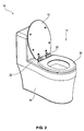
- FIG. 1 a perspective view of a toilet 10 is shown.
- the toilet 10 includes a toilet bowl 14 and a mounted on this Toilet seat 12.
- the toilet seat 12 in turn has a toilet lid 16, a toilet seat 18, two joints 20, 22 and two fasteners 24, 26, with the help of the toilet lid 16, the toilet seat 18 and the joints 20, 22 formed unit on the Toilet bowl 14 is mountable.
- FIG. 2 is a perspective view of the toilet 10 after FIG. 1 shown, wherein the toilet lid 16 of the toilet seat 12 is folded up.
- the joints 20, 22 are formed such that the toilet lid 16 connected via the joints 20, 22 with the toilet seat 18 and the toilet bowl 14 is rotatable relative to the toilet bowl 14 and the toilet seat 18 about the longitudinal axis of the joints 20, 22.
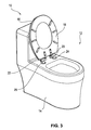
- FIG. 3 a perspective view of the toilet 10, wherein both the toilet lid 16 and the toilet seat 18 are folded up. Elements with the same structure or the same function have the same reference numerals.
- FIG. 4 is a perspective view of the toilet 10 after the FIGS. 1 to 3 shown, wherein one of the toilet lid 16, the toilet seat 18 and the joints 20, 22 formed unit 28 is removed from the fasteners 24, 26 and thus from the toilet bowl 14.
- the joints 20, 22 comprise a quick-release mechanism, which will be described in more detail in connection with the following figures, with the aid of which the unit 28 can be easily detached from and fastened to the fastening elements 24, 26.
- the fastening elements 24, 26 each comprise a bolt 30, 32, via which the unit 28 is fastened on the toilet bowl 14.
- FIG. 5 two perspective views of the unit 28 are shown, wherein the left-hand view shows a top view and the right-hand view shows a bottom view.
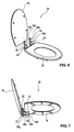
- FIG. 6 a perspective view of the unit 28 with the toilet lid 16 removed.
- the joints 20, 22 each comprise a first connecting element 34, 36, to which the toilet lid 16 can be fastened via a first connection.
- this first connection is a screw connection, wherein each of the first connection elements 34, 36 can be connected to the toilet lid 16 via two screws 38a to 38d.
- FIG. 7 is shown a perspective view of the unit 28, wherein the toilet seat 18 is removed from the joints 20, 22.
- the joints 20, 22 each include a second connecting element 40, 42, which is connectable via a second connection with the toilet seat 18.
- the second connection is also designed as a screw connection, so that the toilet seat 18 can be connected via two screws 30e to 38g to the second connecting elements 40, 42 and thus to the joints 20, 22.
- a modular design of the unit 28 is thus achieved from a toilet lid 16, a toilet seat 18 and two separate joints 20, 22.
- a simple replacement of one of these components 16, 18, 20, 22 is achieved if this is damaged, for example.
- toilet seat cover can in this way, for example, toilet seat cover to be replaced if you no longer like the theme of the old toilet lid and you want a new toilet lid.
- first connection and / or the second connection may also be formed not as a screw connection but, for example, as an adhesive, plug-in, latching and / or clamping connection.
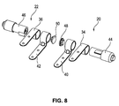
- FIG. 8 is a perspective view of the two joints 20, 22 shown.
- the two joints 20, 22 in addition to the connecting elements 34, 36, 40, 42 each have a base body 44, 46, in which the mechanics of the aforementioned quick release and the mechanics of a soft closing mechanism for the toilet lid 16 are integrated. Furthermore, the respective connecting elements 34, 36, 40, 42 are placed on the basic bodies 44, 46.
- each joint 20, 22 comprises a cover member 48, 50, through which the penetration of dirt into the integrated in the bodies 44, 46 mechanism is prevented.
- FIG. 9 is a perspective view of the joint 22 and the fastener 26 is shown, wherein the joint 22 is placed on the fastener 26 and connected thereto.
- the fastening element 26 comprises, in addition to the bolt 32 on which the joint 22 is mounted, a screw 52, by means of which the fastening element 52 can be fastened to the toilet bowl 14, not shown.
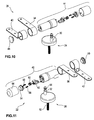
- FIG. 10 is shown a perspective view of the first joint 20 and the first fastening element 24, wherein the joint 20 and the fastening element 24 are not connected to each other.
- FIG. 11 is a perspective view of the second joint 22 and the second fastener 26 is shown.
- the first joint 20 and the second joint 22 as well as the first fastening element 24 and the second fastening element 26 are constructed analogously to one another, so that the structure of the second joint 22 and the second fastening element 26 will be described below to simplify the description.
- the statements apply correspondingly to the first joint 20 and the first fastening element 24.
- the main body 46 of the second joint 22 comprises a manually operable button 54, three springs 56 to 60, a securing element 62 and a sleeve 64 for protecting the mechanism arranged in the interior of the main body 46. Further, the main body 46 has an in FIG. 11 non-visible recess into which the bolt 32 at least partially protrudes when the hinge 22 is placed on the fastener 26, and thus the unit 28 is mounted on the toilet bowl 14.
- the bolt 32 of the fastener 26 includes a circumferential groove 66 into which the fuse element 62 engages when the fuse element 62 is disposed in a mounting position.
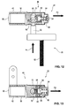
- FIG. 12 is a sectional view of the joint 22 and the fastener 26 when placing the hinge 22 on the fastener 26 is shown.
- the bolt 32 of the fastening element 26 is inserted into the recess of the joint 22.
- the bolt 32 has on the side facing away from the screw 52 a chamfered chamfer 68 through which the securing element 52 moves when moving towards each other of the joint 22 and the fastener 26 by the contact to this chamfer 68 in the direction of the arrow P2 against the spring force of the spring 60 is and thereby slides on the surface of the chamfer 68.
- FIG. 13 is a sectional view of the joint 22 and the fastener 26 in the in FIG. 12 shown state shown.
- the securing element 62 comprises an engagement element 70 which engages in the circumferential groove 66 of the fastener 26 and is engaged with the bolt 32 when the hinge 22 and the fastener 26 are disposed in an attachment position.
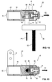
- This attachment position is in a sectional view in FIG. 14 and FIG. 15 shown.
- the joint 22 and the fastener 26 are moved toward each other so far that the bolt 32 almost completely fills the recess of the joint 22 and the engagement member 70 engages in the circumferential groove 66.
- the securing element 62 is for this purpose moved by the spring force of the spring 60 against the direction of the arrow P2, so that the engagement between the engaging member 70 and the bolt 32 is automatically established when the bolt 32 is moved far enough into the recess of the joint 22.
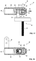
- FIG. 16 is a sectional view of the joint 22 and the fastener 26 is shown.
- the button 54 is manually operated, that is moved in the direction of arrow P3.
- the force required for this purpose is applied by the actuator of the knob 54.
- two fixedly connected to the knob 54 engaging elements 72, 74 are moved relative to the securing element 62 until they engage behind a survey 76 of the securing element 62 and thus the button 54 is engaged with the securing element 62.
- FIG. 17 is a sectional view of the joint 22 and the fastener 26 is shown, wherein in FIG. 17 the state is shown after the button 54 is released after the operation.
- the button 54 is moved by the spring force of the springs 56, 58 in the direction of the arrow P2.
- the securing element 62 is also moved in the direction of the arrow P2, so that the engagement element 70 of the securing element 62 no longer engages in the peripheral groove 66 of the bolt 32 of the fastening element 26. In this way, the securing element 62 is moved out of the fastening position and thus the connection between the bolt 32 and the joint 22 is released.
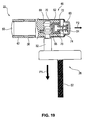
- FIG. 18 is a further sectional view of the joint 22 and the fastener 26 in the in FIG. 17 shown state shown.
Landscapes
- Health & Medical Sciences (AREA)
- Public Health (AREA)
- Toilet Supplies (AREA)
Applications Claiming Priority (1)
| Application Number | Priority Date | Filing Date | Title |
|---|---|---|---|
| DE201020000453 DE202010000453U1 (de) | 2010-03-24 | 2010-03-24 | Toilettensitz |
Publications (2)
| Publication Number | Publication Date |
|---|---|
| EP2371253A2 true EP2371253A2 (fr) | 2011-10-05 |
| EP2371253A3 EP2371253A3 (fr) | 2013-03-06 |
Family
ID=42234942
Family Applications (1)
| Application Number | Title | Priority Date | Filing Date |
|---|---|---|---|
| EP11159186A Withdrawn EP2371253A3 (fr) | 2010-03-24 | 2011-03-22 | Siège de toilettes |
Country Status (2)
| Country | Link |
|---|---|
| EP (1) | EP2371253A3 (fr) |
| DE (1) | DE202010000453U1 (fr) |
Cited By (5)
| Publication number | Priority date | Publication date | Assignee | Title |
|---|---|---|---|---|
| CN103202675A (zh) * | 2013-03-22 | 2013-07-17 | 厦门瑞尔特卫浴科技股份有限公司 | 快速拆装的支架结构 |
| DE102014109418A1 (de) * | 2014-05-02 | 2015-11-05 | Hamberger Industriewerke Gmbh | WC-Sitzgelenk und WC-Sitzgarnitur |
| WO2017008184A1 (fr) * | 2015-07-10 | 2017-01-19 | 乐特瑞(厦门)卫浴有限公司 | Fixation de couvercle de toilette |
| CN112914407A (zh) * | 2019-12-06 | 2021-06-08 | 吉博力国际股份公司 | 用于安装马桶支撑件的铰链 |
| IT202400000603A1 (it) * | 2024-01-15 | 2025-07-15 | Diesse S N C Di Barnocchi Decio | Cerniera per copri-water |
Families Citing this family (4)
| Publication number | Priority date | Publication date | Assignee | Title |
|---|---|---|---|---|
| WO2013022409A1 (fr) * | 2011-08-08 | 2013-02-14 | Eczacibaşi Yapi Gereçleri̇ Sanayi̇ Ve Ticaret Anonim Şi̇rketi̇ | Système de charnière pour monter le siège de toilettes sur la cuvette |
| DE202012105008U1 (de) * | 2012-12-21 | 2014-03-24 | Ortwein Gmbh | Montagefreundliche Verbindungssysteme für Sanitärprodukte |
| DE202018105278U1 (de) * | 2018-09-14 | 2019-12-17 | Evac Gmbh | Scharnierlagervorrichtung zur schwenkbaren Befestigung eines Deckels und/oder eines Sitzes an einem Becken einer Toilette |
| EP4063269A1 (fr) * | 2021-03-26 | 2022-09-28 | I.Gluesystems GmbH | Dispositif de fixation, en particulier dispositif de fixation du siège de toilettes |
Citations (1)
| Publication number | Priority date | Publication date | Assignee | Title |
|---|---|---|---|---|
| DE202009008303U1 (de) | 2009-06-16 | 2009-08-20 | Eisl Sanitär Ges.m.b.H. | Toilettensitz |
Family Cites Families (3)
| Publication number | Priority date | Publication date | Assignee | Title |
|---|---|---|---|---|
| IT1295337B1 (it) * | 1997-01-21 | 1999-05-12 | Sipex S N C Di Cavagna Livio & | Dispositivo di connessione rapida particolarmente per applicare un'asse di copertura a un water |
| US6070295A (en) * | 1998-09-22 | 2000-06-06 | Bemis Manufacturing Company | Quick release toilet seat hinge with swivel |
| ITMI20071193A1 (it) * | 2007-06-13 | 2008-12-14 | Cavagna & Sipex Internat S R L | Dispositivo frenante interponibile tra elementi reciprocamente ruotabili. |
-
2010
- 2010-03-24 DE DE201020000453 patent/DE202010000453U1/de not_active Expired - Lifetime
-
2011
- 2011-03-22 EP EP11159186A patent/EP2371253A3/fr not_active Withdrawn
Patent Citations (1)
| Publication number | Priority date | Publication date | Assignee | Title |
|---|---|---|---|---|
| DE202009008303U1 (de) | 2009-06-16 | 2009-08-20 | Eisl Sanitär Ges.m.b.H. | Toilettensitz |
Cited By (8)
| Publication number | Priority date | Publication date | Assignee | Title |
|---|---|---|---|---|
| CN103202675A (zh) * | 2013-03-22 | 2013-07-17 | 厦门瑞尔特卫浴科技股份有限公司 | 快速拆装的支架结构 |
| CN103202675B (zh) * | 2013-03-22 | 2015-03-11 | 厦门瑞尔特卫浴科技股份有限公司 | 快速拆装的支架结构 |
| DE102014109418A1 (de) * | 2014-05-02 | 2015-11-05 | Hamberger Industriewerke Gmbh | WC-Sitzgelenk und WC-Sitzgarnitur |
| DE102014109418B4 (de) | 2014-05-02 | 2023-04-20 | Hamberger Industriewerke Gmbh | WC-Sitzgelenk und WC-Sitzgarnitur |
| WO2017008184A1 (fr) * | 2015-07-10 | 2017-01-19 | 乐特瑞(厦门)卫浴有限公司 | Fixation de couvercle de toilette |
| CN112914407A (zh) * | 2019-12-06 | 2021-06-08 | 吉博力国际股份公司 | 用于安装马桶支撑件的铰链 |
| CN112914407B (zh) * | 2019-12-06 | 2023-10-03 | 吉博力国际股份公司 | 用于安装马桶支撑件的铰链 |
| IT202400000603A1 (it) * | 2024-01-15 | 2025-07-15 | Diesse S N C Di Barnocchi Decio | Cerniera per copri-water |
Also Published As
| Publication number | Publication date |
|---|---|
| EP2371253A3 (fr) | 2013-03-06 |
| DE202010000453U1 (de) | 2010-06-02 |
Similar Documents
| Publication | Publication Date | Title |
|---|---|---|
| EP2371253A2 (fr) | Siège de toilettes | |
| DE102014116169A1 (de) | Spannklaue zur Anbringung an einer Gleitschiene eines Operationstisches | |
| DE102007020395B3 (de) | Türscharnier und Türanordnung | |
| DE102017100644B4 (de) | Lösbare Scharnieranordnung mit Fehlbediensperre | |
| DE202013001957U1 (de) | Betätigungshandhabe | |
| DE102010038114B4 (de) | Mehrfachwinkel-Handwerkzeug | |
| DE60015633T2 (de) | Anordnung zum Verbinden eines Betätigungsseiles | |
| DE20010771U1 (de) | Adapter für einen Schraubaufsatz | |
| DE102015220484A1 (de) | Tankdeckel | |
| EP3277899B1 (fr) | Système de poignée de porte d'un véhicule automobile | |
| DE10028361A1 (de) | Verbindungselement | |
| DE102012012134A1 (de) | Sicherheitssitzvorrichtung | |
| EP3275733B1 (fr) | Système de fixation de phares pour véhicules automobiles et procédé | |
| DE202010000021U1 (de) | Vorrichtung zur Montage und Demontage einer Fahrradkette | |
| EP2106984B1 (fr) | Revêtement à plis | |
| EP1809441A1 (fr) | Dispositif de serrage et de prehension, en particulier pince lineaire ou centrale | |
| DE1791013C2 (de) | Kupplung für den Anschluß eines zahnärztlichen Hand- oder Winkelstückes an einen als Kleinstmotor ausgebildeten elektrischen Antriebsmotor | |
| EP2949842A1 (fr) | Système de poignée de porte pour un véhicule | |
| DE102013107316B3 (de) | Bodenwischer mit schwenkbaren Seitenflügeln | |
| DE102010026350B4 (de) | Sitzbefestigungssystem, insbesondere eines Luftfahrzeugs | |
| EP1366873B1 (fr) | Détoureuse | |
| DE102015006564A1 (de) | Drehmomentschrauber-System | |
| DE102023124389A1 (de) | Leiteranschlussklemme und Set aus einer Leiteranschlussklemme und einem Betätigungselement | |
| DE102014100272B4 (de) | Gehäuseanordnung | |
| EP3517009A1 (fr) | Ensemble formant abattant pour toilettes et toilettes dotées de dispositif de verrouillage |
Legal Events
| Date | Code | Title | Description |
|---|---|---|---|
| PUAI | Public reference made under article 153(3) epc to a published international application that has entered the european phase |
Free format text: ORIGINAL CODE: 0009012 |
|
| AK | Designated contracting states |
Kind code of ref document: A2 Designated state(s): AL AT BE BG CH CY CZ DE DK EE ES FI FR GB GR HR HU IE IS IT LI LT LU LV MC MK MT NL NO PL PT RO RS SE SI SK SM TR |
|
| AX | Request for extension of the european patent |
Extension state: BA ME |
|
| PUAL | Search report despatched |
Free format text: ORIGINAL CODE: 0009013 |
|
| AK | Designated contracting states |
Kind code of ref document: A3 Designated state(s): AL AT BE BG CH CY CZ DE DK EE ES FI FR GB GR HR HU IE IS IT LI LT LU LV MC MK MT NL NO PL PT RO RS SE SI SK SM TR |
|
| AX | Request for extension of the european patent |
Extension state: BA ME |
|
| RIC1 | Information provided on ipc code assigned before grant |
Ipc: A47K 13/12 20060101AFI20130131BHEP Ipc: A47K 13/26 20060101ALI20130131BHEP |
|
| 17P | Request for examination filed |
Effective date: 20130905 |
|
| RBV | Designated contracting states (corrected) |
Designated state(s): AL AT BE BG CH CY CZ DE DK EE ES FI FR GB GR HR HU IE IS IT LI LT LU LV MC MK MT NL NO PL PT RO RS SE SI SK SM TR |
|
| STAA | Information on the status of an ep patent application or granted ep patent |
Free format text: STATUS: THE APPLICATION IS DEEMED TO BE WITHDRAWN |
|
| 18D | Application deemed to be withdrawn |
Effective date: 20151001 |