EP2371407A1 - Syringe having a retractable needle - Google Patents
Syringe having a retractable needle Download PDFInfo
- Publication number
- EP2371407A1 EP2371407A1 EP10194868A EP10194868A EP2371407A1 EP 2371407 A1 EP2371407 A1 EP 2371407A1 EP 10194868 A EP10194868 A EP 10194868A EP 10194868 A EP10194868 A EP 10194868A EP 2371407 A1 EP2371407 A1 EP 2371407A1
- Authority
- EP
- European Patent Office
- Prior art keywords
- needle holder
- barrel
- needle
- hollow plunger
- syringe
- Prior art date
- Legal status (The legal status is an assumption and is not a legal conclusion. Google has not performed a legal analysis and makes no representation as to the accuracy of the status listed.)
- Withdrawn
Links
- 238000002347 injection Methods 0.000 claims abstract description 36
- 239000007924 injection Substances 0.000 claims abstract description 36
- 239000012530 fluid Substances 0.000 claims description 49
- 239000012528 membrane Substances 0.000 claims description 13
- 238000000034 method Methods 0.000 claims description 11
- 230000000881 depressing effect Effects 0.000 claims description 5
- 230000000452 restraining effect Effects 0.000 claims description 3
- 230000007423 decrease Effects 0.000 claims description 2
- 239000002516 radical scavenger Substances 0.000 claims 1
- 230000007246 mechanism Effects 0.000 description 10
- 239000004743 Polypropylene Substances 0.000 description 9
- -1 polypropylene Polymers 0.000 description 9
- 229920001155 polypropylene Polymers 0.000 description 9
- 230000004913 activation Effects 0.000 description 7
- 230000008901 benefit Effects 0.000 description 7
- 210000003813 thumb Anatomy 0.000 description 6
- 239000004033 plastic Substances 0.000 description 5
- 229920003023 plastic Polymers 0.000 description 5
- 230000008569 process Effects 0.000 description 5
- 239000002699 waste material Substances 0.000 description 5
- 208000012266 Needlestick injury Diseases 0.000 description 4
- 238000012864 cross contamination Methods 0.000 description 4
- 239000003814 drug Substances 0.000 description 4
- 229940079593 drug Drugs 0.000 description 4
- 239000002991 molded plastic Substances 0.000 description 4
- 238000004026 adhesive bonding Methods 0.000 description 3
- FPAFDBFIGPHWGO-UHFFFAOYSA-N dioxosilane;oxomagnesium;hydrate Chemical compound O.[Mg]=O.[Mg]=O.[Mg]=O.O=[Si]=O.O=[Si]=O.O=[Si]=O.O=[Si]=O FPAFDBFIGPHWGO-UHFFFAOYSA-N 0.000 description 3
- 230000002028 premature Effects 0.000 description 3
- 241000725303 Human immunodeficiency virus Species 0.000 description 2
- 206010069803 Injury associated with device Diseases 0.000 description 2
- 230000000994 depressogenic effect Effects 0.000 description 2
- 201000010099 disease Diseases 0.000 description 2
- 208000037265 diseases, disorders, signs and symptoms Diseases 0.000 description 2
- 230000000694 effects Effects 0.000 description 2
- 210000003811 finger Anatomy 0.000 description 2
- 238000004519 manufacturing process Methods 0.000 description 2
- 239000000463 material Substances 0.000 description 2
- 230000004048 modification Effects 0.000 description 2
- 238000012986 modification Methods 0.000 description 2
- 230000008520 organization Effects 0.000 description 2
- 230000002265 prevention Effects 0.000 description 2
- 230000002829 reductive effect Effects 0.000 description 2
- 230000000717 retained effect Effects 0.000 description 2
- 230000002000 scavenging effect Effects 0.000 description 2
- 238000007789 sealing Methods 0.000 description 2
- 230000007704 transition Effects 0.000 description 2
- 208000032484 Accidental exposure to product Diseases 0.000 description 1
- 208000020545 Exposure to communicable disease Diseases 0.000 description 1
- 239000004793 Polystyrene Substances 0.000 description 1
- 231100000818 accidental exposure Toxicity 0.000 description 1
- 230000002411 adverse Effects 0.000 description 1
- 210000001124 body fluid Anatomy 0.000 description 1
- 230000006835 compression Effects 0.000 description 1
- 238000007906 compression Methods 0.000 description 1
- 230000003111 delayed effect Effects 0.000 description 1
- 230000000368 destabilizing effect Effects 0.000 description 1
- 229920001971 elastomer Polymers 0.000 description 1
- 239000013536 elastomeric material Substances 0.000 description 1
- 230000006870 function Effects 0.000 description 1
- 239000003292 glue Substances 0.000 description 1
- 230000005484 gravity Effects 0.000 description 1
- 239000002920 hazardous waste Substances 0.000 description 1
- 230000036541 health Effects 0.000 description 1
- 208000006454 hepatitis Diseases 0.000 description 1
- 231100000283 hepatitis Toxicity 0.000 description 1
- 208000015181 infectious disease Diseases 0.000 description 1
- 230000000670 limiting effect Effects 0.000 description 1
- 239000007788 liquid Substances 0.000 description 1
- 238000005461 lubrication Methods 0.000 description 1
- 229940127554 medical product Drugs 0.000 description 1
- 229920002223 polystyrene Polymers 0.000 description 1
- 230000004044 response Effects 0.000 description 1
- 229920003031 santoprene Polymers 0.000 description 1
- 230000035939 shock Effects 0.000 description 1
- 239000007921 spray Substances 0.000 description 1
- 238000005507 spraying Methods 0.000 description 1
- 238000010561 standard procedure Methods 0.000 description 1
- 230000003313 weakening effect Effects 0.000 description 1
Images





Classifications
-
- A—HUMAN NECESSITIES
- A61—MEDICAL OR VETERINARY SCIENCE; HYGIENE
- A61M—DEVICES FOR INTRODUCING MEDIA INTO, OR ONTO, THE BODY; DEVICES FOR TRANSDUCING BODY MEDIA OR FOR TAKING MEDIA FROM THE BODY; DEVICES FOR PRODUCING OR ENDING SLEEP OR STUPOR
- A61M5/00—Devices for bringing media into the body in a subcutaneous, intra-vascular or intramuscular way; Accessories therefor, e.g. filling or cleaning devices, arm-rests
- A61M5/178—Syringes
- A61M5/31—Details
- A61M5/32—Needles; Details of needles pertaining to their connection with syringe or hub; Accessories for bringing the needle into, or holding the needle on, the body; Devices for protection of needles
- A61M5/3205—Apparatus for removing or disposing of used needles or syringes, e.g. containers; Means for protection against accidental injuries from used needles
- A61M5/321—Means for protection against accidental injuries by used needles
- A61M5/322—Retractable needles, i.e. disconnected from and withdrawn into the syringe barrel by the piston
- A61M5/3234—Fully automatic needle retraction, i.e. in which triggering of the needle does not require a deliberate action by the user
-
- A—HUMAN NECESSITIES
- A61—MEDICAL OR VETERINARY SCIENCE; HYGIENE
- A61M—DEVICES FOR INTRODUCING MEDIA INTO, OR ONTO, THE BODY; DEVICES FOR TRANSDUCING BODY MEDIA OR FOR TAKING MEDIA FROM THE BODY; DEVICES FOR PRODUCING OR ENDING SLEEP OR STUPOR
- A61M5/00—Devices for bringing media into the body in a subcutaneous, intra-vascular or intramuscular way; Accessories therefor, e.g. filling or cleaning devices, arm-rests
- A61M5/178—Syringes
- A61M5/31—Details
- A61M5/315—Pistons; Piston-rods; Guiding, blocking or restricting the movement of the rod or piston; Appliances on the rod for facilitating dosing ; Dosing mechanisms
- A61M5/31511—Piston or piston-rod constructions, e.g. connection of piston with piston-rod
- A61M2005/31516—Piston or piston-rod constructions, e.g. connection of piston with piston-rod reducing dead-space in the syringe barrel after delivery
-
- A—HUMAN NECESSITIES
- A61—MEDICAL OR VETERINARY SCIENCE; HYGIENE
- A61M—DEVICES FOR INTRODUCING MEDIA INTO, OR ONTO, THE BODY; DEVICES FOR TRANSDUCING BODY MEDIA OR FOR TAKING MEDIA FROM THE BODY; DEVICES FOR PRODUCING OR ENDING SLEEP OR STUPOR
- A61M2205/00—General characteristics of the apparatus
- A61M2205/58—Means for facilitating use, e.g. by people with impaired vision
- A61M2205/583—Means for facilitating use, e.g. by people with impaired vision by visual feedback
- A61M2205/584—Means for facilitating use, e.g. by people with impaired vision by visual feedback having a color code
-
- A—HUMAN NECESSITIES
- A61—MEDICAL OR VETERINARY SCIENCE; HYGIENE
- A61M—DEVICES FOR INTRODUCING MEDIA INTO, OR ONTO, THE BODY; DEVICES FOR TRANSDUCING BODY MEDIA OR FOR TAKING MEDIA FROM THE BODY; DEVICES FOR PRODUCING OR ENDING SLEEP OR STUPOR
- A61M5/00—Devices for bringing media into the body in a subcutaneous, intra-vascular or intramuscular way; Accessories therefor, e.g. filling or cleaning devices, arm-rests
- A61M5/50—Devices for bringing media into the body in a subcutaneous, intra-vascular or intramuscular way; Accessories therefor, e.g. filling or cleaning devices, arm-rests having means for preventing re-use, or for indicating if defective, used, tampered with or unsterile
- A61M5/508—Means for preventing re-use by disrupting the piston seal, e.g. by puncturing
Definitions
- the present invention relates generally to medical instruments and more particularly to a syringe having a retractable needle and designed for single use and disposal after use.
- I.S.O International Organization for Standardization or more commonly known as I.S.O have a standard procedure written to measure the residual fluid left in a syringe after it has been used. While every syringe has some amount of residual fluid, some brands of syringe have more than others and it is important to know how much residual fluid is in each particular brand so that they may be calibrated in order to deliver an accurate dose of medication.
- US6090077 (Shaw) describes a retractable syringe that has a retaining ring that holds the needle holder in a non retracting position by frictional or a hooping clamping force.
- An alternate embodiment of the invention has no retaining ring and the needle holder is held in a non-retracting position by frictional force or a hooping force by the barrel itself.
- the alternate embodiment describes having a tiny ramp provided at the transition zone of the barrel where when the head of the plunger rod is pushed in a downward motion the head of the plunger rod spreads or forces the barrel outwardly while dislodging the stopper that seals the front of the retraction cavity, thereby reducing the clamping or friction force on the head of the needle holder provided by the wall of the barrel.
- the holding force is thereby reduced to below the retraction force provided by the compressed spring and the needle holder is ejected into the retraction cavity of the plunger and carries the dislodged stopper along with it.
- a syringe comprising: a barrel; a needle holder positioned inside the barrel that holds a hypodermic needle through a needle opening in the barrel; and a hollow plunger sealingly slidable within the barrel and having a deformable member across an end of the plunger that forces fluid in the barrel through the needle as the plunger moves down through an injection stroke towards the needle opening; wherein the needle holder has self advancing release timing and is releasably attached with the barrel and a biasing member in the barrel biases the needle holder away from the needle opening, the needle holder having a resilient portion that engages with the hollow plunger to release the attachment between the needle holder and the barrel such that the needle holder is propelled by the biasing member to break through the deformable member and retract into the hollow plunger.
- a syringe comprising: a barrel; a needle holder positioned inside the barrel that holds a hypodermic needle through a needle opening in the barrel; and a hollow plunger sealingly slidable within the barrel and having a deformable member across an end of the plunger that forces fluid in the barrel through the needle as the plunger moves down through an injection stroke towards the needle holder; wherein the needle holder is releasably attached with the barrel and a biasing member in the barrel biases the needle holder away from the needle opening, the needle holder includes a resilient portion having outer points and as the hollow plunger moves through the injection stroke the plunger engages with the resilient portion thereby moving the outer points up into the hollow plunger to release the attachment between the needle holder and the barrel such that the needle holder is propelled by the biasing member to break through the deformable member and retract into the hollow plunger.
- the resilient portion upon engagement with the plunger, the resilient portion is compressed such that the outer points move inwardly towards each other as well as up into the hollow plunger.
- the outer points of the resilient portion define a maximum width that is preferably larger than a minimum diameter at the end of the hollow plunger so that as the plunger draws down over the needle holder, the width of the resilient portion decreases.
- the minimum diameter at the end of the hollow plunger is defined by an inwardly tapering annular surface ending in an innermost edge.
- the resilient portion of the needle holder is preferably defined by spaced projections that can resiliently move closer together. There are typically two spaced projection, each having outermost edges which are the outer points.
- protrusions carried at a base of the resilient portion engage with corresponding recesses in the barrel to attach the needle holder to the barrel.
- the deformable member includes a lip that conforms around the needle holder as the hollow plunger slides over the needle holder to force fluid through the needle holder.
- the deformable member is an elastomeric sacrificial membrane stretched across the end of the hollow plunger.
- a method of automatic retraction of a hypodermic needle in a syringe including:
- the method preferably includes levering a protrusion on the resilient portion out of a recess in the barrel to release attachment between the needle holder and barrel by displacing the outer points up into the hollow plunger.
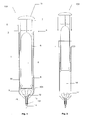
- FIG. 1 illustrates embodiments of a single use retractable syringe 100 that automatically retracts the needle with minimum force after the fluid within the syringe is dispensed so that the syringe can be safely disposed.
- This not only addresses needle stick injury by retracting the needle automatically with a minimum amount of force required for activation, but the syringe also has the ability to reduce the amount of dead or wasted space, namely the fluid left in the syringe after use, therefore minimising the chance of cross contamination by residual fluids.
- the syringe 100 has a barrel 1 that is largely tubular in shape and is formed to have a rearwardly open end 2 with a circular collar 5 to receive a plunger rod 6 and a forwardly end reduced in diameter to a central opening 102, namely closed end 3, that houses a needle holder 12.
- a hypodermic needle 14 is supported by the needle holder 12 and a spring 13 is compressed between the central opening 102 and needle holder 12.
- the syringe is designed to have at least part of needle holder 12 and a hypodermic needle 14 protruding and exposed past the most forward part of the barrel at the closed end 3.
- the barrel also has opposing finger grips 4 to allow a user to depress the plunger rod 6 against the barrel 1.
- the barrel 1 can be made as a single piece from injection moulded plastics for example, UV resistant high clarity polypropylene, or any other material typically used to make syringe barrels.
- the plunger rod 6 is largely tubular in shape and slides within barrel 1. It has a hollow retraction cavity 9 located inside the tubular form with an open end at a most forwardly portion 8 and has a closed end at rearwardly portion 7. The open end at the most forwardly section 8 is sealed by a plunger seal 11 attached around the outlet of the plunger rod 6.
- Plunger seal 11 also spans across the open end at forward portion 8. It slidingly seals inside the barrel 1 to form a variable fluid chamber 16 between plunger seal 11 and the closed end 3 of the barrel 1.
- An operational grip or thumb pad 10 on the closed end of plunger rod 6 provides a surface for a user to depress against finger grips 4 on the barrel 1.
- the plunger rod can be made as a single piece from injection moulded plastics, such as a polypropylene. Talc powder could be added to the plastics to give plunger rod 6 strength and an opaque appearance. Alternatively, the plunger rod 6 could be made in multiple parts, as discussed further below.
- the syringe 100 functions similarly to standard syringes in that a user draws up the fluid into the variable chamber 16 by placing the hypodermic needle 14 into a fluid filled vial (not shown) and pulling back on the plunger rod 6 from its position shown in Figure 1 using the thumb pad 10. This causes a vacuum to form in the variable chamber 16 of the syringe and fluid is drawn up through the hypodermic needle 14, through a fluid path 15 of the needle holder 12 and into the variable fluid chamber 16 of the syringe barrel 1.
- Figure 2 illustrates fluid chamber filled with liquid and the syringe prepared for injection.
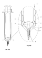
- Figures 3 (a) and 3 (b) illustrate the plunger rod 6 approaching the end of the injection stroke and plunger seal 11 coming into contact with the needle holder 12.
- the needle holder 12 has extended resilient arms 17 that protrude upward into variable fluid chamber 16, and the plunger seal 11 at the open end of the plunger has a sacrificial deformable membrane stretched across the open end which starts to stretch and conform around arms 17 as plunger rod 6 is pushed further against needle holder 12.
- the plunger seal 11 with its stretchable sacrificial membrane 18 can be moulded in one piece using an elastomeric material like Santoprene® which is commonly used in the syringe manufacturing industry and would preferably consist of a 181 type, 55 to 65 grade in order to obtain correct elasticity for best timing of plunger rod movement against the needle holder.
- Santoprene® which is commonly used in the syringe manufacturing industry and would preferably consist of a 181 type, 55 to 65 grade in order to obtain correct elasticity for best timing of plunger rod movement against the needle holder.
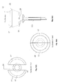
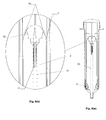
- Figures 4 (a) and 4 (b) illustrate the needle holder 12 with Figures 4 (a), 4 (c) and 4 (d) showing the needle holder 12 in an open condition before retraction and Figures 4 (b) and 4 (e) showing the needle holder 12 in a closed condition during the retraction process.
- Needle holder 12 comprises a long hollow holding section 103, which receives the hypodermic needle 14, connected to a resilient portion, namely the two semi-circular resilient arms 17.
- the needle holder 12 has scavenging ports 24 that are level or just below the most bottom part of the variable fluid chamber 16 of the barrel 1 maximising the amount of fluid that can be expelled before retraction, therefore reducing dead or waste space.
- the needle holder is held in a first, non-retracted position in the closed end 3 of barrel 1 by small outward facing locking barbs 23, which are formed as part of the needle holder at the base of the resilient arms 17.
- the locking barbs 23 are configured to engage the back of the internal locking groove 25 formed in the closed end 3 of barrel 1 and are designed to withstand all rearward forces, namely forces by spring 13 directed rearwardly of barrel 1.
- the needle holder 12 would only succumb to these rearwardly forces when the locking barbs 23 have been levered past the internal locking groove 25 in the closed end 3 of barrel (1) and when the stretchable sacrificial membrane has burst.
- a raised internal lip inside the closed end 3 of barrel 1 could be used rather than a groove and to receive a corresponding recess on the needle holder.
- Resilient arms 17 are biased away from each other inherently by their material.
- each arm 17 has an outer point, namely an apex 22, which is the outermost point across the resilient portion and which defines the maximum width of the resilient portion.
- the plunger rod has an internal sloped protruding surface on the wall of the hollow cavity 9, namely a triggering mechanism or trigger surface 20.
- a triggering mechanism or trigger surface 20 As plunger rod 6 is pushed in a downward direction toward the needle holder it starts to compress and close the needle holder's resilient arms 17. As this happens the apex 22 begins to automatically advance itself in an upwardly direction towards the plunger rod's trigger surface 20 and the apex of the trigger surface, namely trigger point 28. This process is defined as “self advancing needle holder timing”.
- Self advancing needle holder timing is where the apex 22 is urged to move up toward and into the hollow cavity 9 of plunger rod 6 (and specifically toward trigger point 28) as the plunger rod moves down and engages with the needle holder's resilient portion. This double acting movement between the resilient arms 17 and plunger rod 6 releases the engagement between the needle holder 12 and barrel 1 to allow spring 13 to push the needle holder through stretched membrane 18. Because the apex 22, which provides a leverage point for levering barbs 23 out of groove 25, moves towards the plunger rod, the effective length that the plunger rod travels to the end of the injection stroke is shorter than what it would be if apex 22 remained stationary.
- This advancement of apex 22 has two distinct advantages: one is that the plunger rod travels a shorter distance to activate the retraction sequence so the engagement of the retraction mechanism is able to take place when the plunger rod is closer to the end of the injection stroke without compromising the force required to activate the syringe; the second advantage is that the retraction sequence is delayed to the last possible moment of the injection stroke and thus the fluid integrity of the syringe remains intact closer to the point of retraction, which minimises the chance of destabilizing the needle holder and the sealing arrangements by avoiding hydraulic dynamics that can cause premature activation and leaking by hydraulic forces.
- needle holder 12 It would be desirable for needle holder 12 to be made as a single part from a injection mouldable plastics such as polypropylene.
- a polystyrene could also be used because of its ability to be able to use a UV curable glue to attach a stainless hypodermic needle without having to prepare the surface of needle holder 12.
- the mechanical advantage and mechanical leverage the needle holder has over the locking barbs 23 can be changed and increased by moving the distance of apex 22 further away from locking barbs 23 than that illustrated in the drawings. This would give greater mechanical advantage by the needle holder resilient arms 17 over the locking barbs 23 and thereby reduce activation force without compromising the force required to hold the needle holder 12 against the bias of the compressed spring 13 and other forces, such as pushing the needle into the thick rubber bung of a medical vial.
- Locking barbs 23 could be designed to fracture or break by placing a weakening groove 26 on the forward side of the locking barbs 23 in order to further reduce the activation force and also not allowing the needle holder to be refitted into a non-retracting position after use therefore making syringe 100 self-destructing and non-reusable.
- the needle holder 12 is held in place in the closed end 3 of barrel 1 by mechanical means it is not adversely affected by the hydraulic dynamics that cause premature activation, and namely by hydraulic forces that are generated by depressing the plunger rod 6 and forcing the fluid in the variable fluid chamber 16 into the smaller diameter of the needle holder fluid path 15.
- Figure 5 (a) and 5 (b) illustrate the plunger rod 6 travelling further towards the end of the injection stroke.
- Outer inclined surfaces 19 of the resilient arms 17 above apex 22 begin to force the stretchable sacrificial membrane 18 of the plunger seal 11 against the trigger surface 20 as the plunger rod continues to travel downwardly towards the central opening 102.
- the trigger surface 20 forces the resilient arms 17 to close together.
- a forward part 21 of the plunger seal is designed to roll inwardly towards the needle holder while the seal is being stretched.
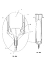
- FIGS 6 (a) and 6 (b) illustrate the plunger rod 6 has been depressed and is coming to the end of the injection stroke.
- the needle holder locking barbs 23 have now been levered out of the internal locking groove 25 due to the compression of resilient arms 17, which are forced together by the trigger surface 20 as the plunger rod reaches the end of the injection stroke.
- the resilient arms' apex 22 and trigger point 28 of the trigger surface 20 are now level and the resilient arms 17 have now closed together and the only thing holding the needle holder 12 against the closed end of the barrel 1 is the sacrificial membrane 18 that has been stretched to almost its limit.
- the syringe is mechanically in automatic retracting mode.
- forward part of the plunger seal 21 of plunger seal 11 is rolls inwardly towards the needle holder 12.
- forward part 21 conforms to the shape of the needle holder and channels the last of the fluid in the variable fluid chamber 16 into the fluid scavenging ports 24 and out through the needle holder fluid path 15.
- Figure 7 (a) and 7 (b) show the plunger rod 6 with the plunger seal 11 coming to the end of the injection stroke and forward part 21 of the plunger seal draws even closer to the needle holder 12.
- the front part of the plunger seal which covers the end walls of the forward section 8 of plunger rod 6 comes to rest on a front wall 104 of the closed end 3 of barrel 1 thereby expelling all of fluid from the variable fluid chamber as the stretchable sacrificial membrane 18 is now stretched to the point that it can no longer withstand the biasing force of the compressed spring 13.
- Figures 8 (a) and 8 (b) illustrate the point where the stretchable sacrificial membrane 18 has burst and the needle holder apex 22 is above the trigger point 28. This causes the needle holder needle holder 12 with the hypodermic needle 14 attached to it to automatically pass through into the retraction cavity 9 propelled by the spring 13.
- Figures 9 (a) and 9 (b) illustrate the needle holder 12 and hypodermic needle 14 retracted into the hollow plunge rod and retained in the rearward section 7 of the plunger rod 6 by expanded spring 13.
- retraction cavity restraining stops 29 are mounted inside of the rearward 5 section 7. The needle holder 12 can pass by the stops 29 but is prevented from returning so that the hypodermic needle 14 remains safely inside the retraction cavity 9 leaving only a small portion of the spring 13 as the only part of the retraction mechanism left inside the closed end 3 of the barrel 1 after retraction the hypodermic needle therefore no longer poses a threat to anyone and is unable to be reused.
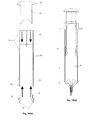
- Figures 10 (a) and 10 (b) are illustrations of an alternative embodiment of the single-use retractable syringe. While it is desirable to have as few parts as possible in order to have a syringe that is reliable and cost effective to mass produce, some components can include multiple parts, particularly if this enhances features of the syringe at a minimal cost and without affecting the mechanical reliability of the syringe.
- the plunger rod 6 is made in three pieces and consists of a plunger rod barrel, a detachable trigger piece 35 and a detachable operational grip 34 with thumb pad.
- Plunger rod barrel 30 is largely tubular in shape and could be made as a single piece from injection moulded plastics such as a polypropylene. Talc powder or the like could be added to the polypropylene to give the barrel 30 added strength and an opaque appearance.
- the plunger rod barrel 30 is similar in configuration to plunger rod 6 of the previous embodiment but includes internal locking grooves or barbs 33 located inside a forward section 31 and a rearward section 32 of barrel 30 to receive by engagement the detachable internal trigger piece 35 at the forward section 31, and the operational grip 34 at the and retained in the rearward section 7 of the plunger rod 6 by expanded spring 13.
- retraction cavity restraining stops 29 are mounted inside of the rearward section 7.
- the needle holder 12 can pass by the stops 29 but is prevented from returning so that the hypodermic needle 14 remains safely inside the retraction cavity 9 leaving only a small portion of the spring 13 as the only part of the retraction mechanism left inside the closed end 3 of the barrel 1 after retraction the hypodermic needle therefore no longer poses a threat to anyone and is unable to be reused.
- Figures 10 (a) and 10 (b) are illustrations of an alternative embodiment of the single-use retractable syringe. While it is desirable to have as few parts as possible in order to have a syringe that is reliable and cost effective to mass produce, some components can include multiple parts, particularly if this enhances features of the syringe at a minimal cost and without affecting the mechanical reliability of the syringe.
- the plunger rod 6 is made in three pieces and consists of a plunger rod barrel, a detachable trigger piece 35 and a detachable operational grip 34 with thumb pad.
- Plunger rod barrel 30 is largely tubular in shape and could be made as a single piece from injection moulded plastics such as a polypropylene. Talc powder or the like could be added to the polypropylene to give the barrel 30 added strength and an opaque appearance.
- the plunger rod barrel 30 is similar in configuration to plunger rod 6 of the previous embodiment but includes internal locking grooves or barbs 33 located inside a forward section 31 and a rearward section 32 of barrel 30 to receive by engagement the detachable internal trigger piece 35 at the forward section 31, and the operational grip 34 at the rearward section 32. Aside from engagement with the barbs or grooves, the trigger piece 35 and grip 34 could be also attached by press fit or gluing.
- the trigger piece 35 is circular in shape and has a conical sloping interior that comes to a peak at an apex 28.
- the piece also has an annular shoulder 36 around the outside to engage with a corresponding circular groove in the plunger seal 11.
- a similar engagement between the trigger surface 20 and seal 11 exists for the previous embodiment of the syringe.
- the trigger piece 35 resists any rearward movement during the retraction process as the needle holder 12 propels past, trigger piece could be made as a single piece from injection mouldable plastics such as a polypropylene.
- An oil based type of injectable plastics such as Aseatoll® would be desirable because it has a high level of hardness and its oily characteristics would aid in lubrication between the trigger piece 35 and the stretchable sacrificial membrane 18 during the retraction process.
- the detachable operational grip 34 has a forward section 36 and a rearward section 37.
- the forward section is configured to be attached to the rearward section 32 of plunger rod barrel 30 either by press fit, gluing or engaging with the locking barbs or groves 33.
- the rearward section 37 is configured so that pressure applied to it by a user's thumb is evenly distributed which causes less pain to the user.
- One advantage of having a detachable operational grip or thumb pad rather than it being moulded with the rest of the plunger rod is the ability to replace the grip with one of a different colour.
- a procedure by the International Organization for Standardization (ISO) identifies different needle gauges by colour, for example a 21 gauge needle is identified by the colour green, in order that the connect needle can be identified quickly without the need to read the package.
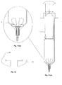
- Figures 11 (a) and 11 (b) illustrate a single use retractable syringe in yet another embodiment.
- the internal locking grooves at the closed end 3 of the barrel are carried by an annular insert 38 which is attached permanently or detachably to the closed end 3 of syringe barrel 1 by way of either gluing or engagement between locking barbs or grooves 33 as shown in Figures 11 (a) and 11 (b).
- Figures 11 (a) and 11 (b) show insert 38 being coloured. This would be helpful for the same reasons given above.
- the advantage of having both the grip and insert coloured is that the device can be colour coded at both ends.
- the coloured insert 38 can be made as a single piece from injection mouldable plastics for example polypropylene.
- Figures 13 (a) to 13 (d) illustrate another embodiment of a needle holder 60.
- the needle holding section 103 of the needle holder 60 is the same as the needle holder 12 of the first embodiment.
- the resilient aspect is however different.
- needle holders 12 and 60 are similar. However, rather than having broad semi-circular resilient arms as in needle holder 12, needle holder 60 has narrower arms 62, as best shown in the plan views of Figures 13 (c) and 13 (d) . Profile arms 64 also have an elbow defining the outwardly most point at apex 64 where the diameter of the needle holder 60 is largest, and which reacts against trigger surface 20, which has a smaller diameter, to compress resilient arms 62 and release needle holder 60 from engagement with the barrel 1.
- the syringe provides a means of a safe syringe injection with automatic and total needle retraction without causing the recipient additional pain, for example by depressing the plunger further than the end of the injection stroke in order to activate the retraction mechanism, which is required by some known syringes. Cross contamination by splatter is minimised and the syringe cannot be tampered with for re-use.
- Retraction mode starts before the plunger rod finishes the injection stroke by the needle holder's resilient arms beginning to advance in the opposite direction to the injection stroke and toward the trigger surface of the plunger rod.
- the timing of the plunger rod components and needle holder components is such that when all the fluid has been expelled from the variable chamber, the resilient arms lever out the needle holder's connection with the barrel so that the needle holder is no longer restrained by the barrel and is subjected to the full force of the spring to rupture through the stretched membrane and retract into the plunger rod.
Landscapes
- Health & Medical Sciences (AREA)
- Engineering & Computer Science (AREA)
- Heart & Thoracic Surgery (AREA)
- Vascular Medicine (AREA)
- Anesthesiology (AREA)
- Biomedical Technology (AREA)
- Environmental & Geological Engineering (AREA)
- Hematology (AREA)
- Life Sciences & Earth Sciences (AREA)
- Animal Behavior & Ethology (AREA)
- General Health & Medical Sciences (AREA)
- Public Health (AREA)
- Veterinary Medicine (AREA)
- Infusion, Injection, And Reservoir Apparatuses (AREA)
Applications Claiming Priority (1)
| Application Number | Priority Date | Filing Date | Title |
|---|---|---|---|
| AU2010901349A AU2010901349A0 (en) | 2010-03-31 | Syringe having a retractable needle |
Publications (1)
| Publication Number | Publication Date |
|---|---|
| EP2371407A1 true EP2371407A1 (en) | 2011-10-05 |
Family
ID=44278949
Family Applications (1)
| Application Number | Title | Priority Date | Filing Date |
|---|---|---|---|
| EP10194868A Withdrawn EP2371407A1 (en) | 2010-03-31 | 2010-12-14 | Syringe having a retractable needle |
Country Status (6)
| Country | Link |
|---|---|
| US (1) | US20110245768A1 (pt) |
| EP (1) | EP2371407A1 (pt) |
| AU (1) | AU2011202471A1 (pt) |
| BR (1) | BRPI1102898A2 (pt) |
| CA (1) | CA2742331A1 (pt) |
| ZA (1) | ZA201104078B (pt) |
Cited By (1)
| Publication number | Priority date | Publication date | Assignee | Title |
|---|---|---|---|---|
| WO2013067588A1 (en) * | 2011-11-09 | 2013-05-16 | Unitract Syringe Pty Ltd | Improved retractable syringe needle |
Families Citing this family (1)
| Publication number | Priority date | Publication date | Assignee | Title |
|---|---|---|---|---|
| US11975176B2 (en) | 2022-01-31 | 2024-05-07 | Numedico Technologies (Ip) Pty Ltd | Devices and methods for syringes configured to reduce or eliminate residual volume |
Citations (4)
| Publication number | Priority date | Publication date | Assignee | Title |
|---|---|---|---|---|
| WO1992011883A1 (en) * | 1990-12-28 | 1992-07-23 | Yulami Pty Ltd | Syringe device |
| US5605544A (en) * | 1996-02-12 | 1997-02-25 | Tsao; Chien-Hua | Safety injector with returnable needle |
| US6090077A (en) | 1995-05-11 | 2000-07-18 | Shaw; Thomas J. | Syringe plunger assembly and barrel |
| US20040116857A1 (en) * | 2001-05-22 | 2004-06-17 | Kiehne Bruce Leigh | Single use syringe |
-
2010
- 2010-12-06 US US12/960,775 patent/US20110245768A1/en not_active Abandoned
- 2010-12-14 EP EP10194868A patent/EP2371407A1/en not_active Withdrawn
-
2011
- 2011-05-26 AU AU2011202471A patent/AU2011202471A1/en not_active Abandoned
- 2011-06-01 ZA ZA2011/04078A patent/ZA201104078B/en unknown
- 2011-06-03 CA CA2742331A patent/CA2742331A1/en not_active Abandoned
- 2011-06-13 BR BRPI1102898-0A patent/BRPI1102898A2/pt not_active IP Right Cessation
Patent Citations (4)
| Publication number | Priority date | Publication date | Assignee | Title |
|---|---|---|---|---|
| WO1992011883A1 (en) * | 1990-12-28 | 1992-07-23 | Yulami Pty Ltd | Syringe device |
| US6090077A (en) | 1995-05-11 | 2000-07-18 | Shaw; Thomas J. | Syringe plunger assembly and barrel |
| US5605544A (en) * | 1996-02-12 | 1997-02-25 | Tsao; Chien-Hua | Safety injector with returnable needle |
| US20040116857A1 (en) * | 2001-05-22 | 2004-06-17 | Kiehne Bruce Leigh | Single use syringe |
Cited By (5)
| Publication number | Priority date | Publication date | Assignee | Title |
|---|---|---|---|---|
| WO2013067588A1 (en) * | 2011-11-09 | 2013-05-16 | Unitract Syringe Pty Ltd | Improved retractable syringe needle |
| CN103945884A (zh) * | 2011-11-09 | 2014-07-23 | 尤尼特拉克特注射器公司 | 改进的缩回式注射器针头 |
| AU2012334816B2 (en) * | 2011-11-09 | 2016-03-10 | Unitract Syringe Pty Ltd | Improved retractable syringe needle |
| US9604010B2 (en) | 2011-11-09 | 2017-03-28 | Unitract Syringe Pty Ltd | Retractable syringe needle |
| CN103945884B (zh) * | 2011-11-09 | 2017-04-05 | 尤尼特拉克特注射器公司 | 改进的缩回式注射器针头 |
Also Published As
| Publication number | Publication date |
|---|---|
| US20110245768A1 (en) | 2011-10-06 |
| CA2742331A1 (en) | 2012-06-06 |
| ZA201104078B (en) | 2012-02-29 |
| AU2011202471A1 (en) | 2011-10-20 |
| BRPI1102898A2 (pt) | 2013-03-26 |
Similar Documents
| Publication | Publication Date | Title |
|---|---|---|
| US8721599B2 (en) | Dual chamber passive retraction needle syringe | |
| EP2313135B1 (en) | A retractable syringe | |
| CA2354786C (en) | Hypodermic syringe with selectively retractable needle | |
| US9486582B2 (en) | Automatic injection device with temporizing means | |
| US4966593A (en) | Disposable hypodermic syringe with retractable needle | |
| US20030144627A1 (en) | Spring launched needle safety clip | |
| US9272097B2 (en) | Retractable safety syringe with non-loaded seal | |
| US20070250003A1 (en) | Fluid activated retractable safety syringe | |
| US20130079718A1 (en) | Automatic injection device | |
| WO2012012783A1 (en) | Retractable safety syringe with non-loaded seal | |
| RU2359709C2 (ru) | Шприц фиксированной дозы с ограничением всасывания | |
| US20110245768A1 (en) | Syringe having a retractable needle | |
| EP1386628A2 (en) | Pre-filled retractable needle injection device |
Legal Events
| Date | Code | Title | Description |
|---|---|---|---|
| PUAI | Public reference made under article 153(3) epc to a published international application that has entered the european phase |
Free format text: ORIGINAL CODE: 0009012 |
|
| AK | Designated contracting states |
Kind code of ref document: A1 Designated state(s): AL AT BE BG CH CY CZ DE DK EE ES FI FR GB GR HR HU IE IS IT LI LT LU LV MC MK MT NL NO PL PT RO RS SE SI SK SM TR |
|
| AX | Request for extension of the european patent |
Extension state: BA ME |
|
| STAA | Information on the status of an ep patent application or granted ep patent |
Free format text: STATUS: THE APPLICATION IS DEEMED TO BE WITHDRAWN |
|
| 18D | Application deemed to be withdrawn |
Effective date: 20120406 |