EP2371409A1 - Insufflation de cavités corporelles - Google Patents
Insufflation de cavités corporelles Download PDFInfo
- Publication number
- EP2371409A1 EP2371409A1 EP10394006A EP10394006A EP2371409A1 EP 2371409 A1 EP2371409 A1 EP 2371409A1 EP 10394006 A EP10394006 A EP 10394006A EP 10394006 A EP10394006 A EP 10394006A EP 2371409 A1 EP2371409 A1 EP 2371409A1
- Authority
- EP
- European Patent Office
- Prior art keywords
- connector
- aerosol
- insufflation gas
- insufflation
- mixing chamber
- Prior art date
- Legal status (The legal status is an assumption and is not a legal conclusion. Google has not performed a legal analysis and makes no representation as to the accuracy of the status listed.)
- Withdrawn
Links
- 239000000443 aerosol Substances 0.000 claims abstract description 131
- 238000000034 method Methods 0.000 claims abstract description 26
- 230000009467 reduction Effects 0.000 claims abstract description 6
- 239000007788 liquid Substances 0.000 claims description 29
- 239000012530 fluid Substances 0.000 claims description 25
- 239000006193 liquid solution Substances 0.000 abstract description 20
- 239000000203 mixture Substances 0.000 abstract description 6
- 238000002357 laparoscopic surgery Methods 0.000 abstract description 5
- 206010019909 Hernia Diseases 0.000 abstract description 2
- 210000003281 pleural cavity Anatomy 0.000 abstract description 2
- 230000008439 repair process Effects 0.000 abstract description 2
- 239000007789 gas Substances 0.000 description 80
- 239000003814 drug Substances 0.000 description 28
- 239000003795 chemical substances by application Substances 0.000 description 12
- 239000006199 nebulizer Substances 0.000 description 11
- 229940079593 drug Drugs 0.000 description 10
- 238000001356 surgical procedure Methods 0.000 description 9
- CURLTUGMZLYLDI-UHFFFAOYSA-N Carbon dioxide Chemical compound O=C=O CURLTUGMZLYLDI-UHFFFAOYSA-N 0.000 description 8
- 239000002245 particle Substances 0.000 description 8
- 210000001015 abdomen Anatomy 0.000 description 6
- FAPWRFPIFSIZLT-UHFFFAOYSA-M Sodium chloride Chemical compound [Na+].[Cl-] FAPWRFPIFSIZLT-UHFFFAOYSA-M 0.000 description 5
- 230000001225 therapeutic effect Effects 0.000 description 5
- 208000004550 Postoperative Pain Diseases 0.000 description 4
- 230000002924 anti-infective effect Effects 0.000 description 4
- 230000003110 anti-inflammatory effect Effects 0.000 description 4
- 230000008901 benefit Effects 0.000 description 4
- 229910002092 carbon dioxide Inorganic materials 0.000 description 4
- 239000012829 chemotherapy agent Substances 0.000 description 4
- 230000000694 effects Effects 0.000 description 4
- 239000011780 sodium chloride Substances 0.000 description 4
- 208000005646 Pneumoperitoneum Diseases 0.000 description 3
- 230000003444 anaesthetic effect Effects 0.000 description 3
- 230000001093 anti-cancer Effects 0.000 description 3
- 239000001569 carbon dioxide Substances 0.000 description 3
- 238000005516 engineering process Methods 0.000 description 3
- 238000010438 heat treatment Methods 0.000 description 3
- 150000003839 salts Chemical class 0.000 description 3
- XLYOFNOQVPJJNP-UHFFFAOYSA-N water Chemical compound O XLYOFNOQVPJJNP-UHFFFAOYSA-N 0.000 description 3
- RZVAJINKPMORJF-UHFFFAOYSA-N Acetaminophen Chemical compound CC(=O)NC1=CC=C(O)C=C1 RZVAJINKPMORJF-UHFFFAOYSA-N 0.000 description 2
- IJGRMHOSHXDMSA-UHFFFAOYSA-N Atomic nitrogen Chemical compound N#N IJGRMHOSHXDMSA-UHFFFAOYSA-N 0.000 description 2
- 102000002002 Neurokinin-1 Receptors Human genes 0.000 description 2
- 108010040718 Neurokinin-1 Receptors Proteins 0.000 description 2
- 230000004075 alteration Effects 0.000 description 2
- 230000000202 analgesic effect Effects 0.000 description 2
- RWZYAGGXGHYGMB-UHFFFAOYSA-N anthranilic acid Chemical compound NC1=CC=CC=C1C(O)=O RWZYAGGXGHYGMB-UHFFFAOYSA-N 0.000 description 2
- 239000003242 anti bacterial agent Substances 0.000 description 2
- -1 anti-infectives Substances 0.000 description 2
- 239000002260 anti-inflammatory agent Substances 0.000 description 2
- 229960005475 antiinfective agent Drugs 0.000 description 2
- 230000015572 biosynthetic process Effects 0.000 description 2
- 239000000919 ceramic Substances 0.000 description 2
- 230000008859 change Effects 0.000 description 2
- 238000010276 construction Methods 0.000 description 2
- 230000001419 dependent effect Effects 0.000 description 2
- 230000008020 evaporation Effects 0.000 description 2
- 238000001704 evaporation Methods 0.000 description 2
- BQJCRHHNABKAKU-KBQPJGBKSA-N morphine Chemical compound O([C@H]1[C@H](C=C[C@H]23)O)C4=C5[C@@]12CCN(C)[C@@H]3CC5=CC=C4O BQJCRHHNABKAKU-KBQPJGBKSA-N 0.000 description 2
- 230000000069 prophylactic effect Effects 0.000 description 2
- 230000003637 steroidlike Effects 0.000 description 2
- 238000012546 transfer Methods 0.000 description 2
- 238000003466 welding Methods 0.000 description 2
- KIUKXJAPPMFGSW-DNGZLQJQSA-N (2S,3S,4S,5R,6R)-6-[(2S,3R,4R,5S,6R)-3-Acetamido-2-[(2S,3S,4R,5R,6R)-6-[(2R,3R,4R,5S,6R)-3-acetamido-2,5-dihydroxy-6-(hydroxymethyl)oxan-4-yl]oxy-2-carboxy-4,5-dihydroxyoxan-3-yl]oxy-5-hydroxy-6-(hydroxymethyl)oxan-4-yl]oxy-3,4,5-trihydroxyoxane-2-carboxylic acid Chemical compound CC(=O)N[C@H]1[C@H](O)O[C@H](CO)[C@@H](O)[C@@H]1O[C@H]1[C@H](O)[C@@H](O)[C@H](O[C@H]2[C@@H]([C@@H](O[C@H]3[C@@H]([C@@H](O)[C@H](O)[C@H](O3)C(O)=O)O)[C@H](O)[C@@H](CO)O2)NC(C)=O)[C@@H](C(O)=O)O1 KIUKXJAPPMFGSW-DNGZLQJQSA-N 0.000 description 1
- ZKMNUMMKYBVTFN-HNNXBMFYSA-N (S)-ropivacaine Chemical compound CCCN1CCCC[C@H]1C(=O)NC1=C(C)C=CC=C1C ZKMNUMMKYBVTFN-HNNXBMFYSA-N 0.000 description 1
- LEBVLXFERQHONN-UHFFFAOYSA-N 1-butyl-N-(2,6-dimethylphenyl)piperidine-2-carboxamide Chemical compound CCCCN1CCCCC1C(=O)NC1=C(C)C=CC=C1C LEBVLXFERQHONN-UHFFFAOYSA-N 0.000 description 1
- PDFKFLNYRFAWOA-UHFFFAOYSA-N 1-fluoroquinolin-2-one Chemical compound C1=CC=C2C=CC(=O)N(F)C2=C1 PDFKFLNYRFAWOA-UHFFFAOYSA-N 0.000 description 1
- BSYNRYMUTXBXSQ-UHFFFAOYSA-N Aspirin Chemical compound CC(=O)OC1=CC=CC=C1C(O)=O BSYNRYMUTXBXSQ-UHFFFAOYSA-N 0.000 description 1
- 229930186147 Cephalosporin Natural products 0.000 description 1
- 206010053567 Coagulopathies Diseases 0.000 description 1
- HEFNNWSXXWATRW-UHFFFAOYSA-N Ibuprofen Chemical compound CC(C)CC1=CC=C(C(C)C(O)=O)C=C1 HEFNNWSXXWATRW-UHFFFAOYSA-N 0.000 description 1
- NNJVILVZKWQKPM-UHFFFAOYSA-N Lidocaine Chemical compound CCN(CC)CC(=O)NC1=C(C)C=CC=C1C NNJVILVZKWQKPM-UHFFFAOYSA-N 0.000 description 1
- CMWTZPSULFXXJA-UHFFFAOYSA-N Naproxen Natural products C1=C(C(C)C(O)=O)C=CC2=CC(OC)=CC=C21 CMWTZPSULFXXJA-UHFFFAOYSA-N 0.000 description 1
- BRUQQQPBMZOVGD-XFKAJCMBSA-N Oxycodone Chemical compound O=C([C@@H]1O2)CC[C@@]3(O)[C@H]4CC5=CC=C(OC)C2=C5[C@@]13CCN4C BRUQQQPBMZOVGD-XFKAJCMBSA-N 0.000 description 1
- 208000002193 Pain Diseases 0.000 description 1
- 239000002202 Polyethylene glycol Substances 0.000 description 1
- 239000004098 Tetracycline Substances 0.000 description 1
- 229960001138 acetylsalicylic acid Drugs 0.000 description 1
- 230000009471 action Effects 0.000 description 1
- 238000004026 adhesive bonding Methods 0.000 description 1
- 238000012387 aerosolization Methods 0.000 description 1
- 239000000556 agonist Substances 0.000 description 1
- 229930013930 alkaloid Natural products 0.000 description 1
- 229940100198 alkylating agent Drugs 0.000 description 1
- 239000002168 alkylating agent Substances 0.000 description 1
- 229940126575 aminoglycoside Drugs 0.000 description 1
- 229940124326 anaesthetic agent Drugs 0.000 description 1
- 229940035676 analgesics Drugs 0.000 description 1
- 239000004037 angiogenesis inhibitor Substances 0.000 description 1
- 239000000730 antalgic agent Substances 0.000 description 1
- 229940045799 anthracyclines and related substance Drugs 0.000 description 1
- 230000002280 anti-androgenic effect Effects 0.000 description 1
- 229940046836 anti-estrogen Drugs 0.000 description 1
- 230000001833 anti-estrogenic effect Effects 0.000 description 1
- 229940121363 anti-inflammatory agent Drugs 0.000 description 1
- 238000011861 anti-inflammatory therapy Methods 0.000 description 1
- 230000000340 anti-metabolite Effects 0.000 description 1
- 230000000845 anti-microbial effect Effects 0.000 description 1
- 230000000259 anti-tumor effect Effects 0.000 description 1
- 239000000051 antiandrogen Substances 0.000 description 1
- 229940030495 antiandrogen sex hormone and modulator of the genital system Drugs 0.000 description 1
- 229940088710 antibiotic agent Drugs 0.000 description 1
- 229940121375 antifungal agent Drugs 0.000 description 1
- 229940100197 antimetabolite Drugs 0.000 description 1
- 239000002256 antimetabolite Substances 0.000 description 1
- 239000004599 antimicrobial Substances 0.000 description 1
- 229940045719 antineoplastic alkylating agent nitrosoureas Drugs 0.000 description 1
- ATALOFNDEOCMKK-OITMNORJSA-N aprepitant Chemical compound O([C@@H]([C@@H]1C=2C=CC(F)=CC=2)O[C@H](C)C=2C=C(C=C(C=2)C(F)(F)F)C(F)(F)F)CCN1CC1=NNC(=O)N1 ATALOFNDEOCMKK-OITMNORJSA-N 0.000 description 1
- 229960001372 aprepitant Drugs 0.000 description 1
- 239000003886 aromatase inhibitor Substances 0.000 description 1
- 229940046844 aromatase inhibitors Drugs 0.000 description 1
- 230000001580 bacterial effect Effects 0.000 description 1
- 230000003115 biocidal effect Effects 0.000 description 1
- 238000009530 blood pressure measurement Methods 0.000 description 1
- 230000036760 body temperature Effects 0.000 description 1
- 229960003150 bupivacaine Drugs 0.000 description 1
- 229940022399 cancer vaccine Drugs 0.000 description 1
- 238000009566 cancer vaccine Methods 0.000 description 1
- 230000000747 cardiac effect Effects 0.000 description 1
- RZEKVGVHFLEQIL-UHFFFAOYSA-N celecoxib Chemical compound C1=CC(C)=CC=C1C1=CC(C(F)(F)F)=NN1C1=CC=C(S(N)(=O)=O)C=C1 RZEKVGVHFLEQIL-UHFFFAOYSA-N 0.000 description 1
- 229960000590 celecoxib Drugs 0.000 description 1
- 229940124587 cephalosporin Drugs 0.000 description 1
- 150000001780 cephalosporins Chemical class 0.000 description 1
- 230000035602 clotting Effects 0.000 description 1
- 238000004891 communication Methods 0.000 description 1
- 230000003750 conditioning effect Effects 0.000 description 1
- 239000000356 contaminant Substances 0.000 description 1
- 230000036757 core body temperature Effects 0.000 description 1
- 239000003246 corticosteroid Substances 0.000 description 1
- 229960001334 corticosteroids Drugs 0.000 description 1
- 229940111134 coxibs Drugs 0.000 description 1
- 239000003255 cyclooxygenase 2 inhibitor Substances 0.000 description 1
- 230000008021 deposition Effects 0.000 description 1
- 238000001514 detection method Methods 0.000 description 1
- XYYVYLMBEZUESM-UHFFFAOYSA-N dihydrocodeine Natural products C1C(N(CCC234)C)C2C=CC(=O)C3OC2=C4C1=CC=C2OC XYYVYLMBEZUESM-UHFFFAOYSA-N 0.000 description 1
- 230000003292 diminished effect Effects 0.000 description 1
- 239000006185 dispersion Substances 0.000 description 1
- 238000009826 distribution Methods 0.000 description 1
- 239000003534 dna topoisomerase inhibitor Substances 0.000 description 1
- 230000009977 dual effect Effects 0.000 description 1
- 239000000328 estrogen antagonist Substances 0.000 description 1
- 238000001914 filtration Methods 0.000 description 1
- 230000005484 gravity Effects 0.000 description 1
- 239000001307 helium Substances 0.000 description 1
- 229910052734 helium Inorganic materials 0.000 description 1
- SWQJXJOGLNCZEY-UHFFFAOYSA-N helium atom Chemical compound [He] SWQJXJOGLNCZEY-UHFFFAOYSA-N 0.000 description 1
- 238000001794 hormone therapy Methods 0.000 description 1
- 229920002674 hyaluronan Polymers 0.000 description 1
- 229960003160 hyaluronic acid Drugs 0.000 description 1
- LLPOLZWFYMWNKH-CMKMFDCUSA-N hydrocodone Chemical compound C([C@H]1[C@H](N(CC[C@@]112)C)C3)CC(=O)[C@@H]1OC1=C2C3=CC=C1OC LLPOLZWFYMWNKH-CMKMFDCUSA-N 0.000 description 1
- 229960000240 hydrocodone Drugs 0.000 description 1
- OROGSEYTTFOCAN-UHFFFAOYSA-N hydrocodone Natural products C1C(N(CCC234)C)C2C=CC(O)C3OC2=C4C1=CC=C2OC OROGSEYTTFOCAN-UHFFFAOYSA-N 0.000 description 1
- 229960001680 ibuprofen Drugs 0.000 description 1
- 230000001900 immune effect Effects 0.000 description 1
- 208000015181 infectious disease Diseases 0.000 description 1
- 239000003112 inhibitor Substances 0.000 description 1
- 230000010354 integration Effects 0.000 description 1
- 229960004194 lidocaine Drugs 0.000 description 1
- 229960005015 local anesthetics Drugs 0.000 description 1
- 230000013011 mating Effects 0.000 description 1
- 230000007246 mechanism Effects 0.000 description 1
- 238000002483 medication Methods 0.000 description 1
- 238000002324 minimally invasive surgery Methods 0.000 description 1
- 230000000394 mitotic effect Effects 0.000 description 1
- 238000003032 molecular docking Methods 0.000 description 1
- 238000012806 monitoring device Methods 0.000 description 1
- 229960005181 morphine Drugs 0.000 description 1
- 229960002009 naproxen Drugs 0.000 description 1
- CMWTZPSULFXXJA-VIFPVBQESA-N naproxen Chemical compound C1=C([C@H](C)C(O)=O)C=CC2=CC(OC)=CC=C21 CMWTZPSULFXXJA-VIFPVBQESA-N 0.000 description 1
- 229910052757 nitrogen Inorganic materials 0.000 description 1
- VIKNJXKGJWUCNN-XGXHKTLJSA-N norethisterone Chemical compound O=C1CC[C@@H]2[C@H]3CC[C@](C)([C@](CC4)(O)C#C)[C@@H]4[C@@H]3CCC2=C1 VIKNJXKGJWUCNN-XGXHKTLJSA-N 0.000 description 1
- 210000000056 organ Anatomy 0.000 description 1
- 229960002085 oxycodone Drugs 0.000 description 1
- 229960005489 paracetamol Drugs 0.000 description 1
- 150000003904 phospholipids Chemical class 0.000 description 1
- 229920001223 polyethylene glycol Polymers 0.000 description 1
- 229920001296 polysiloxane Polymers 0.000 description 1
- 230000008569 process Effects 0.000 description 1
- 230000001012 protector Effects 0.000 description 1
- 230000004044 response Effects 0.000 description 1
- 229960001549 ropivacaine Drugs 0.000 description 1
- 229920006395 saturated elastomer Polymers 0.000 description 1
- 238000012163 sequencing technique Methods 0.000 description 1
- 239000008223 sterile water Substances 0.000 description 1
- 230000035882 stress Effects 0.000 description 1
- 239000000126 substance Substances 0.000 description 1
- 239000004094 surface-active agent Substances 0.000 description 1
- 230000009885 systemic effect Effects 0.000 description 1
- 229960002180 tetracycline Drugs 0.000 description 1
- 229930101283 tetracycline Natural products 0.000 description 1
- 235000019364 tetracycline Nutrition 0.000 description 1
- 150000003522 tetracyclines Chemical class 0.000 description 1
- 229940124597 therapeutic agent Drugs 0.000 description 1
- 229940044693 topoisomerase inhibitor Drugs 0.000 description 1
- NZHGWWWHIYHZNX-CSKARUKUSA-N tranilast Chemical compound C1=C(OC)C(OC)=CC=C1\C=C\C(=O)NC1=CC=CC=C1C(O)=O NZHGWWWHIYHZNX-CSKARUKUSA-N 0.000 description 1
- 229960005342 tranilast Drugs 0.000 description 1
- LLPOLZWFYMWNKH-UHFFFAOYSA-N trans-dihydrocodeinone Natural products C1C(N(CCC234)C)C2CCC(=O)C3OC2=C4C1=CC=C2OC LLPOLZWFYMWNKH-UHFFFAOYSA-N 0.000 description 1
- 229940121358 tyrosine kinase inhibitor Drugs 0.000 description 1
- 239000005483 tyrosine kinase inhibitor Substances 0.000 description 1
- 229910052724 xenon Inorganic materials 0.000 description 1
- FHNFHKCVQCLJFQ-UHFFFAOYSA-N xenon atom Chemical compound [Xe] FHNFHKCVQCLJFQ-UHFFFAOYSA-N 0.000 description 1
Images


Classifications
-
- A—HUMAN NECESSITIES
- A61—MEDICAL OR VETERINARY SCIENCE; HYGIENE
- A61M—DEVICES FOR INTRODUCING MEDIA INTO, OR ONTO, THE BODY; DEVICES FOR TRANSDUCING BODY MEDIA OR FOR TAKING MEDIA FROM THE BODY; DEVICES FOR PRODUCING OR ENDING SLEEP OR STUPOR
- A61M13/00—Insufflators for therapeutic or disinfectant purposes, i.e. devices for blowing a gas, powder or vapour into the body
-
- A—HUMAN NECESSITIES
- A61—MEDICAL OR VETERINARY SCIENCE; HYGIENE
- A61M—DEVICES FOR INTRODUCING MEDIA INTO, OR ONTO, THE BODY; DEVICES FOR TRANSDUCING BODY MEDIA OR FOR TAKING MEDIA FROM THE BODY; DEVICES FOR PRODUCING OR ENDING SLEEP OR STUPOR
- A61M11/00—Sprayers or atomisers specially adapted for therapeutic purposes
- A61M11/005—Sprayers or atomisers specially adapted for therapeutic purposes using ultrasonics
-
- A—HUMAN NECESSITIES
- A61—MEDICAL OR VETERINARY SCIENCE; HYGIENE
- A61M—DEVICES FOR INTRODUCING MEDIA INTO, OR ONTO, THE BODY; DEVICES FOR TRANSDUCING BODY MEDIA OR FOR TAKING MEDIA FROM THE BODY; DEVICES FOR PRODUCING OR ENDING SLEEP OR STUPOR
- A61M16/00—Devices for influencing the respiratory system of patients by gas treatment, e.g. ventilators; Tracheal tubes
- A61M16/08—Bellows; Connecting tubes ; Water traps; Patient circuits
- A61M16/0816—Joints or connectors
- A61M16/0833—T- or Y-type connectors, e.g. Y-piece
-
- B—PERFORMING OPERATIONS; TRANSPORTING
- B05—SPRAYING OR ATOMISING IN GENERAL; APPLYING FLUENT MATERIALS TO SURFACES, IN GENERAL
- B05B—SPRAYING APPARATUS; ATOMISING APPARATUS; NOZZLES
- B05B7/00—Spraying apparatus for discharge of liquids or other fluent materials from two or more sources, e.g. of liquid and air, of powder and gas
- B05B7/02—Spray pistols; Apparatus for discharge
- B05B7/04—Spray pistols; Apparatus for discharge with arrangements for mixing liquids or other fluent materials before discharge
- B05B7/0416—Spray pistols; Apparatus for discharge with arrangements for mixing liquids or other fluent materials before discharge with arrangements for mixing one gas and one liquid
- B05B7/0483—Spray pistols; Apparatus for discharge with arrangements for mixing liquids or other fluent materials before discharge with arrangements for mixing one gas and one liquid with gas and liquid jets intersecting in the mixing chamber
-
- A—HUMAN NECESSITIES
- A61—MEDICAL OR VETERINARY SCIENCE; HYGIENE
- A61M—DEVICES FOR INTRODUCING MEDIA INTO, OR ONTO, THE BODY; DEVICES FOR TRANSDUCING BODY MEDIA OR FOR TAKING MEDIA FROM THE BODY; DEVICES FOR PRODUCING OR ENDING SLEEP OR STUPOR
- A61M13/00—Insufflators for therapeutic or disinfectant purposes, i.e. devices for blowing a gas, powder or vapour into the body
- A61M13/003—Blowing gases other than for carrying powders, e.g. for inflating, dilating or rinsing
-
- A—HUMAN NECESSITIES
- A61—MEDICAL OR VETERINARY SCIENCE; HYGIENE
- A61M—DEVICES FOR INTRODUCING MEDIA INTO, OR ONTO, THE BODY; DEVICES FOR TRANSDUCING BODY MEDIA OR FOR TAKING MEDIA FROM THE BODY; DEVICES FOR PRODUCING OR ENDING SLEEP OR STUPOR
- A61M15/00—Inhalators
- A61M15/0086—Inhalation chambers
-
- A—HUMAN NECESSITIES
- A61—MEDICAL OR VETERINARY SCIENCE; HYGIENE
- A61M—DEVICES FOR INTRODUCING MEDIA INTO, OR ONTO, THE BODY; DEVICES FOR TRANSDUCING BODY MEDIA OR FOR TAKING MEDIA FROM THE BODY; DEVICES FOR PRODUCING OR ENDING SLEEP OR STUPOR
- A61M2202/00—Special media to be introduced, removed or treated
- A61M2202/02—Gases
- A61M2202/0225—Carbon oxides, e.g. Carbon dioxide
-
- A—HUMAN NECESSITIES
- A61—MEDICAL OR VETERINARY SCIENCE; HYGIENE
- A61M—DEVICES FOR INTRODUCING MEDIA INTO, OR ONTO, THE BODY; DEVICES FOR TRANSDUCING BODY MEDIA OR FOR TAKING MEDIA FROM THE BODY; DEVICES FOR PRODUCING OR ENDING SLEEP OR STUPOR
- A61M2202/00—Special media to be introduced, removed or treated
- A61M2202/02—Gases
- A61M2202/025—Helium
-
- A—HUMAN NECESSITIES
- A61—MEDICAL OR VETERINARY SCIENCE; HYGIENE
- A61M—DEVICES FOR INTRODUCING MEDIA INTO, OR ONTO, THE BODY; DEVICES FOR TRANSDUCING BODY MEDIA OR FOR TAKING MEDIA FROM THE BODY; DEVICES FOR PRODUCING OR ENDING SLEEP OR STUPOR
- A61M2202/00—Special media to be introduced, removed or treated
- A61M2202/02—Gases
- A61M2202/0266—Nitrogen (N)
-
- A—HUMAN NECESSITIES
- A61—MEDICAL OR VETERINARY SCIENCE; HYGIENE
- A61M—DEVICES FOR INTRODUCING MEDIA INTO, OR ONTO, THE BODY; DEVICES FOR TRANSDUCING BODY MEDIA OR FOR TAKING MEDIA FROM THE BODY; DEVICES FOR PRODUCING OR ENDING SLEEP OR STUPOR
- A61M2205/00—General characteristics of the apparatus
- A61M2205/75—General characteristics of the apparatus with filters
- A61M2205/7518—General characteristics of the apparatus with filters bacterial
-
- B—PERFORMING OPERATIONS; TRANSPORTING
- B05—SPRAYING OR ATOMISING IN GENERAL; APPLYING FLUENT MATERIALS TO SURFACES, IN GENERAL
- B05B—SPRAYING APPARATUS; ATOMISING APPARATUS; NOZZLES
- B05B12/00—Arrangements for controlling delivery; Arrangements for controlling the spray area
- B05B12/08—Arrangements for controlling delivery; Arrangements for controlling the spray area responsive to condition of liquid or other fluent material to be discharged, of ambient medium or of target ; responsive to condition of spray devices or of supply means, e.g. pipes, pumps or their drive means
- B05B12/081—Arrangements for controlling delivery; Arrangements for controlling the spray area responsive to condition of liquid or other fluent material to be discharged, of ambient medium or of target ; responsive to condition of spray devices or of supply means, e.g. pipes, pumps or their drive means responsive to the weight of a reservoir or container for liquid or other fluent material; responsive to level or volume of liquid or other fluent material in a reservoir or container
-
- B—PERFORMING OPERATIONS; TRANSPORTING
- B05—SPRAYING OR ATOMISING IN GENERAL; APPLYING FLUENT MATERIALS TO SURFACES, IN GENERAL
- B05B—SPRAYING APPARATUS; ATOMISING APPARATUS; NOZZLES
- B05B17/00—Apparatus for spraying or atomising liquids or other fluent materials, not covered by the preceding groups
- B05B17/04—Apparatus for spraying or atomising liquids or other fluent materials, not covered by the preceding groups operating with special methods
- B05B17/06—Apparatus for spraying or atomising liquids or other fluent materials, not covered by the preceding groups operating with special methods using ultrasonic or other kinds of vibrations
- B05B17/0607—Apparatus for spraying or atomising liquids or other fluent materials, not covered by the preceding groups operating with special methods using ultrasonic or other kinds of vibrations generated by electrical means, e.g. piezoelectric transducers
- B05B17/0638—Apparatus for spraying or atomising liquids or other fluent materials, not covered by the preceding groups operating with special methods using ultrasonic or other kinds of vibrations generated by electrical means, e.g. piezoelectric transducers spray being produced by discharging the liquid or other fluent material through a plate comprising a plurality of orifices
- B05B17/0646—Vibrating plates, i.e. plates being directly subjected to the vibrations, e.g. having a piezoelectric transducer attached thereto
-
- B—PERFORMING OPERATIONS; TRANSPORTING
- B05—SPRAYING OR ATOMISING IN GENERAL; APPLYING FLUENT MATERIALS TO SURFACES, IN GENERAL
- B05B—SPRAYING APPARATUS; ATOMISING APPARATUS; NOZZLES
- B05B17/00—Apparatus for spraying or atomising liquids or other fluent materials, not covered by the preceding groups
- B05B17/04—Apparatus for spraying or atomising liquids or other fluent materials, not covered by the preceding groups operating with special methods
- B05B17/06—Apparatus for spraying or atomising liquids or other fluent materials, not covered by the preceding groups operating with special methods using ultrasonic or other kinds of vibrations
- B05B17/0607—Apparatus for spraying or atomising liquids or other fluent materials, not covered by the preceding groups operating with special methods using ultrasonic or other kinds of vibrations generated by electrical means, e.g. piezoelectric transducers
- B05B17/0653—Details
- B05B17/0669—Excitation frequencies
Definitions
- Laparoscopic surgery also called minimally or less invasive surgery (MIS or LIS) or keyhole surgery is a modem surgical technique in which operations in the body are performed through small incisions as compared to the larger incisions needed in traditional surgical procedures.
- Gas such as carbon dioxide is delivered, via an insufflator, into a body cavity such as the abdomen leading to the formation of a pneumoperitoneum, thereby providing sufficient space for the surgeon to operate.
- the insufflator maintains the pneumoperitoneum and acts to renew the gas when leaks occur.
- insufflation gas conditioning systems suffer from one or more disadvantages including complexity of construction involving expensive monitoring devices, inaccurate control and/or difficulties in using them in a controlled working environment.
- HME heat moisture exchangers
- This invention is directed towards providing an improved method and an apparatus for use in insufflation.
- a connector for an insufflation system comprising a housing having a mixing chamber, an insufflator gas inlet to the mixing chamber, an aerosolised liquid inlet to the mixing chamber, an outlet for delivery of insufflation gas with aerosolised liquid entrained therein, the connector causing a substantial reduction in the velocity of insufflation gas from the insufflation gas inlet as it enters the mixing chamber and causing an increase in the velocity of the insufflation gas with entrained aerosol between the mixing chamber and the outlet.
- the connector comprises a tapered portion leading from the mixing chamber to the outlet.
- the taper angle ⁇ of the tapered portion may be between about 10° and 30°.
- the tapered portion has an entry with a first internal diameter (D 1 ) adjacent to the mixing chamber and a second internal diameter (D 2 ) at the outlet and the ratio of the first diameter to the second diameter is at least 2:1,at least 3:1,at least 4:1,at least 5:1.
- the distance between the taper entry and the outlet defines a length (L) and the ratio of the length to the first diameter D 1 may be at least 2:1, at least 3:1, at least 4:1.
- a central longitudinal axis L 1 at the insufflation gas inlet is coaxial with a central longitudinal axis L 0 at the outlet.
- a central longitudinal axis L 1 at the insufflation gas inlet may be above a central longitudinal axis L 0 at the outlet.
- the connector comprises a mounting leg for mounting an aerosol generator device to the connector. There may be an interlock between the connector mounting leg and the aerosol generator device.
- the mounting leg is angled towards the inlet of the connector.
- the mounting leg may be offset from a vertical axis by a tilt angle of at least 10°. Said tilt angle may be about 15°.
- the invention also provides an apparatus from use in insufflation comprising a connector of the invention and an aerosol generator for aerosolising a liquid and entraining the aerosol within an insufflation gas.
- the aerosol generator comprises a vibratable member having a plurality of apertures extending between a first surface and a second surface.
- the first surface may be adapted to receive the fluid to be aerosolised.
- the aerosol generator may be configured to generate an aerosol at the second surface.
- the vibratable member is dome-shaped in geometry.
- the vibratable member may comprise a stretched flat shape.
- the vibratable member may comprise a piezoelectric element.
- the apertures in the vibratable member are sized to aerosolise the first fluid by ejecting droplets of the first fluid such that the majority of the droplets by mass have a size of less than 5 micrometers.
- the apertures in the vibratable member may be sized to aerosolise the first fluid by ejecting droplets of the first fluid such that the majority of the droplets by mass have a size of less than 3 micrometers.
- the apertures in the vibratable member may be sized to aerosolise the first fluid by ejecting droplets of the first fluid such that the majority of the droplets by mass have a size in one range of less than 10 micrometers.
- a range band may be from I to 3 micrometers.
- a range band may be from 7 to 9 micrometers.
- the apparatus comprises a controller to control the operation of the aerosol generator.
- the controller may be configured to control the flow rate of the fluid to be aerosolised.
- the controller may be configured to deliver different flow rates of aerosol at different stages of a surgical procedure.
- the controller may be configured to deliver full flow at the start and/or end of a procedure.
- the controller may be configured to deliver reduced flow during a procedure.
- the controller may be set to deliver a pre-set amount of aerosol into insufflation gas.
- the apparatus may comprise means for varying the pre-set amount of aerosol.
- the means for varying the pre-set amount of aerosol may in one case comprise a user interface such as a keypad or switch.
- the controller may be configured to control operation of the aerosol generator responsive to the insufflation gas.
- controller is configured to control operation of the aerosol generator responsive to the flow rate of the insufflation gas.
- the apparatus comprises a device to determine the fluid flow rate of the insufflation gas.
- the determining device may comprise a flow sensor such as a flowmeter.
- the device to determine the fluid flow rate may comprise a differential pressure sensor.
- the apparatus comprises a humidity meter to measure the level of humidification of the insufflation gas.
- the invention provides a method for carrying out a procedure involving insufflation comprising the steps of:
- the method comprises the step of delivering the entrained fluid and insufflation gas into the body to insufflate at least part of the body.
- the fluid may be a liquid solution.
- the liquid solution may be saline having a salt concentration of greater than 1 ⁇ M.
- the fluid contains a therapeutic and/or prophylactic agent.
- the agent may be one or more selected from the group comprising an analgestic, an anti-inflammatory, an anti-infective, an anaesthetic, an anticancer chemotherapy agent, and an anti-adhesion agent.
- the procedure is a laparascopic procedure.
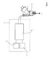
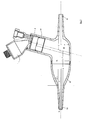
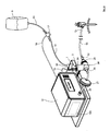
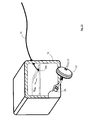
- FIG. 1 there is illustrated an apparatus according to the invention for use in insufflation of a body cavity 5, in this case through a trocar 6.
- a body cavity such as in arthroscopies, pleural cavity insufflation (for example during thoracoscopy), retroperitoneal insufflations (for example retroperitoneoscopy), during hernia repair, during mediastinoscopy and any other such procedure involving insufflation.
- the apparatus comprises a reservoir 1 for storing an liquid solution, an aerosol generator 2 for aerosolising the solution, and a controller 3 for controlling operation of the aerosol generator 2.
- aerosolised liquid solution is entrained with insufflation gas.
- the gas is any suitable insufflation gas such as carbon dioxide.
- suitable insufflation gases are nitrogen, helium and xenon.
- the insufflation gas is delivered into an insufflation gas tubing 15 by an insufflator 12.
- the insufflator 12 may be of any suitable type such as those available from Karl Storz, Olympus and Stryker.
- the insufflator 12 has an outlet 20 through which insufflation gas is delivered.
- a bacterial filter (sometimes called a transducer protector ⁇ protecting the patient from insufflator contaminants and vice versa) 21 may be provided within the insufflator or, as illustrated, downstream of the insufflator outlet 20.
- the invention provides a connector, in this case a T-piece connector or housing 30 having an insufflation gas inlet 31 and an outlet 32.
- the connector 30 also comprises an aerosol supply conduit 34 for delivering the aerosol from the aerosol generator 2 into a mixing chamber 33 in which the aerosol is entrained with insufflation gas.
- the aerosol insufflation gas mixture passes out of the connector 30 through the outlet 32 and is delivered along the insufflation gas conduit 15 to the trocar 6 for delivery into a body cavity 5.
- the connector 30 causes a substantial sudden reduction in the velocity of the insufflation gas from the insufflation gas inlet as it enters the mixing chamber 33.
- the connector 30 also causes a gradual increase in the velocity of the insufflation gas with entrained aerosol between the mixing chamber 33 and the outlet 32.
- the connector 30 comprises a tapered portion 35 leading from the mixing chamber to the outlet.
- the taper angle ⁇ ( Fig. 7 ) of the tapered portion 35 is between about 10° and 30°.
- the tapered portion 35 has an entry with a first diameter D 1 adjacent to the mixing chamber 33 and a second internal diameter D 2 at the outlet 32.
- the ratio of D 1 :D 2 is preferably at least 2:1, at least 3:1, at least 4:1, at least 5:1.
- the distance between the taper entry and the outlet 32 defines a length L and the ratio of L:D 1 is at least 2:1; at least 3:1; at least 4:1.
- the aerosol supply conduit 34 defines a mounting leg for mounting the aerosol generator 2.
- the conduit 34 is tilted away from the outlet 32.
- the tilt angle is about 15° to induce the Coanda effect.
- the Coanda effect is the tendency of a fluid (in this case aerosol) to be attracted to a nearby surface.
- the connector inlet and outlet legs may comprise steps so that the connector can be used with a range of insufflation gas tubing ⁇ such as 6mm, 8mm and 10mm ID tubing.
- the connector mounting leg 34 for the aerosol generator has an interlock 39A which locks the aerosol generator to the connector.
- This feature ensures that the - aerosol generator - cannot be removed and a different and incorrect one fitted.
- the interlock system shown is only one of a number of different techniques that could be employed to provide a permanent attachment. Such techniques include but are not limited to adhesive bonding, and welding such as spin welding.
- the connector also defines a bracket support 29 to ensure that the weight of the device is supported and that the device remains horizontal which maximises the delivery to the patient of insufflation gas with entrained aerosolised liquid.
- Figs. 4 to 7 the axis of the inlet and outlets are co-linear.
- the axis of the inlet should not be below the axis of the outlet.
- the lower velocity aerosol particle stream is re-directed as it crosses the axis of the higher velocity inlet gas flow so that the aerosol-inlet gas mixture flow direction is aligned with the device outlet.
- the central axis at which the two streams meet should not be lower than the axis of the outlet to ensure sufficient space for the re-direction of the aerosol particle stream with minimal impaction on the lower inner surface.
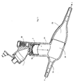
- Fig. 8 an alternative arrangement is illustrated.
- the axis of the inlet is above the axis at the outlet.
- This connector gives higher drug deposition results as a result of the gentle taper and increased internal volume. Rain-out is reduced due to the taper and increased internal volume.
- This device is used in conjunction with an insufflator to deliver aerosolised medication to the pneumoperitoneum along narrow bore tubing.
- the device is designed to address the widespread complications associated with minimally invasive surgery, and will create a greater distribution of medication on the organs to alleviate postoperative pain, adhesion formation and infection.
- Sterile water may be used.
- any suitable solution may be used. Solutions with a salt concentration in the range 1 ⁇ M (micro molar) to 154mM (milli molar) (0.9% saline) are optimum as they cover the majority of medical applications.
- saline concentrations can be readily nebulised using the aerosolisation technology used in the invention.
- Liquid, saline or water for humidifying purposes only and/or medicament can be delivered into the nebulizer reservoir through the opening in the top of the nebulizer that is appropriately sized to receive standard nebules or alternatively may be applied by syringe or other delivery means.
- the nebulizer can also act to deliver any agent presented in an liquid drug solution.
- the system facilitates delivery of, for example, pain-relief medications, anti-infectives, anti-inflammatory and/or chemotherapy agents in aerosol form to the body cavity. These therapeutic agents could also act as humidifying substances in their own right.
- the nebulised liquid entrained in the insufflation gas may contain any desired therapeutic and/or prophylactic agent.
- an agent may for example be one or more of an analgesic, an anti-inflammatory, an anaesthetic, an anti-infective such as an antibiotic, an anti-cancer chemotherapy agent, and/or any agent which interferes with processes that result in the adhesion function.
- Typical local anaesthetics are, for example, Ropivacaine, Bupivacaine and Lidocaine.
- Typical anti-infectives include antibiotics such as an aminoglycoside, a tetracycline, a fluroquinolone; anti-microbials such as a cephalosporin; and antifungals.
- Anti-inflammatories may be of the steroidal or non-steroidal type.
- Anti-cancer chemotherapy agents may be alkylating agents, antimetabolites anthracyclines, plant alkaloids, topoisomerase inhibitors, nitrosoureas, mitotic inhibitors, monoclonal antibodies, tyrosine kinase inhibitors, hormone therapies including corticosteroids, cancer vaccines, anti-estrogens, aromatase inhibitors, anti-androgens, anti-angiogenic agents and other antitumour agents.
- the agent which interferes with the adhesion function may be any of those outlined in WO2005/092264A , the entire contents of which are herein incorporated by reference.
- the agent may be a crystalloid, hyaluronic acid, surfactant, phospholipid, polyethyleneglycol, Tranilast (N-(3 1 ,4 1 -dimethoxycinnamoyl) anthranilic acid) or a Neurokinin 1 receptor (NK-1R) agonist, such as Aprepitant.
- Typical analgesics include aspirin, acetaminophen, ibuprofen, naproxen, a Cox-2 inhibitor such as celecoxib, morphine, oxycodone and hydrocodone.
- the system of the invention can be used for precise controlled delivery of drug and/or humidity during insufflation. No heating is required. Consequently there is no risk of damage to drugs due to heating.
- the system may be used to provide precise control over aerosol output can be exercised by utilising pulse rate control.
- the system may be used for targeted delivery of a range of drugs, thereby reducing systemic side effects.
- the system provides alleviation of post-surgical pain experienced by the patient.
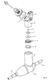
- the nebuliser (or aerosol generator), has a vibratable member which is vibrated at ultrasonic frequencies to produce liquid droplets.
- Some specific, non-limiting examples of technologies for producing fine liquid droplets is by supplying liquid to an aperture plate having a plurality of tapered apertures extending between a first surface and a second surface thereof and vibrating the aperture plate to eject liquid droplets through the apertures.
- Such technologies are described generally in U.S. Pat. Nos. 5,164,740 ; 5,938,117 ; 5,586,550 ; 5,758,637 ; 6,014,970, 6,085,740 , and US2005/021766A , the complete disclosures of which are incorporated herein by reference. However, it should be appreciated that the present invention is not limited for use only with such devices.
- the liquid to be aerosolised is received at the first surface, and the aerosol generator 2 generates the aerosolised first fluid at the second surface by ejecting droplets of the first fluid upon vibration of the vibratable member.
- the apertures in the vibratable member are sized to aerosolise the liquid by ejecting droplets of the liquid such that the majority of the droplets by mass have a size of less than 5 micrometers.
- the vibratable member 40 could be non-planar, and may be dome-shaped in geometry.
- the aerosol generator 2 comprises a vibratable member 40, a piezoelectric element 41 and a washer 42, which are sealed within a silicone overmould 43 or by using O rings and secured in place within the housing 36 using a retaining ring 44.
- the vibratable member 40 has a plurality of tapered apertures extending between a first surface and a second surface thereof.
- the first surface of the vibratable member 40 which in use faces upwardly, receives the liquid medicament from the reservoir 1 and the aerosolised medicament, is generated at the second surface of the vibratable member 40 by ejecting droplets of medicament upon vibration of the member 40. In use the second surface faces downwardly.
- the apertures in the vibratable member 40 may be sized to produce an aerosol in which the majority of the droplets by weight have a size of less than 5 micrometers.
- the complete nebuliser may be supplied in sterile form, which is a significant advantage for a surgical device.
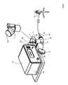
- liquid solution is fed from a reservoir 9 to the aerosol generator 2 along a delivery tube 13.
- a flow rate sensor/meter 11 is located in the flow path of the insufflation gas from an insufflator 12 to the aerosol generator 2.
- the flow rate sensor/meter 11 is connected by a control wire 70 to the controller 3, and the aerosol generator 2 is connected to the controller 3 by a control wire 16.
- the flow rate sensor/meter 11 may be a hot wire anemometer, or in the case where the flow is laminar or can be laminarised, a differential pressure transducer.
- Liquid solution may be stored in the reservoir I container of the nebuliser or the liquid solution may be delivered to the reservoir 1 of the aerosol generator 2 in this case from the supply reservoir 9 along the delivery line 13.
- the flow of liquid solution may be by gravity and/or may be assisted by an in-line flow controlling device 17 such as a pump and/or a valve which may be positioned in the delivery line 13.
- the operation of the flow controlling device 17 may be controlled by the controller 3 along a control wire 18 to ensure that the aerosol generator 2 has a supply of liquid solution during operation.
- the device 17 may be of any suitable type.
- the controller 3 controls operation of and provides a power supply to the aerosol generator 2.
- the aerosol generator has a housing which defines the reservoir 1.
- the housing has a signal interface port 38 fixed to the lower portion of the reservoir 1 to receive a control signal from the controller 3.
- the controller 3 may be connected to the signal interface port 38 by means of a control lead 39 which has a docking member 50 for mating with the port 38.
- a control signal and power may be passed from the controller 3 through the lead 39 and the port 38 to the aerosol generator 2 to control the operation of the aerosol generator 2 and to supply power to the aerosol generator 2 respectively.
- the power source for the controller 3 may be an on-board power source, such as a rechargeable battery, or a remote power source, such as a mains power source, or an insufflator power source.
- a remote power source such as a mains power source, or an insufflator power source.
- an AC-DC converter may be connected between the AC power source and the controller 3.
- a power connection lead may be provided to connect a power socket of the controller 3 with the remote power source.
- the controller 3 has a housing and a user interface to selectively control operation of the aerosol generator 2.
- the user interface is provided on the housing which, in use, is located remote from the aerosol generator housing.
- the user interface may be in the form of, for example, an on-off button.
- a button can be used to select pre-set values for simplicity of use.
- a dial mechanism can be used to select from a range of values from 0-100%.
- Status indication means are also provided on the housing to indicate the operational state of the aerosol generator 2.
- the status indication means may be in the form of two visible LED's, with one LED being used to indicate power and the other LED being used to indicate aerosol delivery.
- one LED may be used to indicate an operational state of the aerosol generator 2, and the other LED may be used to indicate a rest state of the aerosol generator. 2.
- a fault indicator may also be provided in the form of an LED on the housing.
- a battery charge indicator in the form of an LED may be provided at the side of the housing.
- the liquid solution in the reservoir flows by gravitational action towards the aerosol generator 2 at the lower medicament outlet.
- the controller 3 may then be activated to supply power and a control signal to the aerosol generator 2, which causes the piezoelectric element 41 to vibrate the non-planar member 40.
- This vibration of the non-planar member 40 causes the liquid solution at the top surface of the member 40 to pass through the apertures to the lower surface where the liquid solution is aerosolised by the ejection of small droplets of solution.
- the aerosol passes from the aerosol generator 2 into the neck 36 of the aerosol generator housing, which is mounted within the aerosol supply conduit of the connector 30 and into the gas conduit of the connector 30 (flow A).
- the aerosol is entrained in the insufflation gas conduit with gas, which passes into the gas conduit through the inlet 31 (flow B).
- the entrained mixture of the aerosol and the insufflation gas then passes out of the gas conduit through the outlet 32 (flow C) and on via an insufflator line 15 to a patient, for example into the abdomen of the patient.
- the flow of the insufflation gas into the abdomen of a patient is commenced to insufflate the abdomen.
- the flow rate sensor/meter 11 determines the flow rate of the insufflation gas.
- the controller 3 commences operation of the aerosol generator 2 to aerosolise the liquid solution.
- the aerosolised liquid solution is entrained with the insufflation gas, and delivered into the abdomen of the patient to insufflate at least part of the abdomen.
- the flow rate sensor/meter 11 determines the alteration, and the controller 3 alters the pulse rate of the vibratable member of the nebuliser accordingly.
- the controller 3 is in communication with the flow rate sensor/meter 11.
- the controller 3 is configured to control operation of the aerosol generator 2, responsive to the fluid flow rate of the insufflation gas and also independent of the fluid flow rate of the insufflation gas as required.
- the controller 3 is configured to control operation of the aerosol generator 2 by controlling the pulse rate at a set frequency of vibration of the vibratable member, and thus controlling the fluid flow rate of the liquid solutions.
- the controller 3 may comprise a microprocessor 4, a boost circuit 7, and a drive circuit 8.
- Fig. 2 illustrates the microprocessor 4, the boost circuit 7, the drive circuit 8 comprising impedance matching components (inductor), the nebuliser 2, and the aerosol.
- the inductor impedance is matched to the impedance of the piezoelectric element of the aerosol generator 2.
- the microprocessor 4 generates a square waveform of 128KHz which is sent to the drive circuit 8.
- the boost circuit 7 generates a 12V DC voltage required by the drive circuit 6 from an input of either a 4.5V battery or a 9V AC/DC adapter.
- the circuit is matched to the impedance of the piezo ceramic element to ensure enhanced energy transfer.
- a drive frequency of 128 KHz is generated to drive the nebuliser at close to its resonant frequency so that enough amplitude is generated to break off droplets and produce the aerosol. If this frequency is chopped at a lower frequency such that aerosol is generated for a short time and then stopped for a short time this gives good control of the nebuliser's flow rate. This lower frequency is called the pulse rate.
- the drive frequency may be started and stopped as required using the microprocessor 4. This allows for control of flow rate by driving the nebuliser 2 for any required pulse rate.
- the microprocessor 4 may control the on and off times to an accuracy of milliseconds.
- the nebuliser drive circuit consists of the electronic components designed to generate output sine waveform of approximately 100V AC which is fed to nebuliser 2 causing aerosol to be generated.
- the nebuliser drive circuit 6 uses inputs from microprocessor 4 and boost circuit 7 to achieve its output.
- the circuit is matched to the impedance of the piezo ceramic element to ensure good energy transfer.
- the aerosol generator 2 may be configured to operate in a variety of different modes, such as continuous, and/or phasic, and/or optimised.
- Fig 13(a) illustrates a 5V DC square waveform output from the microprocessor 4 to the drive circuit 6.
- Fig 7(b) shows a low power, ⁇ 100V AC sine waveform output from drive circuit 8 to nebuliser 2. Both waveforms have a period p of 7.8 ⁇ S giving them a frequency of 1/7.8 ⁇ s which is approximately 128KHz. Both waveforms are continuous without any pulsing.
- the aerosol generator may be operated in this mode to achieve 100% aerosol output.
- Figs 14(a) in another example, there is illustrated a 5V DC square waveform output from the microprocessor 4 to the drive circuit 8.
- Fig 14(b) shows a low power, ⁇ 100V AC sine waveform output from the drive circuit 6 to the nebuliser 2. Both waveforms have a period p of 7.8 ⁇ S giving them a frequency of 1/7.8 ⁇ s which is approximately 128KHz. In both cases the wavefoms are chopped (stopped/OFF) for a period of time x. In this case the off time x is equal to the on time x.
- the aerosol generator may be operated in this mode to achieve 50% aerosol output.
- Figs 15(a) there is illustrated a 5V DC square waveform output from microprocessor 4 to drive circuit 8.
- Fig 15(b) shows a low power, ⁇ 100V AC sine waveform output from the drive circuit 8 to the nebuliser 2.
- Both waveforms have a period p of 7.8 ⁇ S giving them a frequency of 1/7.8 ⁇ s which is approximately 128KHz.
- the wavefoms are chopped (stopped/OFF) for a period of time x. In this case the off time is 3x while the on time is x.
- the aerosol generator may be operated in this mode to achieve 25% aerosol output.
- pulsing is achieved by specifying an on-time and off-time for the vibration of the aperture plate. If the on-time is set to 200 vibrations and off-time is set to 200 vibrations, the pulse rate is 50% (1 ⁇ 2 on 1 ⁇ 2 off). This means that the flow rate is half of that of a fully driven aperture plate. Any number of vibrations can be specified but to achieve a linear relationship between flow rate and pulse rate a minimum number of on-time vibrations is specified since it takes a finite amount of time for the aperture plate to reach its maximum amplitude of vibrations.
- the drive frequency can be started and stopped as required by the microprocessor; this allows control of flow rate by driving the nebuliser for any required pulse rate.
- the microprocessor can control the on and off times with an accuracy of microseconds.
- a nebuliser can be calibrated at a certain pulse rate by measuring how long it takes to deliver a known quantity of solution. There is a linear relationship between the pulse rate and that nebuliser's flow rate. This allows accurate control of the rate of delivery of the aerosolised liquid solution.
- the ability to calibrate each nebulizer ensures that any inherent variation in output rate between each nebulizer can be eliminated.
- the output from each nebulizer when in-line in the insufflator circuit will be equivalent to a second nebulizer although the inherent flow rates of the two nebulizers are different.
- the first nebulizer is controlled with a 50:50 on:off pulse rate, with the second set to a 25:75 on-off pulse rate so that both nebulizers give a 0.044ml/min output.
- This feature ensures that the nebulizers when located in the insufflation circuit have the potential to provide exactly the same rate of aerosol output as each other. This is possible because the amount of humidity a gas can hold is a known constant dependent on controllable factors.
- the pulse rate may be lowered so that the velocity of the emerging aerosol is much reduced so that impaction rain-out is reduced.
- Detection of when the aperture plate is dry can be achieved by using the fact that a dry aperture plate has a well defined resonant frequency. If the drive frequency is swept from 120kHz to 145kHz and the current is measured then if a minimum current is detected less than a set value, the aperture plate must have gone dry. A wet aperture plate has no resonant frequency.
- the apparatus of the invention may be configured to determine whether there is any of the first fluid in contact with the aerosol generator 2. By determining an electrical characteristic of the aerosol generator 2, for example the current flowing through the aerosol generator 2, over a range of vibration frequencies, and comparing this electrical characteristic against a pre-defined set of data, it is possible to determine whether the aerosol generator 2 has any solution in contact with the aerosol generator 2. Fig.
- FIG. 17 illustrates a curve 80 of frequency versus current when there is some of the solution in contact with the aerosol generator 2, and illustrates a curve 90 of frequency versus current when there is none of the solution in contact with the aerosol generator 2.
- Fig. 17 illustrates the wet aperture plate curve 80 and the dry aperture plate curve 90.
- a pump can be added in line to give fine control of the liquid delivery rate which can be nebulised drip by drip.
- the rate would be set so that liquid would not build up in the nebuliser.
- This system is particularly suitable for constant low dose delivery.
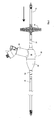
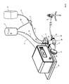
- Fig. 18 there is illustrated another insufflation apparatus which is similar to the apparatus of Fig. 1 and like parts are arranged the same reference numerals.
- the controller 3 is integrated into the insufflator 12.
- the insufflator 12 would have information on the rate of flow that it is producing and using an integrated circuit board may directly communicate with the nebuliser 2. This would eliminate the need for the separate flowmeter 11 and the stand-alone controller 3 to be present.
- insufflator 12 there may be a common information bus between the insufflator 12 and the controller 3.
- the insufflator 12 would have information on the rate of flow that it is producing and would communicate this to the controller 3 and on to the nebuliser 2, thereby eliminating the need for the flowmeter 11. This would allow the invention to be backward compatible with a variety of types of insufflator.
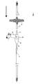
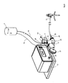
- FIG. 19 there is illustrated another insufflation apparatus which is similar to the apparatus of Fig. 1 and like parts are again identified by the same reference numerals.
- the insufflation gas flow signal is provided directly from the insufflator along a lead 71.
- One advantage of this arrangement is that no separate meter/sensor required.
- nebuliser reservoir 1 has a top opening 100 which is closable by removable plug 101.
- Liquid, saline or water for humidifying purposes and/or medicament is delivered into the nebuliser reservoir through the opening 100.
- the opening 100 is appropriately sized to receive standard nebules containing liquid to be nebulised.
- the liquid may be applied by syringe or other suitable delivery means.
- nebuliser 1 pre-loaded with medicament to avoid the requirement to separately add medicament to the system.
- Fig. 20 The apparatus of Fig. 20 is operated in a similar way to the modes of operation described above with reference to Figs. 2 to 11 .
- nebuliser reservoir 1 has a top opening 100 and a removable plug/lid 101 as described with reference to Fig. 14 and the apparatus is operated as described above with the liquid being introduced through the opening 100.
- the nebuliser may be pre-loaded with medicament.
- Fig. 22 there is illustrated another apparatus of the invention which is similar to that described above with reference to Fig. 13 and like parts are assigned the same reference numerals.
- the nebuliser reservoir 1 again has a top opening 100 and a removable lid 101 as described with reference to Fig. 20 and the apparatus is operated as described above with the liquid being introduced through the opening 100.
- the nebuliser may be pre-loaded with medicament.
- the apparatus is operated as described above.
- Fig. 23 shows the connection of the controller lead 71 to the control circuit 105 of the insufflator 12.
- nebuliser reservoir 1 is closed by a lid 110 and the nebuliser is pre-loaded with medicament/liquid which avoids the requirement to separately add medicament to the system.
- Humidity may be generated via the aerosolisation of any liquid solution. Relative humidity in the 50-100% range would be optimum.
- the control module can generate a nebuliser output of any defined relative humidity percentage based on the insufflator flow. These solutions include any liquid drug solution. Solutions with salt concentrations in the range 1 ⁇ M ⁇ 154mM would be optimum.
- nebulizer to humidify the insufflation gas prior to entering the body will eliminate the need for the body to humidify the gas once it is inside the body, thereby minimizing body heat loss by internal evaporation.
- control in nebulizer output allows proportional delivery of the required amount of humidity according to the amount of insufflation gas entering the body.
- this control of aerosolization rate will prevent overloading of the insufflation gas with aerosol which would obscure the surgeons view.
- the invention provides a system that can deliver different flow rates at different stages of the surgical procedure. Examples of such different flow rates include:
- the controller which controls the operation of the aerosol generator is pre-set to deliver a set amount of aerosol into the insufflation gas.
- the controller may be set to deliver an amount of 5% into a flow of 1 litre per minute of insufflation gas to avoid fogging.
- the controller may be pre-set in the factory to operate in this manner.
- there may be a user interface such as a switch, or keypad which may be used to change the setting. In these arrangements control responsive to an insufflation gas flow sensor is not essential.
- nebuliser may not have finished delivering the first therapeutic chosen by the time the second therapeutic is required.
- the nebuliser may not have finished delivering the first therapeutic chosen by the time the second therapeutic is required.
- the nebuliser may not have finished delivering the first therapeutic chosen by the time the second therapeutic is required.
- the nebuliser may not have finished delivering the first therapeutic chosen by the time the second therapeutic is required.
- the therapeutics chosen there may be issues resulting from mixing the two within the nebuliser reservoir while in liquid form creating difficulties in delivering both simultaneously or in series. This problem may be overcome by incorporating a second nebuliser into the circuit.
- the system need not be located in the direct flow path of insufflation gas. In addition, minimal caregiver intervention during laparoscopic procedure is required.
- the system is small and compact and allows for integration with an insufflator.
- the device of the invention can be used throughout the procedure carried out by a surgeon.
- the device ensures that humidity is actively controlled during the procedure and thus ensures that a surgeon's view is clear as fogging is avoided.
- the nebuliser output is controlled by pulsing to provide delivery of humidity and/or medicament into the insufflation gas during surgery without causing fogging.
- the control may be provided either by providing a maximum output limit on the nebuliser or by linking directly to the insufflator flow.
Landscapes
- Health & Medical Sciences (AREA)
- Engineering & Computer Science (AREA)
- Anesthesiology (AREA)
- Biomedical Technology (AREA)
- Heart & Thoracic Surgery (AREA)
- Hematology (AREA)
- Life Sciences & Earth Sciences (AREA)
- Animal Behavior & Ethology (AREA)
- General Health & Medical Sciences (AREA)
- Public Health (AREA)
- Veterinary Medicine (AREA)
- Emergency Medicine (AREA)
- Pulmonology (AREA)
- Surgical Instruments (AREA)
Priority Applications (1)
| Application Number | Priority Date | Filing Date | Title |
|---|---|---|---|
| EP10394006A EP2371409A1 (fr) | 2010-03-31 | 2010-03-31 | Insufflation de cavités corporelles |
Applications Claiming Priority (1)
| Application Number | Priority Date | Filing Date | Title |
|---|---|---|---|
| EP10394006A EP2371409A1 (fr) | 2010-03-31 | 2010-03-31 | Insufflation de cavités corporelles |
Publications (1)
| Publication Number | Publication Date |
|---|---|
| EP2371409A1 true EP2371409A1 (fr) | 2011-10-05 |
Family
ID=42338292
Family Applications (1)
| Application Number | Title | Priority Date | Filing Date |
|---|---|---|---|
| EP10394006A Withdrawn EP2371409A1 (fr) | 2010-03-31 | 2010-03-31 | Insufflation de cavités corporelles |
Country Status (1)
| Country | Link |
|---|---|
| EP (1) | EP2371409A1 (fr) |
Cited By (5)
| Publication number | Priority date | Publication date | Assignee | Title |
|---|---|---|---|---|
| WO2015167347A1 (fr) * | 2014-05-02 | 2015-11-05 | Fisher & Paykel Healthcare Limited | Dispositif d'humidification de gaz |
| CN108717010A (zh) * | 2018-07-12 | 2018-10-30 | 清华大学深圳研究生院 | 一种用于产生和筛选雾化气溶胶的装置 |
| EP3636305A4 (fr) * | 2018-05-11 | 2020-07-08 | Taian Dalu Medical Instrument Co., Ltd. | Nébuliseur médical |
| EP4059550A4 (fr) * | 2019-11-12 | 2023-11-29 | Bhio Supply Indústria e Comércio de Equipamentos Médicos Ltda. | Plateforme d'aérosolisation par ultrasons pour l'application de substances thérapeutiques dans des cavités corporelles |
| WO2024039805A1 (fr) * | 2022-08-18 | 2024-02-22 | Conmed Corporation | Systèmes d'humidification pour procédures chirurgicales |
Citations (14)
| Publication number | Priority date | Publication date | Assignee | Title |
|---|---|---|---|---|
| US5164740A (en) | 1991-04-24 | 1992-11-17 | Yehuda Ivri | High frequency printing mechanism |
| EP0682955A1 (fr) * | 1994-05-19 | 1995-11-22 | PAUL RITZAU PARI-WERK GmbH | Dispositif pour sécher et amortir l'écoulement d'aérosols |
| US5586550A (en) | 1995-08-31 | 1996-12-24 | Fluid Propulsion Technologies, Inc. | Apparatus and methods for the delivery of therapeutic liquids to the respiratory system |
| US5758637A (en) | 1995-08-31 | 1998-06-02 | Aerogen, Inc. | Liquid dispensing apparatus and methods |
| US5938117A (en) | 1991-04-24 | 1999-08-17 | Aerogen, Inc. | Methods and apparatus for dispensing liquids as an atomized spray |
| US6014970A (en) | 1998-06-11 | 2000-01-18 | Aerogen, Inc. | Methods and apparatus for storing chemical compounds in a portable inhaler |
| US6085740A (en) | 1996-02-21 | 2000-07-11 | Aerogen, Inc. | Liquid dispensing apparatus and methods |
| US6540154B1 (en) | 1991-04-24 | 2003-04-01 | Aerogen, Inc. | Systems and methods for controlling fluid feed to an aerosol generator |
| US6546927B2 (en) | 2001-03-13 | 2003-04-15 | Aerogen, Inc. | Methods and apparatus for controlling piezoelectric vibration |
| WO2004101040A1 (fr) * | 2003-05-16 | 2004-11-25 | University Of Alberta | Concept pour dispositif d'espacement supplementaire pour des inhalateurs de poudre seche |
| US6845770B2 (en) | 2002-01-15 | 2005-01-25 | Aerogen, Inc. | Systems and methods for clearing aerosols from the effective anatomic dead space |
| US20050021766A1 (en) | 2001-03-26 | 2005-01-27 | Mckeowen Jean Christophe | Broadband communications |
| WO2005092264A1 (fr) | 2004-03-10 | 2005-10-06 | Ethicon, Inc. | Prevention des adherences amelioree par des medicaments |
| WO2009118717A1 (fr) * | 2008-03-28 | 2009-10-01 | Stamford Devices Limited | Insufflation de cavités corporelles |
-
2010
- 2010-03-31 EP EP10394006A patent/EP2371409A1/fr not_active Withdrawn
Patent Citations (14)
| Publication number | Priority date | Publication date | Assignee | Title |
|---|---|---|---|---|
| US5164740A (en) | 1991-04-24 | 1992-11-17 | Yehuda Ivri | High frequency printing mechanism |
| US5938117A (en) | 1991-04-24 | 1999-08-17 | Aerogen, Inc. | Methods and apparatus for dispensing liquids as an atomized spray |
| US6540154B1 (en) | 1991-04-24 | 2003-04-01 | Aerogen, Inc. | Systems and methods for controlling fluid feed to an aerosol generator |
| EP0682955A1 (fr) * | 1994-05-19 | 1995-11-22 | PAUL RITZAU PARI-WERK GmbH | Dispositif pour sécher et amortir l'écoulement d'aérosols |
| US5586550A (en) | 1995-08-31 | 1996-12-24 | Fluid Propulsion Technologies, Inc. | Apparatus and methods for the delivery of therapeutic liquids to the respiratory system |
| US5758637A (en) | 1995-08-31 | 1998-06-02 | Aerogen, Inc. | Liquid dispensing apparatus and methods |
| US6085740A (en) | 1996-02-21 | 2000-07-11 | Aerogen, Inc. | Liquid dispensing apparatus and methods |
| US6014970A (en) | 1998-06-11 | 2000-01-18 | Aerogen, Inc. | Methods and apparatus for storing chemical compounds in a portable inhaler |
| US6546927B2 (en) | 2001-03-13 | 2003-04-15 | Aerogen, Inc. | Methods and apparatus for controlling piezoelectric vibration |
| US20050021766A1 (en) | 2001-03-26 | 2005-01-27 | Mckeowen Jean Christophe | Broadband communications |
| US6845770B2 (en) | 2002-01-15 | 2005-01-25 | Aerogen, Inc. | Systems and methods for clearing aerosols from the effective anatomic dead space |
| WO2004101040A1 (fr) * | 2003-05-16 | 2004-11-25 | University Of Alberta | Concept pour dispositif d'espacement supplementaire pour des inhalateurs de poudre seche |
| WO2005092264A1 (fr) | 2004-03-10 | 2005-10-06 | Ethicon, Inc. | Prevention des adherences amelioree par des medicaments |
| WO2009118717A1 (fr) * | 2008-03-28 | 2009-10-01 | Stamford Devices Limited | Insufflation de cavités corporelles |
Cited By (8)
| Publication number | Priority date | Publication date | Assignee | Title |
|---|---|---|---|---|
| WO2015167347A1 (fr) * | 2014-05-02 | 2015-11-05 | Fisher & Paykel Healthcare Limited | Dispositif d'humidification de gaz |
| US11173272B2 (en) | 2014-05-02 | 2021-11-16 | Fisher & Paykel Healthcare Limited | Gas humidification arrangement |
| US12515009B2 (en) | 2014-05-02 | 2026-01-06 | Fisher & Paykel Healthcare Limited | Gas humidification arrangement |
| EP3636305A4 (fr) * | 2018-05-11 | 2020-07-08 | Taian Dalu Medical Instrument Co., Ltd. | Nébuliseur médical |
| CN108717010A (zh) * | 2018-07-12 | 2018-10-30 | 清华大学深圳研究生院 | 一种用于产生和筛选雾化气溶胶的装置 |
| CN108717010B (zh) * | 2018-07-12 | 2020-09-22 | 清华大学深圳研究生院 | 一种用于产生和筛选雾化气溶胶的装置 |
| EP4059550A4 (fr) * | 2019-11-12 | 2023-11-29 | Bhio Supply Indústria e Comércio de Equipamentos Médicos Ltda. | Plateforme d'aérosolisation par ultrasons pour l'application de substances thérapeutiques dans des cavités corporelles |
| WO2024039805A1 (fr) * | 2022-08-18 | 2024-02-22 | Conmed Corporation | Systèmes d'humidification pour procédures chirurgicales |
Similar Documents
| Publication | Publication Date | Title |
|---|---|---|
| US11738159B2 (en) | Insufflation system | |
| US20110230820A1 (en) | Insufflation of body cavities | |
| EP2464403B1 (fr) | Système d'insufflation | |
| US20110178458A1 (en) | Insufflation of body cavities | |
| US20090240192A1 (en) | Insufflation of body cavities | |
| US11806478B2 (en) | Supplemental oxygen delivery system | |
| US20120234321A1 (en) | Aerosolisation system | |
| US20130255670A1 (en) | System and Method for Performing a Surgical Procedure | |
| EP2371409A1 (fr) | Insufflation de cavités corporelles | |
| EP2274034A1 (fr) | Insufflation de cavités corporelles | |
| IE20100498A1 (en) | An insufflation system | |
| IE20080238A1 (en) | Insufflation of body cavities | |
| IE20090237A1 (en) | Insufflation of body cavities | |
| EP2388041A1 (fr) | Appareil de distribution d'un agent dans l'abdomen | |
| EP2457611A2 (fr) | Methode et appareil permettant de delivrer un agent dans l'abdomen | |
| IE20090749A1 (en) | A supplemental oxygen delivery system | |
| EP1809366A1 (fr) | Procede et appareil d'administration d'un agent dans l'abdomen | |
| WO2006041476A1 (fr) | Procede et appareil d'administration d'un agent dans l'abdomen |
Legal Events
| Date | Code | Title | Description |
|---|---|---|---|
| PUAI | Public reference made under article 153(3) epc to a published international application that has entered the european phase |
Free format text: ORIGINAL CODE: 0009012 |
|
| AK | Designated contracting states |
Kind code of ref document: A1 Designated state(s): AT BE BG CH CY CZ DE DK EE ES FI FR GB GR HR HU IE IS IT LI LT LU LV MC MK MT NL NO PL PT RO SE SI SK SM TR |
|
| AX | Request for extension of the european patent |
Extension state: AL BA ME RS |
|
| STAA | Information on the status of an ep patent application or granted ep patent |
Free format text: STATUS: THE APPLICATION IS DEEMED TO BE WITHDRAWN |
|
| 18D | Application deemed to be withdrawn |
Effective date: 20120406 |