EP2371521B1 - Procédé de fabrication d'un redresseur - Google Patents
Procédé de fabrication d'un redresseur Download PDFInfo
- Publication number
- EP2371521B1 EP2371521B1 EP10159064.4A EP10159064A EP2371521B1 EP 2371521 B1 EP2371521 B1 EP 2371521B1 EP 10159064 A EP10159064 A EP 10159064A EP 2371521 B1 EP2371521 B1 EP 2371521B1
- Authority
- EP
- European Patent Office
- Prior art keywords
- disc
- vane
- resin
- preform
- reinforcement
- Prior art date
- Legal status (The legal status is an assumption and is not a legal conclusion. Google has not performed a legal analysis and makes no representation as to the accuracy of the status listed.)
- Active
Links
Images


Classifications
-
- B—PERFORMING OPERATIONS; TRANSPORTING
- B29—WORKING OF PLASTICS; WORKING OF SUBSTANCES IN A PLASTIC STATE IN GENERAL
- B29C—SHAPING OR JOINING OF PLASTICS; SHAPING OF MATERIAL IN A PLASTIC STATE, NOT OTHERWISE PROVIDED FOR; AFTER-TREATMENT OF THE SHAPED PRODUCTS, e.g. REPAIRING
- B29C70/00—Shaping composites, i.e. plastics material comprising reinforcements, fillers or preformed parts, e.g. inserts
- B29C70/04—Shaping composites, i.e. plastics material comprising reinforcements, fillers or preformed parts, e.g. inserts comprising reinforcements only, e.g. self-reinforcing plastics
- B29C70/28—Shaping operations therefor
- B29C70/40—Shaping or impregnating by compression not applied
- B29C70/42—Shaping or impregnating by compression not applied for producing articles of definite length, i.e. discrete articles
- B29C70/46—Shaping or impregnating by compression not applied for producing articles of definite length, i.e. discrete articles using matched moulds, e.g. for deforming sheet moulding compounds [SMC] or prepregs
- B29C70/48—Shaping or impregnating by compression not applied for producing articles of definite length, i.e. discrete articles using matched moulds, e.g. for deforming sheet moulding compounds [SMC] or prepregs and impregnating the reinforcements in the closed mould, e.g. resin transfer moulding [RTM], e.g. by vacuum
-
- B—PERFORMING OPERATIONS; TRANSPORTING
- B29—WORKING OF PLASTICS; WORKING OF SUBSTANCES IN A PLASTIC STATE IN GENERAL
- B29C—SHAPING OR JOINING OF PLASTICS; SHAPING OF MATERIAL IN A PLASTIC STATE, NOT OTHERWISE PROVIDED FOR; AFTER-TREATMENT OF THE SHAPED PRODUCTS, e.g. REPAIRING
- B29C53/00—Shaping by bending, folding, twisting, straightening or flattening; Apparatus therefor
- B29C53/56—Winding and joining, e.g. winding spirally
- B29C53/58—Winding and joining, e.g. winding spirally helically
- B29C53/583—Winding and joining, e.g. winding spirally helically for making tubular articles with particular features
- B29C53/587—Winding and joining, e.g. winding spirally helically for making tubular articles with particular features having a non-uniform wall-structure, e.g. with inserts, perforations, locally concentrated reinforcements
-
- B—PERFORMING OPERATIONS; TRANSPORTING
- B29—WORKING OF PLASTICS; WORKING OF SUBSTANCES IN A PLASTIC STATE IN GENERAL
- B29C—SHAPING OR JOINING OF PLASTICS; SHAPING OF MATERIAL IN A PLASTIC STATE, NOT OTHERWISE PROVIDED FOR; AFTER-TREATMENT OF THE SHAPED PRODUCTS, e.g. REPAIRING
- B29C70/00—Shaping composites, i.e. plastics material comprising reinforcements, fillers or preformed parts, e.g. inserts
- B29C70/04—Shaping composites, i.e. plastics material comprising reinforcements, fillers or preformed parts, e.g. inserts comprising reinforcements only, e.g. self-reinforcing plastics
- B29C70/28—Shaping operations therefor
- B29C70/30—Shaping by lay-up, i.e. applying fibres, tape or broadsheet on a mould, former or core; Shaping by spray-up, i.e. spraying of fibres on a mould, former or core
- B29C70/32—Shaping by lay-up, i.e. applying fibres, tape or broadsheet on a mould, former or core; Shaping by spray-up, i.e. spraying of fibres on a mould, former or core on a rotating mould, former or core
-
- B—PERFORMING OPERATIONS; TRANSPORTING
- B29—WORKING OF PLASTICS; WORKING OF SUBSTANCES IN A PLASTIC STATE IN GENERAL
- B29C—SHAPING OR JOINING OF PLASTICS; SHAPING OF MATERIAL IN A PLASTIC STATE, NOT OTHERWISE PROVIDED FOR; AFTER-TREATMENT OF THE SHAPED PRODUCTS, e.g. REPAIRING
- B29C70/00—Shaping composites, i.e. plastics material comprising reinforcements, fillers or preformed parts, e.g. inserts
- B29C70/68—Shaping composites, i.e. plastics material comprising reinforcements, fillers or preformed parts, e.g. inserts by incorporating or moulding on preformed parts, e.g. inserts or layers, e.g. foam blocks
- B29C70/86—Incorporated in coherent impregnated reinforcing layers, e.g. by winding
-
- B—PERFORMING OPERATIONS; TRANSPORTING
- B29—WORKING OF PLASTICS; WORKING OF SUBSTANCES IN A PLASTIC STATE IN GENERAL
- B29C—SHAPING OR JOINING OF PLASTICS; SHAPING OF MATERIAL IN A PLASTIC STATE, NOT OTHERWISE PROVIDED FOR; AFTER-TREATMENT OF THE SHAPED PRODUCTS, e.g. REPAIRING
- B29C70/00—Shaping composites, i.e. plastics material comprising reinforcements, fillers or preformed parts, e.g. inserts
- B29C70/68—Shaping composites, i.e. plastics material comprising reinforcements, fillers or preformed parts, e.g. inserts by incorporating or moulding on preformed parts, e.g. inserts or layers, e.g. foam blocks
- B29C70/86—Incorporated in coherent impregnated reinforcing layers, e.g. by winding
- B29C70/865—Incorporated in coherent impregnated reinforcing layers, e.g. by winding completely encapsulated
-
- F—MECHANICAL ENGINEERING; LIGHTING; HEATING; WEAPONS; BLASTING
- F01—MACHINES OR ENGINES IN GENERAL; ENGINE PLANTS IN GENERAL; STEAM ENGINES
- F01D—NON-POSITIVE DISPLACEMENT MACHINES OR ENGINES, e.g. STEAM TURBINES
- F01D9/00—Stators
- F01D9/02—Nozzles; Nozzle boxes; Stator blades; Guide conduits, e.g. individual nozzles
- F01D9/04—Nozzles; Nozzle boxes; Stator blades; Guide conduits, e.g. individual nozzles forming ring or sector
-
- F—MECHANICAL ENGINEERING; LIGHTING; HEATING; WEAPONS; BLASTING
- F01—MACHINES OR ENGINES IN GENERAL; ENGINE PLANTS IN GENERAL; STEAM ENGINES
- F01D—NON-POSITIVE DISPLACEMENT MACHINES OR ENGINES, e.g. STEAM TURBINES
- F01D9/00—Stators
- F01D9/02—Nozzles; Nozzle boxes; Stator blades; Guide conduits, e.g. individual nozzles
- F01D9/04—Nozzles; Nozzle boxes; Stator blades; Guide conduits, e.g. individual nozzles forming ring or sector
- F01D9/042—Nozzles; Nozzle boxes; Stator blades; Guide conduits, e.g. individual nozzles forming ring or sector fixing blades to stators
- F01D9/044—Nozzles; Nozzle boxes; Stator blades; Guide conduits, e.g. individual nozzles forming ring or sector fixing blades to stators permanently, e.g. by welding, brazing, casting or the like
-
- B—PERFORMING OPERATIONS; TRANSPORTING
- B29—WORKING OF PLASTICS; WORKING OF SUBSTANCES IN A PLASTIC STATE IN GENERAL
- B29C—SHAPING OR JOINING OF PLASTICS; SHAPING OF MATERIAL IN A PLASTIC STATE, NOT OTHERWISE PROVIDED FOR; AFTER-TREATMENT OF THE SHAPED PRODUCTS, e.g. REPAIRING
- B29C65/00—Joining or sealing of preformed parts, e.g. welding of plastics materials; Apparatus therefor
- B29C65/02—Joining or sealing of preformed parts, e.g. welding of plastics materials; Apparatus therefor by heating, with or without pressure
-
- B—PERFORMING OPERATIONS; TRANSPORTING
- B29—WORKING OF PLASTICS; WORKING OF SUBSTANCES IN A PLASTIC STATE IN GENERAL
- B29C—SHAPING OR JOINING OF PLASTICS; SHAPING OF MATERIAL IN A PLASTIC STATE, NOT OTHERWISE PROVIDED FOR; AFTER-TREATMENT OF THE SHAPED PRODUCTS, e.g. REPAIRING
- B29C66/00—General aspects of processes or apparatus for joining preformed parts
- B29C66/40—General aspects of joining substantially flat articles, e.g. plates, sheets or web-like materials; Making flat seams in tubular or hollow articles; Joining single elements to substantially flat surfaces
- B29C66/47—Joining single elements to sheets, plates or other substantially flat surfaces
- B29C66/474—Joining single elements to sheets, plates or other substantially flat surfaces said single elements being substantially non-flat
-
- B—PERFORMING OPERATIONS; TRANSPORTING
- B29—WORKING OF PLASTICS; WORKING OF SUBSTANCES IN A PLASTIC STATE IN GENERAL
- B29C—SHAPING OR JOINING OF PLASTICS; SHAPING OF MATERIAL IN A PLASTIC STATE, NOT OTHERWISE PROVIDED FOR; AFTER-TREATMENT OF THE SHAPED PRODUCTS, e.g. REPAIRING
- B29C66/00—General aspects of processes or apparatus for joining preformed parts
- B29C66/70—General aspects of processes or apparatus for joining preformed parts characterised by the composition, physical properties or the structure of the material of the parts to be joined; Joining with non-plastics material
- B29C66/72—General aspects of processes or apparatus for joining preformed parts characterised by the composition, physical properties or the structure of the material of the parts to be joined; Joining with non-plastics material characterised by the structure of the material of the parts to be joined
- B29C66/721—Fibre-reinforced materials
-
- B—PERFORMING OPERATIONS; TRANSPORTING
- B29—WORKING OF PLASTICS; WORKING OF SUBSTANCES IN A PLASTIC STATE IN GENERAL
- B29C—SHAPING OR JOINING OF PLASTICS; SHAPING OF MATERIAL IN A PLASTIC STATE, NOT OTHERWISE PROVIDED FOR; AFTER-TREATMENT OF THE SHAPED PRODUCTS, e.g. REPAIRING
- B29C66/00—General aspects of processes or apparatus for joining preformed parts
- B29C66/70—General aspects of processes or apparatus for joining preformed parts characterised by the composition, physical properties or the structure of the material of the parts to be joined; Joining with non-plastics material
- B29C66/72—General aspects of processes or apparatus for joining preformed parts characterised by the composition, physical properties or the structure of the material of the parts to be joined; Joining with non-plastics material characterised by the structure of the material of the parts to be joined
- B29C66/723—General aspects of processes or apparatus for joining preformed parts characterised by the composition, physical properties or the structure of the material of the parts to be joined; Joining with non-plastics material characterised by the structure of the material of the parts to be joined being multi-layered
-
- B—PERFORMING OPERATIONS; TRANSPORTING
- B29—WORKING OF PLASTICS; WORKING OF SUBSTANCES IN A PLASTIC STATE IN GENERAL
- B29C—SHAPING OR JOINING OF PLASTICS; SHAPING OF MATERIAL IN A PLASTIC STATE, NOT OTHERWISE PROVIDED FOR; AFTER-TREATMENT OF THE SHAPED PRODUCTS, e.g. REPAIRING
- B29C66/00—General aspects of processes or apparatus for joining preformed parts
- B29C66/70—General aspects of processes or apparatus for joining preformed parts characterised by the composition, physical properties or the structure of the material of the parts to be joined; Joining with non-plastics material
- B29C66/73—General aspects of processes or apparatus for joining preformed parts characterised by the composition, physical properties or the structure of the material of the parts to be joined; Joining with non-plastics material characterised by the intensive physical properties of the material of the parts to be joined, by the optical properties of the material of the parts to be joined, by the extensive physical properties of the parts to be joined, by the state of the material of the parts to be joined or by the material of the parts to be joined being a thermoplastic or a thermoset
- B29C66/737—General aspects of processes or apparatus for joining preformed parts characterised by the composition, physical properties or the structure of the material of the parts to be joined; Joining with non-plastics material characterised by the intensive physical properties of the material of the parts to be joined, by the optical properties of the material of the parts to be joined, by the extensive physical properties of the parts to be joined, by the state of the material of the parts to be joined or by the material of the parts to be joined being a thermoplastic or a thermoset characterised by the state of the material of the parts to be joined
- B29C66/7375—General aspects of processes or apparatus for joining preformed parts characterised by the composition, physical properties or the structure of the material of the parts to be joined; Joining with non-plastics material characterised by the intensive physical properties of the material of the parts to be joined, by the optical properties of the material of the parts to be joined, by the extensive physical properties of the parts to be joined, by the state of the material of the parts to be joined or by the material of the parts to be joined being a thermoplastic or a thermoset characterised by the state of the material of the parts to be joined uncured, partially cured or fully cured
- B29C66/73751—General aspects of processes or apparatus for joining preformed parts characterised by the composition, physical properties or the structure of the material of the parts to be joined; Joining with non-plastics material characterised by the intensive physical properties of the material of the parts to be joined, by the optical properties of the material of the parts to be joined, by the extensive physical properties of the parts to be joined, by the state of the material of the parts to be joined or by the material of the parts to be joined being a thermoplastic or a thermoset characterised by the state of the material of the parts to be joined uncured, partially cured or fully cured the to-be-joined area of at least one of the parts to be joined being uncured, i.e. non cross-linked, non vulcanized
-
- B—PERFORMING OPERATIONS; TRANSPORTING
- B29—WORKING OF PLASTICS; WORKING OF SUBSTANCES IN A PLASTIC STATE IN GENERAL
- B29C—SHAPING OR JOINING OF PLASTICS; SHAPING OF MATERIAL IN A PLASTIC STATE, NOT OTHERWISE PROVIDED FOR; AFTER-TREATMENT OF THE SHAPED PRODUCTS, e.g. REPAIRING
- B29C66/00—General aspects of processes or apparatus for joining preformed parts
- B29C66/70—General aspects of processes or apparatus for joining preformed parts characterised by the composition, physical properties or the structure of the material of the parts to be joined; Joining with non-plastics material
- B29C66/73—General aspects of processes or apparatus for joining preformed parts characterised by the composition, physical properties or the structure of the material of the parts to be joined; Joining with non-plastics material characterised by the intensive physical properties of the material of the parts to be joined, by the optical properties of the material of the parts to be joined, by the extensive physical properties of the parts to be joined, by the state of the material of the parts to be joined or by the material of the parts to be joined being a thermoplastic or a thermoset
- B29C66/739—General aspects of processes or apparatus for joining preformed parts characterised by the composition, physical properties or the structure of the material of the parts to be joined; Joining with non-plastics material characterised by the intensive physical properties of the material of the parts to be joined, by the optical properties of the material of the parts to be joined, by the extensive physical properties of the parts to be joined, by the state of the material of the parts to be joined or by the material of the parts to be joined being a thermoplastic or a thermoset characterised by the material of the parts to be joined being a thermoplastic or a thermoset
- B29C66/7392—General aspects of processes or apparatus for joining preformed parts characterised by the composition, physical properties or the structure of the material of the parts to be joined; Joining with non-plastics material characterised by the intensive physical properties of the material of the parts to be joined, by the optical properties of the material of the parts to be joined, by the extensive physical properties of the parts to be joined, by the state of the material of the parts to be joined or by the material of the parts to be joined being a thermoplastic or a thermoset characterised by the material of the parts to be joined being a thermoplastic or a thermoset characterised by the material of at least one of the parts being a thermoplastic
-
- B—PERFORMING OPERATIONS; TRANSPORTING
- B29—WORKING OF PLASTICS; WORKING OF SUBSTANCES IN A PLASTIC STATE IN GENERAL
- B29C—SHAPING OR JOINING OF PLASTICS; SHAPING OF MATERIAL IN A PLASTIC STATE, NOT OTHERWISE PROVIDED FOR; AFTER-TREATMENT OF THE SHAPED PRODUCTS, e.g. REPAIRING
- B29C66/00—General aspects of processes or apparatus for joining preformed parts
- B29C66/70—General aspects of processes or apparatus for joining preformed parts characterised by the composition, physical properties or the structure of the material of the parts to be joined; Joining with non-plastics material
- B29C66/73—General aspects of processes or apparatus for joining preformed parts characterised by the composition, physical properties or the structure of the material of the parts to be joined; Joining with non-plastics material characterised by the intensive physical properties of the material of the parts to be joined, by the optical properties of the material of the parts to be joined, by the extensive physical properties of the parts to be joined, by the state of the material of the parts to be joined or by the material of the parts to be joined being a thermoplastic or a thermoset
- B29C66/739—General aspects of processes or apparatus for joining preformed parts characterised by the composition, physical properties or the structure of the material of the parts to be joined; Joining with non-plastics material characterised by the intensive physical properties of the material of the parts to be joined, by the optical properties of the material of the parts to be joined, by the extensive physical properties of the parts to be joined, by the state of the material of the parts to be joined or by the material of the parts to be joined being a thermoplastic or a thermoset characterised by the material of the parts to be joined being a thermoplastic or a thermoset
- B29C66/7394—General aspects of processes or apparatus for joining preformed parts characterised by the composition, physical properties or the structure of the material of the parts to be joined; Joining with non-plastics material characterised by the intensive physical properties of the material of the parts to be joined, by the optical properties of the material of the parts to be joined, by the extensive physical properties of the parts to be joined, by the state of the material of the parts to be joined or by the material of the parts to be joined being a thermoplastic or a thermoset characterised by the material of the parts to be joined being a thermoplastic or a thermoset characterised by the material of at least one of the parts being a thermoset
-
- B—PERFORMING OPERATIONS; TRANSPORTING
- B29—WORKING OF PLASTICS; WORKING OF SUBSTANCES IN A PLASTIC STATE IN GENERAL
- B29K—INDEXING SCHEME ASSOCIATED WITH SUBCLASSES B29B, B29C OR B29D, RELATING TO MOULDING MATERIALS OR TO MATERIALS FOR MOULDS, REINFORCEMENTS, FILLERS OR PREFORMED PARTS, e.g. INSERTS
- B29K2063/00—Use of EP, i.e. epoxy resins or derivatives thereof, as moulding material
-
- F—MECHANICAL ENGINEERING; LIGHTING; HEATING; WEAPONS; BLASTING
- F05—INDEXING SCHEMES RELATING TO ENGINES OR PUMPS IN VARIOUS SUBCLASSES OF CLASSES F01-F04
- F05D—INDEXING SCHEME FOR ASPECTS RELATING TO NON-POSITIVE-DISPLACEMENT MACHINES OR ENGINES, GAS-TURBINES OR JET-PROPULSION PLANTS
- F05D2230/00—Manufacture
- F05D2230/20—Manufacture essentially without removing material
- F05D2230/23—Manufacture essentially without removing material by permanently joining parts together
- F05D2230/232—Manufacture essentially without removing material by permanently joining parts together by welding
-
- F—MECHANICAL ENGINEERING; LIGHTING; HEATING; WEAPONS; BLASTING
- F05—INDEXING SCHEMES RELATING TO ENGINES OR PUMPS IN VARIOUS SUBCLASSES OF CLASSES F01-F04
- F05D—INDEXING SCHEME FOR ASPECTS RELATING TO NON-POSITIVE-DISPLACEMENT MACHINES OR ENGINES, GAS-TURBINES OR JET-PROPULSION PLANTS
- F05D2300/00—Materials; Properties thereof
- F05D2300/40—Organic materials
- F05D2300/44—Resins
-
- F—MECHANICAL ENGINEERING; LIGHTING; HEATING; WEAPONS; BLASTING
- F05—INDEXING SCHEMES RELATING TO ENGINES OR PUMPS IN VARIOUS SUBCLASSES OF CLASSES F01-F04
- F05D—INDEXING SCHEME FOR ASPECTS RELATING TO NON-POSITIVE-DISPLACEMENT MACHINES OR ENGINES, GAS-TURBINES OR JET-PROPULSION PLANTS
- F05D2300/00—Materials; Properties thereof
- F05D2300/60—Properties or characteristics given to material by treatment or manufacturing
- F05D2300/603—Composites; e.g. fibre-reinforced
-
- F—MECHANICAL ENGINEERING; LIGHTING; HEATING; WEAPONS; BLASTING
- F05—INDEXING SCHEMES RELATING TO ENGINES OR PUMPS IN VARIOUS SUBCLASSES OF CLASSES F01-F04
- F05D—INDEXING SCHEME FOR ASPECTS RELATING TO NON-POSITIVE-DISPLACEMENT MACHINES OR ENGINES, GAS-TURBINES OR JET-PROPULSION PLANTS
- F05D2300/00—Materials; Properties thereof
- F05D2300/60—Properties or characteristics given to material by treatment or manufacturing
- F05D2300/614—Fibres or filaments
-
- Y—GENERAL TAGGING OF NEW TECHNOLOGICAL DEVELOPMENTS; GENERAL TAGGING OF CROSS-SECTIONAL TECHNOLOGIES SPANNING OVER SEVERAL SECTIONS OF THE IPC; TECHNICAL SUBJECTS COVERED BY FORMER USPC CROSS-REFERENCE ART COLLECTIONS [XRACs] AND DIGESTS
- Y10—TECHNICAL SUBJECTS COVERED BY FORMER USPC
- Y10T—TECHNICAL SUBJECTS COVERED BY FORMER US CLASSIFICATION
- Y10T29/00—Metal working
- Y10T29/49—Method of mechanical manufacture
- Y10T29/49316—Impeller making
- Y10T29/4932—Turbomachine making
- Y10T29/49323—Assembling fluid flow directing devices, e.g., stators, diaphragms, nozzles
Definitions
- the present invention relates to a method of manufacturing a rectifier for a turbomachine.
- Axial compressors are well known per se and are used inter alia in turbomachines.
- These low or high pressure compressors comprise several stages of rotating blades which are separated by rectifier stages which are intended to reposition the velocity vector of the fluid leaving the preceding stage before sending it to the next stage.
- rectifier stages consist essentially of fixed vanes, also called stator vanes, connecting an outer ferrule to an inner ferrule, both concentric and delimiting the air flow zone or aerodynamic vein.
- the stator vanes generally include a platform which is attached to the outer shell by riveting, welding, bolting, gluing, etc.
- Examples rivet assembly ( US 6,543,995 A ) and bolts ( EP 1 936 121 A ) are respectively illustrated Figures 1a and 1b (see legend)
- Document is also known WO 2008/000014 A2 an arrangement of vanes arranged between an inner ring and an outer ring.
- the arrangement comprises a plurality of segments where each one-piece segment is formed of a guide blade incorporating a portion of the outer ring and a portion of the inner ring.
- Each part has flanges for attachment with a turbid structure.
- the segments are connected together by gluing or by means of connecting elements such as bolts or screws and the flanges are fixed to the turbine structure also by means of bolts or screws.
- Assembly by rivets, bolts, etc. has the disadvantage of requiring the drilling of openings in the ferrule for the passage of the fasteners, which causes a reduction in the structural strength of the ferrule.
- the bonding assembly has the disadvantage of not being able to be used as a single method of assembly but always in addition to another method of assembly, for example by screws, and this to ensure better mechanical strength.
- the present invention aims to provide a solution that makes it possible to overcome the disadvantages of the state of the art.
- the present invention aims in particular to achieve an assembly between blades and ferrules not weakening the mechanical strength of the ferrule.
- the present invention further aims to achieve an assembly between blades and ferrules for easy repair blades in case of failure.
- FIGS. 1a and 1b respectively represent a three-dimensional view and a sectional view of assembly examples between stator blades and outer ring according to the state of the art (see legend).
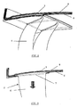
- the figure 2 represents a three-dimensional view of the stator vanes inserted between reinforcement layers of the preform of the outer shell according to a first embodiment of the invention.
- the figure 3 represents a sectional view corresponding to the assembly of the figure 2 .
- the figure 4 represents a front view of a stator vane relative to a wafer inserted between the reinforcing layers of the preform of the outer shell according to a second embodiment of the invention.
- the figure 5 represents a schematic view of three positions of the weld between the pellet and the blade according to the second embodiment of the invention.
- the present invention relates to a method of manufacturing a turbomachine rectifier and, more particularly, to a method of manufacturing a ferrule with integrated blades according to a first embodiment of the invention or reported according to a second embodiment. embodiment of the invention.
- the present invention is illustrated for the manufacture of an outer shell but the method according to the invention is also applicable for the manufacture of an inner shell.
- a first step a ) is to wind the first layers 6 of a reinforcement on a mandrel (not shown) also playing the role of mold and having openings.
- the first reinforcing layers 6 comprise buttonholes 7 arranged opposite the openings.
- the blades 2 and, more particularly, the blade blades 4 are inserted through the buttonholes 7 of the first layers 6 and openings of the mandrel in the direction of the arrow presented to the figure 3 .
- the blade 2 comprises a platform 3 with protuberances (not shown) serving as mechanical anchoring.
- the surface of the platform may also include roughness (not shown) always with the objective of improving its anchoring.
- a third step c) the last reinforcing layers 8 are wound above the blade platforms 3 to complete the preform of the straightener.
- a fourth step d) the mold is closed, a resin is injected around the blade platforms and the impregnated preform is polymerized.
- a fifth and last step e) consists of opening the mold and unmolding the rectifier thus obtained.
- a first step a) consists in winding first layers of a reinforcement 6 on a mandrel (not shown) also acting as a mold and having not openings but protruding parts, such as for example tips, arranged radically at future location of blades.
- the first reinforcing layers 6 comprise buttonholes 7 arranged opposite the projections.
- prefabricated pellets 9 are arranged on the projecting parts. There are as many pellets as blades to attach to the ferrule.
- the pellet 9 comprises protuberances 10, that is to say extensions of the pellet in axial and circumferential directions, these protuberances 10 rest on the first reinforcing layers 6.
- the pellet comprises on its surface asperities (not shown).
- the pellet has protuberances and asperities on its surface.
- the last reinforcing layers 8 are wound over the pellets 9 and their protuberances 10.
- the mold is closed, a resin is injected around the pellets and the impregnated preform is polymerized.
- a fifth step e) is to open the mold and report by welding (11: welding) the blades 2 on the pellets 9. This is the blade platform, if the latter has one, or it is the base the blade of dawn, if the dawn has no platform, which is welded or co-consolidated on the pellet.
- the welding between the pellet 9 and the blade 2 can be performed in different positions as illustrated in FIG. figure 5 .
- the weld 11 is disposed in position 2 or 3, that is to say outside the most mechanically constrained zone namely the inner face of the ferrule (face in the aerodynamic vein).
- the injected resin is preferably a thermosetting resin, for example an epoxy resin, which is in liquid form and comes to embrace the contours and asperities of the platform or lozenge allowing a good anchoring of the latter.
- the polymerization of the resin is carried out at a temperature below that of the melting temperature of the blade or the pellet in order to prevent the latter from becoming soft.
- the blades and the pellets may be made of a thermoplastic or metal material.
- the blades and the pellets are made of a thermoplastic material and, in the second embodiment, the blades are attached to the pellets by thermoplastic welding.
- the blade and the pellet are made with a resin PEEK (Polyetheretherketone), PEKK (Polyetherketoneketone) or PEI (Polyetherimide).
- the reinforcement of the ferrule may consist of braids, fabrics or nonwoven fabrics (known as NCF for Non Crimp Fabrics).
- the blade and the thermoplastic pellet also comprise a reinforcement which may be long, medium or short fibers.
- connection between the blade (or the pellet) and the ferrule is made in a single operation common with the manufacture of the ferrule, this allows to increase the integration at the manufacturing level.
- the process according to the invention allows the production of composite rings and vanes.
- the production of outer shells and composite blades thus generates a weight saving of about 13% compared to a welded joint between outer rings and vanes respectively made of titanium.
- a new blade in case of rupture of a blade, a new blade can easily be attached to the pellet by thermoplastic welding.
Landscapes
- Engineering & Computer Science (AREA)
- Mechanical Engineering (AREA)
- Chemical & Material Sciences (AREA)
- Composite Materials (AREA)
- General Engineering & Computer Science (AREA)
- Structures Of Non-Positive Displacement Pumps (AREA)
- Moulding By Coating Moulds (AREA)
- Turbine Rotor Nozzle Sealing (AREA)
Description
- La présente invention se rapporte à un procédé de fabrication d'un redresseur pour une turbomachine.
- Elle se rapporte plus particulièrement à un procédé de fabrication de viroles intérieures ou extérieures composites avec aubes intégrées ou rapportées.
- Les compresseurs axiaux sont bien connus en soi et sont utilisés entre autres dans les turbomachines.
- Ces compresseurs basse ou haute pression comportent plusieurs étages d'aubes tournantes qui sont séparés par des étages redresseurs qui ont pour but de repositionner le vecteur vitesse du fluide sortant de l'étage précédent avant de l'envoyer vers l'étage suivant.
- Ces étages redresseurs sont constitués essentiellement d'aubes fixes, encore appelées aubes statoriques, reliant une virole extérieure à une virole intérieure, toutes deux concentriques et délimitant la zone d'écoulement d'air ou veine aérodynamique.
- Les aubes statoriques comportent généralement une plateforme qui est fixée à la virole extérieure par rivetage, soudage, boulonnage, collage, etc. Des exemples d'assemblage par rivets (
US 6,543,995 A ) et boulons (EP 1 936 121 A ) sont respectivement illustrés auxfigures 1a et 1b (cf. légende). - On connaît également du document
WO 2008/000014 A2 un arrangement d'aubes directrices disposées entre un anneau interne et un anneau externe. L'arrangement comprend une pluralité de segments où chaque segment d'un seul tenant est formé d'une aube directrice intégrant une partie de l'anneau externe et une partie de l'anneau interne. Chaque partie comporte des brides permettant une fixation avec une structure de turbide. Les segments sont raccordés entre eux par collage ou par le biais d'éléments de raccordement tels que des boulons ou des vis et les brides sont fixées à la structure de turbine également par l'intermédiaire de boulons ou de vis. - L'assemblage par rivets, boulons, etc. a pour inconvénient de nécessiter le perçage d'ouvertures dans la virole pour le passage des éléments de fixation, ce qui entraine une diminution de la résistance structurelle de la virole.
- L'assemblage par collage a pour désavantage de ne pas pouvoir être utilisé comme unique méthode d'assemblage mais toujours en complément d'une autre méthode d'assemblage, par exemple par visserie, et ce pour assurer une meilleure tenue mécanique.
- La présente invention vise à fournir une solution qui permette de s'affranchir des inconvénients de l'état de la technique.
- La présente invention vise en particulier à réaliser un assemblage entre aubes et viroles n'affaiblissant pas la résistance mécanique de la virole.
- La présente invention vise en outre à réaliser un assemblage entre aubes et viroles permettant une réparation aisée des aubes en cas de rupture.
- La présente invention se rapporte à un procédé de fabrication d'un redresseur composite de turbomachine comportant une virole munie d'une pluralité d'aubes statoriques, lesdites aubes statoriques comportant chacune une pale et optionnellement une plateforme, ledit procédé comportant au moins les étapes suivantes:
- a) on bobine des premières couches d'un renfort sur un mandrin, ledit mandrin faisant également office de moule et comportant des parties saillantes, lesdites premières couches de renfort comportant des boutonnières disposées en regard des parties saillantes;
- b) on dispose une pastille préfabriquée sur chacune des parties saillantes;
- c) on bobine des dernières couches de renfort au-dessus des pastilles formant ainsi une préforme;
- d) on injecte une résine dans le moule fermé contenant la préforme et on polymérise la préforme imprégnée de résine;
- e) on sort du moule la préforme polymérisée et on rapporte par soudage la base de la pale ou optionnellement la plateforme de l'aube, si cette dernière en comporte une, sur chacune des pastilles.
- Selon des modes particuliers de l'invention, le procédé comporte au moins une ou une combinaison appropriée des caractéristiques suivantes:
- la pastille préfabriquée et l'aube sont réalisées dans un matériau thermoplastique;
- la pastille préfabriquée et l'aube sont réalisées dans un matériau métallique;
- la pastille comporte des protubérances et/ou des aspérités, lesdites protubérances et aspérités assurant l'ancrage de la pastille dans la préforme;
- l'aube et la pastille comportent un renfort à fibres longues, moyennes ou courtes;
- dans l'étape e), l'aube est rapportée à la pastille par soudage thermoplastique;
- la résine est thermodurcissable;
- la résine est polymérisée à une température inférieure à la température de fusion de la pastille;
- la résine thermodurcissable est une résine époxyde;
- la pastille thermoplastique est en PEEK, en PEKK ou en PEI;
- le renfort comporte des tresses, des tissus ou des tissus non tissés (NCF: Non Crimp Fabrics);
- les parties saillantes comportent des pointes;
- en cas de rupture ou endommagement d'une aube, une nouvelle aube est rapportée à la pastille par soudage;
- la soudure est positionnée sur la face intérieure de la virole ou en dehors de la face intérieure de la virole.
- Les
figures 1a et 1b , déjà mentionnées, représentent respectivement une vue tridimensionnelle et une vue en coupe d'exemples d'assemblage entre aubes statoriques et virole extérieure selon l'état de la technique (cf. légende). - La
figure 2 représente une vue tridimensionnelle des aubes statoriques insérées entre les couches de renfort de la préforme de la virole extérieure selon un premier mode de réalisation de l'invention. - La
figure 3 représente une vue en coupe correspondant à l'assemblage de lafigure 2 . - La
figure 4 représente une vue de face d'une aube statorique rapportée à une pastille insérée entre les couches de renfort de la préforme de la virole extérieure selon un second mode de réalisation de l'invention. - La
figure 5 représente une vue schématique de trois positionnements de la soudure entre la pastille et l'aube selon le second mode de réalisation de l'invention. -
- (1) Bride d'assemblage entre viroles extérieures
- (2) Aube statorique
- (3) Plateforme de l'aube
- (4) Pale de l'aube
- (5) Virole extérieure
- (6) Premières couches du renfort de la préforme de la virole
- (7) Boutonnière sur les premières couches du renfort de la préforme de la virole
- (8) Dernières couches du renfort de la préforme de la virole
- (9) Pastille
- (10) Protubérance de la pastille
- (11) Soudure
- La présente invention concerne un procédé de fabrication d'un redresseur de turbomachine et, plus particulièrement, un procédé de fabrication d'une virole avec des aubes intégrées selon un premier mode de réalisation de l'invention ou rapportées selon un second mode de réalisation de l'invention. La présente invention est illustrée pour la fabrication d'une virole extérieure mais le procédé selon l'invention s'applique également pour la fabrication d'une virole intérieure.
- Selon le premier mode de réalisation illustré aux
figures 2 et 3 , le procédé comporte au moins cinq étapes. Une première étape a) consiste à bobiner les premières couches 6 d'un renfort sur un mandrin (non représenté) jouant également le rôle de moule et comportant des ajours. Les premières couches de renfort 6 comportent des boutonnières 7 disposées en regard des ajours. Dans une deuxième étape b), les aubes 2 et, plus particulièrement, les pales des aubes 4 sont insérées au travers des boutonnières 7 des premières couches 6 et des ajours du mandrin dans le sens de la flèche présentée à lafigure 3 . Préférentiellement, l'aube 2 comporte une plateforme 3 avec des protubérances (non représentées) servant d'ancrage mécanique. La surface de la plateforme peut également comporter des aspérités (non représentées) toujours avec l'objectif d'améliorer son ancrage. Dans une troisième étape c), les dernières couches de renfort 8 sont bobinées au-dessus des plateformes d'aubes 3 pour compléter la préforme du redresseur. Dans une quatrième étape d), le moule est fermé, une résine est injectée autour des plateformes d'aube et la préforme imprégnée est polymérisée. Une cinquième et dernière étape e) consiste à ouvrir le moule et démouler le redresseur ainsi obtenu. - Selon le second mode de réalisation illustré à la
figure 4 , le procédé comporte au moins cinq étapes. Une première étape a) consiste à bobiner des premières couches d'un renfort 6 sur un mandrin (non représenté) jouant également le rôle de moule et comportant non pas des ajours mais des parties saillantes, telles que par exemple des pointes, disposées radicalement au futur emplacement des aubes. Les premières couches de renfort 6 comportent des boutonnières 7 disposées en regard des parties saillantes. Dans une deuxième étape b), des pastilles préfabriquées 9 sont disposées sur les parties saillantes. Il y a autant de pastilles que d'aubes à fixer à la virole. Selon la présente invention, la pastille 9 comporte des protubérances 10, c'est-à-dire des extensions de la pastille dans des directions axiales et circonférentielles, ces protubérances 10 posent sur les premières couches de renfort 6. En variante, la pastille comporte sur sa surface des aspérités (non représentées). Selon encore une autre variante, la pastille comporte des protubérances ainsi que des aspérités sur sa surface. Dans une troisième étape c), les dernières couches de renfort 8 sont bobinées au-dessus des pastilles 9 et de leurs protubérances 10. Dans une quatrième étape d), le moule est fermé, une résine est injectée autour des pastilles et la préforme imprégnée est polymérisée. Une cinquième étape e) consiste à ouvrir le moule et à rapporter par soudage (11: soudure) les aubes 2 sur les pastilles 9. C'est la plateforme d'aube, si cette dernière en comporte une, ou c'est la base de la pale d'aube, si l'aube ne comporte pas de plateforme, qui est soudée ou co-consolidée sur la pastille. Le soudage entre la pastille 9 et l'aube 2 peut être effectué en différentes positions telles qu'illustrées à lafigure 5 . Avantageusement, la soudure 11 est disposée en position 2 ou 3, c'est-à-dire en dehors de la zone la plus contrainte mécaniquement à savoir la face intérieure de la virole (face dans la veine aérodynamique). - Selon les deux modes de réalisation de l'invention susmentionnés, la résine injectée est préférentiellement une résine thermodurcissable, par exemple une résine époxyde, se présentant sous forme liquide et venant embrasser les contours et aspérités de la plateforme ou de la pastille permettant ainsi un bon ancrage de ces dernières. La polymérisation de la résine s'effectue à une température inférieure à celle de la température de fusion de l'aube ou de la pastille afin d'éviter que ces dernières ne se ramollissent. Les aubes ainsi que les pastilles peuvent être réalisées dans un matériau thermoplastique ou métallique. Préférentiellement, les aubes et les pastilles sont réalisées dans un matériau thermoplastique et, dans le second mode de réalisation, les aubes sont rapportées aux pastilles par soudage thermoplastique. A titre d'exemple, l'aube et la pastille sont réalisées avec une résine PEEK (Polyétheréthercétone), PEKK (Polyéthercétonecétone) ou PEI (Polyétherimide). Le renfort de la virole peut être constitué de tresses, de tissus ou de tissus non tissés (dits NCF pour Non Crimp Fabrics). De même, l'aube et la pastille thermoplastique comportent également un renfort qui peut être à fibres longues, moyennes ou courtes.
- Le montage est simplifié car il n'est pas nécessaire d'avoir des éléments de fixation tels que rivets, boulons, etc.
- La liaison entre l'aube (ou la pastille) et la virole est réalisée en une seule opération commune avec la fabrication de la virole, cela permet d'augmenter l'intégration au niveau de la fabrication.
- Le procédé selon J.'invention permet la réalisation de viroles et aubes en composite. La réalisation de viroles extérieures et aubes en composite, engendre ainsi un gain de masse d'environ 13% par rapport à un assemblage soudé entre viroles extérieures et aubes réalisées respectivement en titane.
- Selon le second mode de réalisation de l'invention, en cas de rupture d'une aube, une nouvelle aube peut aisément être rapportée à la pastille par soudage thermoplastique.
- Le placement de la soudure en position 2 et 3 selon le second mode de réalisation permet d'assurer la continuité des fibres de l'aube (position 2) ou de la pastille (position 3) dans la zone la plus contrainte mécaniquement.
Claims (14)
- Procédé de fabrication d'un redresseur composite de turbomachine comportant une virole munie d'une pluralité d'aubes statoriques (2), lesdites aubes statoriques comportant chacune une pale (4) et optionnellement une plateforme (3), ledit procédé comportant au moins les étapes suivantes:a) on bobine des premières couches d'un renfort (6) sur un mandrin, ledit mandrin faisant également office de moule et comportant des parties saillantes, lesdites premières couches de renfort (6) comportant des boutonnières (7) disposées en regard des parties saillantes;b) on dispose une pastille préfabriquée (9) sur chacune des parties saillantes;c) on bobine des dernières couches de renfort (8) au-dessus des pastilles (9) formant ainsi une préforme;d) on injecte une résine dans le moule fermé contenant la préforme et on polymérise la préforme imprégnée de résine;e) on sort du moule la préforme polymérisée et on rapporte par soudage la base de la pale (4) ou optionnellement la plateforme de l'aube (3), si cette dernière en comporte une, sur chacune des pastilles (9).
- Procédé selon la revendication 1, caractérisé en ce que la pastille préfabriquée (9) et l'aube (2) sont réalisées dans un matériau thermoplastique.
- Procédé selon la revendication 1, caractérisé en ce que la pastille préfabriquée (9) et l'aube (2) sont réalisées dans un matériau métallique.
- Procédé selon l'une quelconque des revendications précédentes, caractérisé en ce que la pastille (9) comporte des protubérances (10) et/ou des aspérités, lesdites protubérances et aspérités assurant l'ancrage de la pastille dans la préforme.
- Procédé selon la revendication 2, caractérisée en ce que l'aube (2) et la pastille (9) comportent un renfort à fibres longues, moyennes ou courtes.
- Procédé selon la revendication 2, caractérisé en ce que, dans l'étape e), l'aube (2) est rapportée à la pastille (9) par soudage thermoplastique.
- Procédé selon la revendication 1, caractérisé en ce que la résine est thermodurcissable.
- Procédé selon la revendication 7, caractérisé en ce que la résine est polymérisée à une température inférieure à la température de fusion de la pastille (9).
- Procédé selon la revendication 7, caractérisé en ce que la résine thermodurcissable est une résine époxyde.
- Procédé selon la revendication 2, caractérisé en ce que la pastille thermoplastique (9) est en PEEK, en PEKK ou en PEI.
- Procédé selon la revendication 1, caractérisé en ce que le renfort (6,8) comporte des tresses, des tissus ou des tissus non tissés (NCF: Non Crimp Fabrics).
- Procédé selon la revendication 1, caractérisé en ce que les parties saillantes comportent des pointes.
- Procédé selon la revendication 1, caractérisé en ce que, en cas de rupture ou endommagement d'une aube (2), une nouvelle aube (2) est rapportée à la pastille (9) par soudage.
- Procédé selon la revendication 1, caractérisé en ce que la soudure (11) est positionnée sur la face intérieure de la virole ou en dehors de la face intérieure de la virole.
Priority Applications (5)
| Application Number | Priority Date | Filing Date | Title |
|---|---|---|---|
| EP10159064.4A EP2371521B1 (fr) | 2010-04-02 | 2010-04-02 | Procédé de fabrication d'un redresseur |
| RU2011108051/06A RU2564740C2 (ru) | 2010-04-02 | 2011-03-03 | Способ изготовления спрямляющего аппарата и полученный таким способом спрямляющий аппарат |
| CA2735408A CA2735408C (fr) | 2010-04-02 | 2011-03-28 | Methode de fabrication d'un redresseur |
| US13/075,801 US8807933B2 (en) | 2010-04-02 | 2011-03-30 | Method for manufacturing a rectifier |
| CN201110079341.9A CN102241105B (zh) | 2010-04-02 | 2011-03-31 | 导流器的制作方法 |
Applications Claiming Priority (1)
| Application Number | Priority Date | Filing Date | Title |
|---|---|---|---|
| EP10159064.4A EP2371521B1 (fr) | 2010-04-02 | 2010-04-02 | Procédé de fabrication d'un redresseur |
Publications (2)
| Publication Number | Publication Date |
|---|---|
| EP2371521A1 EP2371521A1 (fr) | 2011-10-05 |
| EP2371521B1 true EP2371521B1 (fr) | 2014-07-02 |
Family
ID=42983542
Family Applications (1)
| Application Number | Title | Priority Date | Filing Date |
|---|---|---|---|
| EP10159064.4A Active EP2371521B1 (fr) | 2010-04-02 | 2010-04-02 | Procédé de fabrication d'un redresseur |
Country Status (5)
| Country | Link |
|---|---|
| US (1) | US8807933B2 (fr) |
| EP (1) | EP2371521B1 (fr) |
| CN (1) | CN102241105B (fr) |
| CA (1) | CA2735408C (fr) |
| RU (1) | RU2564740C2 (fr) |
Families Citing this family (14)
| Publication number | Priority date | Publication date | Assignee | Title |
|---|---|---|---|---|
| US9470243B2 (en) * | 2011-03-09 | 2016-10-18 | Ihi Corporation | Guide vane attachment structure and fan |
| WO2013141941A1 (fr) * | 2011-12-30 | 2013-09-26 | Rolls-Royce Corporation | Turbine à gaz et système d'aubes |
| GB201200845D0 (en) * | 2012-01-19 | 2012-02-29 | Rolls Royce Plc | Method of sealing cooling holes |
| EP2943657B1 (fr) * | 2013-01-14 | 2019-08-14 | United Technologies Corporation | Aube de guidage d'entrée structurale composite matriciel organique pour moteur à turbine |
| EP2971575B1 (fr) | 2013-03-13 | 2017-12-27 | United Technologies Corporation | Gousset en k de diamètre extérieur d'aube de guidage de structure |
| EP3273003B1 (fr) * | 2014-07-07 | 2023-09-06 | Safran Aero Boosters SA | Caisson à aubes de redresseur de compresseur de turbomachine axiale |
| DE102014012562B3 (de) * | 2014-08-29 | 2015-10-08 | Technische Universität München | Verfahren zum Herstellen einer Fügestelle an einem Bauteil aus einem Faserverbundwerkstoff |
| BE1023134B1 (fr) * | 2015-05-27 | 2016-11-29 | Techspace Aero S.A. | Aube et virole a fourreau de compresseur de turbomachine axiale |
| RU2661429C1 (ru) * | 2017-02-06 | 2018-07-16 | Владимир Александрович Грибановский | Способ изготовления направляющего лопаточного аппарата компрессора авиационного двигателя |
| JP6750735B2 (ja) * | 2017-04-25 | 2020-09-02 | 日産自動車株式会社 | 複合材料の成形方法および複合材料の成形装置 |
| CN110435087B (zh) * | 2019-08-09 | 2021-06-29 | 张家港倍恩特磁塑科技有限公司 | 热固性bmc塑封定子包塑模具 |
| PL431184A1 (pl) * | 2019-09-17 | 2021-03-22 | General Electric Company Polska Spółka Z Ograniczoną Odpowiedzialnością | Zespół silnika turbinowego |
| US11333037B2 (en) * | 2020-02-06 | 2022-05-17 | Raytheon Technologies Corporation | Vane arc segment load path |
| CN112009217A (zh) * | 2020-07-23 | 2020-12-01 | 中国第一汽车股份有限公司 | 一种复合材料车门防撞梁及其制备方法 |
Family Cites Families (12)
| Publication number | Priority date | Publication date | Assignee | Title |
|---|---|---|---|---|
| US2995294A (en) * | 1954-12-02 | 1961-08-08 | Studebaker Packard Corp | Stator casing and blade assembly |
| FR2675537B1 (fr) * | 1991-04-17 | 1994-12-02 | Snecma | Aube en composite avec plates-formes surmoulees en polyurethane, pour redresseur de turbomachine. |
| US5820338A (en) | 1997-04-24 | 1998-10-13 | United Technologies Corporation | Fan blade interplatform seal |
| JP4060981B2 (ja) * | 1998-04-08 | 2008-03-12 | 本田技研工業株式会社 | ガスタービンの静翼構造体及びそのユニット |
| US6543995B1 (en) | 1999-08-09 | 2003-04-08 | United Technologies Corporation | Stator vane and stator assembly for a rotary machine |
| RU2293885C1 (ru) * | 2005-08-08 | 2007-02-20 | Открытое акционерное общество Научно-производственное объединение "Искра" | Корпус вентилятора авиационного двигателя |
| FR2890126B1 (fr) * | 2005-08-26 | 2010-10-29 | Snecma | Ensemble et procede pour le montage du pied d'une aube de turbomachine, soufflante, compresseur et turbomachine comportant un tel ensemble |
| AT503840B1 (de) | 2006-06-30 | 2010-09-15 | Facc Ag | Leitschaufelanordnung für ein triebwerk |
| EP1936121B1 (fr) | 2006-12-22 | 2012-05-02 | Techspace Aero | Calage angulaire d'aubes de redresseur de turbomachine |
| DE102006062414A1 (de) * | 2006-12-22 | 2008-06-26 | Technische Universität Dresden | Zylinderrohr für einen Hydraulikzylinder aus Faserverbundwerkstoff und Verfahren zu dessen Herstellung |
| US8894370B2 (en) * | 2008-04-04 | 2014-11-25 | General Electric Company | Turbine blade retention system and method |
| EP2204547B1 (fr) | 2008-12-29 | 2013-12-11 | Techspace Aero | Virole extérieure et procédé de montage par soudage entre cette virole et une aube fixe |
-
2010
- 2010-04-02 EP EP10159064.4A patent/EP2371521B1/fr active Active
-
2011
- 2011-03-03 RU RU2011108051/06A patent/RU2564740C2/ru not_active IP Right Cessation
- 2011-03-28 CA CA2735408A patent/CA2735408C/fr not_active Expired - Fee Related
- 2011-03-30 US US13/075,801 patent/US8807933B2/en not_active Expired - Fee Related
- 2011-03-31 CN CN201110079341.9A patent/CN102241105B/zh not_active Expired - Fee Related
Also Published As
| Publication number | Publication date |
|---|---|
| RU2011108051A (ru) | 2012-09-10 |
| CN102241105A (zh) | 2011-11-16 |
| US8807933B2 (en) | 2014-08-19 |
| CA2735408A1 (fr) | 2011-10-02 |
| US20110243752A1 (en) | 2011-10-06 |
| EP2371521A1 (fr) | 2011-10-05 |
| CA2735408C (fr) | 2017-01-03 |
| RU2564740C2 (ru) | 2015-10-10 |
| CN102241105B (zh) | 2015-09-02 |
Similar Documents
| Publication | Publication Date | Title |
|---|---|---|
| EP2371521B1 (fr) | Procédé de fabrication d'un redresseur | |
| EP2199544B1 (fr) | Architecture de redresseur | |
| EP2472063B1 (fr) | Aube en matériau composite | |
| EP2264284B1 (fr) | Procédé de fabrication d'aubes integrées dans une virole et redresseur obtenu selon le procédé | |
| EP3356650B1 (fr) | Aube comprenant un bouclier de bord d'attaque et procédé de fabrication de l'aube | |
| WO2017109406A1 (fr) | Bouclier de bord d'attaque | |
| WO2020089344A1 (fr) | Hybridation des fibres du renfort fibreux d'une aube de soufflante | |
| EP3578760A1 (fr) | Aube de soufflante en matériau composite avec grand jeu intégré | |
| FR3098246A1 (fr) | Turbine de turbomachine à distributeur en CMC avec reprise d’effort | |
| EP4323624B1 (fr) | Turbine de turbomachine a distributeur en cmc avec reprise d'effort et ajustement de position | |
| EP4127409B1 (fr) | Aube de soufflante rotative de turbomachine, soufflante et turbomachine munies de celle-ci | |
| FR3011269A1 (fr) | Aube de redresseur pour moteur a turbine a gaz a structure hybride | |
| EP2287445A1 (fr) | Tambour de rotor de compresseur axial avec voile composite | |
| EP3983650B1 (fr) | Turbine de turbomachine à distributeur en cmc avec reprise d'effort | |
| FR2950116A1 (fr) | Redresseur de compresseur pour turbomachine, comprenant des tetes d'aubes montees a l'aide d'un materiau amortisseur de vibrations sur la virole exterieure | |
| EP4248095B1 (fr) | Aube comprenant un bouclier ayant une conduite de passage d'air de dégivrage | |
| FR3103215A1 (fr) | Aube de soufflante rotative de turbomachine, soufflante et turbomachine munies de celle-ci | |
| FR3108665A1 (fr) | Rotor de soufflante comprenant des aubes à centre de gravité en amont | |
| EP4473197B1 (fr) | Aube hybride metal/composite a orientation textile adaptee aux sollicitations mecaniques | |
| FR3114348A1 (fr) | Turbine de turbomachine à distributeur en CMC avec reprise d’effort | |
| BE1026460B1 (fr) | Carter structural pour turbomachine axiale | |
| FR2675537A1 (fr) | Aube en composite avec plates-formes surmoulees en polyurethane, pour redresseur de turbomachine. | |
| FR3122697A1 (fr) | Turbine de turbomachine à distributeur en CMC avec maintien en position radiale | |
| FR3156058A1 (fr) | Procédé de fabrication d’une plateforme en matériau composite d’aube de soufflante et plateforme ainsi obtenue | |
| FR3108663A1 (fr) | Aube de soufflante rotative de turbomachine, soufflante et turbomachine munies de celle-ci |
Legal Events
| Date | Code | Title | Description |
|---|---|---|---|
| PUAI | Public reference made under article 153(3) epc to a published international application that has entered the european phase |
Free format text: ORIGINAL CODE: 0009012 |
|
| AK | Designated contracting states |
Kind code of ref document: A1 Designated state(s): AT BE BG CH CY CZ DE DK EE ES FI FR GB GR HR HU IE IS IT LI LT LU LV MC MK MT NL NO PL PT RO SE SI SK SM TR |
|
| AX | Request for extension of the european patent |
Extension state: AL BA ME RS |
|
| 17P | Request for examination filed |
Effective date: 20120329 |
|
| GRAP | Despatch of communication of intention to grant a patent |
Free format text: ORIGINAL CODE: EPIDOSNIGR1 |
|
| RIC1 | Information provided on ipc code assigned before grant |
Ipc: B29C 70/86 20060101ALI20140122BHEP Ipc: B29C 65/02 20060101ALN20140122BHEP Ipc: B29K 63/00 20060101ALN20140122BHEP Ipc: B29C 70/32 20060101ALI20140122BHEP Ipc: F01D 5/28 20060101ALI20140122BHEP Ipc: B29C 53/58 20060101ALI20140122BHEP Ipc: B29C 65/00 20060101ALN20140122BHEP Ipc: F01D 9/04 20060101ALI20140122BHEP Ipc: B29C 70/48 20060101AFI20140122BHEP |
|
| INTG | Intention to grant announced |
Effective date: 20140203 |
|
| GRAS | Grant fee paid |
Free format text: ORIGINAL CODE: EPIDOSNIGR3 |
|
| GRAA | (expected) grant |
Free format text: ORIGINAL CODE: 0009210 |
|
| AK | Designated contracting states |
Kind code of ref document: B1 Designated state(s): AT BE BG CH CY CZ DE DK EE ES FI FR GB GR HR HU IE IS IT LI LT LU LV MC MK MT NL NO PL PT RO SE SI SK SM TR |
|
| REG | Reference to a national code |
Ref country code: GB Ref legal event code: FG4D Free format text: NOT ENGLISH |
|
| REG | Reference to a national code |
Ref country code: CH Ref legal event code: EP Ref country code: AT Ref legal event code: REF Ref document number: 675681 Country of ref document: AT Kind code of ref document: T Effective date: 20140715 |
|
| REG | Reference to a national code |
Ref country code: IE Ref legal event code: FG4D Free format text: LANGUAGE OF EP DOCUMENT: FRENCH |
|
| REG | Reference to a national code |
Ref country code: DE Ref legal event code: R096 Ref document number: 602010017153 Country of ref document: DE Effective date: 20140814 |
|
| REG | Reference to a national code |
Ref country code: AT Ref legal event code: MK05 Ref document number: 675681 Country of ref document: AT Kind code of ref document: T Effective date: 20140702 |
|
| REG | Reference to a national code |
Ref country code: NL Ref legal event code: VDEP Effective date: 20140702 |
|
| REG | Reference to a national code |
Ref country code: LT Ref legal event code: MG4D |
|
| PG25 | Lapsed in a contracting state [announced via postgrant information from national office to epo] |
Ref country code: CZ Free format text: LAPSE BECAUSE OF FAILURE TO SUBMIT A TRANSLATION OF THE DESCRIPTION OR TO PAY THE FEE WITHIN THE PRESCRIBED TIME-LIMIT Effective date: 20140702 Ref country code: NO Free format text: LAPSE BECAUSE OF FAILURE TO SUBMIT A TRANSLATION OF THE DESCRIPTION OR TO PAY THE FEE WITHIN THE PRESCRIBED TIME-LIMIT Effective date: 20141002 Ref country code: ES Free format text: LAPSE BECAUSE OF FAILURE TO SUBMIT A TRANSLATION OF THE DESCRIPTION OR TO PAY THE FEE WITHIN THE PRESCRIBED TIME-LIMIT Effective date: 20140702 Ref country code: BG Free format text: LAPSE BECAUSE OF FAILURE TO SUBMIT A TRANSLATION OF THE DESCRIPTION OR TO PAY THE FEE WITHIN THE PRESCRIBED TIME-LIMIT Effective date: 20141002 Ref country code: SE Free format text: LAPSE BECAUSE OF FAILURE TO SUBMIT A TRANSLATION OF THE DESCRIPTION OR TO PAY THE FEE WITHIN THE PRESCRIBED TIME-LIMIT Effective date: 20140702 Ref country code: FI Free format text: LAPSE BECAUSE OF FAILURE TO SUBMIT A TRANSLATION OF THE DESCRIPTION OR TO PAY THE FEE WITHIN THE PRESCRIBED TIME-LIMIT Effective date: 20140702 Ref country code: PT Free format text: LAPSE BECAUSE OF FAILURE TO SUBMIT A TRANSLATION OF THE DESCRIPTION OR TO PAY THE FEE WITHIN THE PRESCRIBED TIME-LIMIT Effective date: 20141103 Ref country code: LT Free format text: LAPSE BECAUSE OF FAILURE TO SUBMIT A TRANSLATION OF THE DESCRIPTION OR TO PAY THE FEE WITHIN THE PRESCRIBED TIME-LIMIT Effective date: 20140702 Ref country code: GR Free format text: LAPSE BECAUSE OF FAILURE TO SUBMIT A TRANSLATION OF THE DESCRIPTION OR TO PAY THE FEE WITHIN THE PRESCRIBED TIME-LIMIT Effective date: 20141003 |
|
| PG25 | Lapsed in a contracting state [announced via postgrant information from national office to epo] |
Ref country code: NL Free format text: LAPSE BECAUSE OF FAILURE TO SUBMIT A TRANSLATION OF THE DESCRIPTION OR TO PAY THE FEE WITHIN THE PRESCRIBED TIME-LIMIT Effective date: 20140702 Ref country code: LV Free format text: LAPSE BECAUSE OF FAILURE TO SUBMIT A TRANSLATION OF THE DESCRIPTION OR TO PAY THE FEE WITHIN THE PRESCRIBED TIME-LIMIT Effective date: 20140702 Ref country code: IS Free format text: LAPSE BECAUSE OF FAILURE TO SUBMIT A TRANSLATION OF THE DESCRIPTION OR TO PAY THE FEE WITHIN THE PRESCRIBED TIME-LIMIT Effective date: 20141102 Ref country code: PL Free format text: LAPSE BECAUSE OF FAILURE TO SUBMIT A TRANSLATION OF THE DESCRIPTION OR TO PAY THE FEE WITHIN THE PRESCRIBED TIME-LIMIT Effective date: 20140702 Ref country code: CY Free format text: LAPSE BECAUSE OF FAILURE TO SUBMIT A TRANSLATION OF THE DESCRIPTION OR TO PAY THE FEE WITHIN THE PRESCRIBED TIME-LIMIT Effective date: 20140702 Ref country code: HR Free format text: LAPSE BECAUSE OF FAILURE TO SUBMIT A TRANSLATION OF THE DESCRIPTION OR TO PAY THE FEE WITHIN THE PRESCRIBED TIME-LIMIT Effective date: 20140702 Ref country code: AT Free format text: LAPSE BECAUSE OF FAILURE TO SUBMIT A TRANSLATION OF THE DESCRIPTION OR TO PAY THE FEE WITHIN THE PRESCRIBED TIME-LIMIT Effective date: 20140702 |
|
| REG | Reference to a national code |
Ref country code: DE Ref legal event code: R097 Ref document number: 602010017153 Country of ref document: DE |
|
| PG25 | Lapsed in a contracting state [announced via postgrant information from national office to epo] |
Ref country code: RO Free format text: LAPSE BECAUSE OF FAILURE TO SUBMIT A TRANSLATION OF THE DESCRIPTION OR TO PAY THE FEE WITHIN THE PRESCRIBED TIME-LIMIT Effective date: 20140702 Ref country code: EE Free format text: LAPSE BECAUSE OF FAILURE TO SUBMIT A TRANSLATION OF THE DESCRIPTION OR TO PAY THE FEE WITHIN THE PRESCRIBED TIME-LIMIT Effective date: 20140702 Ref country code: IT Free format text: LAPSE BECAUSE OF FAILURE TO SUBMIT A TRANSLATION OF THE DESCRIPTION OR TO PAY THE FEE WITHIN THE PRESCRIBED TIME-LIMIT Effective date: 20140702 Ref country code: SK Free format text: LAPSE BECAUSE OF FAILURE TO SUBMIT A TRANSLATION OF THE DESCRIPTION OR TO PAY THE FEE WITHIN THE PRESCRIBED TIME-LIMIT Effective date: 20140702 Ref country code: DK Free format text: LAPSE BECAUSE OF FAILURE TO SUBMIT A TRANSLATION OF THE DESCRIPTION OR TO PAY THE FEE WITHIN THE PRESCRIBED TIME-LIMIT Effective date: 20140702 |
|
| PLBE | No opposition filed within time limit |
Free format text: ORIGINAL CODE: 0009261 |
|
| STAA | Information on the status of an ep patent application or granted ep patent |
Free format text: STATUS: NO OPPOSITION FILED WITHIN TIME LIMIT |
|
| 26N | No opposition filed |
Effective date: 20150407 |
|
| PG25 | Lapsed in a contracting state [announced via postgrant information from national office to epo] |
Ref country code: MC Free format text: LAPSE BECAUSE OF FAILURE TO SUBMIT A TRANSLATION OF THE DESCRIPTION OR TO PAY THE FEE WITHIN THE PRESCRIBED TIME-LIMIT Effective date: 20140702 Ref country code: LU Free format text: LAPSE BECAUSE OF FAILURE TO SUBMIT A TRANSLATION OF THE DESCRIPTION OR TO PAY THE FEE WITHIN THE PRESCRIBED TIME-LIMIT Effective date: 20150402 Ref country code: SI Free format text: LAPSE BECAUSE OF FAILURE TO SUBMIT A TRANSLATION OF THE DESCRIPTION OR TO PAY THE FEE WITHIN THE PRESCRIBED TIME-LIMIT Effective date: 20140702 |
|
| REG | Reference to a national code |
Ref country code: CH Ref legal event code: PL |
|
| REG | Reference to a national code |
Ref country code: IE Ref legal event code: MM4A |
|
| PG25 | Lapsed in a contracting state [announced via postgrant information from national office to epo] |
Ref country code: CH Free format text: LAPSE BECAUSE OF NON-PAYMENT OF DUE FEES Effective date: 20150430 Ref country code: LI Free format text: LAPSE BECAUSE OF NON-PAYMENT OF DUE FEES Effective date: 20150430 |
|
| REG | Reference to a national code |
Ref country code: FR Ref legal event code: PLFP Year of fee payment: 7 |
|
| PG25 | Lapsed in a contracting state [announced via postgrant information from national office to epo] |
Ref country code: IE Free format text: LAPSE BECAUSE OF NON-PAYMENT OF DUE FEES Effective date: 20150402 |
|
| PG25 | Lapsed in a contracting state [announced via postgrant information from national office to epo] |
Ref country code: MT Free format text: LAPSE BECAUSE OF FAILURE TO SUBMIT A TRANSLATION OF THE DESCRIPTION OR TO PAY THE FEE WITHIN THE PRESCRIBED TIME-LIMIT Effective date: 20140702 |
|
| REG | Reference to a national code |
Ref country code: FR Ref legal event code: PLFP Year of fee payment: 8 |
|
| PG25 | Lapsed in a contracting state [announced via postgrant information from national office to epo] |
Ref country code: HU Free format text: LAPSE BECAUSE OF FAILURE TO SUBMIT A TRANSLATION OF THE DESCRIPTION OR TO PAY THE FEE WITHIN THE PRESCRIBED TIME-LIMIT; INVALID AB INITIO Effective date: 20100402 Ref country code: SM Free format text: LAPSE BECAUSE OF FAILURE TO SUBMIT A TRANSLATION OF THE DESCRIPTION OR TO PAY THE FEE WITHIN THE PRESCRIBED TIME-LIMIT Effective date: 20140702 |
|
| PG25 | Lapsed in a contracting state [announced via postgrant information from national office to epo] |
Ref country code: TR Free format text: LAPSE BECAUSE OF FAILURE TO SUBMIT A TRANSLATION OF THE DESCRIPTION OR TO PAY THE FEE WITHIN THE PRESCRIBED TIME-LIMIT Effective date: 20140702 |
|
| REG | Reference to a national code |
Ref country code: FR Ref legal event code: PLFP Year of fee payment: 9 |
|
| PG25 | Lapsed in a contracting state [announced via postgrant information from national office to epo] |
Ref country code: MK Free format text: LAPSE BECAUSE OF FAILURE TO SUBMIT A TRANSLATION OF THE DESCRIPTION OR TO PAY THE FEE WITHIN THE PRESCRIBED TIME-LIMIT Effective date: 20140702 |
|
| PGFP | Annual fee paid to national office [announced via postgrant information from national office to epo] |
Ref country code: GB Payment date: 20190325 Year of fee payment: 10 |
|
| PGFP | Annual fee paid to national office [announced via postgrant information from national office to epo] |
Ref country code: DE Payment date: 20190220 Year of fee payment: 10 |
|
| REG | Reference to a national code |
Ref country code: DE Ref legal event code: R119 Ref document number: 602010017153 Country of ref document: DE |
|
| PG25 | Lapsed in a contracting state [announced via postgrant information from national office to epo] |
Ref country code: DE Free format text: LAPSE BECAUSE OF NON-PAYMENT OF DUE FEES Effective date: 20201103 |
|
| GBPC | Gb: european patent ceased through non-payment of renewal fee |
Effective date: 20200402 |
|
| PG25 | Lapsed in a contracting state [announced via postgrant information from national office to epo] |
Ref country code: GB Free format text: LAPSE BECAUSE OF NON-PAYMENT OF DUE FEES Effective date: 20200402 |
|
| PGFP | Annual fee paid to national office [announced via postgrant information from national office to epo] |
Ref country code: BE Payment date: 20250417 Year of fee payment: 16 |
|
| PGFP | Annual fee paid to national office [announced via postgrant information from national office to epo] |
Ref country code: FR Payment date: 20250428 Year of fee payment: 16 |