EP2371565A2 - Procédé de formation d'image et dispositif d'enregistrement à jet d'encre - Google Patents
Procédé de formation d'image et dispositif d'enregistrement à jet d'encre Download PDFInfo
- Publication number
- EP2371565A2 EP2371565A2 EP20110160185 EP11160185A EP2371565A2 EP 2371565 A2 EP2371565 A2 EP 2371565A2 EP 20110160185 EP20110160185 EP 20110160185 EP 11160185 A EP11160185 A EP 11160185A EP 2371565 A2 EP2371565 A2 EP 2371565A2
- Authority
- EP
- European Patent Office
- Prior art keywords
- curable ink
- radiation
- radiation curable
- active radiation
- irradiation energy
- Prior art date
- Legal status (The legal status is an assumption and is not a legal conclusion. Google has not performed a legal analysis and makes no representation as to the accuracy of the status listed.)
- Granted
Links
- 238000000034 method Methods 0.000 title claims abstract description 122
- 230000005855 radiation Effects 0.000 claims abstract description 374
- 239000007788 liquid Substances 0.000 claims abstract description 213
- 239000000203 mixture Substances 0.000 claims abstract description 192
- 230000008569 process Effects 0.000 claims abstract description 50
- 230000001678 irradiating effect Effects 0.000 claims abstract description 15
- 230000015572 biosynthetic process Effects 0.000 claims description 17
- 239000000976 ink Substances 0.000 description 246
- NIXOWILDQLNWCW-UHFFFAOYSA-M Acrylate Chemical compound [O-]C(=O)C=C NIXOWILDQLNWCW-UHFFFAOYSA-M 0.000 description 54
- 239000000049 pigment Substances 0.000 description 43
- 230000000740 bleeding effect Effects 0.000 description 25
- 239000003999 initiator Substances 0.000 description 24
- 239000000463 material Substances 0.000 description 24
- 230000000052 comparative effect Effects 0.000 description 22
- 230000002349 favourable effect Effects 0.000 description 22
- -1 (2-methyl-2-ethyl-1,3-dioxolane-4-yl)methyl Chemical group 0.000 description 21
- 238000011156 evaluation Methods 0.000 description 20
- 150000001875 compounds Chemical class 0.000 description 17
- 239000007787 solid Substances 0.000 description 17
- 229920002799 BoPET Polymers 0.000 description 16
- 239000003086 colorant Substances 0.000 description 12
- LYCAIKOWRPUZTN-UHFFFAOYSA-N ethylene glycol Natural products OCCO LYCAIKOWRPUZTN-UHFFFAOYSA-N 0.000 description 11
- 238000007639 printing Methods 0.000 description 11
- 238000009472 formulation Methods 0.000 description 9
- 239000000126 substance Substances 0.000 description 9
- 239000000178 monomer Substances 0.000 description 8
- 239000000123 paper Substances 0.000 description 8
- 238000010521 absorption reaction Methods 0.000 description 7
- 239000002270 dispersing agent Substances 0.000 description 7
- 239000003795 chemical substances by application Substances 0.000 description 6
- 239000006185 dispersion Substances 0.000 description 6
- WGCNASOHLSPBMP-UHFFFAOYSA-N hydroxyacetaldehyde Natural products OCC=O WGCNASOHLSPBMP-UHFFFAOYSA-N 0.000 description 6
- 239000003112 inhibitor Substances 0.000 description 6
- 238000006116 polymerization reaction Methods 0.000 description 6
- 238000002360 preparation method Methods 0.000 description 6
- 238000012360 testing method Methods 0.000 description 6
- JOYRKODLDBILNP-UHFFFAOYSA-N Ethyl urethane Chemical compound CCOC(N)=O JOYRKODLDBILNP-UHFFFAOYSA-N 0.000 description 5
- IAYPIBMASNFSPL-UHFFFAOYSA-N Ethylene oxide Chemical compound C1CO1 IAYPIBMASNFSPL-UHFFFAOYSA-N 0.000 description 5
- 229920001296 polysiloxane Polymers 0.000 description 5
- YTLYLLTVENPWFT-UPHRSURJSA-N (Z)-3-aminoacrylic acid Chemical compound N\C=C/C(O)=O YTLYLLTVENPWFT-UPHRSURJSA-N 0.000 description 4
- JWYVGKFDLWWQJX-UHFFFAOYSA-N 1-ethenylazepan-2-one Chemical compound C=CN1CCCCCC1=O JWYVGKFDLWWQJX-UHFFFAOYSA-N 0.000 description 4
- ZJCCRDAZUWHFQH-UHFFFAOYSA-N Trimethylolpropane Chemical compound CCC(CO)(CO)CO ZJCCRDAZUWHFQH-UHFFFAOYSA-N 0.000 description 4
- MCMNRKCIXSYSNV-UHFFFAOYSA-N Zirconium dioxide Chemical compound O=[Zr]=O MCMNRKCIXSYSNV-UHFFFAOYSA-N 0.000 description 4
- 230000001588 bifunctional effect Effects 0.000 description 4
- VFHVQBAGLAREND-UHFFFAOYSA-N diphenylphosphoryl-(2,4,6-trimethylphenyl)methanone Chemical compound CC1=CC(C)=CC(C)=C1C(=O)P(=O)(C=1C=CC=CC=1)C1=CC=CC=C1 VFHVQBAGLAREND-UHFFFAOYSA-N 0.000 description 4
- UHESRSKEBRADOO-UHFFFAOYSA-N ethyl carbamate;prop-2-enoic acid Chemical compound OC(=O)C=C.CCOC(N)=O UHESRSKEBRADOO-UHFFFAOYSA-N 0.000 description 4
- ZFSLODLOARCGLH-UHFFFAOYSA-N isocyanuric acid Chemical compound OC1=NC(O)=NC(O)=N1 ZFSLODLOARCGLH-UHFFFAOYSA-N 0.000 description 4
- 238000004519 manufacturing process Methods 0.000 description 4
- 229920003023 plastic Polymers 0.000 description 4
- 239000004033 plastic Substances 0.000 description 4
- 230000009467 reduction Effects 0.000 description 4
- YRHRIQCWCFGUEQ-UHFFFAOYSA-N thioxanthen-9-one Chemical compound C1=CC=C2C(=O)C3=CC=CC=C3SC2=C1 YRHRIQCWCFGUEQ-UHFFFAOYSA-N 0.000 description 4
- OKTJSMMVPCPJKN-UHFFFAOYSA-N Carbon Chemical compound [C] OKTJSMMVPCPJKN-UHFFFAOYSA-N 0.000 description 3
- WSFSSNUMVMOOMR-UHFFFAOYSA-N Formaldehyde Chemical compound O=C WSFSSNUMVMOOMR-UHFFFAOYSA-N 0.000 description 3
- 238000005033 Fourier transform infrared spectroscopy Methods 0.000 description 3
- DNIAPMSPPWPWGF-UHFFFAOYSA-N Propylene glycol Chemical compound CC(O)CO DNIAPMSPPWPWGF-UHFFFAOYSA-N 0.000 description 3
- 150000001252 acrylic acid derivatives Chemical class 0.000 description 3
- 239000000654 additive Substances 0.000 description 3
- QVGXLLKOCUKJST-UHFFFAOYSA-N atomic oxygen Chemical compound [O] QVGXLLKOCUKJST-UHFFFAOYSA-N 0.000 description 3
- IISBACLAFKSPIT-UHFFFAOYSA-N bisphenol A Chemical compound C=1C=C(O)C=CC=1C(C)(C)C1=CC=C(O)C=C1 IISBACLAFKSPIT-UHFFFAOYSA-N 0.000 description 3
- 230000007423 decrease Effects 0.000 description 3
- 238000011161 development Methods 0.000 description 3
- MTHSVFCYNBDYFN-UHFFFAOYSA-N diethylene glycol Chemical compound OCCOCCO MTHSVFCYNBDYFN-UHFFFAOYSA-N 0.000 description 3
- 238000005259 measurement Methods 0.000 description 3
- 238000002156 mixing Methods 0.000 description 3
- 239000001301 oxygen Substances 0.000 description 3
- 229910052760 oxygen Inorganic materials 0.000 description 3
- NWVVVBRKAWDGAB-UHFFFAOYSA-N p-methoxyphenol Chemical compound COC1=CC=C(O)C=C1 NWVVVBRKAWDGAB-UHFFFAOYSA-N 0.000 description 3
- 239000003504 photosensitizing agent Substances 0.000 description 3
- 229920001223 polyethylene glycol Polymers 0.000 description 3
- 238000010998 test method Methods 0.000 description 3
- DTGKSKDOIYIVQL-WEDXCCLWSA-N (+)-borneol Chemical group C1C[C@@]2(C)[C@@H](O)C[C@@H]1C2(C)C DTGKSKDOIYIVQL-WEDXCCLWSA-N 0.000 description 2
- PUPZLCDOIYMWBV-UHFFFAOYSA-N (+/-)-1,3-Butanediol Chemical compound CC(O)CCO PUPZLCDOIYMWBV-UHFFFAOYSA-N 0.000 description 2
- ALVZNPYWJMLXKV-UHFFFAOYSA-N 1,9-Nonanediol Chemical compound OCCCCCCCCCO ALVZNPYWJMLXKV-UHFFFAOYSA-N 0.000 description 2
- ZDQNWDNMNKSMHI-UHFFFAOYSA-N 1-[2-(2-prop-2-enoyloxypropoxy)propoxy]propan-2-yl prop-2-enoate Chemical compound C=CC(=O)OC(C)COC(C)COCC(C)OC(=O)C=C ZDQNWDNMNKSMHI-UHFFFAOYSA-N 0.000 description 2
- BTJPUDCSZVCXFQ-UHFFFAOYSA-N 2,4-diethylthioxanthen-9-one Chemical compound C1=CC=C2C(=O)C3=CC(CC)=CC(CC)=C3SC2=C1 BTJPUDCSZVCXFQ-UHFFFAOYSA-N 0.000 description 2
- KDSNLYIMUZNERS-UHFFFAOYSA-N 2-methylpropanamine Chemical compound CC(C)CN KDSNLYIMUZNERS-UHFFFAOYSA-N 0.000 description 2
- RZVINYQDSSQUKO-UHFFFAOYSA-N 2-phenoxyethyl prop-2-enoate Chemical compound C=CC(=O)OCCOC1=CC=CC=C1 RZVINYQDSSQUKO-UHFFFAOYSA-N 0.000 description 2
- VVBLNCFGVYUYGU-UHFFFAOYSA-N 4,4'-Bis(dimethylamino)benzophenone Chemical compound C1=CC(N(C)C)=CC=C1C(=O)C1=CC=C(N(C)C)C=C1 VVBLNCFGVYUYGU-UHFFFAOYSA-N 0.000 description 2
- IKHGUXGNUITLKF-UHFFFAOYSA-N Acetaldehyde Chemical compound CC=O IKHGUXGNUITLKF-UHFFFAOYSA-N 0.000 description 2
- QUSNBJAOOMFDIB-UHFFFAOYSA-N Ethylamine Chemical compound CCN QUSNBJAOOMFDIB-UHFFFAOYSA-N 0.000 description 2
- PEDCQBHIVMGVHV-UHFFFAOYSA-N Glycerine Chemical compound OCC(O)CO PEDCQBHIVMGVHV-UHFFFAOYSA-N 0.000 description 2
- QIGBRXMKCJKVMJ-UHFFFAOYSA-N Hydroquinone Chemical compound OC1=CC=C(O)C=C1 QIGBRXMKCJKVMJ-UHFFFAOYSA-N 0.000 description 2
- UQSXHKLRYXJYBZ-UHFFFAOYSA-N Iron oxide Chemical compound [Fe]=O UQSXHKLRYXJYBZ-UHFFFAOYSA-N 0.000 description 2
- BHHGXPLMPWCGHP-UHFFFAOYSA-N Phenethylamine Chemical compound NCCC1=CC=CC=C1 BHHGXPLMPWCGHP-UHFFFAOYSA-N 0.000 description 2
- NQRYJNQNLNOLGT-UHFFFAOYSA-N Piperidine Chemical compound C1CCNCC1 NQRYJNQNLNOLGT-UHFFFAOYSA-N 0.000 description 2
- 239000002202 Polyethylene glycol Substances 0.000 description 2
- GWEVSGVZZGPLCZ-UHFFFAOYSA-N Titan oxide Chemical compound O=[Ti]=O GWEVSGVZZGPLCZ-UHFFFAOYSA-N 0.000 description 2
- XLOMVQKBTHCTTD-UHFFFAOYSA-N Zinc monoxide Chemical compound [Zn]=O XLOMVQKBTHCTTD-UHFFFAOYSA-N 0.000 description 2
- GUCYFKSBFREPBC-UHFFFAOYSA-N [phenyl-(2,4,6-trimethylbenzoyl)phosphoryl]-(2,4,6-trimethylphenyl)methanone Chemical compound CC1=CC(C)=CC(C)=C1C(=O)P(=O)(C=1C=CC=CC=1)C(=O)C1=C(C)C=C(C)C=C1C GUCYFKSBFREPBC-UHFFFAOYSA-N 0.000 description 2
- 238000000862 absorption spectrum Methods 0.000 description 2
- 125000002723 alicyclic group Chemical group 0.000 description 2
- 150000001412 amines Chemical class 0.000 description 2
- 125000003118 aryl group Chemical group 0.000 description 2
- 239000011324 bead Substances 0.000 description 2
- WGQKYBSKWIADBV-UHFFFAOYSA-N benzylamine Chemical compound NCC1=CC=CC=C1 WGQKYBSKWIADBV-UHFFFAOYSA-N 0.000 description 2
- PXKLMJQFEQBVLD-UHFFFAOYSA-N bisphenol F Chemical compound C1=CC(O)=CC=C1CC1=CC=C(O)C=C1 PXKLMJQFEQBVLD-UHFFFAOYSA-N 0.000 description 2
- WERYXYBDKMZEQL-UHFFFAOYSA-N butane-1,4-diol Chemical compound OCCCCO WERYXYBDKMZEQL-UHFFFAOYSA-N 0.000 description 2
- 239000006229 carbon black Substances 0.000 description 2
- 230000008859 change Effects 0.000 description 2
- 238000006243 chemical reaction Methods 0.000 description 2
- PAFZNILMFXTMIY-UHFFFAOYSA-N cyclohexylamine Chemical compound NC1CCCCC1 PAFZNILMFXTMIY-UHFFFAOYSA-N 0.000 description 2
- 150000004985 diamines Chemical class 0.000 description 2
- 238000001035 drying Methods 0.000 description 2
- 230000000694 effects Effects 0.000 description 2
- NAQMVNRVTILPCV-UHFFFAOYSA-N hexane-1,6-diamine Chemical compound NCCCCCCN NAQMVNRVTILPCV-UHFFFAOYSA-N 0.000 description 2
- XXMIOPMDWAUFGU-UHFFFAOYSA-N hexane-1,6-diol Chemical compound OCCCCCCO XXMIOPMDWAUFGU-UHFFFAOYSA-N 0.000 description 2
- 230000000977 initiatory effect Effects 0.000 description 2
- 239000001023 inorganic pigment Substances 0.000 description 2
- BMFVGAAISNGQNM-UHFFFAOYSA-N isopentylamine Chemical compound CC(C)CCN BMFVGAAISNGQNM-UHFFFAOYSA-N 0.000 description 2
- LUCXVPAZUDVVBT-UHFFFAOYSA-N methyl-[3-(2-methylphenoxy)-3-phenylpropyl]azanium;chloride Chemical compound Cl.C=1C=CC=CC=1C(CCNC)OC1=CC=CC=C1C LUCXVPAZUDVVBT-UHFFFAOYSA-N 0.000 description 2
- SLCVBVWXLSEKPL-UHFFFAOYSA-N neopentyl glycol Chemical compound OCC(C)(C)CO SLCVBVWXLSEKPL-UHFFFAOYSA-N 0.000 description 2
- 230000003287 optical effect Effects 0.000 description 2
- 239000012860 organic pigment Substances 0.000 description 2
- 239000002245 particle Substances 0.000 description 2
- DPBLXKKOBLCELK-UHFFFAOYSA-N pentan-1-amine Chemical compound CCCCCN DPBLXKKOBLCELK-UHFFFAOYSA-N 0.000 description 2
- 239000002985 plastic film Substances 0.000 description 2
- 229920006255 plastic film Polymers 0.000 description 2
- BASFCYQUMIYNBI-UHFFFAOYSA-N platinum Chemical compound [Pt] BASFCYQUMIYNBI-UHFFFAOYSA-N 0.000 description 2
- 229920005862 polyol Polymers 0.000 description 2
- WGYKZJWCGVVSQN-UHFFFAOYSA-N propylamine Chemical compound CCCN WGYKZJWCGVVSQN-UHFFFAOYSA-N 0.000 description 2
- RSVDRWTUCMTKBV-UHFFFAOYSA-N sbb057044 Chemical compound C12CC=CC2C2CC(OCCOC(=O)C=C)C1C2 RSVDRWTUCMTKBV-UHFFFAOYSA-N 0.000 description 2
- VZGDMQKNWNREIO-UHFFFAOYSA-N tetrachloromethane Chemical compound ClC(Cl)(Cl)Cl VZGDMQKNWNREIO-UHFFFAOYSA-N 0.000 description 2
- OGIDPMRJRNCKJF-UHFFFAOYSA-N titanium oxide Inorganic materials [Ti]=O OGIDPMRJRNCKJF-UHFFFAOYSA-N 0.000 description 2
- 239000001052 yellow pigment Substances 0.000 description 2
- SZCWBURCISJFEZ-UHFFFAOYSA-N (3-hydroxy-2,2-dimethylpropyl) 3-hydroxy-2,2-dimethylpropanoate Chemical compound OCC(C)(C)COC(=O)C(C)(C)CO SZCWBURCISJFEZ-UHFFFAOYSA-N 0.000 description 1
- PYOLJOJPIPCRDP-UHFFFAOYSA-N 1,1,3-trimethylcyclohexane Chemical compound CC1CCCC(C)(C)C1 PYOLJOJPIPCRDP-UHFFFAOYSA-N 0.000 description 1
- GJZFGDYLJLCGHT-UHFFFAOYSA-N 1,2-diethylthioxanthen-9-one Chemical compound C1=CC=C2C(=O)C3=C(CC)C(CC)=CC=C3SC2=C1 GJZFGDYLJLCGHT-UHFFFAOYSA-N 0.000 description 1
- GEYOCULIXLDCMW-UHFFFAOYSA-N 1,2-phenylenediamine Chemical compound NC1=CC=CC=C1N GEYOCULIXLDCMW-UHFFFAOYSA-N 0.000 description 1
- 229940058015 1,3-butylene glycol Drugs 0.000 description 1
- WZCQRUWWHSTZEM-UHFFFAOYSA-N 1,3-phenylenediamine Chemical compound NC1=CC=CC(N)=C1 WZCQRUWWHSTZEM-UHFFFAOYSA-N 0.000 description 1
- RYHBNJHYFVUHQT-UHFFFAOYSA-N 1,4-Dioxane Chemical compound C1COCCO1 RYHBNJHYFVUHQT-UHFFFAOYSA-N 0.000 description 1
- AZQWKYJCGOJGHM-UHFFFAOYSA-N 1,4-benzoquinone Chemical compound O=C1C=CC(=O)C=C1 AZQWKYJCGOJGHM-UHFFFAOYSA-N 0.000 description 1
- CBCKQZAAMUWICA-UHFFFAOYSA-N 1,4-phenylenediamine Chemical compound NC1=CC=C(N)C=C1 CBCKQZAAMUWICA-UHFFFAOYSA-N 0.000 description 1
- PWGJDPKCLMLPJW-UHFFFAOYSA-N 1,8-diaminooctane Chemical compound NCCCCCCCCN PWGJDPKCLMLPJW-UHFFFAOYSA-N 0.000 description 1
- FJLUATLTXUNBOT-UHFFFAOYSA-N 1-Hexadecylamine Chemical compound CCCCCCCCCCCCCCCCN FJLUATLTXUNBOT-UHFFFAOYSA-N 0.000 description 1
- BMVXCPBXGZKUPN-UHFFFAOYSA-N 1-hexanamine Chemical compound CCCCCCN BMVXCPBXGZKUPN-UHFFFAOYSA-N 0.000 description 1
- XLPJNCYCZORXHG-UHFFFAOYSA-N 1-morpholin-4-ylprop-2-en-1-one Chemical compound C=CC(=O)N1CCOCC1 XLPJNCYCZORXHG-UHFFFAOYSA-N 0.000 description 1
- VILCJCGEZXAXTO-UHFFFAOYSA-N 2,2,2-tetramine Chemical compound NCCNCCNCCN VILCJCGEZXAXTO-UHFFFAOYSA-N 0.000 description 1
- YHYCMHWTYHPIQS-UHFFFAOYSA-N 2-(2-hydroxyethoxy)-1-methoxyethanol Chemical compound COC(O)COCCO YHYCMHWTYHPIQS-UHFFFAOYSA-N 0.000 description 1
- FWLHAQYOFMQTHQ-UHFFFAOYSA-N 2-N-[8-[[8-(4-aminoanilino)-10-phenylphenazin-10-ium-2-yl]amino]-10-phenylphenazin-10-ium-2-yl]-8-N,10-diphenylphenazin-10-ium-2,8-diamine hydroxy-oxido-dioxochromium Chemical compound O[Cr]([O-])(=O)=O.O[Cr]([O-])(=O)=O.O[Cr]([O-])(=O)=O.Nc1ccc(Nc2ccc3nc4ccc(Nc5ccc6nc7ccc(Nc8ccc9nc%10ccc(Nc%11ccccc%11)cc%10[n+](-c%10ccccc%10)c9c8)cc7[n+](-c7ccccc7)c6c5)cc4[n+](-c4ccccc4)c3c2)cc1 FWLHAQYOFMQTHQ-UHFFFAOYSA-N 0.000 description 1
- LCZVSXRMYJUNFX-UHFFFAOYSA-N 2-[2-(2-hydroxypropoxy)propoxy]propan-1-ol Chemical compound CC(O)COC(C)COC(C)CO LCZVSXRMYJUNFX-UHFFFAOYSA-N 0.000 description 1
- LTHNHFOGQMKPOV-UHFFFAOYSA-N 2-ethylhexan-1-amine Chemical compound CCCCC(CC)CN LTHNHFOGQMKPOV-UHFFFAOYSA-N 0.000 description 1
- RNLHGQLZWXBQNY-UHFFFAOYSA-N 3-(aminomethyl)-3,5,5-trimethylcyclohexan-1-amine Chemical compound CC1(C)CC(N)CC(C)(CN)C1 RNLHGQLZWXBQNY-UHFFFAOYSA-N 0.000 description 1
- VPWNQTHUCYMVMZ-UHFFFAOYSA-N 4,4'-sulfonyldiphenol Chemical compound C1=CC(O)=CC=C1S(=O)(=O)C1=CC=C(O)C=C1 VPWNQTHUCYMVMZ-UHFFFAOYSA-N 0.000 description 1
- VWGKEVWFBOUAND-UHFFFAOYSA-N 4,4'-thiodiphenol Chemical compound C1=CC(O)=CC=C1SC1=CC=C(O)C=C1 VWGKEVWFBOUAND-UHFFFAOYSA-N 0.000 description 1
- KOGSPLLRMRSADR-UHFFFAOYSA-N 4-(2-aminopropan-2-yl)-1-methylcyclohexan-1-amine Chemical compound CC(C)(N)C1CCC(C)(N)CC1 KOGSPLLRMRSADR-UHFFFAOYSA-N 0.000 description 1
- IGSBHTZEJMPDSZ-UHFFFAOYSA-N 4-[(4-amino-3-methylcyclohexyl)methyl]-2-methylcyclohexan-1-amine Chemical compound C1CC(N)C(C)CC1CC1CC(C)C(N)CC1 IGSBHTZEJMPDSZ-UHFFFAOYSA-N 0.000 description 1
- 229930185605 Bisphenol Natural products 0.000 description 1
- MHZGKXUYDGKKIU-UHFFFAOYSA-N Decylamine Chemical compound CCCCCCCCCCN MHZGKXUYDGKKIU-UHFFFAOYSA-N 0.000 description 1
- RPNUMPOLZDHAAY-UHFFFAOYSA-N Diethylenetriamine Chemical compound NCCNCCN RPNUMPOLZDHAAY-UHFFFAOYSA-N 0.000 description 1
- WJYIASZWHGOTOU-UHFFFAOYSA-N Heptylamine Chemical compound CCCCCCCN WJYIASZWHGOTOU-UHFFFAOYSA-N 0.000 description 1
- CERQOIWHTDAKMF-UHFFFAOYSA-M Methacrylate Chemical compound CC(=C)C([O-])=O CERQOIWHTDAKMF-UHFFFAOYSA-M 0.000 description 1
- WHNWPMSKXPGLAX-UHFFFAOYSA-N N-Vinyl-2-pyrrolidone Chemical compound C=CN1CCCC1=O WHNWPMSKXPGLAX-UHFFFAOYSA-N 0.000 description 1
- YDHVEJBUCSJGQT-UHFFFAOYSA-N OC(=O)C=C.OC(=O)C=C.OC(=O)C=C.OCCN(CCO)CCO Chemical compound OC(=O)C=C.OC(=O)C=C.OC(=O)C=C.OCCN(CCO)CCO YDHVEJBUCSJGQT-UHFFFAOYSA-N 0.000 description 1
- REYJJPSVUYRZGE-UHFFFAOYSA-N Octadecylamine Chemical compound CCCCCCCCCCCCCCCCCCN REYJJPSVUYRZGE-UHFFFAOYSA-N 0.000 description 1
- 239000005062 Polybutadiene Substances 0.000 description 1
- 239000004698 Polyethylene Substances 0.000 description 1
- 229920002873 Polyethylenimine Polymers 0.000 description 1
- 239000004721 Polyphenylene oxide Substances 0.000 description 1
- 239000004743 Polypropylene Substances 0.000 description 1
- 239000004793 Polystyrene Substances 0.000 description 1
- 229920001131 Pulp (paper) Polymers 0.000 description 1
- PLZVEHJLHYMBBY-UHFFFAOYSA-N Tetradecylamine Chemical compound CCCCCCCCCCCCCCN PLZVEHJLHYMBBY-UHFFFAOYSA-N 0.000 description 1
- 229910000004 White lead Inorganic materials 0.000 description 1
- GKXVJHDEWHKBFH-UHFFFAOYSA-N [2-(aminomethyl)phenyl]methanamine Chemical compound NCC1=CC=CC=C1CN GKXVJHDEWHKBFH-UHFFFAOYSA-N 0.000 description 1
- FDLQZKYLHJJBHD-UHFFFAOYSA-N [3-(aminomethyl)phenyl]methanamine Chemical compound NCC1=CC=CC(CN)=C1 FDLQZKYLHJJBHD-UHFFFAOYSA-N 0.000 description 1
- ISKQADXMHQSTHK-UHFFFAOYSA-N [4-(aminomethyl)phenyl]methanamine Chemical compound NCC1=CC=C(CN)C=C1 ISKQADXMHQSTHK-UHFFFAOYSA-N 0.000 description 1
- 238000002835 absorbance Methods 0.000 description 1
- NIXOWILDQLNWCW-UHFFFAOYSA-N acrylic acid group Polymers C(C=C)(=O)O NIXOWILDQLNWCW-UHFFFAOYSA-N 0.000 description 1
- 230000009471 action Effects 0.000 description 1
- MOLCWHCSXCKHAP-UHFFFAOYSA-N adamantane-1,3-diol Chemical compound C1C(C2)CC3CC1(O)CC2(O)C3 MOLCWHCSXCKHAP-UHFFFAOYSA-N 0.000 description 1
- 125000005073 adamantyl group Chemical group C12(CC3CC(CC(C1)C3)C2)* 0.000 description 1
- 238000007259 addition reaction Methods 0.000 description 1
- HTKFORQRBXIQHD-UHFFFAOYSA-N allylthiourea Chemical compound NC(=S)NCC=C HTKFORQRBXIQHD-UHFFFAOYSA-N 0.000 description 1
- 229960001748 allylthiourea Drugs 0.000 description 1
- PYKYMHQGRFAEBM-UHFFFAOYSA-N anthraquinone Natural products CCC(=O)c1c(O)c2C(=O)C3C(C=CC=C3O)C(=O)c2cc1CC(=O)OC PYKYMHQGRFAEBM-UHFFFAOYSA-N 0.000 description 1
- 150000004056 anthraquinones Chemical class 0.000 description 1
- 230000008901 benefit Effects 0.000 description 1
- 230000002457 bidirectional effect Effects 0.000 description 1
- HQABUPZFAYXKJW-UHFFFAOYSA-N butan-1-amine Chemical compound CCCCN HQABUPZFAYXKJW-UHFFFAOYSA-N 0.000 description 1
- 235000019437 butane-1,3-diol Nutrition 0.000 description 1
- 239000013522 chelant Substances 0.000 description 1
- 239000007795 chemical reaction product Substances 0.000 description 1
- 150000001805 chlorine compounds Chemical class 0.000 description 1
- 238000003776 cleavage reaction Methods 0.000 description 1
- 238000007334 copolymerization reaction Methods 0.000 description 1
- VVOLVFOSOPJKED-UHFFFAOYSA-N copper phthalocyanine Chemical compound [Cu].N=1C2=NC(C3=CC=CC=C33)=NC3=NC(C3=CC=CC=C33)=NC3=NC(C3=CC=CC=C33)=NC3=NC=1C1=CC=CC=C12 VVOLVFOSOPJKED-UHFFFAOYSA-N 0.000 description 1
- GEQHKFFSPGPGLN-UHFFFAOYSA-N cyclohexane-1,3-diamine Chemical compound NC1CCCC(N)C1 GEQHKFFSPGPGLN-UHFFFAOYSA-N 0.000 description 1
- PESYEWKSBIWTAK-UHFFFAOYSA-N cyclopenta-1,3-diene;titanium(2+) Chemical compound [Ti+2].C=1C=C[CH-]C=1.C=1C=C[CH-]C=1 PESYEWKSBIWTAK-UHFFFAOYSA-N 0.000 description 1
- 238000006356 dehydrogenation reaction Methods 0.000 description 1
- ZBCBWPMODOFKDW-UHFFFAOYSA-N diethanolamine Chemical compound OCCNCCO ZBCBWPMODOFKDW-UHFFFAOYSA-N 0.000 description 1
- 239000004205 dimethyl polysiloxane Substances 0.000 description 1
- 235000013870 dimethyl polysiloxane Nutrition 0.000 description 1
- QFTYSVGGYOXFRQ-UHFFFAOYSA-N dodecane-1,12-diamine Chemical compound NCCCCCCCCCCCCN QFTYSVGGYOXFRQ-UHFFFAOYSA-N 0.000 description 1
- JRBPAEWTRLWTQC-UHFFFAOYSA-N dodecylamine Chemical compound CCCCCCCCCCCCN JRBPAEWTRLWTQC-UHFFFAOYSA-N 0.000 description 1
- 238000010894 electron beam technology Methods 0.000 description 1
- 239000003822 epoxy resin Substances 0.000 description 1
- 239000011521 glass Substances 0.000 description 1
- 235000011187 glycerol Nutrition 0.000 description 1
- VHHHONWQHHHLTI-UHFFFAOYSA-N hexachloroethane Chemical compound ClC(Cl)(Cl)C(Cl)(Cl)Cl VHHHONWQHHHLTI-UHFFFAOYSA-N 0.000 description 1
- NFMHSPWHNQRFNR-UHFFFAOYSA-N hyponitrous acid Chemical class ON=NO NFMHSPWHNQRFNR-UHFFFAOYSA-N 0.000 description 1
- 238000002329 infrared spectrum Methods 0.000 description 1
- 238000007641 inkjet printing Methods 0.000 description 1
- JJWLVOIRVHMVIS-UHFFFAOYSA-N isopropylamine Chemical compound CC(C)N JJWLVOIRVHMVIS-UHFFFAOYSA-N 0.000 description 1
- RYZCLUQMCYZBJQ-UHFFFAOYSA-H lead(2+);dicarbonate;dihydroxide Chemical compound [OH-].[OH-].[Pb+2].[Pb+2].[Pb+2].[O-]C([O-])=O.[O-]C([O-])=O RYZCLUQMCYZBJQ-UHFFFAOYSA-H 0.000 description 1
- 230000031700 light absorption Effects 0.000 description 1
- 229940018564 m-phenylenediamine Drugs 0.000 description 1
- 230000007246 mechanism Effects 0.000 description 1
- 239000012528 membrane Substances 0.000 description 1
- QSHDDOUJBYECFT-UHFFFAOYSA-N mercury Chemical compound [Hg] QSHDDOUJBYECFT-UHFFFAOYSA-N 0.000 description 1
- 229910052753 mercury Inorganic materials 0.000 description 1
- 229910001507 metal halide Inorganic materials 0.000 description 1
- 150000005309 metal halides Chemical class 0.000 description 1
- 238000012986 modification Methods 0.000 description 1
- 230000004048 modification Effects 0.000 description 1
- RQAKESSLMFZVMC-UHFFFAOYSA-N n-ethenylacetamide Chemical compound CC(=O)NC=C RQAKESSLMFZVMC-UHFFFAOYSA-N 0.000 description 1
- ZQXSMRAEXCEDJD-UHFFFAOYSA-N n-ethenylformamide Chemical compound C=CNC=O ZQXSMRAEXCEDJD-UHFFFAOYSA-N 0.000 description 1
- KKFHAJHLJHVUDM-UHFFFAOYSA-N n-vinylcarbazole Chemical compound C1=CC=C2N(C=C)C3=CC=CC=C3C2=C1 KKFHAJHLJHVUDM-UHFFFAOYSA-N 0.000 description 1
- 125000000449 nitro group Chemical group [O-][N+](*)=O 0.000 description 1
- 229910017464 nitrogen compound Inorganic materials 0.000 description 1
- 150000002830 nitrogen compounds Chemical class 0.000 description 1
- 125000000018 nitroso group Chemical group N(=O)* 0.000 description 1
- FJDUDHYHRVPMJZ-UHFFFAOYSA-N nonan-1-amine Chemical compound CCCCCCCCCN FJDUDHYHRVPMJZ-UHFFFAOYSA-N 0.000 description 1
- ACLZYRNSDLQOIA-UHFFFAOYSA-N o-tolylthiourea Chemical compound CC1=CC=CC=C1NC(N)=S ACLZYRNSDLQOIA-UHFFFAOYSA-N 0.000 description 1
- OTLDLKLSNZMTTA-UHFFFAOYSA-N octahydro-1h-4,7-methanoindene-1,5-diyldimethanol Chemical compound C1C2C3C(CO)CCC3C1C(CO)C2 OTLDLKLSNZMTTA-UHFFFAOYSA-N 0.000 description 1
- IOQPZZOEVPZRBK-UHFFFAOYSA-N octan-1-amine Chemical compound CCCCCCCCN IOQPZZOEVPZRBK-UHFFFAOYSA-N 0.000 description 1
- AHHWIHXENZJRFG-UHFFFAOYSA-N oxetane Chemical compound C1COC1 AHHWIHXENZJRFG-UHFFFAOYSA-N 0.000 description 1
- 239000011087 paperboard Substances 0.000 description 1
- 125000002255 pentenyl group Chemical group C(=CCCC)* 0.000 description 1
- 125000002080 perylenyl group Chemical group C1(=CC=C2C=CC=C3C4=CC=CC5=CC=CC(C1=C23)=C45)* 0.000 description 1
- CSHWQDPOILHKBI-UHFFFAOYSA-N peryrene Natural products C1=CC(C2=CC=CC=3C2=C2C=CC=3)=C3C2=CC=CC3=C1 CSHWQDPOILHKBI-UHFFFAOYSA-N 0.000 description 1
- 229940117803 phenethylamine Drugs 0.000 description 1
- WZESLRDFSNLECD-UHFFFAOYSA-N phenyl prop-2-eneperoxoate Chemical compound C=CC(=O)OOC1=CC=CC=C1 WZESLRDFSNLECD-UHFFFAOYSA-N 0.000 description 1
- 150000003018 phosphorus compounds Chemical class 0.000 description 1
- IEQIEDJGQAUEQZ-UHFFFAOYSA-N phthalocyanine Chemical compound N1C(N=C2C3=CC=CC=C3C(N=C3C4=CC=CC=C4C(=N4)N3)=N2)=C(C=CC=C2)C2=C1N=C1C2=CC=CC=C2C4=N1 IEQIEDJGQAUEQZ-UHFFFAOYSA-N 0.000 description 1
- 230000000704 physical effect Effects 0.000 description 1
- 229940110337 pigment blue 1 Drugs 0.000 description 1
- 229940104573 pigment red 5 Drugs 0.000 description 1
- 229910052697 platinum Inorganic materials 0.000 description 1
- 229920000083 poly(allylamine) Polymers 0.000 description 1
- 229920000435 poly(dimethylsiloxane) Polymers 0.000 description 1
- 229920001515 polyalkylene glycol Polymers 0.000 description 1
- 229920000767 polyaniline Polymers 0.000 description 1
- 229920002857 polybutadiene Polymers 0.000 description 1
- 229920000515 polycarbonate Polymers 0.000 description 1
- 239000004417 polycarbonate Substances 0.000 description 1
- 125000003367 polycyclic group Chemical group 0.000 description 1
- 229920000647 polyepoxide Polymers 0.000 description 1
- 229920000728 polyester Polymers 0.000 description 1
- 229920000570 polyether Polymers 0.000 description 1
- 229920000573 polyethylene Polymers 0.000 description 1
- 229920000139 polyethylene terephthalate Polymers 0.000 description 1
- 239000005020 polyethylene terephthalate Substances 0.000 description 1
- 229920001228 polyisocyanate Polymers 0.000 description 1
- 239000005056 polyisocyanate Substances 0.000 description 1
- 239000003505 polymerization initiator Substances 0.000 description 1
- 150000003077 polyols Chemical class 0.000 description 1
- 229920001155 polypropylene Polymers 0.000 description 1
- 229920001451 polypropylene glycol Polymers 0.000 description 1
- 229920002223 polystyrene Polymers 0.000 description 1
- 229920002635 polyurethane Polymers 0.000 description 1
- 239000004814 polyurethane Substances 0.000 description 1
- 229920000915 polyvinyl chloride Polymers 0.000 description 1
- 239000004800 polyvinyl chloride Substances 0.000 description 1
- 239000000047 product Substances 0.000 description 1
- PNXMTCDJUBJHQJ-UHFFFAOYSA-N propyl prop-2-enoate Chemical compound CCCOC(=O)C=C PNXMTCDJUBJHQJ-UHFFFAOYSA-N 0.000 description 1
- 238000010526 radical polymerization reaction Methods 0.000 description 1
- 230000002940 repellent Effects 0.000 description 1
- 239000005871 repellent Substances 0.000 description 1
- 150000003839 salts Chemical class 0.000 description 1
- 239000004576 sand Substances 0.000 description 1
- 230000007017 scission Effects 0.000 description 1
- 238000007789 sealing Methods 0.000 description 1
- 239000011734 sodium Substances 0.000 description 1
- 229910052708 sodium Inorganic materials 0.000 description 1
- ZKDDJTYSFCWVGS-UHFFFAOYSA-M sodium;diethoxy-sulfanylidene-sulfido-$l^{5}-phosphane Chemical compound [Na+].CCOP([S-])(=S)OCC ZKDDJTYSFCWVGS-UHFFFAOYSA-M 0.000 description 1
- 238000003756 stirring Methods 0.000 description 1
- VEALVRVVWBQVSL-UHFFFAOYSA-N strontium titanate Chemical compound [Sr+2].[O-][Ti]([O-])=O VEALVRVVWBQVSL-UHFFFAOYSA-N 0.000 description 1
- BUUPQKDIAURBJP-UHFFFAOYSA-N sulfinic acid Chemical compound OS=O BUUPQKDIAURBJP-UHFFFAOYSA-N 0.000 description 1
- 150000003464 sulfur compounds Chemical class 0.000 description 1
- 239000004094 surface-active agent Substances 0.000 description 1
- UWHCKJMYHZGTIT-UHFFFAOYSA-N tetraethylene glycol Chemical compound OCCOCCOCCOCCO UWHCKJMYHZGTIT-UHFFFAOYSA-N 0.000 description 1
- FAGUFWYHJQFNRV-UHFFFAOYSA-N tetraethylenepentamine Chemical compound NCCNCCNCCNCCN FAGUFWYHJQFNRV-UHFFFAOYSA-N 0.000 description 1
- 230000032258 transport Effects 0.000 description 1
- TUQOTMZNTHZOKS-UHFFFAOYSA-N tributylphosphine Chemical compound CCCCP(CCCC)CCCC TUQOTMZNTHZOKS-UHFFFAOYSA-N 0.000 description 1
- 150000003672 ureas Chemical class 0.000 description 1
- 125000000391 vinyl group Chemical group [H]C([*])=C([H])[H] 0.000 description 1
- XLYOFNOQVPJJNP-UHFFFAOYSA-N water Substances O XLYOFNOQVPJJNP-UHFFFAOYSA-N 0.000 description 1
- 230000037303 wrinkles Effects 0.000 description 1
- 238000004383 yellowing Methods 0.000 description 1
- 239000011787 zinc oxide Substances 0.000 description 1
Images

Classifications
-
- B—PERFORMING OPERATIONS; TRANSPORTING
- B41—PRINTING; LINING MACHINES; TYPEWRITERS; STAMPS
- B41J—TYPEWRITERS; SELECTIVE PRINTING MECHANISMS, i.e. MECHANISMS PRINTING OTHERWISE THAN FROM A FORME; CORRECTION OF TYPOGRAPHICAL ERRORS
- B41J11/00—Devices or arrangements of selective printing mechanisms, e.g. ink-jet printers or thermal printers, for supporting or handling copy material in sheet or web form
- B41J11/0015—Devices or arrangements of selective printing mechanisms, e.g. ink-jet printers or thermal printers, for supporting or handling copy material in sheet or web form for treating before, during or after printing or for uniform coating or laminating the copy material before or after printing
- B41J11/002—Curing or drying the ink on the copy materials, e.g. by heating or irradiating
- B41J11/0021—Curing or drying the ink on the copy materials, e.g. by heating or irradiating using irradiation
- B41J11/00214—Curing or drying the ink on the copy materials, e.g. by heating or irradiating using irradiation using UV radiation
-
- B—PERFORMING OPERATIONS; TRANSPORTING
- B41—PRINTING; LINING MACHINES; TYPEWRITERS; STAMPS
- B41J—TYPEWRITERS; SELECTIVE PRINTING MECHANISMS, i.e. MECHANISMS PRINTING OTHERWISE THAN FROM A FORME; CORRECTION OF TYPOGRAPHICAL ERRORS
- B41J11/00—Devices or arrangements of selective printing mechanisms, e.g. ink-jet printers or thermal printers, for supporting or handling copy material in sheet or web form
- B41J11/0015—Devices or arrangements of selective printing mechanisms, e.g. ink-jet printers or thermal printers, for supporting or handling copy material in sheet or web form for treating before, during or after printing or for uniform coating or laminating the copy material before or after printing
- B41J11/002—Curing or drying the ink on the copy materials, e.g. by heating or irradiating
- B41J11/0021—Curing or drying the ink on the copy materials, e.g. by heating or irradiating using irradiation
- B41J11/00218—Constructional details of the irradiation means, e.g. radiation source attached to reciprocating print head assembly or shutter means provided on the radiation source
-
- B—PERFORMING OPERATIONS; TRANSPORTING
- B41—PRINTING; LINING MACHINES; TYPEWRITERS; STAMPS
- B41M—PRINTING, DUPLICATING, MARKING, OR COPYING PROCESSES; COLOUR PRINTING
- B41M7/00—After-treatment of prints, e.g. heating, irradiating, setting of the ink, protection of the printed stock
- B41M7/0081—After-treatment of prints, e.g. heating, irradiating, setting of the ink, protection of the printed stock using electromagnetic radiation or waves, e.g. ultraviolet radiation, electron beams
Definitions
- the present invention relates to an image forming method and an ink jet recording device.
- the radiation curable ink contains, for example, a polymerizable monomer, a polymerization initiator, a pigment, other additives, etc.
- the image formed using the radiation curable ink as described above is known to cause bleeding or cause a reduction in glossiness and color density depending on the ejection timing of the radiation curable ink, the irradiation conditions of radiations, and the like.
- JP-A-2003-211651 discloses that the glossiness or the like of an image formed on a recording medium changes depending on the ejection timing of the radiation curable ink or the irradiation energy.
- Japanese Patent No. 4147943 discloses that a high resolution image in which mixing of different colors hardly occurs is obtained by controlling the curing rate of an optical curable ink.
- JP-A-2007-276248 discloses, when ejecting different colors of radiation curable inks, controlling the irradiation timing of active radiation for each color in order to suppress mixing of different colors of the inks.
- the glossiness has not been sufficient, bleeding has occurred, and the color density has been low in some cases.
- An advantage of some aspects of the invention is to provide an image forming method capable of obtaining an image formed on a recording medium, the image in which the image glossiness is excellent, image bleeding is suppressed, and the color density is high.
- the invention has been made in order to solve at least one part of the above-described object and can be realized as the following embodiments or Examples.
- An image forming method includes a first process for ejecting liquid droplets of a radiation curable ink composition onto a recording medium from an ejection head capable of ejecting the radiation curable ink composition using an ink jet recording device; and a second process for irradiating the liquid droplets with active radiation by an irradiation measure capable of emitting the active radiation, in which among the liquid droplets of the radiation curable ink composition irradiated with the active radiation, a difference of the total irradiation energy of a liquid droplet having the highest total irradiation energy of the active radiation and a liquid droplet having the lowest total irradiation energy of the active radiation in the second process is 30% or more and 50% or lower of the irradiation energy (E 90 ) [mJ/cm 2 ] required for curing 90% of the radiation curable ink composition.
- E 90 irradiation energy
- an image formed on the recording medium is obtained in which the glossiness is excellent, image bleeding can be reduced, and the color density is high.
- An image forming method includes a first process for ejecting liquid droplets of two or more kinds of radiation curable ink compositions onto a recording medium from an ejection head capable of ejecting the radiation curable ink compositions using an ink jet recording device; and a second process for irradiating the liquid droplets with active radiation by an irradiation measure capable of emitting the active radiation, in which in the two or more kinds of radiation curable ink compositions, a difference of the total irradiation energy of a liquid droplet having the highest total irradiation energy of the active radiation and a liquid droplet having the lowest total irradiation energy of the active radiation among liquid droplets of the same kind of the radiation curable ink compositions irradiated with the active radiation in the second process is 30% or more and 50% or lower of the irradiation energy (E 90 ) [mJ/CM 2 ] required for curing 90% of the radiation curable ink compositions.
- E 90 irradiation energy
- Example 2 Even when the two or more kinds of radiation curable ink compositions are ejected onto a recording medium, an image formed on the recording medium is obtained in which the glossiness is excellent, image bleeding can be reduced, and the color density is high.
- Example 1 or 2 the first process and the second process are performed while the ejection head is moving along a given direction; and the irradiation measure can be provided on at least one side in the given direction of the ejection head.
- the liquid droplet can be irradiated with active radiation with the movement of the ejection head.
- the number of times of the irradiation of the active radiation by the irradiation measure can be the highest in the liquid droplet having the highest total irradiation energy of the active radiation; and the number of times of the irradiation of the active radiation by the irradiation measure can be the lowest in the liquid droplet having the lowest total irradiation energy of the active radiation.
- Example 4 when the liquid droplet having the highest number of times of the irradiation of the active radiation by the irradiation measure and the liquid droplet having the lowest number of times of the irradiation of the active radiation by the irradiation measure are present, an image formed on the recording medium is obtained in which the glossiness is excellent, image bleeding can be reduced, and the color density is high.
- the E 90 can satisfy Equation (1) in the formation of an image by n times of main scanning when the irradiation energy per irradiation carried out by the irradiation measure is defined as E.
- Equation (1) facilitates the preparation of the formulation of the radiation curable ink composition or the selection of the radiation curable ink composition.
- the E 90 can be 180 [mJ/cm 2 ] or more and 250 [mJ/cm 2 ] or lower.
- Example 6 According to the image forming method of Example 6, the preparation of the formulation of the radiation curable ink composition or the selection of the radiation curable ink composition is further facilitated.
- a difference of E 90 ( ⁇ E 90 ) between the two or more kinds of radiation curable ink compositions can satisfy Equation (2) in the image formation by n times of main scanning when the irradiation energy per irradiation carried out by the irradiation measure is defined as E.
- Equation (2) allows easy setting of the irradiation conditions of the active radiation suitable for all the liquid droplets and obtaining a favorable image.
- Example 2 or 7 the difference of E 90 [mJ/cm 2 ] ( ⁇ E 90 ) between the two or more kinds of radiation curable ink compositions can be within 70 [mJ/cm 2 ] .
- the image forming method of Example 8 even when the liquid droplets of the two or more kinds of radiation curable ink compositions are ejected onto the recording medium, the irradiation conditions of the active radiation suitable for all the liquid droplets can be easily set and a favorable image can be obtained.
- the total irradiation energy emitted to the liquid droplet having the highest total irradiation energy of the active radiation and the total irradiation energy emitted to the liquid droplet having the lowest total irradiation energy of the active radiation each can be lower than E 90 .
- An ink jet recording device has; an ejection head that ejects liquid droplets of a radiation curable ink composition onto a recording medium; and an active radiation irradiation device that irradiates the liquid droplets with active radiation, in which the ink jet recording device has a control measure for controlling a difference of the total irradiation energy of a liquid droplet having the highest total irradiation energy of the active radiation and a liquid droplet having the lowest total irradiation energy of the active radiation among the liquid droplets of the radiation curable ink composition irradiated with the active radiation to 30% or more and 50% or lower of the irradiation energy (E 90 ) [mJ/cm 2 ] required for curing 90% of the radiation curable ink composition.
- E 90 irradiation energy
- an image can be recorded in which the glossiness is excellent, image bleeding can be suppressed, and the color density is high.
- An image forming method includes; in an image forming method using an ink jet recording device, an ejection process for ejecting liquid droplets of a radiation curable ink composition onto a recording medium from an ejection head capable of ejecting the radiation curable ink composition while performing main scanning in which the ejection head moves along a given direction; a first irradiation process for irradiating the liquid droplets on the recording medium with active radiation from first irradiation measures capable of emitting the active radiation that are provided at both ends in a given direction of the ejection head and move with the ejection head; and a second irradiation process for irradiating the liquid droplets on the recording medium transported in a sub-scanning direction with active radiation from a second irradiation measure capable of emitting the active radiation that is provided in the sub-scanning direction in which the recording medium is transported, in which the ejection process and the first irradiation process are repeated two or more times
- An ink jet recording device has; an ejection head that ejects liquid droplets of two or more kinds of radiation curable ink compositions onto a recording medium; and an active radiation irradiation device that irradiates the liquid droplets with active radiation, the ink jet recording device having: a control measure for controlling in the two or more kinds of radiation curable ink compositions, a difference of the total irradiation energy of a liquid droplet having the highest total irradiation energy of the active radiation and a liquid droplet having the lowest total irradiation energy of the active radiation among liquid droplets of the same kind of the radiation curable ink compositions irradiated with the active radiation to 30% or more and 50% or lower of the irradiation energy (E 90 ) [mJ/cm 2 ] required for curing 90% of the radiation curable ink composition.
- E 90 irradiation energy
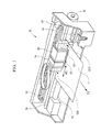
- Fig. 1 is a perspective view of an ink jet recording device usable in an image forming method according to this embodiment.
- Fig. 2 is a front view of an active radiation irradiation device illustrated in Fig. 1 .
- Fig. 3 is an arrow view along the III-III line of Fig. 2 .
- An image forming method includes: a first process for ejecting liquid droplets of a radiation curable ink composition onto a recording medium from an ejection head capable of ejecting the radiation curable ink composition using an ink jet recording device; and a second process for irradiating the liquid droplets with active radiation by an irradiation measure capable of emitting the active radiation, in which, among the liquid droplets of the radiation curable ink composition irradiated with the active radiation, a difference of the total irradiation energy of a liquid droplet having the highest total irradiation energy of the active radiation and a liquid droplet having the lowest total irradiation energy of the active radiation in the second process is 30% or more and 50% or lower of the irradiation energy (E 90 ) [mJ/cm 2 ] required for curing 90% of the radiation curable ink composition.
- E 90 irradiation energy
- the "image” refers to a print pattern formed from a dot group and also includes text printing and solid printing.
- the image forming method according to this embodiment is applied to the case of forming an image only using radiation curable ink compositions of the same formulation.
- the first process is a process for ejecting liquid droplets of a radiation curable ink composition onto a recording medium from an ejection head capable of ejecting the radiation curable ink composition using an ink jet recording device.
- FIG. 1 is a perspective view of the ink jet recording device usable in the image forming method according to this embodiment.
- An ink jet recording device 20 illustrated in Fig. 1 has a motor 30 that transports a recording medium P in a sub-scanning direction SS, a platen 40, an ejection head 52 that forms a radiation curable ink composition into liquid droplets having a very small particle size, and jetting the liquid droplets from a head nozzle so that the liquid droplets are ejected onto the recording medium P, a carriage 50 on which the ejection head 52 is mounted, a carriage motor 60 that moves the carriage 50 in a main scanning direction MS, and a pair of active radiation irradiation devices 90A and 90B that irradiate, with active radiation, the liquid droplets that are attached onto the recording medium P by ejecting the liquid droplets of the radiation curable ink composition from the ejection head 52.
- the carriage 50 is towed by a traction belt 62 that is driven by the carriage motor 60 to move along with a guide rail 64.
- the ejection head 52 is mounted on the carriage 50 and performs main scanning in which the ejection head moves in the main scanning direction MS with the operation of the carriage 50 in the moving direction (hereinafter also referred to as a "main scanning direction”) MS.
- the ejection head 52 can eject the radiation curable ink composition.
- the ejection head 52 is a serial type head for full color printing that jets 4 color inks, in which a large number of head nozzles are provided for each color.
- a black cartridge 54 as a black ink container containing a black ink to be supplied to the ejection head 52 and a color ink cartridge 56 as a color ink containing a color ink to be supplied to the ejection head 52 are mounted in addition to the ejection head 52.
- the ink contained in each of the cartridges 54 and 56 is the radiation curable ink composition described later.
- the amount of the liquid droplets ejected from the ejection head 52 in the first process of this embodiment is preferably 1 pl or more and 20 pl or lower.
- the ejection stability is favorable and a high-resolution image can be obtained.
- a capping device 80 for sealing the nozzle surface of the ejection head 52 during stopping is provided at the home position (position at the right side of Fig. 1 ) of the carriage 50.
- the capping device 80 automatically rises with a mechanism, which is not illustrated, to seal the nozzle surface of the ejection head 52.
- the capping prevents drying of the inks in the nozzles.
- the positioning control of the carriage 50 is performed for, for example, accurately positioning the carriage 50 at the position of the capping device 80.
- ink jet recording device 20 allows ejection of the liquid droplets of the radiation curable ink composition on a recording medium.
- the first process and the second process described later can be continuously performed with one device without performing the first process and the second process described later with separate devices.
- the second process is a process for irradiating the liquid droplets with the active radiation by an irradiation measure capable of emitting the active radiation.
- active radiation is emitted using the above-described ink jet recording device 20.
- Fig. 1 is a front view of the active radiation irradiation devices 90A (equivalent to 190A of Fig. 2 ) and 90B (equivalent to 190B of Fig. 2 ) illustrated in Fig. 1 .
- Fig. 3 is an arrow view along the III-III line of Fig. 2 .
- the active radiation irradiation devices 190A and 190B are individually attached to both side ends along the moving direction of the carriage 50.
- the active radiation irradiation device 190A attached to the left hand side of the ejection head 52 irradiates the liquid droplets ejected onto the recording medium P with active radiation during right scanning in which the carriage 50 moves in the right direction (direction of arrow B of Fig. 2 ).
- the active radiation irradiation device 190B attached to the right hand side of the ejection head 52 irradiates the liquid droplets ejected onto the recording medium P with active radiation during left scanning in which the carriage 50 moves in the left direction (direction of arrow C of Fig. 2 ) .
- Each of the active radiation irradiation devices 190A and 190B is attached to the carriage 50 and has a case 194 supporting one active radiation light source 192 in alignment therewith and a light source control circuit (not illustrated) that controls light on and out of the active radiation light source 192.
- the active radiation irradiation devices 190A and 190B each are provided with one active radiation light source 192 as illustrated in Figs. 2 and 3 but may be provided with two or more active radiation light sources 192.
- As the active radiation light source 192 either an LED (Light Emitting Diode) or an LD (Laser Diode) is preferably used.
- the active radiation light source As compared with the case where a mercury lamp, a metal halide lamp, and other lamps are used as the active radiation light source, an increase in the size of the active radiation light source due to the equipment of a filter and the like can be avoided. Moreover, the intensity of the active radiation emitted by the absorption with a filter does not decrease, and thus the radiation curable ink composition can be efficiently secured.
- each active radiation light source 192 the wavelength to be emitted may be the same or different.
- the wavelength of the active radiation to be emitted may be in the range of about 350 nm to about 430 nm.
- active radiation 192a is emitted to the liquid droplets, which are attached onto the recording medium P by the ejection from the ejection head 52, by the active radiation light source 192 irradiating the surface of the recording medium P near the ejection head 52 to cure at least the surface of the liquid droplets, and thus an image can be formed on the recording medium.
- the image can be formed so that the film thickness of the image formed on the recording medium is 1 ⁇ m or more and 30 ⁇ m or lower.
- the film thickness of the image formed on the recording medium is within the range mentioned above, curling of the recording medium, wrinkles of the image, and the like can be reduced, and thus a favorable image can be obtained.
- first liquid droplets are ejected onto the recording medium P while moving the carriage 50 in the right direction (direction of arrow B of Fig. 2 ), and then the first liquid droplets are irradiated with active radiation by the active radiation irradiation device 190A.
- sub-scanning in which the recording medium P is moved in the sub-scanning direction SS is performed.
- the movement distance of the recording medium P in the sub-scanning is shorter than the distance in the sub-scanning direction of nozzle rows for use in recording of the ejection head 52.
- the sub-scanning direction SS in this embodiment is orthogonal to the main scanning direction MS but is not limited thereto and is determined based on a direction in which the recording medium P is transported.
- one main scanning in which liquid droplets are ejected while moving the carriage 50 in one direction of the main scanning direction MS, and then the liquid droplets are irradiated with active radiation is referred to as 1 pass.
- the first liquid droplets on the recording medium are irradiated with active radiation by the active radiation irradiation device 190A and the active radiation irradiation device 190B.
- sub-scanning in which the recording medium P is moved in the sub-scanning direction SS is further performed.
- the first liquid droplets are irradiated with active radiation by two passes and are irradiated with active radiation 3 times in total, i.e., once in the first pass and twice in the second pass.
- the second liquid droplets are irradiated with active radiation by 1 pass and one active radiation irradiation is performed.
- an image containing a group of liquid droplets can be formed in a given region (region having a width corresponding to the distance of the nozzle rows of the ejection head 52 in the sub-scanning direction and extending in the main scanning direction) of the recording medium.
- the n-th liquid droplet ejected by the n-th pass is irradiated by 1 pass.
- the liquid droplets ejected by a nozzle positioned at the uppermost stream in the sub-scanning direction among the nozzle rows for use in recording of the ejection head 52 are the first liquid droplets and the liquid droplets ejected by a nozzle positioned at the lowest stream in the sub-scanning direction among the nozzle rows for use in recording of the ejection head 52 are the n-th liquid droplets.
- the first liquid droplets are liquid droplets in which the number of passes, in which the liquid droplets are irradiated in the image formation, is the largest and are liquid droplets in which the number of times of irradiation is the largest among the liquid droplets forming the image.
- the n-th liquid droplets are liquid droplets in which the number of passes, in which the liquid droplets are irradiated in the image formation, is the smallest and are liquid droplets in which the number of times of irradiation is the smallest.
- Each liquid droplet is cured to a degree such that dot bleeding or the occurrence of mixing of colors can be suppressed by the irradiation performed in the image formation.
- the state where the liquid droplets are cured to such a state is referred to as "semi-cured". More specifically, when the image formation is completed, the respective liquid droplets forming the image are at least semi-cured.
- the semi-curing is achieved by irradiating the liquid droplets of the radiation curable ink composition with active radiation until the curing rate of the liquid droplets is lower than 90%.
- the total irradiation energy applied to the semi-cured liquid droplets is lower than the irradiation energy (E 90 ) [mJ/cm 2 ] required for curing 90% of the radiation curable ink composition described later.
- Each liquid droplet is semi-cured by irradiation in the image formation. Thereafter, the recording medium on which the image is formed can be irradiated for further curing each liquid droplet.
- the state where the liquid droplets are cured to such a state is referred to as "completely cured".
- the completely curing is achieved by irradiating the liquid droplets of the radiation curable ink composition with active radiation in such a manner that the curing rate of the liquid droplets is 90% or more.
- the total irradiation energy applied to the liquid droplets before completely curing is equal to or higher than the irradiation energy (E 90 ) [mJ/cm 2 ] required for curing 90% of the radiation curable ink composition described later.
- E 90 irradiation energy
- the ink jet recording device 20 for use in the image forming method of this embodiment may separately have an active radiation irradiation measure (not illustrated) for completely curing at the downstream side in the sub-scanning direction SS which is the moving direction of the recording medium P.
- an active radiation irradiation measure (not illustrated) for completely curing at the downstream side in the sub-scanning direction SS which is the moving direction of the recording medium P.
- the active radiation irradiation measure for completely curing provided at the downstream side of the sub-scanning direction SS may be provided at the position where active radiation can be emitted to the liquid droplets on the recording medium P transported in the sub-scanning direction SS and, for example, can be provided at the carriage 50 and at the downstream side (the sub-scanning direction SS which is the moving direction of the recording medium P) of the ejection head 52.
- the active radiation irradiation measure for completely curing may not be provided at the carriage 50 and may be provided at the downstream side of the sub-scanning direction SS in the carriage.
- the same device as the active radiation irradiation device 190A (190B) can be used as the active radiation irradiation device 190A (190B) can be used.
- the completely curing is not limited to being carried out by the active radiation irradiation measure for completely curing provided at the downstream side of the sub-scanning direction SS and can be carried out by the active radiation irradiation device 190A and the active radiation irradiation device 190B.
- a difference of the total irradiation energy of a liquid droplet having the highest total irradiation energy of the active radiation and a liquid droplet having the lowest total irradiation energy of the active radiation among the liquid droplets of the radiation curable composition irradiated with active radiation is 30% or more and 50% or lower of the irradiation energy (E 90 ) [mJ/cm 2 ] required for curing 90% of the radiation curable ink composition.
- the total irradiation energy emitted to the liquid droplets varies for each liquid droplet depending on the number of passes, irradiation conditions, ejection timing of the liquid droplets, liquid droplet impact portions, etc.
- the first liquid droplets are irradiated with active radiation 3 times and the second liquid droplets are irradiated with active radiation once.
- the total irradiation energy emitted to the first liquid droplets becomes higher than the total irradiation energy emitted to the second liquid droplets.
- image bleeding occurs or the glossiness or the color density of the image decreases in some cases.
- the liquid droplets do not sufficiently wet and spread due to rapid curing of some liquid droplets, which sometimes results in a reduction in the glossiness of the image or a reduction in the color density of the image.
- the irradiation energy (E 90 ) [mJ/cm 2 ] required for curing 90% of the radiation curable ink composition in the invention refers to irradiation energy of active radiation required for achieving an inversion rate of 90% of a polymerizable compound in the radiation curable ink composition.
- the inversion rate can be determined from the change value of the absorbance at the peak of a specific absorption spectrum using an FT-IR (Fourier Transform-InfraRed spectroscopy) .
- the image forming method in this embodiment is excellent in that when the irradiation intensity of active radiation is set in such a manner that the difference of the total irradiation energy between liquid droplets falls in the range mentioned above in the ink jet recording device in which a required number of passes for forming a given image is set, a favorable image is easily obtained.
- the image forming method in this embodiment is also excellent in that when the number of passes is set in such a manner that the difference of the total irradiation energy between liquid droplets falls in the range mentioned above in the ink jet recording device in which the irradiation intensity of active radiation in the active radiation irradiation device is determined, a favorable image is easily obtained.
- the total irradiation energy emitted to the liquid droplets ejected onto the recording medium can be determined as follows when the ejection head 52 can move back and forth in the main scanning direction MS and the irradiation measures are provided on both sides of the ejection head 52 along the moving direction of the ejection head 52 as illustrated in Figs. 1 to 3 .
- n is an integer of 2 or more
- the number of times of irradiation of the active radiation to each of a liquid droplet having the highest total irradiation energy of the active radiation (hereinafter also referred to as "Li”) and a liquid droplet having the lowest total irradiation energy of the active radiation (hereinafter also referred to as "Lf”) is as follows.
- the number of times of irradiation of the active radiation emitted to the Li is (2n-1) times in the case of n-time passes.
- the number of times of irradiation of the active radiation emitted to the Lf is once because the active radiation is emitted from only one of the irradiation measures.
- the number of times of passes n is the number of times of passes in which each liquid droplet on the recording medium is irradiated with the active radiation, and thus there may be present n kinds of liquid droplets of from 1 to n in which the number of times of irradiation is different.
- Equation (A) the total irradiation energy emitted to the Li
- Equation (B) the total irradiation energy emitted to the Lf
- Equation (1) the range of values which E 90 can take can be represented by Equation (1).
- n 4 ⁇ n - 1 E ⁇ E 90 ⁇ 20 n - 1 E / 3 n represents an integer of 2 or more .
- Equation (1) facilitates preparation of the formulation of the radiation curable ink composition or selection of the radiation curable ink composition.
- (E 90 ) [mJ / cm 2 ] of the two or more kinds of radiation curable ink compositions for use in the image forming method of this embodiment varies depending on the formulation of the radiation curable ink compositions and is not particularly limited and is more preferably 180 [mJ/cm 2 ] or more and 250 [mJ/cm 2 ] or lower, for example.
- the radiation curable ink composition according to this embodiment contains a polymerizable compound.
- the polymerizable compound include the following monofunctional monomers, bifunctional monomers, trifunctional monomers, urethane acrylate oligomers, and amino acrylate.
- the monofunctional monomers are not particularly limited and examples include (2-methyl-2-ethyl-1,3-dioxolane-4-yl)methyl (meth) acrylate, (2-methyl 2-isobutyl-1, 3-dioxolane-4-yl) methyl (meth) acrylate, phenoxyethyl (meth) acrylate, isobornyl (meth) acrylate, methoxy diethylene glycol mono (meth) acrylate, (meth)acryloyl morpholine, dicyclopentenyloxyethyl (meth) acrylate, dicyclo pentenyl (meth) acrylate, dicyclopentanyl (meth) acrylate, isobornyl (meth) acrylate, trimethylolpropane formal mono (meth) acrylate, adamantyl (meth) acrylate, oxetane (meth) acrylate, and 3,3,5-trimethylcyclohexan
- the bifunctional monomers are not particularly limited and examples include alkylene glycol di (meth) acrylate and di (meth) acrylate having an alicyclic structure.
- alkylene glycol di (meth) acrylate examples include ethylene glycol di (meth) acrylate, diethylene glycol di (meth) acrylate, dipropyrene glycol di (meth) acrylate, tripropylene glycol di (meth) acrylate, 1, 9-nonanediol di (meth) acrylate, polyethylene glycol di (meth) acrylate, tetraethylene glycol di (meth) acrylate, 1,6-hexanediol di(meth)acrylate, neopentyl glycol di (meth) acrylate, and 2-hydroxy-1, 3-di (meth) acryloxypropane.
- di (meth) acrylate having an alicyclic structure examples include tricyclodecane dimethanol di (meth) acrylate, dioxane glycol di (meth) acrylate, isocyanuric acid EO-modified di(meth)acrylate, dimethylol tricyclodecane di (meth) acrylate, and 1,3-adamantanediol di (meth) acrylate.
- These polymerizable compounds can also be used singly or in combination of two or more kinds thereof.
- the trifunctional monomers are not particularly limited and examples include trimethylol propane tri (meth) acrylate, trimethylolpropane EO-modified tri (meth) acrylate, trimethylolpropane PO-modified tri (meth) acrylate, glycerin PO-modified tri (meth) acrylate, and isocyanuric acid EO-modified tri (meth) acrylate.
- N-vinyl compounds may be contained.
- the N-vinyl compounds include N-vinyl formamide, N-vinyl carbazole, N-vinyl acetamide, N-vinyl pyrrolidone, N-vinyl caprolactam, and derivatives thereof.
- a urethane oligomer may be contained.
- the urethane oligomer refers to one having a urethane bond and one or more radically polymerizable unsaturated double bonds in the molecules.
- the oligomer for use in this embodiment refers to molecules of intermediate relative molecular mass (synonymous with a molecular weight) having a repetition structure of a small plurality, generally about twice to about 20 times, of units substantially or conceptually derived from molecules of low relative molecular mass.
- urethane oligomer examples include oligomers produced by the addition reaction of polyol and polyisocyanate and a polyhydroxy compound.
- examples of the urethane oligomer include polyester urethane acrylate, polyether urethane acrylate, polybutadiene urethane acrylate, and polyol urethane acrylate.
- Specific examples of the urethane oligomer include CN963J75, CN964, CN965, and CN966J75 (all are available from SARTOMER) .
- aminoacrylate may be contained.
- the aminoacrylate include one obtained by reacting bifunctional (meth) acrylate and an amine compound.
- bifunctional acrylate examples include alkylene glycol di (meth) acrylates, such as propylene glycol di(meth)acrylate, 1,3-butylene glycol di (meth) acrylate, 1 , 4-butanediol di (meth) acrylate, 1,6-hexanediol di (meth) acrylate, 1, 9-nonanediol di (meth) acrylate, and neopentyl glycol di (meth) acrylate, bisphenol alkylene oxide adduct di (meth) acrylates, such as di (meth) acrylate of an ethylene oxide adduct of bisphenol S, di (meth) acrylate of an ethylene oxide adduct of bisphenol F, di(meth)acrylate of an ethylene oxide adduct of bisphenol A, di (meth) acrylate of an ethylene oxide adduct of thiobisphenol, and di (meth) acrylate of an al
- amine compound examples include monofunctional amine compounds, such as ethylamine, n-propylamine, isopropylamine, n-butylamine, isobutylamine, n-pentylamine, isopentylamine, n-hexylamine, cyclohexylamine, n-heptylamine, n-octylamine, 2-ethylhexyl amine, n-nonylamine, n-decylamine, n-dodecylamine, n-tetradecylamine, n-hexadecylamine, n-octadecylamine, benzylamine, and phenethylamine and polyfunctional amine compounds, such as diethylenetriamine, triethylenetetramine, tetraethylenepentamine, 1,6-hexamethylenediamine, 1,8-octamethylenediamine, 1,12-dode
- the content of the polymerizable compound is preferably 20% by mass or more and more preferably 20% by mass or more and 95% by mass or lower based on the total mass of the radiation curable ink composition.
- the radiation curable ink composition according to this embodiment may contain a photopolymerization initiator.
- the photopolymerization initiator is a general term of compounds having a function of initiating a copolymerization reaction of the polymerizable compound described above by irradiating the radiation curable ink composition ejected onto the recording medium with active radiation.
- the photopolymerization initiator examples include known photopolymerization initiators, such as an alkylphenone photopolymerization initiator, an acylphosphine oxide photopolymerization initiator, a titanocene photopolymerization initiator, and a thioxanthone photopolymerization initiator.
- photopolymerization initiators such as an alkylphenone photopolymerization initiator, an acylphosphine oxide photopolymerization initiator, a titanocene photopolymerization initiator, and a thioxanthone photopolymerization initiator.
- molecule cleavage types such as 2,4,6-trimethylbenzoyl-diphenylphosphine oxide having excellent compatibility with the reaction components described above and bis(2,4,6-trimethylbenzoyl)-phenylphosphine oxide having broad light absorption properties or a hydrogen abstraction type, such as diethyl thioxanthone, are preferable
- the reason for the fact that the acylphosphine oxide photopolymerization initiator is preferable resides in the fact that the absorption considerably changes because the structure of a chromophore considerably changes before and after photocleavage and a short wavelength of absorption referred to as photobleaching (photofading) is observed. Moreover, although the absorption reaches a UV region from a VL region, yellowing is hard to occur and internal curing is excellent. Therefore, the photopolymerization initiator is particularly preferable for a transparent thick film or a pigment containing coat film having high hiding power.
- the reason for the fact that the thioxanthone photopolymerization initiator is preferable resides in the fact that the thioxanthone photopolymerization initiator has an action of reacting with oxygen remaining in the reaction system after photocleavage to reduce the oxygen concentration in the system.
- the radical polymerization hindering degree can be reduced corresponding to the reduction in the oxygen concentration, and thus the surface curing properties can be improved.
- These photopolymerization initiators can also be used singly, but when used in combination of two or more kinds thereof, the properties of each photopolymerization initiator can be maximized.
- the content of the photopolymerization initiator is preferably 1% by mass or more and 20% by mass or lower and more preferably 5% by mass or more and 15% by mass or lower based on the total mass of the radiation curable ink composition.
- the radiation curable ink composition according to this embodiment can contain additives, such as pigments, dispersants, slipping agents, photosensitizers, and polymerization inhibitors, as required.
- the radiation curable ink composition according to this embodiment can function as a so-called clear ink as it is but pigments may be added thereto.
- Pigments usable in this embodiment are not particularly limited and inorganic pigments and organic pigments are mentioned.
- the inorganic pigments carbon black manufactured by known method, such as a contact method, a furnace method, and a thermal method, can be used in addition to titanium oxide and iron oxide.
- azo pigments including azo lake, insoluble azo pigments, condensed azo pigments, and chelate azo pigments
- polycyclic pigments e.g., a phthalocyanine pigment, a perylene pigment, a perynone pigment, an anthraquinone pigment, and a quinofuralone pigment
- nitro pigments nitroso pigments, and aniline black.
- C.I. pigment black 7 is mentioned as carbon black.
- Examples include No. 2300, No. 900, MCF88, No. 33, No. 40, No. 45, No. 52, MA7, MA8, MA100, No.
- pigments usable when forming the radiation curable ink composition according to this embodiment into a yellow ink include C.I. Pigment Yellow 1, 2, 3, 12, 13, 14, 16, 17, 73, 74, 75, 83, 93, 95, 97, 98, 109, 110, 114, 120, 128, 129, 138, 150, 151, 154, 155, 180 185, and 213.
- pigments usable when forming the radiation curable ink composition according to this embodiment into a magenta ink include C.I. Pigment Red 5, 7, 12, 48 (Ca), 48(Mn), 57(Ca), 57: 1, 112, 122, 123, 168, 184, 202 and 209 and C.I. Pigment violet 19.
- pigments usable when forming the radiation curable ink composition according to this embodiment into a cyan ink include C.I. Pigment Blue 1, 2, 3, 15:3, 15:4, 16, 22, and 60.
- pigments usable when forming the radiation curable ink composition according to this embodiment into a green ink include C.I. Pigment green 7, 8, and 36.
- pigments usable when forming the radiation curable ink composition according to this embodiment into an orange ink include C.I. Pigment orange 51 and 66.
- pigments usable when forming the radiation curable ink composition according to this embodiment into a white ink include basic lead carbonate, zinc oxide, titanium oxide, and strontium titanate.
- the average particle size of the pigments usable in this embodiment is preferably in the range of 10 nm or more and 200 nm or lower and more preferably in the range of 50 nm or more and 150 nm or lower.
- the addition amount of the pigments that can be added to the radiation curable ink composition according to this embodiment is 0.1% by mass or more and 25% by mass or lower and more preferably 0.5% by mass or more and 15% by mass or lower based on the total mass of the radiation curable ink composition.
- dispersants may be added in order to increase the dispersibility of the pigments described above.
- the dispersants usable in this embodiment include high molecular weight dispersants, such as Solsperse3000, 5000, 9000, 12000, 13240, 17000, 24000, 26000, 28000, and 36000 (all manufactured by Lubrizol Corporation) and DISCOALL N-503, N-506, N-509, N-512, N-515, N-518, and N-520 (all manufactured by DAI-ICHI KOGYO SEIYAKU Co., Ltd.).
- the slipping agent usable in this embodiment is preferably a silicone surfactant and more preferably polyester-modified silicone or polyether-modified silicone.
- polyester-modified silicone examples include BYK-347, BYK-348, BYK-UV3500, BYK-UV3510, and BYK-UV3530 (all manufactured by BYK-Chemie Japan K.K.).
- polyether-modified silicone examples include BYK-3570 (manufactured by BYK-Chemie Japan K.K.).
- a photosensitizer may be added to the radiation curable ink composition according to this embodiment.
- the photosensitizer usable in this embodiment include amine compounds (e.g., aliphatic amine, amine containing an aromatic group, piperidine, a reaction product of epoxy resin and amine, and triethanolamine triacrylate), urea compounds (e.g., allyl thiourea and o-tolylthiourea), sulfur compounds (e.g., sodium diethyl dithiophosphate and soluble salt of aromatic sulfinic acid), nitrile compounds (e.g., N,N-diethyl-p-aminobenzanitrile), phosphorus compounds (tri-n-butylphosphine and sodium diethyl dithiophosphide), nitrogen compounds (e.g., Michler's ketone, an N-nitrosohydroxylamine derivative, an oxazolidine compound, a tetrahydro-1,3-o
- a polymerization inhibitor may be added to the radiation curable ink composition according to this embodiment.
- the polymerization inhibitor usable in this embodiment include hydroquinone, benzoquinone, and p-methoxyphenol.
- the viscosity at 20°C of the radiation curable ink composition according to this embodiment is preferably 5 mPa ⁇ s or more and 50 mPa ⁇ s or lower and more preferably 20 mPa ⁇ s or more and 40 mPa ⁇ s or lower.
- a proper amount of the radiation curable ink composition is ejected from a nozzle and curved flight or scattering of the radiation curable ink composition can be further reduced.
- the radiation curable ink composition can be preferably used for ink jet recording devices.
- the viscosity is measured as follows. The Shear Rate is increased to 10 to 1000 under a 20°C environment, and then the viscosity at a Shear Rate of 200 is read using a viscoelasticity testing machine MCR-300 (manufactured by Pysica) .
- the surface tension at 20°C of the radiation curable ink composition according to this embodiment is preferably 20. mN/m or more and 30 mN/m or lower.
- the radiation curable ink composition is hard to wet to a nozzle subjected to liquid repellent treatment.
- a proper amount of the radiation curable ink composition is ejected from a nozzle and curved flight or scattering of the radiation curable ink composition can be further reduced. Therefore, the radiation curable ink composition can be preferably used in ink jet recording devices.
- the surface tension is measured by confirming the surface tension when a platinum plate is soaked in ink under a 20°C environment using an automatic surface tension meter CBVP-Z (manufactured by Kyowa Interface Science Co., LTD. ) .
- a recording medium for use in the image forming method according to this embodiment is preferably a non-ink absorbing or low-ink absorbing recording medium.
- a favorable image can be formed even when the recording medium is a non-ink absorbing or low-ink absorbing recording medium.
- non-ink absorbing recording medium examples include one in which plastics are coated on a base material, such as a plastic film or paper that has not been surface treated for ink jet printing (i.e., an ink absorption layer is not formed) and one in which a plastic film has been attached thereto.
- plastics mentioned here include polyvinyl chloride, polyethylene terephthalate, polycarbonate, polystyrene, polyurethane, polyethylene, and polypropylene.
- low-ink absorbing recording medium examples include printing paper, such as art paper, coat paper, and mat paper.
- the "non-ink absorbing or low-ink absorbing recording medium” in this description refers to a "recording medium in which the water absorption amount from the initiation of contact to 30 msec l/2 is 10 mL /M 2 or lower in the Bristow method".
- This Bristow method is the most spread method as a method for measuring the liquid absorption amount in a short time and is employed also in the Japan Technical Association of the Pulp and Paper Industry (JAPAN TAPPI). The details of a test method are described in "Liquid Absorbency Test Method of Paper and Paperboard (Bristow Method) of No. 51 of "JAPAN TAPPI paper pulp test method, 2000".
- the non-ink absorbing or low-ink absorbing recording medium is also referred to as "plastic media”.
- An image forming method includes: a first process for ejecting liquid droplets of two or more kinds of radiation curable ink compositions onto a recording medium from an ejection head capable of ejecting the radiation curable ink compositions using an ink jet recording device; and a second process for irradiating the liquid droplets with active radiation by an irradiation measure capable of ejecting the active radiation, in which, in the two or more kinds of radiation curable ink compositions, a difference of the total irradiation energy of a liquid droplet having the highest total irradiation energy of the active radiation and a liquid droplet having the lowest total irradiation energy of the active radiation among liquid droplets of the same kind of the radiation curable ink compositions irradiated with the active radiation in the second process is 30% or more and 50% or lower of the irradiation energy (E 90 ) [mJ/cm 2 ] required for curing 90% of the radiation curable ink compositions.
- E 90 irradi
- the image forming method according to the second embodiment is different from the image forming method according to the first embodiment in that the liquid droplets of two or more kinds of radiation curable ink compositions are ejected onto a recording medium. More specifically, the image forming method according to the second embodiment can be used for so-called color printing using two or more colors of radiation curable ink compositions.
- the ejection head in this embodiment ejects liquid droplets of two or more kinds of radiation curable ink compositions onto a recording medium.
- radiation curable ink compositions in which the contained materials are different for each radiation curable ink composition may be used or radiation curable ink compositions in which the contained materials are the same for each radiation curable ink composition and the formulation ratios are different may be used.
- two or more colors of liquid droplets in which the hue is different from each other are ejected onto a recording medium.
- the image forming method according to the second embodiment is excellent in that, in the ink jet recording device in which a required number of passes for forming a given image is set, when the irradiation intensity of the active radiation is set in such a manner that the irradiation energy between the same kind of liquid droplets fall in the range mentioned above, a favorable image is easily obtained even when the liquid droplets of the two or more kinds of radiation curable ink compositions are ejected onto a recording medium.
- the image forming method according to the second embodiment is excellent in that, in the ink jet recording device in which the irradiation intensity of the active radiation in the active radiation irradiation devices is determined, when the number of passes is set in such a manner that a difference in the total irradiation energy between the same kind of liquid droplets falls in the range mentioned above, a favorable image is easily obtained even when the liquid droplets of the two or more kinds of radiation curable ink compositions are ejected onto a recording medium.
- Equation (1) (E 90 ) [mJ/cm 2 ] of the two or more kinds of radiation curable ink compositions for use in the image forming method of this embodiment can satisfy Equation (1).
- n represents an integer of 2 or more .
- Equation (1) facilitates preparation of the formulation of the radiation curable ink composition or selection of the radiation curable ink composition.
- (E 90 ) [mJ/cm 2 ] of the two or more kinds of radiation curable ink compositions for use in the image forming method of this embodiment varies depending on the formulation of the radiation curable ink compositions and is not particularly limited and is more preferably 180 [mJ/cm 2 ] or more and 250 [mJ/cm 2 ] or lower, for example.
- the irradiation conditions of the active radiation suitable for all the liquid droplets are easily determined even when the liquid droplets of the two or more kinds of radiation curable ink compositions are ejected onto a recording medium.
- a difference ( ⁇ E 90 ) of (E 90 ) [mJ/cm 2 ] between the two or more kinds of radiation curable ink compositions can be represented by Equation (2) using Equation (1) above.
- n represents an integer of 2 or more .
- the radiation curable ink compositions are sometimes different in the total irradiation energy required for curing depending on the contained materials. Therefore, when the irradiation energy per irradiation carried out by the irradiation measures E[mJ/cm 2 ] and the number of passes n for forming a given image are determined, the irradiation conditions of the active radiation suitable for all the liquid droplets can be easily determined and a favorable image can be obtained even when the liquid droplets of the two or more kinds of radiation curable ink compositions are ejected onto the recording medium.
- the difference ( ⁇ E 90 ) of (E 90 ) [mJ/cm 2 ] between the two or more kinds of radiation curable ink compositions for use in the image forming method of this embodiment is more preferably within 70 [mJ/cm 2 ].
- An ink jet recording device has; an ejection head that ejects liquid droplets of a radiation curable ink composition onto a recording medium; and an active radiation irradiation device that irradiates the liquid droplets with active radiation, in which the ink jet recording device has a control measure for controlling a difference of the total irradiation energy of a liquid droplet having the highest total irradiation energy of the active radiation and a liquid droplet having the lowest total irradiation energy of the active radiation among the liquid droplets of the radiation curable ink composition irradiated with the active radiation to 30% or more and 50% or lower of the irradiation energy (E 90 ) [mJ/cm 2 ] required for curing 90% of the radiation curable ink composition.
- E 90 irradiation energy
- the ink jet recording device 20 described in the first embodiment can be used, for example.
- the ink jet recording device in this embodiment will be described with reference to the ink jet recording device 20 described above and the description of the same components and the same functions as those in the first embodiment is omitted.
- the ink jet recording device has a control measure.
- a control circuit (not illustrated) mounted on the ink jet recording device 20 can be used.
- the control circuit controls the difference of the total irradiation energy of a liquid droplet having the highest total irradiation energy of the active radiation and a liquid droplet having the lowest total irradiation energy of the active radiation to be 30% or more and 50% or lower of the irradiation energy (E 90 ) [mJ/cm 2 ] required for curing 90% of the radiation curable ink composition.
- control circuit can control the number of passes for forming a given image when the irradiation energy emitted from the active radiation irradiation device 90A (90B) is set beforehand.
- the irradiation energy of the active radiation irradiation device 90A (90B) can be controlled and light on and out of the active radiation irradiation device 90A (90B) can be controlled using the above-described light source control circuit (not illustrated).
- the difference of the total irradiation energy of a liquid droplet having the highest total irradiation energy of the active radiation and a liquid droplet having the lowest total irradiation energy of the active radiation is controlled to be 30% or more and 50% or lower of the irradiation energy (E 90 ) [mJ/cm 2 ] required for curing 90% of the radiation curable ink composition. Therefore, the ink jet recording device 20 according to this embodiment can record an image in which the glossiness is excellent, image bleeding can be reduced, and the color density is high.
- the ink jet recording device described in the second embodiment may be used in the third embodiment.
- the ink jet recording device described in the second embodiment may be used in the third embodiment.
- the number of passes or controlling the irradiation energy of the active radiation irradiation device 90A (90B) in such a manner that the difference ( ⁇ E 90 ) of E 90 between the two or more kinds of radiation curable ink compositions satisfies the relationship of Equation (2) above in addition to the above description an image in which the glossiness is excellent, image bleeding can be reduced, and the color density is high can be recorded.
- a recorded material according to one embodiment of the invention is recorded by the image forming method described above. Since the image recorded on the recording medium is recorded by the image forming method described above, bleeding hardly occurs, the image glossiness is excellent, and the color density is high.
- the image is formed by so-called bidirectional image formation in which the image is formed by main scanning in which the ejection head 52, having light sources (190A, 190b) on both sides in a given direction, moves back and forth in both directions along the given direction.
- the image formation method is not limited to the above and so-called single direction image formation in which the image is formed by ejecting liquid droplets by main scanning of the ejection head 52, having a light source at only one side in the given direction, in one direction (direction opposite to the one side) in the given direction may be performed.
- Phenoxyethyl acrylate (manufactured by Osaka Organic Chemical Industry, LTD., Trade name "V#192") as a monofunctional monomer was added to 18 parts by mass of a black pigment (manufactured by Ciba Specialty Chemicals Inc., Trade name .”MICROLITH-WA Black C-WA”) as a colorant and 1.2 parts by mass of Solsperse36000 (manufactured by LUBRIZOL) as a dispersant to be 100 parts by mass in total, and then mixed and stirred to obtain a mixture.
- a black pigment manufactured by Ciba Specialty Chemicals Inc., Trade name .”
- Solsperse36000 (manufactured by LUBRIZOL) as a dispersant to be 100 parts by mass in total, and then mixed and stirred to obtain a mixture.
- the mixture was dispersed with zirconia beads (1.5 mm in diameter) for 6 hours using a sand mill l (manufactured by Yasukawa Seisakusho K.K. ) . Thereafter, the zirconia beads were separated with a separator, thereby obtaining a black pigment dispersion liquid. Similarly, a cyan pigment dispersion liquid, a magenta pigment dispersion liquid, and a yellow pigment dispersion liquid were obtained.
- Polymerizable compounds, photopolymerization initiators, slipping agents, and polymerization inhibitors were mixed and completely dissolved in such a manner as to achieve the formulations (% by mass) shown in Table 1. Thereafter, the black pigment dispersion liquid was added dropwise under stirring in such a manner that the concentration of the black pigment becomes the concentration shown in Table 1. After the completion of dropwise addition, the mixture was mixed and stirred at room temperature for 1 hour, and then filtered with a 5 ⁇ m membrane filter, thereby obtaining a black radiation curable ink composition. Similarly, a cyan radiation curable ink composition, a magenta radiation curable ink composition, and a yellow radiation curable ink composition were obtained.
- the irradiation energy (E 90 ) [mJ/cm 2 ] of active radiation required for curing 90% of a radiation curable ink composition was measured using FT-IR (manufactured by Thermo Fisher Scientific K.K., Trade name "MAGNA-IR 860 Nicolet”) from the peak (810 cm -1 ) of the absorption spectrum of a vinyl group of each radiation curable ink composition before and after irradiation of active radiation.
- the peak height A o at 810 cm -1 before irradiation and the peak height At at 810 cm -1 after irradiation were determined from the IR spectrum, and the curing rate was calculated using Equation (3).
- Curing rate % 100 ⁇ 1 - A t / A o
- the E 90 value of each of the obtained radiation curable ink compositions is shown in Table 1.
- the measurement of the irradiation energy of the radiation curable ink compositions was performed in a state where the distance from a UV-LED (same as one used in Example described later) to the radiation curable ink composition was made the same as the distance from a UV-LED in a ultraviolet irradiation device in Example described later to a recording medium. Then, the radiation curable ink composition was irradiated with the above-described UV-LED with an active peak wavelength of 395 nm, and the irradiation energy of the radiation curable ink composition was measured.
- the irradiation energy [mJ/cm 2 ] was measured from the product of the irradiation intensity [mW/cm 2 ] on the irradiated surface irradiated by the UV-LED, which was separately measured, and the irradiation duration time [s].
- the measurement of the irradiation intensity was performed by a ultraviolet ray intensity meter UM-10 and a light receiving portion UM-400 (manufactured by Konica Minolta Sensing, Inc.).
- the radiation curable ink compositions were charged for each color in each nozzle row using an ink jet printer PX-G5000 (manufactured by Seiko Epson Corporation).
- liquid droplets were ejected onto a PET film under room temperature and normal pressure so that each color of cyan (C), magenta (M) , yellow ( Y ) , and black (K) contacted and the liquid droplets were irradiated with 395 nm ultraviolet rays of an irradiation intensity in the range of 2 mW/cm 2 to 39 mW/cm 2 from UV-LEDS in ultraviolet irradiation devices mounted on both sides of a carriage, and then the PET film was transported in the sub-scanning direction.
- Such operation was performed 5 times (5 passes) to thereby form a solid pattern image on the PET film. Then, ultraviolet rays were emitted to the entire solid pattern image so that the total quantity of light was 400 mJ/cm 2 or more to perform curing treatment for completely curing the solid pattern image.
- the printing conditions were as follows: Resolution of 720 x 720 dpi and Liquid droplet amount of 14 pl.
- the radiation curable ink compositions were charged for each color in each nozzle row using an ink jet printer PX-G5000 (manufactured by Seiko Epson Corporation).
- liquid droplets were ejected onto a PET film under room temperature and normal pressure so that each color of CMYK contacted and the liquid droplets were irradiated with 395 nm ultraviolet rays of an irradiation intensity of 6 mW/cm 2 from UV-LEDs in ultraviolet irradiation devices mounted on both sides of a carriage, and then the PET film was transported in the sub-scanning direction.
- Such operation was performed two or more times (two or more passes) to thereby form a solid pattern image on the PET film. Then, ultraviolet rays were emitted to the entire solid pattern image so that the total quantity of light was 400 mJ/cm 2 or more to perform curing treatment for completely curing the solid pattern image.
- the printing conditions were as follows: Resolution of 720 x 720 dpi and Liquid droplet amount of 14 pl.
- the obtained recorded materials were observed and evaluated bleeding in the contact portion with other colors for each color for.
- the evaluation criteria are classified as follows. A: No bleeding to other colors is observed. B: Bleeding to other color is slightly observed. C: Bleeding to other colors is observed.
- the radiation curable ink compositions were charged for each color in each nozzle row using an ink jet printer PX-G5000 (manufactured by Seiko Epson Corporation).
- liquid droplets were ejected onto a PET film under room temperature and normal pressure and the liquid droplets were irradiated with 395 nm ultraviolet rays of an irradiation intensity in the range of 1.5 mW/cm 2 to 39 mW/cm 2 from UV-LEDs in ultraviolet irradiation devices mounted on both sides of a carriage, and then the PET film was transported in the sub-scanning direction.
- Such operation was performed 5 times (five pass) to thereby form a solid pattern image of a single color on the PET film. Then, ultraviolet rays were emitted to the entire solid pattern image so that the total quantity of light was 400 mJ/cm 2 or more to perform curing treatment for completely curing the solid pattern images.
- the printing conditions were as follows: Resolution of 720 x 720 dpi and Liquid droplet amount of 14 pl.
- the radiation curable ink compositions were charged for each color in each nozzle row using an ink jet printer PX-G5000 (manufactured by Seiko Epson Corporation).
- liquid droplets were ejected onto a PET film under room temperature and normal pressure and the liquid droplets were irradiated with 395 nm ultraviolet rays of an irradiation intensity of 6 mW/cm 2 from UV-LEDs in ultraviolet irradiation devices mounted on both sides of a carriage, and then the PET film was transported in the sub-scanning direction.
- Such operation was performed two or more times (two or more passes) to thereby form a solid pattern image on the PET film. Then, ultraviolet rays were emitted to the entire solid pattern image so that the total quantity of light was 400 mJ/cm 2 or more to perform curing treatment for completely curing the solid pattern image.
- the printing conditions were as follows: Resolution of 720 x 720 dpi and Liquid droplet amount of 14 pl.
- the specular gloss at 60° of the obtained image was measured using a gloss meter MULTI Gloss 268 (manufactured by Konica Minolta Co., Ltd. ) based on JIS Z8741.
- the evaluation criteria of the glossiness of the obtained image are as follows, and gloss is accepted in the image evaluated as B or higher.
- 0D value of 1.8 or more Color density is high and color development is good.
- OD value of lower than 1.8 Color density is low and color development is poor.
- the evaluation results were shown in Tables 2 to 7.
- the recorded materials of Tables 2 to 4 were produced in a state where the number of passes was fixed to 5 passes and the irradiation intensity of UV emitted from the ultraviolet irradiation devices was changed.
- the recorded materials of Tables 5 to 7 were produced in a state where the irradiation intensity of the ultraviolet irradiation devices was fixed to 6 mJ/cm 2 and the number of passes was changed.
- Ei represents the total irradiation energy (mJ/cm 2 ) of a liquid droplet with the highest total irradiation energy of UV emitted from the UV-LEDs in the ultraviolet irradiation devices mounted on both sides of the carriage.
- Ef represents the total irradiation energy (mJ/cm 2 ) of a liquid droplet with the lowest total irradiation energy of UV emitted from the UV-LEDs in the ultraviolet irradiation devices mounted on both sides of the carriage.
- Example 1 Example 2
- Example 3 Example 4
- Example 5 Example 5
- Example 6 Example 7
- Example 8 Example 9
- Example 10 Radiation curable ink composition type K K K C C M M Y Y Y Ei (mJ/cm 2 ) 126 108 90 108 90 90 63 126 108 90 Ef(mJ/cm 2 ) 14 12 10 12 10 10 7 14 12 10 (Ei-Ef)/E 90 (%) 45 38 32 48 40 44 31 50 43
- Evaluation results Bleeding O O O O O O O O O O O Gloss B A A B B B B B A A Color density 1.93 2.01 1.94 1.84 1.84 1.82 1.81 1.91 1.96 2.01 Table 5
- Example 11 Example 12
- Example 13 Example 14
- Example 15 Example 16
- Example 17 Example 18
- Example 19 Example 20
- Example 21 Example 22
- Example 23 Example 24
- Example 25 Radiation curable ink composition type Number of passes (pass) K K K K K C C C C M M M M M Y
- the evaluation results of Table 2 showed that, by setting the irradiation intensity of the irradiation device so that the difference between Ei and Ef is a value of 30% or more and 50% or lower of E 90 in the device in which the number of passes is fixed when forming a given image, recorded materials having favorable images are obtained.
- the evaluation results of Table 5 showed that, by setting the number of passes so that the difference between Ei and Ef is a value of 30% or more and 50% or lower of E 90 when the irradiation intensity of the radiation irradiation device was set beforehand, recorded materials having favorable images are obtained.
- the recorded materials of Examples 3, 5, 6, and 10 of Table 2 were produced in a state where the irradiation intensity of the ultraviolet irradiation devices was made the same and have favorable images. Thus, it was shown that even when different irradiation intensities are not set for each of two or more radiation curable ink compositions, the irradiation intensity with which all the radiation curable ink compositions can commonly form favorable images can be set.
Landscapes
- Health & Medical Sciences (AREA)
- General Health & Medical Sciences (AREA)
- Toxicology (AREA)
- Ink Jet (AREA)
- Ink Jet Recording Methods And Recording Media Thereof (AREA)
- Inks, Pencil-Leads, Or Crayons (AREA)
Applications Claiming Priority (2)
| Application Number | Priority Date | Filing Date | Title |
|---|---|---|---|
| JP2010077775 | 2010-03-30 | ||
| JP2010198048A JP5804235B2 (ja) | 2010-03-30 | 2010-09-03 | 画像形成方法およびインクジェット記録装置 |
Publications (3)
| Publication Number | Publication Date |
|---|---|
| EP2371565A2 true EP2371565A2 (fr) | 2011-10-05 |
| EP2371565A3 EP2371565A3 (fr) | 2013-01-02 |
| EP2371565B1 EP2371565B1 (fr) | 2014-03-12 |
Family
ID=44262784
Family Applications (1)
| Application Number | Title | Priority Date | Filing Date |
|---|---|---|---|
| EP20110160185 Not-in-force EP2371565B1 (fr) | 2010-03-30 | 2011-03-29 | Procédé de formation d'image et dispositif d'enregistrement à jet d'encre |
Country Status (4)
| Country | Link |
|---|---|
| US (1) | US8616670B2 (fr) |
| EP (1) | EP2371565B1 (fr) |
| JP (1) | JP5804235B2 (fr) |
| CN (1) | CN102218911B (fr) |
Families Citing this family (5)
| Publication number | Priority date | Publication date | Assignee | Title |
|---|---|---|---|---|
| CN104220465A (zh) * | 2012-03-22 | 2014-12-17 | 日立化成株式会社 | 光固化性树脂组合物、图像显示装置及其制造方法 |
| DE102012008641A1 (de) * | 2012-05-02 | 2013-11-07 | Heraeus Noblelight Gmbh | Leuchte mit Reflektor |
| JP6318473B2 (ja) * | 2013-06-07 | 2018-05-09 | セイコーエプソン株式会社 | インクジェット記録方法 |
| JP2018187854A (ja) * | 2017-05-09 | 2018-11-29 | セイコーエプソン株式会社 | 液滴吐出装置 |
| JP6841783B2 (ja) * | 2018-03-28 | 2021-03-10 | セイコーエプソン株式会社 | インクジェット記録方法 |
Citations (3)
| Publication number | Priority date | Publication date | Assignee | Title |
|---|---|---|---|---|
| JP2003211651A (ja) | 2002-01-24 | 2003-07-29 | Konica Corp | インクジェット記録方法、インクジェット記録装置 |
| JP2007276248A (ja) | 2006-04-06 | 2007-10-25 | Canon Inc | 活性エネルギー線硬化型インクジェット記録方法 |
| JP4147943B2 (ja) | 2003-01-14 | 2008-09-10 | コニカミノルタホールディングス株式会社 | 画像形成方法及びインクジェット記録装置 |
Family Cites Families (21)
| Publication number | Priority date | Publication date | Assignee | Title |
|---|---|---|---|---|
| US6312123B1 (en) * | 1998-05-01 | 2001-11-06 | L&P Property Management Company | Method and apparatus for UV ink jet printing on fabric and combination printing and quilting thereby |
| US7073901B2 (en) * | 2001-04-13 | 2006-07-11 | Electronics For Imaging, Inc. | Radiation treatment for ink jet fluids |
| JP2003213185A (ja) * | 2002-01-28 | 2003-07-30 | Canon Inc | インクジェット記録用インクセット及びこれを用いるインクジェット記録方法 |
| JP4724999B2 (ja) | 2002-12-13 | 2011-07-13 | コニカミノルタホールディングス株式会社 | インクジェット記録装置及びインクジェット記録方法 |
| CN100564461C (zh) * | 2004-03-26 | 2009-12-02 | 佳能株式会社 | 活性能量射线固化型水性油墨组合物、使用该组合物的喷墨记录方法、墨盒、记录单元和喷墨记录装置 |
| JP4529522B2 (ja) * | 2004-04-07 | 2010-08-25 | コニカミノルタエムジー株式会社 | インクジェット記録装置 |
| JPWO2006006598A1 (ja) * | 2004-07-13 | 2008-04-24 | 株式会社きもと | オフセット印刷版の製版方法 |
| WO2006087949A1 (fr) * | 2005-02-18 | 2006-08-24 | Konica Minolta Medical & Graphic, Inc. | Dispositif d’enregistrement à jet d’encre et procédé d’enregistrement à jet d’encre |
| JP2007062028A (ja) * | 2005-08-29 | 2007-03-15 | Konica Minolta Medical & Graphic Inc | インクジェット記録方法とインクジェット記録用インク |
| US7766440B2 (en) * | 2005-09-13 | 2010-08-03 | Fujifilm Corporation | Image forming apparatus and method |
| JP2007136707A (ja) * | 2005-11-15 | 2007-06-07 | Konica Minolta Holdings Inc | インクジェット記録方法 |
| JP2007152658A (ja) * | 2005-12-02 | 2007-06-21 | Konica Minolta Holdings Inc | インクジェット記録方法 |
| JP4251330B2 (ja) * | 2005-12-22 | 2009-04-08 | カシオ計算機株式会社 | 表示装置の製造装置及び表示装置の製造方法 |
| JP2008075019A (ja) * | 2006-09-22 | 2008-04-03 | Fujifilm Corp | 硬化性組成物、インク組成物、インクジェット記録方法、印刷物、平版印刷版の製造方法、及び平版印刷版 |
| JP5324800B2 (ja) * | 2008-02-29 | 2013-10-23 | 株式会社ミマキエンジニアリング | インクジェットプリンタ |
| JP5128312B2 (ja) * | 2008-02-29 | 2013-01-23 | 株式会社ミマキエンジニアリング | 紫外線硬化型インクジェットプリンタ、紫外線硬化型インクジェットプリンタの印刷方法及びヘッドユニット構造 |
| JP5139843B2 (ja) * | 2008-02-29 | 2013-02-06 | 株式会社ミマキエンジニアリング | インクジェットプリンタ及び印刷方法 |
| JP2009262524A (ja) * | 2008-03-31 | 2009-11-12 | Fujifilm Corp | インクジェット記録装置 |
| JP5187000B2 (ja) * | 2008-05-27 | 2013-04-24 | コニカミノルタホールディングス株式会社 | インクジェット記録装置及びインクジェット記録方法 |
| EP2340937B1 (fr) * | 2008-08-21 | 2018-09-26 | Roland DG Corporation | Dispositif d'enregistrement du type à jet d'encre et programme informatique |
| JP5047918B2 (ja) * | 2008-10-01 | 2012-10-10 | 株式会社ミマキエンジニアリング | インクジェットプリンタおよびそれを用いた印刷方法 |
-
2010
- 2010-09-03 JP JP2010198048A patent/JP5804235B2/ja not_active Expired - Fee Related
-
2011
- 2011-03-29 US US13/074,152 patent/US8616670B2/en not_active Expired - Fee Related
- 2011-03-29 EP EP20110160185 patent/EP2371565B1/fr not_active Not-in-force
- 2011-03-30 CN CN201110083630.6A patent/CN102218911B/zh not_active Expired - Fee Related
Patent Citations (3)
| Publication number | Priority date | Publication date | Assignee | Title |
|---|---|---|---|---|
| JP2003211651A (ja) | 2002-01-24 | 2003-07-29 | Konica Corp | インクジェット記録方法、インクジェット記録装置 |
| JP4147943B2 (ja) | 2003-01-14 | 2008-09-10 | コニカミノルタホールディングス株式会社 | 画像形成方法及びインクジェット記録装置 |
| JP2007276248A (ja) | 2006-04-06 | 2007-10-25 | Canon Inc | 活性エネルギー線硬化型インクジェット記録方法 |
Also Published As
| Publication number | Publication date |
|---|---|
| CN102218911A (zh) | 2011-10-19 |
| EP2371565B1 (fr) | 2014-03-12 |
| US20110242183A1 (en) | 2011-10-06 |
| EP2371565A3 (fr) | 2013-01-02 |
| JP5804235B2 (ja) | 2015-11-04 |
| CN102218911B (zh) | 2016-06-22 |
| JP2011224960A (ja) | 2011-11-10 |
| US8616670B2 (en) | 2013-12-31 |
Similar Documents
| Publication | Publication Date | Title |
|---|---|---|
| US10029485B2 (en) | Ink jet recording method | |
| US8556404B2 (en) | Photocurable ink composition for ink jet recording, ink jet recording method, and recorded material | |
| CN102585596B (zh) | 紫外线固化型喷墨用油墨组合物、使用其的喷墨记录装置、喷墨记录方法、以及油墨组 | |
| JP5664841B2 (ja) | 光硬化型インク組成物およびインクジェット記録方法 | |
| US8901200B2 (en) | Radiation-curable ink composition, ink jet recording process, and recorded matter | |
| JP2011116814A (ja) | 放射線硬化型インク組成物、ならびにインクジェット記録方法および記録物 | |
| JP5920449B2 (ja) | 液滴吐出装置の制御方法、液滴吐出装置およびインクセット | |
| EP2371565B1 (fr) | Procédé de formation d'image et dispositif d'enregistrement à jet d'encre | |
| CN111546774A (zh) | 喷墨方法、喷墨装置、喷墨头以及喷墨用组件 | |
| JP2011195649A (ja) | 光硬化型インク組成物、ならびにインクジェット記録方法および記録物 | |
| JP5750950B2 (ja) | 液滴吐出装置の制御方法、液滴吐出装置およびインクセット | |
| JP2015057330A (ja) | インクジェット記録装置及びインクジェット記録方法 | |
| JP2012016870A (ja) | 印刷装置及び印刷方法 | |
| JP2015083697A (ja) | 放射線硬化型インク組成物、ならびにインクジェット記録方法および記録物 |
Legal Events
| Date | Code | Title | Description |
|---|---|---|---|
| PUAI | Public reference made under article 153(3) epc to a published international application that has entered the european phase |
Free format text: ORIGINAL CODE: 0009012 |
|
| AK | Designated contracting states |
Kind code of ref document: A2 Designated state(s): AL AT BE BG CH CY CZ DE DK EE ES FI FR GB GR HR HU IE IS IT LI LT LU LV MC MK MT NL NO PL PT RO RS SE SI SK SM TR |
|
| AX | Request for extension of the european patent |
Extension state: BA ME |
|
| PUAL | Search report despatched |
Free format text: ORIGINAL CODE: 0009013 |
|
| AK | Designated contracting states |
Kind code of ref document: A3 Designated state(s): AL AT BE BG CH CY CZ DE DK EE ES FI FR GB GR HR HU IE IS IT LI LT LU LV MC MK MT NL NO PL PT RO RS SE SI SK SM TR |
|
| AX | Request for extension of the european patent |
Extension state: BA ME |
|
| RIC1 | Information provided on ipc code assigned before grant |
Ipc: B41M 7/00 20060101ALI20121127BHEP Ipc: B41J 11/00 20060101AFI20121127BHEP |
|
| 17P | Request for examination filed |
Effective date: 20130620 |
|
| RBV | Designated contracting states (corrected) |
Designated state(s): AL AT BE BG CH CY CZ DE DK EE ES FI FR GB GR HR HU IE IS IT LI LT LU LV MC MK MT NL NO PL PT RO RS SE SI SK SM TR |
|
| GRAP | Despatch of communication of intention to grant a patent |
Free format text: ORIGINAL CODE: EPIDOSNIGR1 |
|
| INTG | Intention to grant announced |
Effective date: 20131008 |
|
| GRAS | Grant fee paid |
Free format text: ORIGINAL CODE: EPIDOSNIGR3 |
|
| GRAA | (expected) grant |
Free format text: ORIGINAL CODE: 0009210 |
|
| AK | Designated contracting states |
Kind code of ref document: B1 Designated state(s): AL AT BE BG CH CY CZ DE DK EE ES FI FR GB GR HR HU IE IS IT LI LT LU LV MC MK MT NL NO PL PT RO RS SE SI SK SM TR |
|
| REG | Reference to a national code |
Ref country code: GB Ref legal event code: FG4D |
|
| REG | Reference to a national code |
Ref country code: CH Ref legal event code: EP |
|
| REG | Reference to a national code |
Ref country code: AT Ref legal event code: REF Ref document number: 656002 Country of ref document: AT Kind code of ref document: T Effective date: 20140315 |
|
| REG | Reference to a national code |
Ref country code: IE Ref legal event code: FG4D |
|
| REG | Reference to a national code |
Ref country code: DE Ref legal event code: R096 Ref document number: 602011005329 Country of ref document: DE Effective date: 20140424 |
|
| REG | Reference to a national code |
Ref country code: NL Ref legal event code: VDEP Effective date: 20140312 |
|
| PG25 | Lapsed in a contracting state [announced via postgrant information from national office to epo] |
Ref country code: NO Free format text: LAPSE BECAUSE OF FAILURE TO SUBMIT A TRANSLATION OF THE DESCRIPTION OR TO PAY THE FEE WITHIN THE PRESCRIBED TIME-LIMIT Effective date: 20140612 Ref country code: LT Free format text: LAPSE BECAUSE OF FAILURE TO SUBMIT A TRANSLATION OF THE DESCRIPTION OR TO PAY THE FEE WITHIN THE PRESCRIBED TIME-LIMIT Effective date: 20140312 |
|
| REG | Reference to a national code |
Ref country code: AT Ref legal event code: MK05 Ref document number: 656002 Country of ref document: AT Kind code of ref document: T Effective date: 20140312 |
|
| REG | Reference to a national code |
Ref country code: LT Ref legal event code: MG4D |
|
| PG25 | Lapsed in a contracting state [announced via postgrant information from national office to epo] |
Ref country code: FI Free format text: LAPSE BECAUSE OF FAILURE TO SUBMIT A TRANSLATION OF THE DESCRIPTION OR TO PAY THE FEE WITHIN THE PRESCRIBED TIME-LIMIT Effective date: 20140312 Ref country code: SE Free format text: LAPSE BECAUSE OF FAILURE TO SUBMIT A TRANSLATION OF THE DESCRIPTION OR TO PAY THE FEE WITHIN THE PRESCRIBED TIME-LIMIT Effective date: 20140312 Ref country code: CY Free format text: LAPSE BECAUSE OF FAILURE TO SUBMIT A TRANSLATION OF THE DESCRIPTION OR TO PAY THE FEE WITHIN THE PRESCRIBED TIME-LIMIT Effective date: 20140312 |
|
| PG25 | Lapsed in a contracting state [announced via postgrant information from national office to epo] |
Ref country code: RS Free format text: LAPSE BECAUSE OF FAILURE TO SUBMIT A TRANSLATION OF THE DESCRIPTION OR TO PAY THE FEE WITHIN THE PRESCRIBED TIME-LIMIT Effective date: 20140312 Ref country code: LV Free format text: LAPSE BECAUSE OF FAILURE TO SUBMIT A TRANSLATION OF THE DESCRIPTION OR TO PAY THE FEE WITHIN THE PRESCRIBED TIME-LIMIT Effective date: 20140312 Ref country code: HR Free format text: LAPSE BECAUSE OF FAILURE TO SUBMIT A TRANSLATION OF THE DESCRIPTION OR TO PAY THE FEE WITHIN THE PRESCRIBED TIME-LIMIT Effective date: 20140312 |
|
| PG25 | Lapsed in a contracting state [announced via postgrant information from national office to epo] |
Ref country code: CZ Free format text: LAPSE BECAUSE OF FAILURE TO SUBMIT A TRANSLATION OF THE DESCRIPTION OR TO PAY THE FEE WITHIN THE PRESCRIBED TIME-LIMIT Effective date: 20140312 Ref country code: IS Free format text: LAPSE BECAUSE OF FAILURE TO SUBMIT A TRANSLATION OF THE DESCRIPTION OR TO PAY THE FEE WITHIN THE PRESCRIBED TIME-LIMIT Effective date: 20140712 Ref country code: BE Free format text: LAPSE BECAUSE OF FAILURE TO SUBMIT A TRANSLATION OF THE DESCRIPTION OR TO PAY THE FEE WITHIN THE PRESCRIBED TIME-LIMIT Effective date: 20140312 Ref country code: NL Free format text: LAPSE BECAUSE OF FAILURE TO SUBMIT A TRANSLATION OF THE DESCRIPTION OR TO PAY THE FEE WITHIN THE PRESCRIBED TIME-LIMIT Effective date: 20140312 Ref country code: RO Free format text: LAPSE BECAUSE OF FAILURE TO SUBMIT A TRANSLATION OF THE DESCRIPTION OR TO PAY THE FEE WITHIN THE PRESCRIBED TIME-LIMIT Effective date: 20140312 Ref country code: EE Free format text: LAPSE BECAUSE OF FAILURE TO SUBMIT A TRANSLATION OF THE DESCRIPTION OR TO PAY THE FEE WITHIN THE PRESCRIBED TIME-LIMIT Effective date: 20140312 Ref country code: BG Free format text: LAPSE BECAUSE OF FAILURE TO SUBMIT A TRANSLATION OF THE DESCRIPTION OR TO PAY THE FEE WITHIN THE PRESCRIBED TIME-LIMIT Effective date: 20140612 |
|
| REG | Reference to a national code |
Ref country code: CH Ref legal event code: PL |
|
| PG25 | Lapsed in a contracting state [announced via postgrant information from national office to epo] |
Ref country code: SK Free format text: LAPSE BECAUSE OF FAILURE TO SUBMIT A TRANSLATION OF THE DESCRIPTION OR TO PAY THE FEE WITHIN THE PRESCRIBED TIME-LIMIT Effective date: 20140312 Ref country code: AT Free format text: LAPSE BECAUSE OF FAILURE TO SUBMIT A TRANSLATION OF THE DESCRIPTION OR TO PAY THE FEE WITHIN THE PRESCRIBED TIME-LIMIT Effective date: 20140312 Ref country code: ES Free format text: LAPSE BECAUSE OF FAILURE TO SUBMIT A TRANSLATION OF THE DESCRIPTION OR TO PAY THE FEE WITHIN THE PRESCRIBED TIME-LIMIT Effective date: 20140312 Ref country code: PL Free format text: LAPSE BECAUSE OF FAILURE TO SUBMIT A TRANSLATION OF THE DESCRIPTION OR TO PAY THE FEE WITHIN THE PRESCRIBED TIME-LIMIT Effective date: 20140312 |
|
| REG | Reference to a national code |
Ref country code: DE Ref legal event code: R097 Ref document number: 602011005329 Country of ref document: DE |
|
| PG25 | Lapsed in a contracting state [announced via postgrant information from national office to epo] |
Ref country code: PT Free format text: LAPSE BECAUSE OF FAILURE TO SUBMIT A TRANSLATION OF THE DESCRIPTION OR TO PAY THE FEE WITHIN THE PRESCRIBED TIME-LIMIT Effective date: 20140714 |
|
| REG | Reference to a national code |
Ref country code: IE Ref legal event code: MM4A |
|
| PLBE | No opposition filed within time limit |
Free format text: ORIGINAL CODE: 0009261 |
|
| STAA | Information on the status of an ep patent application or granted ep patent |
Free format text: STATUS: NO OPPOSITION FILED WITHIN TIME LIMIT |
|
| PG25 | Lapsed in a contracting state [announced via postgrant information from national office to epo] |
Ref country code: DK Free format text: LAPSE BECAUSE OF FAILURE TO SUBMIT A TRANSLATION OF THE DESCRIPTION OR TO PAY THE FEE WITHIN THE PRESCRIBED TIME-LIMIT Effective date: 20140312 Ref country code: MC Free format text: LAPSE BECAUSE OF FAILURE TO SUBMIT A TRANSLATION OF THE DESCRIPTION OR TO PAY THE FEE WITHIN THE PRESCRIBED TIME-LIMIT Effective date: 20140312 Ref country code: CH Free format text: LAPSE BECAUSE OF NON-PAYMENT OF DUE FEES Effective date: 20140331 Ref country code: LI Free format text: LAPSE BECAUSE OF NON-PAYMENT OF DUE FEES Effective date: 20140331 Ref country code: IE Free format text: LAPSE BECAUSE OF NON-PAYMENT OF DUE FEES Effective date: 20140329 |
|
| 26N | No opposition filed |
Effective date: 20141215 |
|
| PG25 | Lapsed in a contracting state [announced via postgrant information from national office to epo] |
Ref country code: RS Free format text: LAPSE BECAUSE OF FAILURE TO SUBMIT A TRANSLATION OF THE DESCRIPTION OR TO PAY THE FEE WITHIN THE PRESCRIBED TIME-LIMIT Effective date: 20140903 |
|
| REG | Reference to a national code |
Ref country code: DE Ref legal event code: R097 Ref document number: 602011005329 Country of ref document: DE Effective date: 20141215 |
|
| PG25 | Lapsed in a contracting state [announced via postgrant information from national office to epo] |
Ref country code: IT Free format text: LAPSE BECAUSE OF FAILURE TO SUBMIT A TRANSLATION OF THE DESCRIPTION OR TO PAY THE FEE WITHIN THE PRESCRIBED TIME-LIMIT Effective date: 20140312 |
|
| PG25 | Lapsed in a contracting state [announced via postgrant information from national office to epo] |
Ref country code: SI Free format text: LAPSE BECAUSE OF FAILURE TO SUBMIT A TRANSLATION OF THE DESCRIPTION OR TO PAY THE FEE WITHIN THE PRESCRIBED TIME-LIMIT Effective date: 20140312 |
|
| REG | Reference to a national code |
Ref country code: FR Ref legal event code: PLFP Year of fee payment: 6 |
|
| PG25 | Lapsed in a contracting state [announced via postgrant information from national office to epo] |
Ref country code: MT Free format text: LAPSE BECAUSE OF FAILURE TO SUBMIT A TRANSLATION OF THE DESCRIPTION OR TO PAY THE FEE WITHIN THE PRESCRIBED TIME-LIMIT Effective date: 20140312 |
|
| PG25 | Lapsed in a contracting state [announced via postgrant information from national office to epo] |
Ref country code: SM Free format text: LAPSE BECAUSE OF FAILURE TO SUBMIT A TRANSLATION OF THE DESCRIPTION OR TO PAY THE FEE WITHIN THE PRESCRIBED TIME-LIMIT Effective date: 20140312 |
|
| PG25 | Lapsed in a contracting state [announced via postgrant information from national office to epo] |
Ref country code: GR Free format text: LAPSE BECAUSE OF FAILURE TO SUBMIT A TRANSLATION OF THE DESCRIPTION OR TO PAY THE FEE WITHIN THE PRESCRIBED TIME-LIMIT Effective date: 20140613 |
|
| PG25 | Lapsed in a contracting state [announced via postgrant information from national office to epo] |
Ref country code: HU Free format text: LAPSE BECAUSE OF FAILURE TO SUBMIT A TRANSLATION OF THE DESCRIPTION OR TO PAY THE FEE WITHIN THE PRESCRIBED TIME-LIMIT; INVALID AB INITIO Effective date: 20110329 Ref country code: LU Free format text: LAPSE BECAUSE OF NON-PAYMENT OF DUE FEES Effective date: 20140329 Ref country code: TR Free format text: LAPSE BECAUSE OF FAILURE TO SUBMIT A TRANSLATION OF THE DESCRIPTION OR TO PAY THE FEE WITHIN THE PRESCRIBED TIME-LIMIT Effective date: 20140312 |
|
| REG | Reference to a national code |
Ref country code: FR Ref legal event code: PLFP Year of fee payment: 7 |
|
| REG | Reference to a national code |
Ref country code: FR Ref legal event code: PLFP Year of fee payment: 8 |
|
| PG25 | Lapsed in a contracting state [announced via postgrant information from national office to epo] |
Ref country code: MK Free format text: LAPSE BECAUSE OF FAILURE TO SUBMIT A TRANSLATION OF THE DESCRIPTION OR TO PAY THE FEE WITHIN THE PRESCRIBED TIME-LIMIT Effective date: 20140312 |
|
| PG25 | Lapsed in a contracting state [announced via postgrant information from national office to epo] |
Ref country code: AL Free format text: LAPSE BECAUSE OF FAILURE TO SUBMIT A TRANSLATION OF THE DESCRIPTION OR TO PAY THE FEE WITHIN THE PRESCRIBED TIME-LIMIT Effective date: 20140312 |
|
| PGFP | Annual fee paid to national office [announced via postgrant information from national office to epo] |
Ref country code: FR Payment date: 20230208 Year of fee payment: 13 |
|
| PGFP | Annual fee paid to national office [announced via postgrant information from national office to epo] |
Ref country code: GB Payment date: 20230202 Year of fee payment: 13 Ref country code: DE Payment date: 20230131 Year of fee payment: 13 |
|
| REG | Reference to a national code |
Ref country code: DE Ref legal event code: R119 Ref document number: 602011005329 Country of ref document: DE |
|
| GBPC | Gb: european patent ceased through non-payment of renewal fee |
Effective date: 20240329 |
|
| PG25 | Lapsed in a contracting state [announced via postgrant information from national office to epo] |
Ref country code: DE Free format text: LAPSE BECAUSE OF NON-PAYMENT OF DUE FEES Effective date: 20241001 |
|
| PG25 | Lapsed in a contracting state [announced via postgrant information from national office to epo] |
Ref country code: GB Free format text: LAPSE BECAUSE OF NON-PAYMENT OF DUE FEES Effective date: 20240329 |
|
| PG25 | Lapsed in a contracting state [announced via postgrant information from national office to epo] |
Ref country code: FR Free format text: LAPSE BECAUSE OF NON-PAYMENT OF DUE FEES Effective date: 20240331 |
|
| PG25 | Lapsed in a contracting state [announced via postgrant information from national office to epo] |
Ref country code: GB Free format text: LAPSE BECAUSE OF NON-PAYMENT OF DUE FEES Effective date: 20240329 Ref country code: FR Free format text: LAPSE BECAUSE OF NON-PAYMENT OF DUE FEES Effective date: 20240331 Ref country code: DE Free format text: LAPSE BECAUSE OF NON-PAYMENT OF DUE FEES Effective date: 20241001 |