EP2371639B1 - Système de commande de freinage d'une machine de travail mobile, notamment chariot élévateur - Google Patents
Système de commande de freinage d'une machine de travail mobile, notamment chariot élévateur Download PDFInfo
- Publication number
- EP2371639B1 EP2371639B1 EP11001727.4A EP11001727A EP2371639B1 EP 2371639 B1 EP2371639 B1 EP 2371639B1 EP 11001727 A EP11001727 A EP 11001727A EP 2371639 B1 EP2371639 B1 EP 2371639B1
- Authority
- EP
- European Patent Office
- Prior art keywords
- brake
- release pressure
- valve
- control valve
- brake release
- Prior art date
- Legal status (The legal status is an assumption and is not a legal conclusion. Google has not performed a legal analysis and makes no representation as to the accuracy of the status listed.)
- Not-in-force
Links
- 230000000903 blocking effect Effects 0.000 claims description 22
- 238000011144 upstream manufacturing Methods 0.000 claims description 4
- 230000004913 activation Effects 0.000 claims description 2
- 238000010276 construction Methods 0.000 description 11
- 238000002485 combustion reaction Methods 0.000 description 2
- 230000003111 delayed effect Effects 0.000 description 2
- 230000015556 catabolic process Effects 0.000 description 1
- 238000006731 degradation reaction Methods 0.000 description 1
- 230000009760 functional impairment Effects 0.000 description 1
- 230000003068 static effect Effects 0.000 description 1
- 230000001960 triggered effect Effects 0.000 description 1
Images

Classifications
-
- B—PERFORMING OPERATIONS; TRANSPORTING
- B60—VEHICLES IN GENERAL
- B60T—VEHICLE BRAKE CONTROL SYSTEMS OR PARTS THEREOF; BRAKE CONTROL SYSTEMS OR PARTS THEREOF, IN GENERAL; ARRANGEMENT OF BRAKING ELEMENTS ON VEHICLES IN GENERAL; PORTABLE DEVICES FOR PREVENTING UNWANTED MOVEMENT OF VEHICLES; VEHICLE MODIFICATIONS TO FACILITATE COOLING OF BRAKES
- B60T13/00—Transmitting braking action from initiating means to ultimate brake actuator with power assistance or drive; Brake systems incorporating such transmitting means, e.g. air-pressure brake systems
- B60T13/10—Transmitting braking action from initiating means to ultimate brake actuator with power assistance or drive; Brake systems incorporating such transmitting means, e.g. air-pressure brake systems with fluid assistance, drive, or release
- B60T13/12—Transmitting braking action from initiating means to ultimate brake actuator with power assistance or drive; Brake systems incorporating such transmitting means, e.g. air-pressure brake systems with fluid assistance, drive, or release the fluid being liquid
- B60T13/22—Brakes applied by springs or weights and released hydraulically
-
- B—PERFORMING OPERATIONS; TRANSPORTING
- B60—VEHICLES IN GENERAL
- B60T—VEHICLE BRAKE CONTROL SYSTEMS OR PARTS THEREOF; BRAKE CONTROL SYSTEMS OR PARTS THEREOF, IN GENERAL; ARRANGEMENT OF BRAKING ELEMENTS ON VEHICLES IN GENERAL; PORTABLE DEVICES FOR PREVENTING UNWANTED MOVEMENT OF VEHICLES; VEHICLE MODIFICATIONS TO FACILITATE COOLING OF BRAKES
- B60T13/00—Transmitting braking action from initiating means to ultimate brake actuator with power assistance or drive; Brake systems incorporating such transmitting means, e.g. air-pressure brake systems
- B60T13/10—Transmitting braking action from initiating means to ultimate brake actuator with power assistance or drive; Brake systems incorporating such transmitting means, e.g. air-pressure brake systems with fluid assistance, drive, or release
- B60T13/66—Electrical control in fluid-pressure brake systems
- B60T13/68—Electrical control in fluid-pressure brake systems by electrically-controlled valves
- B60T13/686—Electrical control in fluid-pressure brake systems by electrically-controlled valves in hydraulic systems or parts thereof
Definitions
- the invention relates to a brake control system of a mobile machine, in particular truck, designed as a spring brake device, in particular a braking device acting as a parking brake, which is hydraulically acted upon by means of a brake release pressure in a brake release pressure in the direction of a release position, wherein the brake release pressure chamber for controlling the brake device electrically actuated brake valve device is connected upstream and by means of the brake valve device, a manual and / or automatic parking brake function and a safety function can be achieved.
- Such trained as spring-loaded brakes braking devices which are acted upon by a brake release pressure against the spring force of a spring assembly in the release position, are also referred to as hydraulically acted negative spring brakes.
- the loading of the spring brake in the direction of the braking position is effected by a reduction of the brake release pressure, wherein the maximum braking force is determined by the spring force of the spring assembly.
- braking devices In mobile machines, such as electric-powered or internal combustion engine-powered forklifts trained trucks, designed as spring brakes braking devices are used as a parking brake and / or service brake.
- the operating elements to be operated by the operator are in this case usually formed by a pedal, for example a brake pedal or a double pedal arrangement, for the function of the service brake and an actuating means, for example a hand brake lever, for the function of the parking brake.
- Both actuators in this case act independently of each other mechanically on an actuator of the spring brake, such as a brake release pressure generating brake valve.
- Generic braking devices are used to achieve a parking brake function and a safety function.
- a parking brake function in the context of this invention, a static case is considered, in which the braking device is actuated when the machine is at a standstill in the braking position.
- the reduction of the brake release pressure should in this case be abruptly in order to achieve a rapid collapse of the spring brake in the braking position.
- the safety function is in case of failure, such as a power failure, a drop or demolition of the battery connector in an electrically powered machine, or when operating an emergency stop (dead vehicle), a reduction of the brake release pressure to a defined level or a time-delay of the brake release pressure in the brake release pressure chamber is achieved, so that the work machine is braked with a reduced braking torque and a defined delay.
- failure such as a power failure, a drop or demolition of the battery connector in an electrically powered machine, or when operating an emergency stop (dead vehicle)
- a reduction of the brake release pressure to a defined level or a time-delay of the brake release pressure in the brake release pressure chamber is achieved, so that the work machine is braked with a reduced braking torque and a defined delay.
- a generic brake control system for a truck is from the DE 10 2009 031 743 A1 , From the figure 4 of DE 10 2009 031 743 A1 an embodiment of a brake control system is known, wherein the electrically actuated brake valve means comprises an electric parking brake valve which connects in the de-energized state associated with the brake release pressure chamber brake release pressure line with an electrically operable proportional pressure relief valve, which is connected on the output side to a container.
- the parking brake valve is switched off and the proportional pressure relief valve is activated in an open position, so that the spring brake is acted upon in the braking position by an immediate pressure reduction of the brake release pressure.
- the parking brake valve is de-energized and the proportional pressure relief valve is not activated, so that by a delayed release of the brake release pressure the spring-loaded brake is subjected to a reduced braking torque in the braking position.
- the existing of the parking brake valve and the proportional pressure relief valve electrically actuated brake valve device has a high construction cost.
- functional impairments may occur if the parking brake valve should jam after an electrical control in a switching position in which the brake release pressure chamber communicates with the output of a brake valve. In a jamming of the parking brake valve in this switching position, the functionality of the automatic parking brake function is no longer present.
- the electrically operable brake valve means comprises three electrically actuable shift valves and a pressure relief valve to achieve an automatic parking brake function and a safety function. Due to the high number of switching valves and the additional pressure relief valve, this embodiment also has a high construction cost.
- the present invention has for its object to provide a brake control system of the type mentioned in which a parking brake function and a safety function can be achieved with low construction costs and high reliability.
- the electrically actuated brake valve device comprises a first, designed as a two-position valve, electrically actuated control valve which is arranged in a Bremslinatedruck the brake release pressure line and has an effective in the de-energized state locking position and an electrically actuated flow position, and a second , as a two-position valve formed, electrically operable control valve, which is arranged in a branched from the brake release pressure line between the first control valve and the brake release pressure chamber, led to a container container branch line and an active in the de-energized blocking position and an electrically actuated flow position, wherein the first control valve in the de-energized state, the brake release pressure chamber with a pressure reducing or pressure-holding device or connects to the container.
- Such a brake valve device which is formed by only two electrically operable two-position valves, has a low construction cost.
- the brake valve device since in addition to the second control valve also the first control valve in the de-energized state allows a connection of the brake release pressure chamber with the container or the pressure reduction or pressure holding device and thus allows a slowing down of the machine by the brake device designed as a spring brake device , As a result, in the event of failure of one of the two control valves, the working machine can be safely braked by the respective other control valve.
- the second control valve achieved by the second control valve in a failure or jamming of the first control valve in the flow position or by the first control valve in case of failure or jamming of the second control valve in the locked position, a reduction of the brake release pressure and thus an application of the spring brake in the braking position and thus the parking brake function enabled and maintained.
- the brake valve device according to the invention which comprises only two simply constructed two-position valves, the parking brake function and the safety function can thus be achieved with a low construction cost and high reliability in a hydraulically releasable spring brake.
- the manual and / or automatic parking brake function can be achieved in a simple manner, when the first control valve is acted upon by a power-off circuit in the blocking position and the second control valve is acted upon by an electrical control in the flow position.
- the first control valve locks in the blocking position, the brake release pressure line from a pressure supply, so that by a control of the second control valve and an actuation of the second Control valve in the flow position of the pending in the brake release pressure chamber brake release pressure abruptly to the container is degraded to achieve a sudden and immediate collapse of the spring brake in the braking position.
- the safety function can be achieved according to an advantageous embodiment of the invention with low construction costs, when the first control valve in the de-energized state, the container branch line or the brake release pressure line between the first control valve and the brake release pressure chamber with the pressure reduction or pressure holding device or the container connects.
- the brake release pressure chamber with the pressure reduction or pressure holding device By connecting the container branch line or the brake release pressure line between the first control valve and the brake release pressure chamber with the pressure reduction or pressure holding device or the container can be achieved in the de-energized state of the first control valve with low construction costs, that the brake release pressure chamber with the pressure reduction or pressure holding device in combination so that a reduction of the brake release pressure to a defined level or a time-delayed reduction of the brake release pressure in the brake release pressure chamber is achieved in order to brake the work machine in the safety function with a reduced braking torque.
- the pressure reduction or pressure holding device is formed by an integrated in the first control valve throttle device, in particular a diaphragm, wherein the first control valve in the de-energized state, the container branch line or the brake release pressure line between the first control valve and the brake release pressure chamber via the throttle device connects to the container.
- a throttle device which can be formed by a corresponding control edge of the control valve, a time-delayed reduction of the brake release pressure in the brake release pressure chamber can be achieved with low construction costs in the de-energized state of the first control valve to achieve the safety function braking the machine with a reduced braking torque to achieve.
- the first control valve in the flow position blocks the connection of the brake release pressure chamber to the container.
- the flow position of the first control valve forms a switching position for releasing the spring brake.
- the automatic parking brake function can be achieved in a simple manner depending on the signal of the sensor device by appropriate control of the two control valves.
- a driver assistance can be achieved in a simple manner, for example, when a stationary machine or leaving the driver's workplace, the spring brake is automatically applied to the braking position.
- this can be realized in the start-stop operation of the mobile machine, the function of an automatic parking brake to prevent unwanted movement of the stationary vehicle.
- an automatic parking brake can be achieved easily.
- the electronic control device is on the input side with a control element, in particular a button or switch, in operative connection, wherein the manual parking brake function can be achieved depending on the operation of the control element.
- a control element in particular a button or switch
- the function of a manual parking brake can also be achieved in a simple manner.
- the spring brake operates in addition as a service brake
- the brake release pressure chamber is associated with a brake valve.
- the first control valve is preferably arranged in the brake release pressure line guided from the brake valve to the brake release pressure chamber and thus downstream of the brake valve in the brake release pressure line.
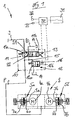
- a brake control system 1 a working machine, for example, a battery-electric or internal combustion engine operated, preferably designed as a forklift truck, described with a designed as a spring brake brake device 2, which forms a parking brake.
- a drive axle with two driven wheels which has two drive shafts 3a and 3b, which are each driven by a traction motor 4a and 4b.
- the drive shafts 3a, 3b can be braked and locked by a respective braking device, which is designed as a hydraulically releasable spring-loaded brake 5a or 5b.
- the spring-loaded brakes 5 a, 5 b are preferably designed as oil-cooled multi-disc brakes.
- the spring-loaded brakes 5a, 5b are each acted upon by a spring device 6a, 6b in a closed position forming the braking position, the force of the spring device defining a maximum braking force and thus a maximum deceleration.
- a brake release pressure chamber 7a or 7b is provided in each case, which counteracts when pressure is applied with a brake release pressure of the force of the spring means 6a, 6b to act on the spring brake 5a, 5b in a release position.
- the brake release pressure chambers 7a, 7b are connected to a common hydraulic brake release pressure line 8, which is connectable to a pressure supply line 9 of a pressure supply device not shown in detail.
- an electrically actuated brake valve device 10 is connected upstream.
- the brake valve device 10 comprises two electrically actuatable control valves 11, 12 which are each designed as a second-position valves.
- the first control valve 11 is arranged in the brake line 8 and is on the input side with the pressure supply line 9 and the output side with the brake release pressure line 8 in connection.
- the first control valve 11 has a blocking position 11a and a pressure build-up position for releasing the spring brake 5a, 5b formed flow position 11 b, wherein in the blocking position 11a the connection of the pressure supply line 9 shut off with the brake release pressure line 8 and in the flow position 11 b, the brake release pressure line 8 with the pressure supply line 9 is connected.
- the control valve 11 is acted upon by a spring in the blocking position 11a and acted upon by an electrical actuator 13, such as a solenoid, in the flow position 11 b.
- the control valve 11 is thus in the de-energized state in the blocking position 11a.
- the control valve 11 is actuated in the flow position 11 b, in which the brake release pressure chambers 7a, 7b are connected to the pressure supply line 9.
- the second control valve 12 has a blocking position 12a, in which the container branch line 15 is shut off, and designed as a pressure release position for the parking brake function flow position 12b, in which the container branch line 15 is opened and thus the Bremslprop Kunststoffschreib 7a, 7b are connected to the container 14.
- no further throttling valve devices are arranged in addition to the control valve 12.
- the control valve 12 is acted upon by a spring in the blocking position 12a and acted upon by an electrical actuator 16, such as a solenoid, in the flow position 12b.
- the control valve 12 is thus in the de-energized state in the blocking position 12a.
- the control valve 12 is actuated in the flow position 12b, in which the brake release pressure chambers 7a, 7b are connected via the container branch line 15 directly and without interposition of further valve means with the container 14.
- the first control valve 11 further controls in a redundant manner, the connection of the brake release pressure chambers 7a, 7b with the container 14.
- the control valve 11 has for this purpose a second control path which controls the connection of the brake release pressure chambers 7a, 7b with the container 14 and in the present embodiment of a control line 20 is formed.
- the control line 20 is in this case connected to the container branch line 15 and the brake release pressure line 8 between the first control valve 11 and the brake release pressure chamber 7a, 7b and guided to the container 14.
- a pressure reduction or pressure holding device 21 is arranged, which is preferably formed by a built-in the first control valve 11 throttle device 22, for example, a diaphragm in the second control path.
- the blocking position 11a of the first control valve 11 in this case forms via the second control path a pressure reduction position to achieve a safety function.
- the second control path and thus the control line 20 is shut off.
- the two control valves 11, 12 of the brake valve device 10 can be actuated by means of an electronic control device 30, which is the input side with an actuating means designed as a switch or pushbutton control element 31 in connection.
- an actuating means designed as a switch or pushbutton control element 31 in connection.
- a manual parking brake function can be achieved by the electronic control device 30 by corresponding activation of the two control valves 11, 12.
- At least one sensor device is connected to the input side of the control device 30, for example a seat occupancy switch 32 detecting the presence of the operator on a driver's workstation, for example a driver's seat, or a sensor 33 detecting the vehicle speed.
- a seat occupancy switch 32 detecting the presence of the operator on a driver's workstation, for example a driver's seat, or a sensor 33 detecting the vehicle speed.
- the second control valve 12 is de-energized and is in the blocking position 12a, in which the connection of the brake release pressure chambers 7a, 7b to the container 14 is interrupted and shut off.
- the first control valve 11 is acted upon in the flow position 11 b, in which the brake release pressure line 8 is connected to the pressure supply line 9.
- the flow position 11 b of the first control valve 11 thus forms a pressure build-up position for releasing the spring brake 5a, 5b, so that the brake release pressure chambers 7a, 7b hydraulically acted upon by a brake release pressure and thereby one of the spring force of the spring means 6a, 6b opposite force can be generated, whereby the Spring brakes 5a, 5b acted upon in the release position and thus be solved, which corresponds to an open parking brake.
- the second control path to the control line 20 is shut off, so that the container outlet of the first control valve 11 is closed.
- the brake release pressure required for releasing the spring-loaded brake 5a, 5b is thus made available via the pressure supply line 9.
- the spring brake 5a, 5b operating as a parking brake can, in the sense of an automatic parking brake, be provided with corresponding signals from the sensor devices 32 or 33 or applied in the sense of a manual parking brake upon actuation of the control element 31 in the braking position and thus closed when the first control valve 11 is no longer energized and thus de-energized and the second control valve 12 is energized.
- the first control valve 11 is thus acted upon in the blocking position 11a, in which the connection of the pressure supply line 9 with the brake release pressure line 8 and thus the pressure supply of the spring brake 5a, 5b is shut off and the second, formed by the control line 20 signal path is open.
- the second control valve 12 provides in the activated state in the formed as a pressure release flow position 12b for an immediate and sudden pressure reduction of the brake release pressure in the brake release pressure chambers 7a, 7b of the spring brakes 5a, 5b, so that the spring means 6a, 6b the spring brake 5a, 5b in the braking position applied and closes the parking brake.
- the working machine is thus braked with the maximum braking force, which are defined by the spring means 6a, 6b, and held at a standstill.
- both control valves 11, 12 are energized.
- the first control valve 11 and the second control valve 12 thus each switch into the blocking position 11a or 12a.
- the first control valve 11 is here in the blocking position 11 a, the second signal path, which is formed by the control line 20, free and allows a pressure reduction position in which the Bremslprop Kunststoffschreib 7 a, 7 b are connected via the pressure reduction or pressure holding device 21 to the container 14.
- a pressure reduction of the brake release pressure to a defined level or a time-delayed pressure reduction of the brake release pressure in the brake release pressure chamber 7a and 7b of the spring brakes 5a, 5b achieved so that they initially close with a reduced braking torque and the driving Working machine is decelerated according to a hydraulic ramp with a defined delay.
- load shedding of the transported load can be avoided in this safety function in the case of a work machine designed as an industrial vehicle during deceleration as a result of an electroless vehicle.
- the first control valve 11 blocks the connection of the brake release pressure line 8 to the pressure supply line 9. This ensures that no dynamic pressure between the brake release pressure chamber 7a, 7b and the pressure reduction or pressure-maintaining device 21 can build up, which would have a reduction in the braking force in the safety function result.
- an additional, redundant container connection of the brake-air pressure chambers 7a, 7b is achieved by the second signal path of the first control valve 11 in addition to the container connection of the brake-air pressure chambers 7a, 7b via the second control valve 12.
- the functional safety of the parking brake device 5a, 5b can be further increased.
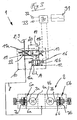
- FIG. 2 is a brake control system 1 described as a spring brake 2 brake device described which forms a service brake and a parking brake and thus in addition to the functions already described additionally has the function of a service brake for metered braking of the machine.
- the brake control system 1 corresponds in this case, in particular with respect to the structure and the function of the brake valve device 10, in the FIG. 1 shown construction.
- the spring brake 2 is here for example designed as a single-circuit brake system, in addition to the FIG. 1 a brake valve 40 is disposed upstream of the first control valve 11 in the brake pipe 8.
- the brake valve 40 may in this case be part of the brake valve device 10.
- the brake valve 40 is the input side to the pressure supply line 9 and the output side with a guided to the container 14 tank line 41 and the guided to the first control valve 11 brake release pressure line 8 in combination.
- the brake valve 40 is formed in the present embodiment, for example, as a controllable proportional pressure reducing valve with a falling characteristic.
- the brake valve 40 is mechanically actuated by an actuator 42, for example, a brake pedal or by the pedals of a so-called double pedal control, in each of which a drive / brake pedal the forward direction and a drive / brake pedal is assigned to the reverse direction.
- an actuator 42 for example, a brake pedal or by the pedals of a so-called double pedal control, in each of which a drive / brake pedal the forward direction and a drive / brake pedal is assigned to the reverse direction.
- the brake valve 40 is increasingly applied in a the brake release pressure line 8 with the container 14 guided to the container 14 line connecting position, so that by a metered reduction in the pending in the brake line 8 brake release pressure spring brake 5a, 5b to achieve a service brake function dosed in the braking position can be acted upon.
- the second control valve 12 is designed as a two-position two-port valve and the first control valve 11 is designed as a two-position four-port valve, in which the second signal path branches off from the container branch line 15.
- first control valve 11 form as a two-position three-port valve, in which the second signal path branches off from the brake release pressure line 8 between the first control valve 11 and the brake release pressure chamber 7a, 7b and thus guided to the container 14 control line 20 in the blocking position 11a of the control valve 11 to the terminal of the control valve 11th is connected, which is connected to the guided to the brake release pressure chambers 7a, 7b brake release pressure line 8.
- the two control valves 11, 12 of the brake valve device 10 according to the invention can in this case - as in the FIGS. 1 to 3 is shown - as in intermediate positions throttling proportional valves may be formed. Alternatively, it is also possible to design the two control valves 11, 12 as switching valves.
Landscapes
- Engineering & Computer Science (AREA)
- Transportation (AREA)
- Mechanical Engineering (AREA)
- Braking Systems And Boosters (AREA)
Claims (10)
- Système de commande de freinage d'une machine de travail mobile, notamment chariot élévateur, avec un dispositif de freinage prenant la forme d'un frein à accumulateur par ressort, notamment d'un dispositif de freinage fonctionnant comme un frein de stationnement pouvant être alimenté de façon hydraulique à l'aide d'une pression de déclenchement de frein régnant dans un espace de pression de déclenchement de frein en direction d'une position de déclenchement, sachant que pour commander le dispositif de freinage, un dispositif de soupape de frein électriquement actionnable est connecté en amont de l'espace de pression de déclenchement de frein et qu'une fonction de frein de stationnement manuel et/ou automatique ainsi qu'une fonction de sécurité peuvent être atteintes à l'aide du dispositif de soupape de frein, caractérisé en ce que le dispositif de soupape de frein (10) électriquement actionnable comporte une première soupape de commande (11) électriquement actionnable prenant la forme d'une soupape à deux positions et disposée dans une conduite de pression de déclenchement de frein (8) guidant la pression de déclenchement de frein et une position de verrouillage (11a) active à l'état sans débit ainsi qu'une position passante (11b) électriquement actionnable et englobe une deuxième soupape de commande (12) électriquement actionnable prenant la forme d'une soupape à deux positions, disposée dans une conduite à deux réservoirs (15) se divisant en partant de la conduite de pression de déclenchement de frein (8) entre la première soupape de commande (11) et l'espace de pression de déclenchement de frein (7a ; 7b) et guidée vers un réservoir (14) et comportant une position de verrouillage (12a) active à l'état sans débit ainsi qu'une position passante (12b) électriquement actionnable, la première soupape de commande (11) reliant à l'état sans débit l'espace de pression de déclenchement de frein (7a ; 7b) à un dispositif d'évacuation de pression ou de maintien de pression (21) ou au réservoir (14).
- Système de commande de freinage selon la revendication 1, caractérisé en ce que pour atteindre la fonction de frein de stationnement manuel et/ou automatique, la première soupape de commande (11) peut être alimentée par une connexion sans débit dans la position de verrouillage (11a) et que la deuxième soupape de commande (12) est alimentée par une excitation électrique dans la position passante (12b).
- Système de commande de freinage selon la revendication 1 ou 2, caractérisé en ce que la première soupape de commande (11) relie à l'état sans débit la conduite à deux réservoirs (15) ou la conduite de pression de déclenchement de frein (8), entre la première soupape de commande (11) et l'espace de pression de déclenchement de frein (7a ; 7b), au dispositif d'évacuation de pression ou de maintien de pression ou au réservoir (14).
- Système de commande de freinage selon l'une quelconque des, revendications 1 à 3, caractérisé en ce que le dispositif d'évacuation de pression ou de maintien de pression (21) est formé par un dispositif d'étranglement (22) intégré dans la première soupape de commande (11), notamment un diaphragme, et que la première soupape de commande (11) relie à l'état sans débit la conduite à deux réservoirs (15) ou la conduite de pression de déclenchement de frein (8), entre la première soupape de commande (11) et l'espace de pression de déclenchement de frein (7a ; 7b) au réservoir (14), via le dispositif d'étranglement (22).
- Système de commande de freinage selon l'une quelconque des revendications 1 à 4, caractérisé en ce que la première soupape de commande (11) bloque dans la position passante (11 b) la liaison de l'espace de pression de déclenchement de frein (7a ; 7b) avec le réservoir (14).
- Système de commande de freinage selon l'une quelconque des revendications 1 à 5, caractérisé en ce qu'un dispositif de commande électronique (30) est prévu pour actionner le dispositif de soupape de frein (10) électriquement actionnable.
- Système de commande de freinage selon la revendication 6, caractérisé en ce que le dispositif de commande électronique (30) est en liaison active du côté d'entrée avec un dispositif de détection (32 ; 32), notamment un capteur de vitesse ou un dispositif de détection détectant la présence d'une personne utilisatrice, sachant que la fonction de frein de stationnement automatique peut être atteinte en fonction du signal du dispositif de détection (32 ; 33).
- Système de commande de freinage selon la revendication 6 ou 7, caractérisé en ce que le dispositif de commande électronique (30) est en liaison active du côté d'entrée avec un élément de commande (31), notamment un bouton-poussoir ou un contacteur, sachant que la fonction de frein de stationnement manuelle peut être atteinte en fonction de l'actionnement de l'élément de commande (31) die.
- Système de commande de freinage selon l'une quelconque des revendications 1 à 8, caractérisé en ce que le frein à accumulateur par ressort (5a ; 5b) fonctionne comme un frein de service, une soupape de frein (40) étant associée à l'espace de pression de déclenchement de frein (7a ; 7b).
- Système de commande de freinage selon la revendication 9, caractérisé en ce que la première soupape de commande (11) est disposée dans la conduite de pression de déclenchement de frein (8) en aval de la soupape de frein (40).
Applications Claiming Priority (1)
| Application Number | Priority Date | Filing Date | Title |
|---|---|---|---|
| DE201010012886 DE102010012886A1 (de) | 2010-03-26 | 2010-03-26 | Bremssteuerungssystem einer mobilen Arbeitsmaschine, insbesondere Flurförderzeug |
Publications (3)
| Publication Number | Publication Date |
|---|---|
| EP2371639A2 EP2371639A2 (fr) | 2011-10-05 |
| EP2371639A3 EP2371639A3 (fr) | 2013-05-29 |
| EP2371639B1 true EP2371639B1 (fr) | 2015-12-16 |
Family
ID=43978003
Family Applications (1)
| Application Number | Title | Priority Date | Filing Date |
|---|---|---|---|
| EP11001727.4A Not-in-force EP2371639B1 (fr) | 2010-03-26 | 2011-03-02 | Système de commande de freinage d'une machine de travail mobile, notamment chariot élévateur |
Country Status (2)
| Country | Link |
|---|---|
| EP (1) | EP2371639B1 (fr) |
| DE (1) | DE102010012886A1 (fr) |
Families Citing this family (2)
| Publication number | Priority date | Publication date | Assignee | Title |
|---|---|---|---|---|
| DE102011116902A1 (de) * | 2011-10-25 | 2013-04-25 | Wabco Gmbh | Bremsverfahren und Bremseinrichtung für ein Fahrzeug sowie hydraulische Bremsanlage und Fahrzeug damit |
| DE102011116906A1 (de) | 2011-10-25 | 2013-04-25 | Wabco Gmbh | Bremsverfahren und Bremseinrichtung für ein Fahrzeug, hydraulische Bremsanlage und Fahrzeug damit |
Family Cites Families (4)
| Publication number | Priority date | Publication date | Assignee | Title |
|---|---|---|---|---|
| JPS58126246A (ja) * | 1982-01-21 | 1983-07-27 | Nippon Air Brake Co Ltd | ブレ−キ装置 |
| US5611199A (en) * | 1995-12-13 | 1997-03-18 | Caterpillar Inc. | Two stage electrohydraulic pressure control valve |
| DE102009031743B4 (de) | 2008-07-29 | 2022-01-20 | Linde Material Handling Gmbh | Fahrbare Arbeitsmaschine mit einer Bremse mit zwei Druckräumen |
| DE102009031742A1 (de) * | 2008-07-29 | 2010-02-04 | Linde Material Handling Gmbh | Fahrbare Arbeitsmaschine mit einer als Betriebsbremse und als automatische Feststellbremse betreibbaren Bremse |
-
2010
- 2010-03-26 DE DE201010012886 patent/DE102010012886A1/de not_active Withdrawn
-
2011
- 2011-03-02 EP EP11001727.4A patent/EP2371639B1/fr not_active Not-in-force
Also Published As
| Publication number | Publication date |
|---|---|
| EP2371639A3 (fr) | 2013-05-29 |
| DE102010012886A1 (de) | 2011-09-29 |
| EP2371639A2 (fr) | 2011-10-05 |
Similar Documents
| Publication | Publication Date | Title |
|---|---|---|
| DE102017118529B4 (de) | Elektronisch gesteuerte Anhänger-Bremssteuereinheit und Anhänger-Bremsanlage | |
| DE102009031743B4 (de) | Fahrbare Arbeitsmaschine mit einer Bremse mit zwei Druckräumen | |
| EP3034369B1 (fr) | Machine de travail mobile dotee d'un dispositif de freinage | |
| EP1199234B1 (fr) | Dispositif de déverrouillage de secours pour un frein de stationnement dans un véhicule automobile | |
| DE19530612C2 (de) | Steuerung einer automatischen Kupplung | |
| EP2650183B1 (fr) | Dispositif de soupape de frein de stationnement et installation de freinage à air comprimé pneumatique pour remorque | |
| EP1188634B1 (fr) | Soupape de frein de remorque pour remorques à commande de freinage électronique et à sécurité améliorée de remorque stationnée | |
| EP1199233B1 (fr) | Dispositif de commande pour un frein de stationnement pour véhicule automobile | |
| DE10146770A1 (de) | Bremsanlage für ein Fahrzeug | |
| DE102004033362A1 (de) | Hydraulikkreis für ein Doppelkupplungsgetriebe | |
| DE102018104143A1 (de) | Bremsanlage für einen Fahrzeugzug sowie damit ausgestattete Zugmaschine | |
| EP2368778B1 (fr) | Système de commande de freinage d'une machine de travail mobile, notamment chariot élévateur | |
| DE102009031741B4 (de) | Fahrbare Arbeitsmaschine mit Federspeicherbremse | |
| WO2021190703A1 (fr) | Dispositif de verrouillage de stationnement dans une configuration normalement verrouillée pour une chaîne cinématique | |
| DE102009031742A1 (de) | Fahrbare Arbeitsmaschine mit einer als Betriebsbremse und als automatische Feststellbremse betreibbaren Bremse | |
| DE102012106213A1 (de) | Arbeitsmaschine mit einem elektrischen Antriebssystem | |
| EP1938004A1 (fr) | Ensemble soupape de commande pour la commande d'un embrayage de demarrage d'une boite de vitesses automatique | |
| WO2022258097A1 (fr) | Actionneur pour un verrou de stationnement | |
| DE102011053568B4 (de) | Bremssteuerungssystem einer mobilen Arbeitsmaschine | |
| DE102011008707A1 (de) | Mobile Arbeitsmaschine, insbesondere Flurförderzeug | |
| DE102012106212A1 (de) | Bremssteuerungssystem einer mobilen Arbeitsmaschine | |
| EP2371639A2 (fr) | Système de commande de freinage d'une machine de travail mobile, notamment chariot élévateur | |
| WO2008086980A1 (fr) | Véhicule avec équipement de détection pre-safe | |
| DE102013107805B4 (de) | Bremssteuerungssystem einer mobilen Arbeitsmaschine, insbesondere Flurförderzeug | |
| DE102009005009A1 (de) | Fahrbare Arbeitsmaschine mit hydraulisch lösbarer Federspeicherbremse |
Legal Events
| Date | Code | Title | Description |
|---|---|---|---|
| PUAI | Public reference made under article 153(3) epc to a published international application that has entered the european phase |
Free format text: ORIGINAL CODE: 0009012 |
|
| AK | Designated contracting states |
Kind code of ref document: A2 Designated state(s): AL AT BE BG CH CY CZ DE DK EE ES FI FR GB GR HR HU IE IS IT LI LT LU LV MC MK MT NL NO PL PT RO RS SE SI SK SM TR |
|
| AX | Request for extension of the european patent |
Extension state: BA ME |
|
| PUAL | Search report despatched |
Free format text: ORIGINAL CODE: 0009013 |
|
| AK | Designated contracting states |
Kind code of ref document: A3 Designated state(s): AL AT BE BG CH CY CZ DE DK EE ES FI FR GB GR HR HU IE IS IT LI LT LU LV MC MK MT NL NO PL PT RO RS SE SI SK SM TR |
|
| AX | Request for extension of the european patent |
Extension state: BA ME |
|
| RIC1 | Information provided on ipc code assigned before grant |
Ipc: B60T 13/22 20060101AFI20130425BHEP Ipc: B60T 13/68 20060101ALI20130425BHEP |
|
| 17P | Request for examination filed |
Effective date: 20130830 |
|
| RBV | Designated contracting states (corrected) |
Designated state(s): AL AT BE BG CH CY CZ DE DK EE ES FI FR GB GR HR HU IE IS IT LI LT LU LV MC MK MT NL NO PL PT RO RS SE SI SK SM TR |
|
| GRAP | Despatch of communication of intention to grant a patent |
Free format text: ORIGINAL CODE: EPIDOSNIGR1 |
|
| INTG | Intention to grant announced |
Effective date: 20150629 |
|
| GRAS | Grant fee paid |
Free format text: ORIGINAL CODE: EPIDOSNIGR3 |
|
| GRAA | (expected) grant |
Free format text: ORIGINAL CODE: 0009210 |
|
| AK | Designated contracting states |
Kind code of ref document: B1 Designated state(s): AL AT BE BG CH CY CZ DE DK EE ES FI FR GB GR HR HU IE IS IT LI LT LU LV MC MK MT NL NO PL PT RO RS SE SI SK SM TR |
|
| REG | Reference to a national code |
Ref country code: GB Ref legal event code: FG4D Free format text: NOT ENGLISH |
|
| REG | Reference to a national code |
Ref country code: CH Ref legal event code: EP |
|
| REG | Reference to a national code |
Ref country code: IE Ref legal event code: FG4D Free format text: LANGUAGE OF EP DOCUMENT: GERMAN |
|
| REG | Reference to a national code |
Ref country code: AT Ref legal event code: REF Ref document number: 765416 Country of ref document: AT Kind code of ref document: T Effective date: 20160115 |
|
| REG | Reference to a national code |
Ref country code: DE Ref legal event code: R096 Ref document number: 502011008491 Country of ref document: DE |
|
| REG | Reference to a national code |
Ref country code: NL Ref legal event code: MP Effective date: 20151216 |
|
| REG | Reference to a national code |
Ref country code: LT Ref legal event code: MG4D |
|
| PG25 | Lapsed in a contracting state [announced via postgrant information from national office to epo] |
Ref country code: NO Free format text: LAPSE BECAUSE OF FAILURE TO SUBMIT A TRANSLATION OF THE DESCRIPTION OR TO PAY THE FEE WITHIN THE PRESCRIBED TIME-LIMIT Effective date: 20160316 Ref country code: LT Free format text: LAPSE BECAUSE OF FAILURE TO SUBMIT A TRANSLATION OF THE DESCRIPTION OR TO PAY THE FEE WITHIN THE PRESCRIBED TIME-LIMIT Effective date: 20151216 Ref country code: HR Free format text: LAPSE BECAUSE OF FAILURE TO SUBMIT A TRANSLATION OF THE DESCRIPTION OR TO PAY THE FEE WITHIN THE PRESCRIBED TIME-LIMIT Effective date: 20151216 |
|
| PG25 | Lapsed in a contracting state [announced via postgrant information from national office to epo] |
Ref country code: LV Free format text: LAPSE BECAUSE OF FAILURE TO SUBMIT A TRANSLATION OF THE DESCRIPTION OR TO PAY THE FEE WITHIN THE PRESCRIBED TIME-LIMIT Effective date: 20151216 Ref country code: GR Free format text: LAPSE BECAUSE OF FAILURE TO SUBMIT A TRANSLATION OF THE DESCRIPTION OR TO PAY THE FEE WITHIN THE PRESCRIBED TIME-LIMIT Effective date: 20160317 Ref country code: SE Free format text: LAPSE BECAUSE OF FAILURE TO SUBMIT A TRANSLATION OF THE DESCRIPTION OR TO PAY THE FEE WITHIN THE PRESCRIBED TIME-LIMIT Effective date: 20151216 Ref country code: FI Free format text: LAPSE BECAUSE OF FAILURE TO SUBMIT A TRANSLATION OF THE DESCRIPTION OR TO PAY THE FEE WITHIN THE PRESCRIBED TIME-LIMIT Effective date: 20151216 Ref country code: RS Free format text: LAPSE BECAUSE OF FAILURE TO SUBMIT A TRANSLATION OF THE DESCRIPTION OR TO PAY THE FEE WITHIN THE PRESCRIBED TIME-LIMIT Effective date: 20151216 Ref country code: NL Free format text: LAPSE BECAUSE OF FAILURE TO SUBMIT A TRANSLATION OF THE DESCRIPTION OR TO PAY THE FEE WITHIN THE PRESCRIBED TIME-LIMIT Effective date: 20151216 |
|
| PG25 | Lapsed in a contracting state [announced via postgrant information from national office to epo] |
Ref country code: IT Free format text: LAPSE BECAUSE OF FAILURE TO SUBMIT A TRANSLATION OF THE DESCRIPTION OR TO PAY THE FEE WITHIN THE PRESCRIBED TIME-LIMIT Effective date: 20151216 Ref country code: CZ Free format text: LAPSE BECAUSE OF FAILURE TO SUBMIT A TRANSLATION OF THE DESCRIPTION OR TO PAY THE FEE WITHIN THE PRESCRIBED TIME-LIMIT Effective date: 20151216 Ref country code: ES Free format text: LAPSE BECAUSE OF FAILURE TO SUBMIT A TRANSLATION OF THE DESCRIPTION OR TO PAY THE FEE WITHIN THE PRESCRIBED TIME-LIMIT Effective date: 20151216 |
|
| PG25 | Lapsed in a contracting state [announced via postgrant information from national office to epo] |
Ref country code: BE Free format text: LAPSE BECAUSE OF NON-PAYMENT OF DUE FEES Effective date: 20160331 Ref country code: PT Free format text: LAPSE BECAUSE OF FAILURE TO SUBMIT A TRANSLATION OF THE DESCRIPTION OR TO PAY THE FEE WITHIN THE PRESCRIBED TIME-LIMIT Effective date: 20160418 Ref country code: EE Free format text: LAPSE BECAUSE OF FAILURE TO SUBMIT A TRANSLATION OF THE DESCRIPTION OR TO PAY THE FEE WITHIN THE PRESCRIBED TIME-LIMIT Effective date: 20151216 Ref country code: IS Free format text: LAPSE BECAUSE OF FAILURE TO SUBMIT A TRANSLATION OF THE DESCRIPTION OR TO PAY THE FEE WITHIN THE PRESCRIBED TIME-LIMIT Effective date: 20160416 Ref country code: RO Free format text: LAPSE BECAUSE OF FAILURE TO SUBMIT A TRANSLATION OF THE DESCRIPTION OR TO PAY THE FEE WITHIN THE PRESCRIBED TIME-LIMIT Effective date: 20151216 Ref country code: SK Free format text: LAPSE BECAUSE OF FAILURE TO SUBMIT A TRANSLATION OF THE DESCRIPTION OR TO PAY THE FEE WITHIN THE PRESCRIBED TIME-LIMIT Effective date: 20151216 Ref country code: SM Free format text: LAPSE BECAUSE OF FAILURE TO SUBMIT A TRANSLATION OF THE DESCRIPTION OR TO PAY THE FEE WITHIN THE PRESCRIBED TIME-LIMIT Effective date: 20151216 |
|
| REG | Reference to a national code |
Ref country code: DE Ref legal event code: R097 Ref document number: 502011008491 Country of ref document: DE |
|
| PLBE | No opposition filed within time limit |
Free format text: ORIGINAL CODE: 0009261 |
|
| STAA | Information on the status of an ep patent application or granted ep patent |
Free format text: STATUS: NO OPPOSITION FILED WITHIN TIME LIMIT |
|
| PG25 | Lapsed in a contracting state [announced via postgrant information from national office to epo] |
Ref country code: DK Free format text: LAPSE BECAUSE OF FAILURE TO SUBMIT A TRANSLATION OF THE DESCRIPTION OR TO PAY THE FEE WITHIN THE PRESCRIBED TIME-LIMIT Effective date: 20151216 Ref country code: PL Free format text: LAPSE BECAUSE OF FAILURE TO SUBMIT A TRANSLATION OF THE DESCRIPTION OR TO PAY THE FEE WITHIN THE PRESCRIBED TIME-LIMIT Effective date: 20151216 Ref country code: LU Free format text: LAPSE BECAUSE OF FAILURE TO SUBMIT A TRANSLATION OF THE DESCRIPTION OR TO PAY THE FEE WITHIN THE PRESCRIBED TIME-LIMIT Effective date: 20160302 Ref country code: MC Free format text: LAPSE BECAUSE OF FAILURE TO SUBMIT A TRANSLATION OF THE DESCRIPTION OR TO PAY THE FEE WITHIN THE PRESCRIBED TIME-LIMIT Effective date: 20151216 |
|
| REG | Reference to a national code |
Ref country code: CH Ref legal event code: PL |
|
| 26N | No opposition filed |
Effective date: 20160919 |
|
| GBPC | Gb: european patent ceased through non-payment of renewal fee |
Effective date: 20160316 |
|
| REG | Reference to a national code |
Ref country code: IE Ref legal event code: MM4A |
|
| REG | Reference to a national code |
Ref country code: FR Ref legal event code: ST Effective date: 20161130 |
|
| REG | Reference to a national code |
Ref country code: DE Ref legal event code: R082 Ref document number: 502011008491 Country of ref document: DE Representative=s name: PATENTSHIP PATENTANWALTSGESELLSCHAFT MBH, DE |
|
| PG25 | Lapsed in a contracting state [announced via postgrant information from national office to epo] |
Ref country code: CH Free format text: LAPSE BECAUSE OF NON-PAYMENT OF DUE FEES Effective date: 20160331 Ref country code: GB Free format text: LAPSE BECAUSE OF NON-PAYMENT OF DUE FEES Effective date: 20160316 Ref country code: IE Free format text: LAPSE BECAUSE OF NON-PAYMENT OF DUE FEES Effective date: 20160302 Ref country code: FR Free format text: LAPSE BECAUSE OF NON-PAYMENT OF DUE FEES Effective date: 20160331 Ref country code: LI Free format text: LAPSE BECAUSE OF NON-PAYMENT OF DUE FEES Effective date: 20160331 |
|
| REG | Reference to a national code |
Ref country code: DE Ref legal event code: R082 Ref document number: 502011008491 Country of ref document: DE Representative=s name: PATENTSHIP PATENTANWALTSGESELLSCHAFT MBH, DE |
|
| PG25 | Lapsed in a contracting state [announced via postgrant information from national office to epo] |
Ref country code: SI Free format text: LAPSE BECAUSE OF FAILURE TO SUBMIT A TRANSLATION OF THE DESCRIPTION OR TO PAY THE FEE WITHIN THE PRESCRIBED TIME-LIMIT Effective date: 20151216 |
|
| REG | Reference to a national code |
Ref country code: AT Ref legal event code: MM01 Ref document number: 765416 Country of ref document: AT Kind code of ref document: T Effective date: 20160302 |
|
| PG25 | Lapsed in a contracting state [announced via postgrant information from national office to epo] |
Ref country code: AT Free format text: LAPSE BECAUSE OF NON-PAYMENT OF DUE FEES Effective date: 20160302 Ref country code: MT Free format text: LAPSE BECAUSE OF FAILURE TO SUBMIT A TRANSLATION OF THE DESCRIPTION OR TO PAY THE FEE WITHIN THE PRESCRIBED TIME-LIMIT Effective date: 20151216 |
|
| PG25 | Lapsed in a contracting state [announced via postgrant information from national office to epo] |
Ref country code: HU Free format text: LAPSE BECAUSE OF FAILURE TO SUBMIT A TRANSLATION OF THE DESCRIPTION OR TO PAY THE FEE WITHIN THE PRESCRIBED TIME-LIMIT; INVALID AB INITIO Effective date: 20110302 Ref country code: CY Free format text: LAPSE BECAUSE OF FAILURE TO SUBMIT A TRANSLATION OF THE DESCRIPTION OR TO PAY THE FEE WITHIN THE PRESCRIBED TIME-LIMIT Effective date: 20151216 |
|
| PG25 | Lapsed in a contracting state [announced via postgrant information from national office to epo] |
Ref country code: TR Free format text: LAPSE BECAUSE OF FAILURE TO SUBMIT A TRANSLATION OF THE DESCRIPTION OR TO PAY THE FEE WITHIN THE PRESCRIBED TIME-LIMIT Effective date: 20151216 Ref country code: MK Free format text: LAPSE BECAUSE OF FAILURE TO SUBMIT A TRANSLATION OF THE DESCRIPTION OR TO PAY THE FEE WITHIN THE PRESCRIBED TIME-LIMIT Effective date: 20151216 |
|
| PG25 | Lapsed in a contracting state [announced via postgrant information from national office to epo] |
Ref country code: BG Free format text: LAPSE BECAUSE OF FAILURE TO SUBMIT A TRANSLATION OF THE DESCRIPTION OR TO PAY THE FEE WITHIN THE PRESCRIBED TIME-LIMIT Effective date: 20151216 |
|
| PG25 | Lapsed in a contracting state [announced via postgrant information from national office to epo] |
Ref country code: AL Free format text: LAPSE BECAUSE OF FAILURE TO SUBMIT A TRANSLATION OF THE DESCRIPTION OR TO PAY THE FEE WITHIN THE PRESCRIBED TIME-LIMIT Effective date: 20151216 |
|
| PGFP | Annual fee paid to national office [announced via postgrant information from national office to epo] |
Ref country code: DE Payment date: 20200324 Year of fee payment: 10 |
|
| REG | Reference to a national code |
Ref country code: DE Ref legal event code: R119 Ref document number: 502011008491 Country of ref document: DE |
|
| PG25 | Lapsed in a contracting state [announced via postgrant information from national office to epo] |
Ref country code: DE Free format text: LAPSE BECAUSE OF NON-PAYMENT OF DUE FEES Effective date: 20211001 |