EP2371653B1 - Véhicule ferroviaire avec portes coulissantes - Google Patents
Véhicule ferroviaire avec portes coulissantes Download PDFInfo
- Publication number
- EP2371653B1 EP2371653B1 EP10251350.4A EP10251350A EP2371653B1 EP 2371653 B1 EP2371653 B1 EP 2371653B1 EP 10251350 A EP10251350 A EP 10251350A EP 2371653 B1 EP2371653 B1 EP 2371653B1
- Authority
- EP
- European Patent Office
- Prior art keywords
- door
- railway vehicle
- side sliding
- disposed
- sliding door
- Prior art date
- Legal status (The legal status is an assumption and is not a legal conclusion. Google has not performed a legal analysis and makes no representation as to the accuracy of the status listed.)
- Not-in-force
Links
- 239000000725 suspension Substances 0.000 claims description 31
- 229920001971 elastomer Polymers 0.000 claims description 28
- 239000005060 rubber Substances 0.000 claims description 28
- 238000005096 rolling process Methods 0.000 claims description 17
- 238000005299 abrasion Methods 0.000 claims description 2
- 238000012423 maintenance Methods 0.000 description 12
- 239000000428 dust Substances 0.000 description 5
- 230000000737 periodic effect Effects 0.000 description 3
- 238000007689 inspection Methods 0.000 description 2
- 230000002787 reinforcement Effects 0.000 description 2
- 238000007789 sealing Methods 0.000 description 2
- XLYOFNOQVPJJNP-UHFFFAOYSA-N water Substances O XLYOFNOQVPJJNP-UHFFFAOYSA-N 0.000 description 2
- 238000004140 cleaning Methods 0.000 description 1
- 230000003247 decreasing effect Effects 0.000 description 1
- 239000005357 flat glass Substances 0.000 description 1
- 230000006698 induction Effects 0.000 description 1
- 238000004519 manufacturing process Methods 0.000 description 1
- 239000000463 material Substances 0.000 description 1
- 238000000465 moulding Methods 0.000 description 1
Images



Classifications
-
- B—PERFORMING OPERATIONS; TRANSPORTING
- B61—RAILWAYS
- B61D—BODY DETAILS OR KINDS OF RAILWAY VEHICLES
- B61D19/00—Door arrangements specially adapted for rail vehicles
- B61D19/003—Door arrangements specially adapted for rail vehicles characterised by the movements of the door
- B61D19/005—Door arrangements specially adapted for rail vehicles characterised by the movements of the door sliding
-
- B—PERFORMING OPERATIONS; TRANSPORTING
- B61—RAILWAYS
- B61D—BODY DETAILS OR KINDS OF RAILWAY VEHICLES
- B61D19/00—Door arrangements specially adapted for rail vehicles
- B61D19/02—Door arrangements specially adapted for rail vehicles for carriages
Definitions
- the present invention relates to railway vehicles having side sliding doors through which crews and passengers get on or off the railway vehicle, and especially, relates to railway vehicles having an externally suspended side sliding door device that opens and closes along an outer side of a side structure of the railway vehicle.
- railway vehicles have side sliding door devices disposed on openings formed on side structures of the vehicle for through which passengers and crews get on or off the vehicle.
- side sliding doors There are two types of conventional side sliding doors, an internally suspended slide sliding door device and an externally suspended side sliding door device.
- the internally suspended system has side sliding doors disposed on the inner side of the side structure of the car body, and the externally suspended system has side sliding doors disposed on the outer side of the side structure of the car body.
- the side sliding doors open and close along the longitudinal direction of the side structure.
- the internally suspended side sliding door device must have door pockets on the inner side of the side structure for housing the side sliding doors so as to prevent passengers' clothes and the like from being caught in the side sliding doors during opening and closing operation.
- the externally suspended side sliding door device does not require door pockets disposed on the inner side of the side structure since the side sliding doors are opened and closed along the outer side of the car body.
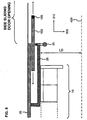
- FIG. 8 is a cross-sectional view showing an example of the prior art internally suspended side sliding door device, wherein the device is shown in a cross-section perpendicular to the height direction thereof.
- a side sliding door 100 of the internally suspended side sliding door device is opened and closed along an inner side surface of the side structure 20.
- a door pocket 26 for housing the side sliding door 100 is disposed on an inner side surface of the side structure 20.
- Interior equipments such as seats 15 and hand rails 28 are disposed on a side of the door pocket 26 facing the center of the car body 400.
- the distance L0 from the door pocket 26 to the center of the car body 400 in the width direction (300) of the railway vehicle is smaller than the distance from the side structure 20 to the center of the car body 400 in the width direction of the car body, corresponding to the thickness of the door pocket 26.
- the rigidity of the opening (area where the side sliding door 100 is disposed) of the side structure 20 is decreased, and a high stress may occur by the deformation caused near the opening of the side structure 20.
- reinforcement members disposed on the side structure 20 on the inner side of the car body may interfere with the door pocket 26, since the door pocket 26 of the internally suspended side sliding door device is disposed on the side structure 20 facing the inner side of the car body.
- the structure of the reinforcement area including the door pocket 26 will become complex in order to prevent such interference, and the number of designing and manufacturing steps thereof is increased.
- the internally suspended side sliding door device not only the number of components required for forming the door pocket 26 is increased, but also the interior design of the vehicle must be varied between the portion having the door pocket 26 and the portion without the door pocket 26.
- the internally suspended side sliding door device is advantageous since the upper door rail for guiding the side sliding door 100 during opening and closing operation and the door suspension device for suspending the side sliding door 100 and moving via rolling motion along the upper door rails is disposed on the inner side of the car body, according to which the water-resisting property and the dust-resisting property of the door suspension device can be ensured easily and the reliability thereof can be maintained.
- the upper door rail for guiding the side sliding doors and the door suspension device moving via rolling motion on the upper door rail is disposed on the outer side of the car body on the side wall of the railway vehicle. Therefore, in the externally suspended side sliding door device, it is necessary to ensure the reliability of these rolling motion units and to ensure the water-resisting property and the dust-resisting property so as to prevent rain water and wind from entering the car body (prevent wind containing dust from entering the car body) through the gap formed between the side sliding doors and the car structure. Furthermore, it is desirable that the structure of the device allows the door suspension device subjected to periodic maintenance to be easily maintained.
- patent document 1 discloses a structure in which the side sliding doors of an internally suspended side sliding door device is guided via an upper door rail disposed on an arm provided on the structure of the railway vehicle.
- the problem to be solved in a railway vehicle having an externally suspended side sliding door device that opens and closes along an outer side of the car of the side structure of the railway vehicle is to ensure the water-resisting property and the dust-resisting property of the side sliding doors with respect to the roof structure, the side structure and the underframe, to improve the reliability of the door suspension device suspending the side sliding doors and moving via rolling motion on the upper door rail for guiding the side sliding doors, and to facilitate the maintenance operation thereof.
- US 4,150,509 suggests a sliding doors and seals system and a passenger vehicle having such system.
- US 5,927,015 suggests an automatic door system for mass transit vehicles utilizing a linear induction motor for powering door panels from open to closed.
- the present invention aims at solving the problems of the prior art by providing a railway vehicle having an externally suspended side sliding door device opening and closing along a plane on an outer side of the railway vehicle, having an ensured water-resisting property and a dust-resisting property of the side sliding doors with respect to the roof structure, the side structure and the underframe, capable of improving the reliability of the door suspension device supporting the side sliding doors in suspended manner and moving along the upper door rail via rolling motion for guiding the side sliding doors, and capable of facilitating maintenance of the side sliding door device.
- the present invention provides a railway vehicle according to claim 1.
- the present invention provides a railway vehicle having an externally suspended side sliding door device opening and closing along the side surface on the outer side of the railway vehicle, having an ensured water-resisting property and dust-resisting property of the side sliding door with respect to the roof structure, the side structure and the underframe, an improved reliability of the door suspension device supporting the side sliding door in suspended manner and moving in rolling motion along the upper door rail for guiding the side sliding door, and facilitating the maintenance thereof.
- the externally suspended side sliding door device has a tongue portion extending downward in a continuous manner from a lower end portion of the side sliding door, wherein the tongue portion is guided along a lower door rail disposed on a step, and a slip-proof member is attached removably on an upper side of the step from both the inner side of the car and the outer side of the car towards and adjacent to the tongue portion, according to which the height of the side sliding doors (positioning of the doors) can be adjusted easily, and the efficiency of maintenance operations including cleaning can be improved.
- a railway vehicle is a general term referring to vehicles guided via a guide way, such as railway cars, streetcars, monorails and vehicles of new transport systems.
- railway cars such as railway cars, streetcars, monorails and vehicles of new transport systems.
- FIG. 1 is a perspective view showing an example of the railway vehicle having the externally suspended side sliding door device.
- a railway vehicle 1 comprises an underframe 10 constituting a floor surface of the car body, side structures 20 and 20 (only one side of which is illustrated) erected on both width-direction ends of the underframe 10, end structures 30 and 30 (only one side of which is illustrated) erected on both longitudinal ends of the underframe 10, and a roof structure 40 disposed on the upper ends of the side structures 20 and 20 and the end structures 30 and 30. Openings are provided on portions of the side structures 20 and 20 where doors through which passengers get on and off the vehicle and windows are to be formed, and on these openings are provided externally suspended side sliding door devices described in detail later and window glasses.
- External covers 22 and 22 covering upper door rails of the side sliding doors and door suspension devices rolling along the upper door rails and supporting the side sliding doors in a suspended manner are disposed along the longitudinal direction of the railway vehicle at the outer side of the car at connecting portions (door roof portions) between the side structures 20 and 20 and the roof structure 40.
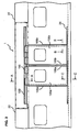
- FIG. 2 is a side view showing an enlarged view of the portion of the railway vehicle illustrated in FIG. 1 where the externally suspended side sliding door device is disposed
- FIG. 3 is a cross-sectional view taken at A-A of the railway vehicle illustrated in FIG. 2 showing the upper portion of the externally suspended side sliding door device.
- the externally suspended side sliding door device is mainly composed of side sliding doors 100a and 100b, an upper door rail 130 for guiding the opening and closing operation of the side sliding doors 100a and 100b, a door suspension device 140 moving in rolling motion on the upper door rail 130 and supporting the side sliding doors 100a and 100b in a suspended manner, a door engine 110 for generating driving power for opening and closing the side sliding doors 100a and 100b, and a lower door rail 134 for guiding a lower end portion of the side sliding doors 100a and 100b (refer to FIG. 6 ).
- the upper door rail 130 is disposed along the longitudinal direction of the railway vehicle 1 at the upper portion of the side wall on the outer side of the railway vehicle 1.
- the cross-sectional shape of the upper door rail 130 perpendicular to the longitudinal direction of the rail is composed of portions (planes) extending horizontally from upper and lower ends of a vertically disposed plate.
- One end of a door suspension fitting 150 is fixed to the upper end of the side sliding doors 100a and 100b, and a door suspension device 140 is fixed to the other end of the door suspension fitting 150.
- the door suspension device 140 is a device for supporting the side sliding doors 100a and 100b and the door suspension fitting 150 in a suspended manner, and the device 140 is disposed in such a manner so as to move in rolling motion on the upper door rail 130.
- the external cover 22 which is normally disposed in the area shown by the two dotted dashed lines, is omitted from the drawing, so as to show how the upper door rail 130 and the door suspension fitting 150 are disposed.
- the actual structure for enabling the door suspension device 140 to be moved in rolling motion on the upper door rail 130 can preferably adopt a rolling movement structure such as door rollers, balls, rollers and wheels.
- door head rubbers 105a and 105b are disposed on door close portions opposed to one another when the side sliding door 100a and the side sliding door 100b are closed.
- the cross-sectional shape of one of the door head rubbers 105a perpendicular to the longitudinal direction has at a center of a base portion of the door head rubber a projecting portion formed to project from the base portion toward the door close direction, and a space is formed in the interior of the projecting portion.
- the cross-sectional shape of the other door head rubber 105b perpendicular to the longitudinal direction has a wall portion projected toward the door close direction on each end in the base portion of the door head rubber, and a projecting portion projected to a height smaller than the projecting portion formed on one door head rubber 105a is disposed at the center of the base portion.
- Door tail rubbers 106a and 106b are disposed along the height direction on opposite ends of the side sliding doors 100a and 100b from the door head rubbers 105a and 105b. Details will follow, but contact portions 107a and 107a formed integrally with the door tail rubbers 106a and 106b (refer to FIG. 6 ) contact receivers 25 disposed in the perpendicular direction on a plane on the outer side of the side structure when the doors are closed, thereby ensuring the water-resisting property and a dust-resisting property of the side sliding doors 100a and 100b with respect to the side structures 20.
- a tongue portion 102 is formed to extend downward from the lower end portion of the side sliding doors 100a and 100b, wherein the tongue portion 102 is guided along the lower door rail 134 disposed on the step 24 (refer to FIG. 7 ).
- a step 24 is a member having a horizontal plane disposed along the longitudinal direction of the railway vehicle 1 at the width-direction end of the underframe 10 or at the lower end in the height direction of the side structure 20 at a height corresponding to the upper surface height of a platform (not shown), so as to connect the platform and the opening on the railway vehicle for the getting on and off.
- the water-resisting property and the dust-resisting property of the lower end portion of the side sliding doors 100a and 100b with respect to the step 24 will be described with reference to the embodiment illustrated in FIG. 7 .
- FIG. 3 is an A-A cross-sectional view showing the upper portion of the externally suspended side sliding door device disposed on the railway vehicle 1 illustrated in FIG. 2 .
- An upper door rail support member 132 is fixed to a slanted surface (door roof portion) on both ends of the roof structure 40 in the width direction 300, and on the perpendicular surface of the upper door rail support member 132 is disposed the upper door rail 130.
- One end of the door suspension fitting 150 is fixed to the upper end of the side sliding doors 100a, and the door suspension device 140 is fixed to the other end of the door suspension fitting 150.
- the door suspension device 140 supports the side sliding doors 100a and 100b in suspended manner so as to move in rolling motion along the upper door rail 130.
- a door engine 110 for opening and closing the side sliding door 100a (100b) is disposed on the inner side of the car body at the width-direction ends of the roof structure 40, wherein the door engine 110 and the side sliding door 100a (100b) are connected via a connecting bracket 120.
- driving power is transmitted via the connecting bracket 120 to the side sliding door 100a (100b), by which the side sliding doors 100a and 100b are opened and closed.
- the design of the interior of the railway vehicle is improved by providing a ceiling 180 on the inner side of the car and a cover 190 which covers the area on the inner side of the car at the width-direction ends of the ceiling 180 and the side structures 20 so that the door engine 110 and the connecting bracket 120 are not visible to the passengers.
- the cover 190 is attached so that it can be opened and closed, and the cover 190 can be opened, for example, to strengthen the engagement of bolts or the like fixing the connecting bracket 120, or to perform inspection and maintenance operation of the door engine 110.
- the door suspension device 140 can be moved in rolling motion along the perpendicular plane or one of the horizontal planes of the upper door rail 130, according to which biased abrasion caused by partial contact of the rolling portion can be prevented and the reliability thereof can be improved, so that the interval of periodic maintenance can be extended.
- An attachment section 42 for attaching the external cover 22 is disposed along the longitudinal direction of the roof structure 40 substantially on the width-direction ends of the horizontal plane of the roof structure 40.
- An engagement portion 23 is disposed on the height-direction end of the external cover 22, the engagement portion 23 being engaged with the attachment section 42 of the roof structure 40, and the external cover 22 is fixed if necessary via bolts or the like to the roof structure 40 or the side structure 20.
- the external cover 22 is removed during maintenance and inspection of the upper door rail 130 and the door suspension device 140, for example.
- the engagement portion 23 on the external cover 22 and the attachment section 42 on the roof structure 40 By disposing the engagement portion 23 on the external cover 22 and the attachment section 42 on the roof structure 40, the external cover 22 can easily be engaged to the roof structure 40 during attachment and detachment of the external cover 22, and the external cover 22 can be prevented from being dropped accidentally.
- the upper door rail 130 and the door suspension device 140 can be efficiently inspected and maintained.
- Weather strip members 200a and 200b are provided at the lower end of the external cover 22 on the side facing the side sliding doors 100a and 100b.
- Weather strip members 200a (200b) and 210a (210b) are formed for example of elastic rubber or foamed material (sponge).
- Weather strip members 210a (210b) are disposed at the upper ends of the side sliding doors 100a (100b) on the side facing the external cover 22 so as to oppose to the weather strip members 200a (200b).
- weather strip members 200a (200b) and 210a (210b) are integrated when the side sliding doors 100a and 100b are closed, thereby sealing the gap formed between the lower end of the external cover 22 and the upper end of the side sliding doors 100a and 100b, so as to improve the water-resisting property and the dust-resisting property with respect to the upper door rail 130 and the door suspension device 140.
- the reliability of the upper door rail 130 and the door suspension device 140 can be enhanced, and the interval of periodic maintenance can be elongated.
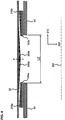
- FIG. 4 is a cross-sectional view showing the upper portion of the externally suspended side sliding door device of the railway vehicle illustrated in FIG. 3 in which the side sliding doors 100a and 100b are opened (cross-sectional view taken at D-D of FIG. 3 )
- FIG. 5 is a cross-sectional view of the externally suspended side sliding door device shown in FIG. 3 in which the side sliding doors are closed (cross-sectional view taken at D-D of FIG. 3 ).
- Weather strip members 200a and 200b disposed at the lower end of the external cover 22 on the side facing the side sliding door 100a are wedge shaped in which the thickness of the weather strip members 200a and 200b (width direction 300) is gradually increased toward a position P (door stop section) in which the door head rubbers are opposed to one another when the side sliding doors 100a and 100b are closed.
- Weather strip members 210a and 210b disposed at the upper end of the side sliding doors 100a and 100b on the side facing the external cover 22 are wedge shaped in which the thickness of the weather strip members 200a and 200b(width direction 300) is gradually reduced toward a position P in which the door head rubbers are opposed to one another when the side sliding doors 100a and 100b are closed.
- the opposing slanted surfaces of the weather strip members 200a and 200b and the weather strip members 210a and 210b contact one another, by which the gap formed between the external cover 22 and the side sliding doors 100 is sealed.
- rainwater and dust entering through the gap formed between the external cover 22 and the side sliding doors 100 can be prevented from reaching the upper door rail 130 and the door suspension device 140 provided on the external side of the roof structure 40 disposed above the side sliding doors 100, according to which the reliability of these devices can be maintained and the maintenance cycle thereof can be elongated.
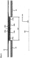
- FIG. 6 is a cross-sectional view taken at a plane perpendicular to the height direction at the width-direction ends of the externally suspended side sliding door device (cross-sectional view taken at B-B of FIG. 2 ).
- Door tail rubbers 106a and 106b are disposed along the height direction on both side ends in the width direction of the side sliding doors 100a and 100b (in the longitudinal direction 310 of the vehicle).
- Contact portions 107b and 107b are formed via integral molding on the door tail rubber 106b toward the width direction 300 of the vehicle.
- Contact portions 107b and 107b are formed of two substantially parallel flat panels extending toward the car width direction 300 from the door tail rubber 106b.
- the contact portions 107b and 107b come into contact with a receiver 25 disposed along the perpendicular edge of the opening formed on the side structure 20 for the getting on and off.
- the contact portion 107b positioned close to the door head rubber 105b comes into contact with the contact portion receiver 25.
- the contact portions 107b and 107b are formed as two flat panels placed at a distance from one another and disposed substantially parallel to one another, according to which the contact portion 107b coming in contact with the receiver 25 is prevented from being collapsed excessively.
- the contact portion 107b on the door tail rubber 106a and 106b coming into contact with the receiver 25 will be deformed elastically, sealing the gap between the side sliding door 100b near the door tail rubber 106b and the side structure 20, ensuring the water-resisting property and the dust-resisting property thereof.
- wind containing rain water and dust can be prevented from entering the interior of the railway vehicle 1, so that a pleasant in-car environment can be maintained.
- the contact portion 107b attached to the door tail rubber 106b of the side sliding door 100b has been described up to now, but the contact portions 107a and 107a attached to the door tail rubber 106a disposed on the side sliding door 100a also function in the same manner.
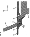
- FIG. 7 is a cross-sectional view (cross-sectional view taken at C-C of FIG. 2 ) showing the state in which the lower end of the side sliding doors 100a and 100b of the externally suspended side sliding door device is guided along the lower door rail 134 embedded in the step 24.
- a tongue portion 102 is disposed on the lower end of the side sliding doors 100a and 100b so as to be suspended continuously from the side sliding doors 100a and 100b.
- a sliding member 104 is disposed on the leading end portion of the tongue portion 102.
- a step 24 is disposed on the outer side of the vehicle at the portion of the underframe 10 where the side sliding doors 100a and 100b are disposed (refer to FIG. 1 ).
- the lower door rail 134 in the shape of a groove with an opening formed in the upper direction is formed on the step 24, and the tongue portion 102 is stored within the lower door rail 134 for guiding the tongue portion 102.
- the sliding member 104 functions to facilitate the rolling motion of the tongue portion 102 within the lower door rail 134.
- Slip-proof members 14 and 14 are disposed on the upper surface of the step 24 toward both the inner side and the outer side of the vehicle from the tongue portion 102.
- the position of the side sliding doors 100a and 100b in the vertical direction (the direction of arrow 320) can be adjusted without having to adjust the position of the slip-proof members 14 and 14 disposed on the lower door rail 134 in the width direction (in the direction of the arrow 300). Therefore, during maintenance of the side sliding doors 100a and 100b, such as replacement of the door suspension device 140 or the like, the replacement operation can be performed easily by adjusting only the vertical position of the side sliding doors 100a and 100b without having to adjust the width direction positions thereof.
- the lower door rail 134 has a recessed shape (groove shape) and is not projected from the step 24, the passengers getting on and off the railway vehicle 1 will not trip on the rail 134. Further, the dust accumulating on the lower door rail 134 can be cleaned easily by removing the removable slip-proof members 14 and 14, so that the maintenance time can be shortened.
- An example has been illustrated in which the sliding member 104 is disposed on the leading end of the tongue portion 102 so as to reduce the friction between the tongue portion 102 disposed on the lower ends of the side sliding doors 100a and 100b and the lower door rail 134 formed on the step 24, but the sliding member 104 can also be disposed on the lower door rail 134.
- two side sliding doors 100a and 100b opposed to one another are disposed, but the present invention can also be applied to an externally suspended side sliding door device composed only of a single side sliding door 100a.
Landscapes
- Engineering & Computer Science (AREA)
- Mechanical Engineering (AREA)
- Support Devices For Sliding Doors (AREA)
- Wing Frames And Configurations (AREA)
Claims (7)
- Véhicule ferroviaire (1) ayant un dispositif de porte coulissante latérale extérieurement suspendu, dans lequel le dispositif de porte coulissante latérale extérieurement suspendue comporte :une porte coulissante latérale (100a) s'ouvrant et se fermant le long d'un plan sur un côté extérieur du véhicule ferroviaire,un rail de porte supérieur (130) disposé le long d'une direction longitudinale du véhicule ferroviaire sur une partie supérieure d'une surface latérale du véhicule ferroviaire,un dispositif de suspension de porte (140) pouvant se déplacer avec un mouvement de roulement sur le rail de porte supérieur et supportant la porte coulissante latérale d'une manière suspendue,un rail de porte inférieur (134) pour guider une partie inférieure de la porte coulissante latérale,un couvercle externe (22) pour recouvrir le rail de porte supérieur et le dispositif de suspension de porte est disposé le long de la direction longitudinale du véhicule ferroviaire sur une partie d'extrémité de direction de largeur de la structure de toit du véhicule ferroviaire,une partie de prise (23) pour mettre en prise le couvercle externe avec la partie d'extrémité de direction de largeur de la structure de toit de la caisse de voiture est disposée sur une partie supérieure du couvercle externe, etune portion de fixation (42) pour fixer une partie de prise du couvercle externe est disposée sur le côté extérieur de la caisse de voiture sur l'extrémité de direction de largeur de la structure de toit et le long de la direction longitudinale de la structure de toit,caractérisé en ce que :un élément de bourrelet d'étanchéité (200a) est disposé sur le côté dirigé vers la porte coulissante latérale (100a) sur la partie d'extrémité inférieure du couvercle externe le long de la direction longitudinale du véhicule ferroviaire, l'élément de bourrelet d'étanchéité étant en forme de coin de sorte qu'une épaisseur de celui-ci dans la direction de largeur du véhicule ferroviaire est augmentée vers une partie de butée de porte de la porte coulissante latérale (100a),un autre élément de bourrelet d'étanchéité (210a) est disposé sur une surface de la partie supérieure de la porte coulissante latérale dirigée vers le couvercle externe le long de la direction longitudinale du véhicule ferroviaire, l'autre élément de bourrelet d'étanchéité (210a) étant en forme de coin de sorte que l'épaisseur de celui-ci dans la direction de largeur du véhicule ferroviaire est réduite vers la partie de butée de porte, etlorsque la porte coulissante latérale (100a) est fermée, l'élément de bourrelet d'étanchéité et l'autre élément de bourrelet d'étanchéité sont recou-verts, et une surface inclinée de l'élément de bourrelet d'étanchéité (200a) et une surface inclinée de l'autre élément de bourrelet d'étanchéité (210a) sont opposées l'une à l'autre et sensiblement intégrées de manière à sceller un espace formé entre la partie d'extrémité inférieure du couvercle externe et la partie supérieure de la porte coulissante latérale (100a).
- Véhicule ferroviaire selon la revendication 1, dans lequel
le rail de porte supérieur inclut des parties s'étendant horizontalement depuis des extrémités supérieure et inférieure d'un panneau disposé verticalement dans une section transversale perpendiculaire à la direction longitudinale, et
le dispositif de suspension de porte se déplace dans un mouvement de roulement sur le plan horizontal du rail de porte supérieur de manière à enrayer une abrasion biaisée du rail de porte supérieur et du dispositif de suspension de porte. - Véhicule ferroviaire selon la revendication 2,
dans lequel le rail de porte supérieur est fixé via une partie de support de rail de porte supérieur (132) à une structure de toit (40) du véhicule ferroviaire. - Véhicule ferroviaire selon la revendication 1,
dans lequel un caoutchouc arrière de porte (106a, 106b) est disposé sur une extrémité de direction de largeur de la porte coulissante latérale le long d'une direction de hauteur de la porte coulissante latérale, le caoutchouc arrière de porte ayant une partie de contact analogue à une plaque plate (107a, 107b) s'étendant vers le véhicule ferroviaire,
un récepteur (25) est disposé sur une ouverture formée pour monter sur la surface latérale du véhicule ferroviaire et descendre de celle-ci le long d'un bord perpendiculaire sur le côté extérieur du véhicule ferroviaire, et
la partie de contact vient en contact avec le récepteur lorsque la porte coulissante latérale est fermée. - Véhicule ferroviaire selon la revendication 4,
dans lequel la partie de contact est formée d'un seul tenant avec le caoutchouc arrière de porte et composée de multiples parties analogues à des plaques plates s'étendant vers le côté du véhicule ferroviaire et agencées sensiblement parallèlement les unes aux autres et espacées les unes des autres, et dans lequel la partie de contact positionnée la plus près du côté d'extrémité avant de la porte en dehors des multiples parties de contact vient en contact avec le récepteur. - Véhicule ferroviaire selon la revendication 1,
dans lequel une partie de languette (102) est disposée sur une extrémité inférieure de la porte coulissante latérale d'une manière suspendue,
une marche (24) est disposée le long d'un bord horizontal sur un côté extérieur du véhicule ferroviaire au niveau d'une partie inférieure d'une ouverture formée sur la surface latérale du véhicule ferroviaire pour la montée et la descente,
un rail de porte inférieur est disposé sur la marche le long d'une direction longitudinale du véhicule ferroviaire, et
la partie inférieure de la porte coulissante latérale est guidée via le rail de porte inférieur. - Véhicule ferroviaire selon la revendication 6,
dans lequel le rail de porte inférieur a une forme de rainure formée sur un côté supérieur de la marche, et
un élément de rouleau pour faciliter un mouvement coulissant de la partie de languette par rapport au rail de porte inférieur est disposé sur une partie d'extrémité avant de la partie de languette.
Applications Claiming Priority (1)
| Application Number | Priority Date | Filing Date | Title |
|---|---|---|---|
| JP2010082760A JP2011213226A (ja) | 2010-03-31 | 2010-03-31 | 軌条車両 |
Publications (3)
| Publication Number | Publication Date |
|---|---|
| EP2371653A2 EP2371653A2 (fr) | 2011-10-05 |
| EP2371653A3 EP2371653A3 (fr) | 2013-04-10 |
| EP2371653B1 true EP2371653B1 (fr) | 2017-07-19 |
Family
ID=44202123
Family Applications (1)
| Application Number | Title | Priority Date | Filing Date |
|---|---|---|---|
| EP10251350.4A Not-in-force EP2371653B1 (fr) | 2010-03-31 | 2010-07-29 | Véhicule ferroviaire avec portes coulissantes |
Country Status (2)
| Country | Link |
|---|---|
| EP (1) | EP2371653B1 (fr) |
| JP (1) | JP2011213226A (fr) |
Families Citing this family (10)
| Publication number | Priority date | Publication date | Assignee | Title |
|---|---|---|---|---|
| WO2014087443A1 (fr) * | 2012-12-03 | 2014-06-12 | 川崎重工業株式会社 | Dispositif de porte pour véhicule de chemin de fer et véhicule de chemin de fer |
| CN103935374B (zh) * | 2014-05-13 | 2016-04-06 | 南车株洲电力机车有限公司 | 一种侧门密封装置 |
| CN104786786A (zh) * | 2015-04-30 | 2015-07-22 | 柳州杰龙汽车零部件制造有限公司 | 一种车门与车底盘配合结构 |
| JP6528277B2 (ja) * | 2015-07-28 | 2019-06-12 | 三菱重工エンジニアリング株式会社 | 車両 |
| DE102015012461A1 (de) * | 2015-09-28 | 2017-03-30 | Man Truck & Bus Ag | Führungsvorrichtung, insbesondere Linearführung, für eine Fahrzeug-Türkonstruktion |
| CN106394577B (zh) * | 2016-09-22 | 2018-06-22 | 沈阳新阳光机电科技有限公司 | 单侧两组塞拉双门单机四轴低地板有轨电车 |
| RU176959U1 (ru) * | 2017-04-11 | 2018-02-02 | Открытое акционерное общество "Тверской вагоностроительный завод" (ОАО "ТВЗ") | Вагон электропоезда |
| CN107878486A (zh) * | 2017-10-24 | 2018-04-06 | 中车长春轨道客车股份有限公司 | 一种轨道车辆客室门踏板结构及带有该踏板结构的门系统 |
| CN109278778B (zh) * | 2018-09-03 | 2024-08-06 | 重庆中车长客轨道车辆有限公司 | 一种轨道车辆门踏板系统及轨道车辆 |
| JP2025021858A (ja) * | 2023-08-01 | 2025-02-14 | 富士電機株式会社 | 制御装置、制御方法 |
Family Cites Families (6)
| Publication number | Priority date | Publication date | Assignee | Title |
|---|---|---|---|---|
| DE1605040B1 (de) * | 1967-04-18 | 1971-08-26 | Talbot Waggonfab | Gedeckter Gueterwagen mit Schiebewandteilen |
| CA1110917A (fr) * | 1978-01-24 | 1981-10-20 | Canadair Limited | Portes coulissantes et garnitures d'etancheite pour vehicules utilitaires |
| US5927015A (en) * | 1996-11-07 | 1999-07-27 | Vapor Canada, Inc. | Powered door drive system and lock |
| JP4173588B2 (ja) | 1998-10-08 | 2008-10-29 | 日本車輌製造株式会社 | 気密式引戸装置 |
| AT501745B1 (de) * | 2005-08-01 | 2006-11-15 | Knorr Bremse Gmbh | Türblatt |
| DE202008004592U1 (de) * | 2008-04-02 | 2009-08-13 | Gebr. Bode Gmbh & Co. Kg | Türsystem mit Piezosensierung |
-
2010
- 2010-03-31 JP JP2010082760A patent/JP2011213226A/ja active Pending
- 2010-07-29 EP EP10251350.4A patent/EP2371653B1/fr not_active Not-in-force
Non-Patent Citations (1)
| Title |
|---|
| None * |
Also Published As
| Publication number | Publication date |
|---|---|
| JP2011213226A (ja) | 2011-10-27 |
| EP2371653A3 (fr) | 2013-04-10 |
| EP2371653A2 (fr) | 2011-10-05 |
Similar Documents
| Publication | Publication Date | Title |
|---|---|---|
| EP2371653A2 (fr) | Véhicule ferroviaire avec portes coulissantes | |
| US8313135B2 (en) | Lower structure of vehicle door | |
| US11180948B2 (en) | Door module for arranging in a door opening of a wagon body of a vehicle | |
| CN102811937A (zh) | 电梯的轿厢门装置 | |
| CN108608841B (zh) | 用于防止灰尘进入天窗的后轨中的装置 | |
| CN105849349A (zh) | 用于门板的安装装置 | |
| CN113799802A (zh) | 一种大开度轨道交通站台门 | |
| KR101871674B1 (ko) | 플랫폼 스크린 도어 잠금장치 | |
| CN100551751C (zh) | 月台门装置 | |
| KR102497920B1 (ko) | 비상도어 기능을 갖는 광고판 설치 승강장 스크린 도어 | |
| CN211592197U (zh) | 一种轻型客车及其塞拉门机构 | |
| US11339027B2 (en) | Lift car for a lift installation and method for opening and closing a door opening | |
| RU187538U1 (ru) | Крытый грузовой вагон с раздвижной дверью | |
| US20230039798A1 (en) | Door system for a public transport vehicle | |
| KR102745706B1 (ko) | 비상 탈출과 광고판 설치가 가능하도록 구성되는 승강장 스크린 도어 | |
| KR20120003438U (ko) | 매립형 광고판을 가지는 스크린도어 모듈 | |
| CN110203230A (zh) | 顶盖结构及具有该顶盖结构的铁路货车 | |
| JP2015120408A (ja) | 鉄道車両の引戸構造 | |
| KR102804890B1 (ko) | 승객 운송용 상용 차량의 도어에 적용되는 웨더스트립 어셈블리 | |
| CN201007171Y (zh) | 应急门 | |
| CN216185094U (zh) | 一种轨道交通站台门 | |
| CN100500492C (zh) | 设置有结合件的车门 | |
| KR101234884B1 (ko) | 피에스디 조립체 모듈의 천장 밀봉 구조 | |
| EP3037316A1 (fr) | Dispositif de guidage de porte pour une porte de wagon | |
| KR200465445Y1 (ko) | Psd 조립체 모듈의 도어 개폐 장치 |
Legal Events
| Date | Code | Title | Description |
|---|---|---|---|
| PUAI | Public reference made under article 153(3) epc to a published international application that has entered the european phase |
Free format text: ORIGINAL CODE: 0009012 |
|
| 17P | Request for examination filed |
Effective date: 20100817 |
|
| AK | Designated contracting states |
Kind code of ref document: A2 Designated state(s): AL AT BE BG CH CY CZ DE DK EE ES FI FR GB GR HR HU IE IS IT LI LT LU LV MC MK MT NL NO PL PT RO SE SI SK SM TR |
|
| AX | Request for extension of the european patent |
Extension state: BA ME RS |
|
| PUAL | Search report despatched |
Free format text: ORIGINAL CODE: 0009013 |
|
| AK | Designated contracting states |
Kind code of ref document: A3 Designated state(s): AL AT BE BG CH CY CZ DE DK EE ES FI FR GB GR HR HU IE IS IT LI LT LU LV MC MK MT NL NO PL PT RO SE SI SK SM TR |
|
| AX | Request for extension of the european patent |
Extension state: BA ME RS |
|
| RIC1 | Information provided on ipc code assigned before grant |
Ipc: B61D 19/00 20060101AFI20130301BHEP Ipc: B61D 19/02 20060101ALI20130301BHEP |
|
| RBV | Designated contracting states (corrected) |
Designated state(s): AL AT BE BG CH CY CZ DE DK EE ES FI FR GB GR HR HU IE IS IT LI LT LU LV MC MK MT NL NO PL PT RO SE SI SK SM TR |
|
| GRAP | Despatch of communication of intention to grant a patent |
Free format text: ORIGINAL CODE: EPIDOSNIGR1 |
|
| INTG | Intention to grant announced |
Effective date: 20170223 |
|
| RIN1 | Information on inventor provided before grant (corrected) |
Inventor name: OKAMOTO, TETSURO |
|
| GRAS | Grant fee paid |
Free format text: ORIGINAL CODE: EPIDOSNIGR3 |
|
| GRAA | (expected) grant |
Free format text: ORIGINAL CODE: 0009210 |
|
| AK | Designated contracting states |
Kind code of ref document: B1 Designated state(s): AL AT BE BG CH CY CZ DE DK EE ES FI FR GB GR HR HU IE IS IT LI LT LU LV MC MK MT NL NO PL PT RO SE SI SK SM TR |
|
| REG | Reference to a national code |
Ref country code: GB Ref legal event code: FG4D |
|
| REG | Reference to a national code |
Ref country code: CH Ref legal event code: EP |
|
| REG | Reference to a national code |
Ref country code: IE Ref legal event code: FG4D |
|
| REG | Reference to a national code |
Ref country code: AT Ref legal event code: REF Ref document number: 910083 Country of ref document: AT Kind code of ref document: T Effective date: 20170815 |
|
| REG | Reference to a national code |
Ref country code: DE Ref legal event code: R096 Ref document number: 602010043696 Country of ref document: DE |
|
| REG | Reference to a national code |
Ref country code: NL Ref legal event code: MP Effective date: 20170719 |
|
| REG | Reference to a national code |
Ref country code: LT Ref legal event code: MG4D |
|
| REG | Reference to a national code |
Ref country code: AT Ref legal event code: MK05 Ref document number: 910083 Country of ref document: AT Kind code of ref document: T Effective date: 20170719 |
|
| PG25 | Lapsed in a contracting state [announced via postgrant information from national office to epo] |
Ref country code: AT Free format text: LAPSE BECAUSE OF FAILURE TO SUBMIT A TRANSLATION OF THE DESCRIPTION OR TO PAY THE FEE WITHIN THE PRESCRIBED TIME-LIMIT Effective date: 20170719 Ref country code: SE Free format text: LAPSE BECAUSE OF FAILURE TO SUBMIT A TRANSLATION OF THE DESCRIPTION OR TO PAY THE FEE WITHIN THE PRESCRIBED TIME-LIMIT Effective date: 20170719 Ref country code: HR Free format text: LAPSE BECAUSE OF FAILURE TO SUBMIT A TRANSLATION OF THE DESCRIPTION OR TO PAY THE FEE WITHIN THE PRESCRIBED TIME-LIMIT Effective date: 20170719 Ref country code: NL Free format text: LAPSE BECAUSE OF FAILURE TO SUBMIT A TRANSLATION OF THE DESCRIPTION OR TO PAY THE FEE WITHIN THE PRESCRIBED TIME-LIMIT Effective date: 20170719 Ref country code: NO Free format text: LAPSE BECAUSE OF FAILURE TO SUBMIT A TRANSLATION OF THE DESCRIPTION OR TO PAY THE FEE WITHIN THE PRESCRIBED TIME-LIMIT Effective date: 20171019 Ref country code: FI Free format text: LAPSE BECAUSE OF FAILURE TO SUBMIT A TRANSLATION OF THE DESCRIPTION OR TO PAY THE FEE WITHIN THE PRESCRIBED TIME-LIMIT Effective date: 20170719 Ref country code: LT Free format text: LAPSE BECAUSE OF FAILURE TO SUBMIT A TRANSLATION OF THE DESCRIPTION OR TO PAY THE FEE WITHIN THE PRESCRIBED TIME-LIMIT Effective date: 20170719 |
|
| PG25 | Lapsed in a contracting state [announced via postgrant information from national office to epo] |
Ref country code: GR Free format text: LAPSE BECAUSE OF FAILURE TO SUBMIT A TRANSLATION OF THE DESCRIPTION OR TO PAY THE FEE WITHIN THE PRESCRIBED TIME-LIMIT Effective date: 20171020 Ref country code: IS Free format text: LAPSE BECAUSE OF FAILURE TO SUBMIT A TRANSLATION OF THE DESCRIPTION OR TO PAY THE FEE WITHIN THE PRESCRIBED TIME-LIMIT Effective date: 20171119 Ref country code: PL Free format text: LAPSE BECAUSE OF FAILURE TO SUBMIT A TRANSLATION OF THE DESCRIPTION OR TO PAY THE FEE WITHIN THE PRESCRIBED TIME-LIMIT Effective date: 20170719 Ref country code: ES Free format text: LAPSE BECAUSE OF FAILURE TO SUBMIT A TRANSLATION OF THE DESCRIPTION OR TO PAY THE FEE WITHIN THE PRESCRIBED TIME-LIMIT Effective date: 20170719 Ref country code: LV Free format text: LAPSE BECAUSE OF FAILURE TO SUBMIT A TRANSLATION OF THE DESCRIPTION OR TO PAY THE FEE WITHIN THE PRESCRIBED TIME-LIMIT Effective date: 20170719 Ref country code: BG Free format text: LAPSE BECAUSE OF FAILURE TO SUBMIT A TRANSLATION OF THE DESCRIPTION OR TO PAY THE FEE WITHIN THE PRESCRIBED TIME-LIMIT Effective date: 20171019 |
|
| REG | Reference to a national code |
Ref country code: CH Ref legal event code: PL |
|
| REG | Reference to a national code |
Ref country code: DE Ref legal event code: R097 Ref document number: 602010043696 Country of ref document: DE |
|
| PG25 | Lapsed in a contracting state [announced via postgrant information from national office to epo] |
Ref country code: DK Free format text: LAPSE BECAUSE OF FAILURE TO SUBMIT A TRANSLATION OF THE DESCRIPTION OR TO PAY THE FEE WITHIN THE PRESCRIBED TIME-LIMIT Effective date: 20170719 Ref country code: MC Free format text: LAPSE BECAUSE OF FAILURE TO SUBMIT A TRANSLATION OF THE DESCRIPTION OR TO PAY THE FEE WITHIN THE PRESCRIBED TIME-LIMIT Effective date: 20170719 Ref country code: CH Free format text: LAPSE BECAUSE OF NON-PAYMENT OF DUE FEES Effective date: 20170731 Ref country code: LI Free format text: LAPSE BECAUSE OF NON-PAYMENT OF DUE FEES Effective date: 20170731 Ref country code: CZ Free format text: LAPSE BECAUSE OF FAILURE TO SUBMIT A TRANSLATION OF THE DESCRIPTION OR TO PAY THE FEE WITHIN THE PRESCRIBED TIME-LIMIT Effective date: 20170719 Ref country code: RO Free format text: LAPSE BECAUSE OF FAILURE TO SUBMIT A TRANSLATION OF THE DESCRIPTION OR TO PAY THE FEE WITHIN THE PRESCRIBED TIME-LIMIT Effective date: 20170719 |
|
| REG | Reference to a national code |
Ref country code: IE Ref legal event code: MM4A |
|
| REG | Reference to a national code |
Ref country code: BE Ref legal event code: MM Effective date: 20170731 |
|
| PLBE | No opposition filed within time limit |
Free format text: ORIGINAL CODE: 0009261 |
|
| STAA | Information on the status of an ep patent application or granted ep patent |
Free format text: STATUS: NO OPPOSITION FILED WITHIN TIME LIMIT |
|
| PG25 | Lapsed in a contracting state [announced via postgrant information from national office to epo] |
Ref country code: EE Free format text: LAPSE BECAUSE OF FAILURE TO SUBMIT A TRANSLATION OF THE DESCRIPTION OR TO PAY THE FEE WITHIN THE PRESCRIBED TIME-LIMIT Effective date: 20170719 Ref country code: SK Free format text: LAPSE BECAUSE OF FAILURE TO SUBMIT A TRANSLATION OF THE DESCRIPTION OR TO PAY THE FEE WITHIN THE PRESCRIBED TIME-LIMIT Effective date: 20170719 Ref country code: SM Free format text: LAPSE BECAUSE OF FAILURE TO SUBMIT A TRANSLATION OF THE DESCRIPTION OR TO PAY THE FEE WITHIN THE PRESCRIBED TIME-LIMIT Effective date: 20170719 |
|
| REG | Reference to a national code |
Ref country code: FR Ref legal event code: ST Effective date: 20180524 |
|
| 26N | No opposition filed |
Effective date: 20180420 |
|
| PG25 | Lapsed in a contracting state [announced via postgrant information from national office to epo] |
Ref country code: LU Free format text: LAPSE BECAUSE OF NON-PAYMENT OF DUE FEES Effective date: 20170729 |
|
| PG25 | Lapsed in a contracting state [announced via postgrant information from national office to epo] |
Ref country code: IE Free format text: LAPSE BECAUSE OF NON-PAYMENT OF DUE FEES Effective date: 20170729 |
|
| PG25 | Lapsed in a contracting state [announced via postgrant information from national office to epo] |
Ref country code: BE Free format text: LAPSE BECAUSE OF NON-PAYMENT OF DUE FEES Effective date: 20170731 Ref country code: FR Free format text: LAPSE BECAUSE OF NON-PAYMENT OF DUE FEES Effective date: 20170919 Ref country code: SI Free format text: LAPSE BECAUSE OF FAILURE TO SUBMIT A TRANSLATION OF THE DESCRIPTION OR TO PAY THE FEE WITHIN THE PRESCRIBED TIME-LIMIT Effective date: 20170719 |
|
| PG25 | Lapsed in a contracting state [announced via postgrant information from national office to epo] |
Ref country code: MT Free format text: LAPSE BECAUSE OF NON-PAYMENT OF DUE FEES Effective date: 20170729 |
|
| PG25 | Lapsed in a contracting state [announced via postgrant information from national office to epo] |
Ref country code: HU Free format text: LAPSE BECAUSE OF FAILURE TO SUBMIT A TRANSLATION OF THE DESCRIPTION OR TO PAY THE FEE WITHIN THE PRESCRIBED TIME-LIMIT; INVALID AB INITIO Effective date: 20100729 |
|
| PG25 | Lapsed in a contracting state [announced via postgrant information from national office to epo] |
Ref country code: CY Free format text: LAPSE BECAUSE OF NON-PAYMENT OF DUE FEES Effective date: 20170719 |
|
| PG25 | Lapsed in a contracting state [announced via postgrant information from national office to epo] |
Ref country code: MK Free format text: LAPSE BECAUSE OF FAILURE TO SUBMIT A TRANSLATION OF THE DESCRIPTION OR TO PAY THE FEE WITHIN THE PRESCRIBED TIME-LIMIT Effective date: 20170719 |
|
| PG25 | Lapsed in a contracting state [announced via postgrant information from national office to epo] |
Ref country code: TR Free format text: LAPSE BECAUSE OF FAILURE TO SUBMIT A TRANSLATION OF THE DESCRIPTION OR TO PAY THE FEE WITHIN THE PRESCRIBED TIME-LIMIT Effective date: 20170719 |
|
| PG25 | Lapsed in a contracting state [announced via postgrant information from national office to epo] |
Ref country code: PT Free format text: LAPSE BECAUSE OF FAILURE TO SUBMIT A TRANSLATION OF THE DESCRIPTION OR TO PAY THE FEE WITHIN THE PRESCRIBED TIME-LIMIT Effective date: 20170719 |
|
| PG25 | Lapsed in a contracting state [announced via postgrant information from national office to epo] |
Ref country code: AL Free format text: LAPSE BECAUSE OF FAILURE TO SUBMIT A TRANSLATION OF THE DESCRIPTION OR TO PAY THE FEE WITHIN THE PRESCRIBED TIME-LIMIT Effective date: 20170719 |
|
| PGFP | Annual fee paid to national office [announced via postgrant information from national office to epo] |
Ref country code: IT Payment date: 20220613 Year of fee payment: 13 |
|
| PGFP | Annual fee paid to national office [announced via postgrant information from national office to epo] |
Ref country code: DE Payment date: 20220608 Year of fee payment: 13 |
|
| PGFP | Annual fee paid to national office [announced via postgrant information from national office to epo] |
Ref country code: GB Payment date: 20230608 Year of fee payment: 14 |
|
| REG | Reference to a national code |
Ref country code: DE Ref legal event code: R119 Ref document number: 602010043696 Country of ref document: DE |
|
| PG25 | Lapsed in a contracting state [announced via postgrant information from national office to epo] |
Ref country code: DE Free format text: LAPSE BECAUSE OF NON-PAYMENT OF DUE FEES Effective date: 20240201 |
|
| PG25 | Lapsed in a contracting state [announced via postgrant information from national office to epo] |
Ref country code: IT Free format text: LAPSE BECAUSE OF NON-PAYMENT OF DUE FEES Effective date: 20230729 |
|
| GBPC | Gb: european patent ceased through non-payment of renewal fee |
Effective date: 20240729 |
|
| PG25 | Lapsed in a contracting state [announced via postgrant information from national office to epo] |
Ref country code: GB Free format text: LAPSE BECAUSE OF NON-PAYMENT OF DUE FEES Effective date: 20240729 |