EP2371683A1 - Système de saisie et procédé d'introduction d'un siège de véhicule dans la carrosserie d'un véhicule - Google Patents
Système de saisie et procédé d'introduction d'un siège de véhicule dans la carrosserie d'un véhicule Download PDFInfo
- Publication number
- EP2371683A1 EP2371683A1 EP11154450A EP11154450A EP2371683A1 EP 2371683 A1 EP2371683 A1 EP 2371683A1 EP 11154450 A EP11154450 A EP 11154450A EP 11154450 A EP11154450 A EP 11154450A EP 2371683 A1 EP2371683 A1 EP 2371683A1
- Authority
- EP
- European Patent Office
- Prior art keywords
- gripping
- vehicle seat
- vehicle
- seat
- elements
- Prior art date
- Legal status (The legal status is an assumption and is not a legal conclusion. Google has not performed a legal analysis and makes no representation as to the accuracy of the status listed.)
- Granted
Links
Images

Classifications
-
- B—PERFORMING OPERATIONS; TRANSPORTING
- B60—VEHICLES IN GENERAL
- B60N—SEATS SPECIALLY ADAPTED FOR VEHICLES; VEHICLE PASSENGER ACCOMMODATION NOT OTHERWISE PROVIDED FOR
- B60N2/00—Seats specially adapted for vehicles; Arrangement or mounting of seats in vehicles
- B60N2/68—Seat frames
-
- B—PERFORMING OPERATIONS; TRANSPORTING
- B25—HAND TOOLS; PORTABLE POWER-DRIVEN TOOLS; MANIPULATORS
- B25J—MANIPULATORS; CHAMBERS PROVIDED WITH MANIPULATION DEVICES
- B25J11/00—Manipulators not otherwise provided for
-
- B—PERFORMING OPERATIONS; TRANSPORTING
- B25—HAND TOOLS; PORTABLE POWER-DRIVEN TOOLS; MANIPULATORS
- B25J—MANIPULATORS; CHAMBERS PROVIDED WITH MANIPULATION DEVICES
- B25J15/00—Gripping heads and other end effectors
-
- B—PERFORMING OPERATIONS; TRANSPORTING
- B62—LAND VEHICLES FOR TRAVELLING OTHERWISE THAN ON RAILS
- B62D—MOTOR VEHICLES; TRAILERS
- B62D65/00—Designing, manufacturing, e.g. assembling, facilitating disassembly, or structurally modifying motor vehicles or trailers, not otherwise provided for
- B62D65/02—Joining sub-units or components to, or positioning sub-units or components with respect to, body shell or other sub-units or components
- B62D65/14—Joining sub-units or components to, or positioning sub-units or components with respect to, body shell or other sub-units or components the sub-units or components being passenger compartment fittings, e.g. seats, linings, trim, instrument panels
Definitions
- the present invention relates to a gripping system for introducing a vehicle seat into the body of a vehicle, comprising a gripper arm and arranged on the gripper arm gripping device for gripping the vehicle seat. Furthermore, the invention relates to a method for introducing a vehicle seat into the body of a vehicle by a gripping system, comprising a gripper arm and arranged on the gripper arm gripping device for gripping the vehicle seat.
- Vehicle seats in particular vehicle front seats, are attached to the body, also referred to as a body, of a vehicle, in particular of a motor vehicle. That is, in most vehicles, the vehicle seats are placed on the body floor assembly.
- the introduction of the vehicle seats, in particular the vehicle front seats, is usually carried out by a door cutout of the body. It is known that the vehicle seats are gripped by a gripping system and positioned in the body, in particular on the body floor assembly. So is out of the DE 20 2008 014 157 U1 a robot known to be introduced through the vehicle seats in the body of a vehicle. Further, for example, when mounting the front seats in a motor vehicle, in particular in a passenger car, Gurtbandgreifsysteme be used.
- Gurtbandgreifsystemen are the inaccurate handling process and thus required high levels of protection in the entryway, the cockpit and the center console. Due to space constraints or conceptually, it is not possible to grip specific front seats with a webbing gripper. A webbing gripping system further allows only simple Einfahrkurven when lifting the front seat in the body of a vehicle. Thus, in a Gurtbandgreifsystem pivoting with the headrest ahead through the door opening is not possible.
- a simple and safe automated introduction of the vehicle seat into the body of the vehicle is to be made possible.
- a gripping system for introducing a vehicle seat into the bodywork of a vehicle, comprising a gripper arm and a gripper device arranged on the gripper arm for gripping the vehicle seat, wherein the gripping device has at least two gripping elements which can be spread apart in an intermeshing manner at least two receiving elements, which are provided in the transition region from the seat to the back surface of the vehicle seat, are formed dissolved.
- a gripping system allows a fast and secure gripping a vehicle seat, in particular a vehicle front seat, and the simple introduction of the vehicle seat in the body of a vehicle, especially a passenger car.
- a gripping device for gripping the vehicle seat is arranged on the gripper arm of the gripping system.
- the gripper arm is preferably a robot arm or a manually operated gripper arm, a so-called handling device.
- the gripper arm allows a twisting and pivoting of the gripped by the gripping device vehicle seat. That is, the gripper arm or the robot arm, the vehicle seat such twisting, tilting or pivoting that it can be introduced through a cut, in particular a door opening, the body of the vehicle in the interior of the body, without teasing on the body of the vehicle.
- the gripping system allows a very accurate and flexible insertion of a vehicle seat in the body of a vehicle. In particular, such a gripping system can be operated independently of the product line. That is, by such a gripping system differently shaped vehicle seats can be used.
- the gripping device has at least two gripping elements which can be spread apart, which are designed for positive engagement in at least two receiving elements which are provided in the transition region from the seat surface to the backrest surface of the vehicle seat.
- Theticiansp Sonbaren gripping elements are designed such that they can first be positioned in the non-spread apart state in the transition region from the seat to the back surface of the vehicle seat. After the positioning of the gripping elements between the receiving elements in the transition region from the seat surface to the back surface of the vehicle seat, the gripping elements can be spread apart for positive engagement in the receiving elements.
- the receiving elements are preferably arranged on the side of the vehicle seat. For example, these can in the region of at least one joint, the allows the back surface of the vehicle seat to be inclined relative to the seat surface of the vehicle seat.
- the gripping device of the gripping system can grip the vehicle seat positively and non-positively, so that it sits securely, that is not movable, on the gripping system.
- the receiving elements are in particular formed as depressions or recesses. At least the tip of each gripping element is in the gripping state firmly in the corresponding receiving element. In the gripping state, the gripping elements which are spread apart are spread apart so that they remain securely in the gripping position, that is, in the receiving elements of the vehicle seat.
- the gripping system allows the vehicle seats to be gripped in the center of gravity and thereby be held securely to the gripping system.
- the at least two gripping elements which can be spread apart are designed as gripping tongs or bolts.
- the gripping pliers or bolts engage in the spreading apart form fit in the corresponding receiving elements, in particular in the recesses or recesses on the vehicle seat. That is, the gripping elements designed as gripping tongs or bolts can be spread apart by the gripping device until they engage positively and non-positively in the receiving elements on the vehicle seat.
- the gripping tongs advantageously have at least at their free ends plug-in elements for positive engagement in the receiving elements preferably designed as plug-in receptacles.
- the gripping elements as a bolt in particular as square or cylindrical bolts, be formed, which can engage in Austropspannen or spreading apart into correspondingly formed as a bore receiving elements.
- the gripping elements that is to say in particular the gripping tongs or bolts, can be tapered at their free ends, for example tapered, in order to be easily inserted into the corresponding receiving elements.
- the at least two spread apart gripping elements can be spread apart or clamped in various ways. This can be done for example by an electric actuator. However, a gripping system in which the at least two gripping elements which can be spread apart can be actuated mechanically or pneumatically is particularly preferred. Mechanically formed gripping elements can be manually operated by skilled personnel. The gripping elements can lock in certain positions. Pneumatically formed gripping elements can be actuated by appropriately provided actuators. In particular, by pneumatically formed gripping elements a very good fit between the gripping elements and the receiving elements of the vehicle seat can be obtained. The gripping elements or the free ends of the gripping elements are thereby pressed form-fitting manner into the receiving elements of the vehicle seat.
- spring elements can be provided for spreading the gripper elements apart. That is, for spreading the gripping elements apart, the spring force of spring elements can be used, the release of the gripping elements of the receiving elements can be done pneumatically. Spring elements, such as springs, allow the gripping elements to be spread apart with a certain force. In particular, a pressing apart of the receiving elements can be prevented by the spring elements.
- the gripping device has a first movable abutment device for abutment against the backrest surface of the vehicle seat.
- the first movable abutment device is extended against the seat back or backrest surface.
- the gripping system against backrest surface and seat of the Vehicle seat braced.
- a second movable abutment device is provided for abutment against the seat surface of the vehicle seat.
- the gripping device can be fixed to the gripping device after grasping the vehicle seat by the gripping elements in such a way that the seat sits immovably on the gripper device relative to the gripping device.
- a first movable abutment means is provided for abutment against the back surface of the vehicle seat and a second movable abutment means for abutment against the seat surface of the vehicle seat.
- the gripping system of this product line independent that is, can be used in variously designed vehicle seats, without it being necessary to convert this.
- This gripping system lower cycle times, difficult Einfahrkurven and high loads when inserting vehicle seats in vehicle bodies are possible.
- the first movable abutment means for abutment against the back surface of the vehicle seat and the second movable abutment means for abutment against the seat surface of the vehicle seat allow bracing the back surface against the seat surface of the vehicle seat.
- the first movable abutment means and / or the second movable abutment means may be mechanically or pneumatically actuated.
- at least one clamping cylinder is provided for actuating the first movable abutment device and / or the second movable abutment device.
- the abutment means are preferably formed over a large area, so that they can be pressed against the backrest surface or the seat safely.
- the investment facilities may have a continuous planar shape, but also be formed lattice-shaped. By a grid-shaped design of the equipment weight can be saved in the gripping system.
- a method for introducing a vehicle seat into the body of a vehicle by a gripping system is preferred in which the gripping system is formed according to the first aspect of the invention.
- the inventive method allows a simple and secure gripping and introducing a vehicle seat in the body of a vehicle, in particular a motor vehicle.
- the method enables rapid, automated gripping and insertion of vehicle seats in vehicle bodies.
- the vehicle seats are gripped easily and securely in the center of gravity of the vehicle seat and thereby securely held on the gripping system. That is, the gripping system or the method for Inserting a vehicle seat into the body of a vehicle by means of a gripping system according to the invention allows the vehicle seats to be automatically gripped in the center of gravity of their seat structure and subsequently pivoted.
- the gripping elements of the gripping system are positioned between the seat and backrest surface of the vehicle seat by means of the gripper arm, in particular a robotic arm or a similar handling device, and then pneumatically or mechanically in the geometry held in the vehicle seat, that is to say the receiving elements , clamped positive and non-positive.
- a first movable abutment device in particular by means of a clamping cylinder, is extended against the seat back or backrest surface of the vehicle seat, so that the gripping device is braced against the backrest surface of the vehicle seat.
- the gripping device can be clamped by means of a second movable abutment device against the seat surface of the vehicle seat.
- the movable abutment devices are preferably extended mechanically or pneumatically against the seat surface or backrest surface of the vehicle seat and thus clamped against each other.
- FIGS. 1 to 5 each provided with the same reference numerals.
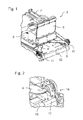
- Fig. 1 shows in a perspective view of an embodiment of the gripping device 3 of a gripping system 1, which is designed according to the inventive design principle.
- the gripping system 1 has a gripper arm 2, at the end of which the gripping device 3 is arranged.
- the gripper arm 2, which is designed in particular as a robot arm, allows the gripping device 3 and thus the vehicle seat gripped by the gripping device 3 to be moved three-dimensionally.
- the gripping device 3 has gripping elements 4, which are designed for the positive and non-positive engagement in at least two receiving elements 11 which are provided in the transition region 14 of the seat surface 12 to the back surface 13 of the vehicle seat.
- gripping elements 4 represent gripping pliers whose free ends 8 engage positively and non-positively in the receiving elements 11 on the vehicle seat.
- the receiving elements 11 are arranged laterally in the transition region 14, so that the gripping elements 4 designed as gripping tongs must be spread apart for engagement in the receiving elements 11.
- Fig. 1 shows the gripping elements 4 in the spread apart state, that is in the engaged state in the receiving elements 11 of the vehicle seat.
- the gripping elements 4 are positioned in the non-spread state in the transition region 14 between the seat surface 12 and the backrest surface of the vehicle seat. That is, the gripping elements 4 are positioned between the receiving elements 11, which are preferably arranged on the outer sides in the transition region 14 between the seat surface 12 and the backrest surface of the vehicle seat. When spreading or clamping of the gripping elements 4, the free ends 8 of the gripping elements engage in a form-fitting manner in the receiving elements 11 of the vehicle seat, which recesses are preferably recesses or recesses.
- the gripping elements 4 brace such that the vehicle seat firmly, that is non-positively and positively, is gripped by the gripping elements 4.
- the gripping device 3 further comprises a first movable abutment device 5, which is designed to rest against the backrest surface of the vehicle seat on. Furthermore, the gripping device 3 has a second movable abutment device 6, which is designed to rest against the seat surface 12 of the vehicle seat.
- the movable abutment devices 5, 6 of the gripping device 3 are preferably mechanically or pneumatically actuated. For pneumatic actuation of the movable abutment devices 5, 6, for example, a clamping cylinder 7 may be provided, as in Fig. 1 shown.
- the movable abutment devices 5, 6 are applied to the seat surface 12 and the backrest surface 13 of the vehicle seat, so that the seat after gripping by the gripping elements 4 relative to the gripping device 3 can not tilt.
- the tension of the seat 12 against the back surface 13 of the vehicle seat by the movable abutment means 5, 6 prevents the gripping elements 4 and the free ends 8 of the gripping elements 4 cancel due to the weight of the vehicle seat.
- FIG. 2 is a perspective view of a gripping element 4 of the gripping device 3 according to Fig. 1 shown.
- the gripping element 4 or the free end 8 of the gripping element 4 engages positively in the receiving element 11 of the vehicle seat.
- the gripping element 4 is designed as gripping tongs. By spreading apart at least two gripping elements 4 in opposite directions, these are clamped non-positively in the receiving elements 11 in the transition region 14 between the seat 12 and the backrest surface 13 of the vehicle seat. As a result, the vehicle seat can be gripped by the gripping device 3 and lifted by the gripper arm of the gripping system.
- Fig. 3 is the gripping device according to Fig. 1 in a side view, during the gripping of a vehicle seat, shown.
- Fig. 4 is the gripping device according to Fig. 1 in a plan view, during the gripping of a vehicle seat shown.
- the gripper elements 4 designed as gripping tongs are positioned between the receiving elements 11 of the vehicle seat 10. After the positioning of the gripping elements 4 they are braced, that is spread apart until they engage positively in the two arranged on the sides of the transition region 14 between the seat surface 12 and the back surface of the vehicle seat receiving elements 11.
- the first movable abutment device 5 can be pressed by means of the clamping cylinder 7 against the backrest surface 13 of the vehicle seat 10, the second movable abutment device 6 can be pressed against the seat surface 12 of the vehicle seat 10.
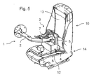
- the vehicle seat 10 can not be tilted to the gripping device 3 and fixed on the gripper arm 2 automated or manually easily and safely in a body of a vehicle, in particular a motor vehicle, are introduced. This is again in Fig. 5 shown.
- Fig. 5 shown.
- FIG. 5 shows in a perspective view of a gripping system 1, which is designed according to the inventive design principle.
- the vehicle seat 10 is gripped by the gripping device 3 of the gripping system 1.
- the gripper arm 2 allows the free movement of the vehicle seat 10. This can be rotated or pivoted by the gripper arm 2, so that it can be easily inserted into the body of a vehicle.
- a gripping system 1 with positive locking in the center of gravity of the seat structure of the vehicle seat 10 is shown.
- the gripping elements 4 of the gripping device 3 of the gripper system 1 which are preferably designed as gripper tongs or as a bolt, are positioned between the seat surface 12 and the back surface 13 by means of the gripper arm 2 and are then positively or pneumatically mechanically or mechanically in the geometry provided in the front seat, that is the receiving elements 11 braced.
- the first and second movable abutment means 5, 6 by means of the clamping cylinder 7 against the seat back or
Landscapes
- Engineering & Computer Science (AREA)
- Mechanical Engineering (AREA)
- Robotics (AREA)
- Transportation (AREA)
- Manufacturing & Machinery (AREA)
- Chemical & Material Sciences (AREA)
- Combustion & Propulsion (AREA)
- Aviation & Aerospace Engineering (AREA)
- Automobile Manufacture Line, Endless Track Vehicle, Trailer (AREA)
- Manipulator (AREA)
Applications Claiming Priority (1)
| Application Number | Priority Date | Filing Date | Title |
|---|---|---|---|
| DE102010013366A DE102010013366A1 (de) | 2010-03-30 | 2010-03-30 | Greifsystem und Verfahren zum Einbringen eines Fahrzeugsitzes in die Karosserie eines Fahrzeuges |
Publications (2)
| Publication Number | Publication Date |
|---|---|
| EP2371683A1 true EP2371683A1 (fr) | 2011-10-05 |
| EP2371683B1 EP2371683B1 (fr) | 2019-08-21 |
Family
ID=44170202
Family Applications (1)
| Application Number | Title | Priority Date | Filing Date |
|---|---|---|---|
| EP11154450.8A Active EP2371683B1 (fr) | 2010-03-30 | 2011-02-15 | Système de saisie et procédé d'introduction d'un siège de véhicule dans la carrosserie d'un véhicule |
Country Status (2)
| Country | Link |
|---|---|
| EP (1) | EP2371683B1 (fr) |
| DE (1) | DE102010013366A1 (fr) |
Cited By (1)
| Publication number | Priority date | Publication date | Assignee | Title |
|---|---|---|---|---|
| JP2017178280A (ja) * | 2016-03-31 | 2017-10-05 | テイ・エス テック株式会社 | シートフレーム組付ユニット及びシートフレーム製造方法 |
Families Citing this family (1)
| Publication number | Priority date | Publication date | Assignee | Title |
|---|---|---|---|---|
| DE102012222384A1 (de) * | 2012-12-06 | 2014-06-12 | Bayerische Motoren Werke Aktiengesellschaft | Greifer, Greifsystem sowie Einbauverfahren für Fahrzeugsitze |
Citations (5)
| Publication number | Priority date | Publication date | Assignee | Title |
|---|---|---|---|---|
| JPH0692278A (ja) * | 1992-09-11 | 1994-04-05 | Mazda Motor Corp | 車両シートの搭載装置 |
| JPH1149054A (ja) * | 1997-08-01 | 1999-02-23 | T K M Eng:Kk | 車両用シートの搭載装置及び同搭載方法並びにシート把持ハンド |
| DE10250680A1 (de) * | 2002-10-31 | 2004-05-19 | Adam Opel Ag | Greifvorrichtung für gepolsterte Sitze, insbesondere Kraftfahrzeugsitze |
| JP2005329895A (ja) * | 2004-05-21 | 2005-12-02 | Nissan Motor Co Ltd | 車両用シート搭載装置および搭載方法 |
| DE202008014157U1 (de) | 2007-10-29 | 2009-02-26 | Keiper Gmbh & Co.Kg | Fahrzeugsitz, insbesondere Kraftfahrzeugsitz |
Family Cites Families (2)
| Publication number | Priority date | Publication date | Assignee | Title |
|---|---|---|---|---|
| DE4413063A1 (de) * | 1993-04-15 | 1994-10-20 | Mazda Motor | Verfahren zum Einbringen von Sitzen in eine Kraftfahrzeugkarosserie und Robotergreifeinheit zum Einspannen des Sitzes |
| DE10351658B4 (de) * | 2003-11-05 | 2008-12-18 | Daimler Ag | Greifwerkzeug zur automatisierten Montage eines Sitzes |
-
2010
- 2010-03-30 DE DE102010013366A patent/DE102010013366A1/de not_active Withdrawn
-
2011
- 2011-02-15 EP EP11154450.8A patent/EP2371683B1/fr active Active
Patent Citations (5)
| Publication number | Priority date | Publication date | Assignee | Title |
|---|---|---|---|---|
| JPH0692278A (ja) * | 1992-09-11 | 1994-04-05 | Mazda Motor Corp | 車両シートの搭載装置 |
| JPH1149054A (ja) * | 1997-08-01 | 1999-02-23 | T K M Eng:Kk | 車両用シートの搭載装置及び同搭載方法並びにシート把持ハンド |
| DE10250680A1 (de) * | 2002-10-31 | 2004-05-19 | Adam Opel Ag | Greifvorrichtung für gepolsterte Sitze, insbesondere Kraftfahrzeugsitze |
| JP2005329895A (ja) * | 2004-05-21 | 2005-12-02 | Nissan Motor Co Ltd | 車両用シート搭載装置および搭載方法 |
| DE202008014157U1 (de) | 2007-10-29 | 2009-02-26 | Keiper Gmbh & Co.Kg | Fahrzeugsitz, insbesondere Kraftfahrzeugsitz |
Cited By (1)
| Publication number | Priority date | Publication date | Assignee | Title |
|---|---|---|---|---|
| JP2017178280A (ja) * | 2016-03-31 | 2017-10-05 | テイ・エス テック株式会社 | シートフレーム組付ユニット及びシートフレーム製造方法 |
Also Published As
| Publication number | Publication date |
|---|---|
| DE102010013366A1 (de) | 2011-10-06 |
| EP2371683B1 (fr) | 2019-08-21 |
Similar Documents
| Publication | Publication Date | Title |
|---|---|---|
| DE69901443T2 (de) | Herstellungsverfahren einer autokarosserie | |
| EP3472403B1 (fr) | Dispositif servant à fixer un élément en forme de plaque dans une rainure de réception d'un rail de support | |
| DE102011107210A1 (de) | Halteeinrichtung zur Halterung einer Baueinheit an einem Kraftwagen | |
| DE102015223057A1 (de) | Prüfadapter | |
| DE102015113689A1 (de) | Haltevorrichtung für eine Fahrzeug-Dachlast | |
| EP2371683B1 (fr) | Système de saisie et procédé d'introduction d'un siège de véhicule dans la carrosserie d'un véhicule | |
| DE102017212345A1 (de) | Bewegliche Stützstruktur für einen Fahrzeugsitz | |
| DE202014004601U1 (de) | Vorrichtung zur Befestigung von Fahrzeugsitzen | |
| DE102014009988A1 (de) | Vorrichtung zur Befestigung eines elektrischen Energiespeichers in einem Kraftfahrzeug | |
| DE102009048186B4 (de) | Vorrichtung zur Montage eines Lenkerelements sowie Verfahren zur Montage eines Lenkerelements | |
| DE102008011560B3 (de) | Verriegelungsvorrichtung, insbesondere für eine Kopfstütze für Fahrzeugsitze | |
| DE202005005689U1 (de) | Vorrichtung zur Festlegung eines ersten Fahrzeugteiles an einem zweiten Fahrzeugteil | |
| DE102017209502A1 (de) | Befestigungseinrichtung, Verfahren zur Herstellung einer Befestigungseinrichtung und Kraftfahrzeug | |
| DE102022117243A1 (de) | Schlosshalter für einen Kraftfahrzeug-Türverschluss | |
| DE102022110714A1 (de) | Befestigungsanordnung | |
| DE102007014727A1 (de) | Fahrzeugsitz, insbesondere Kraftfahrzeugsitz | |
| EP3592623B1 (fr) | Véhicule ferroviaire | |
| DE102004018552B3 (de) | Einrichtung zum Abkoppeln eines Fahrzeugbauteils von einem Karosserieteil | |
| DE102023116245A1 (de) | Schlosshalter für einen Kraftfahrzeug-Türverschluss | |
| DE102016201690B4 (de) | Adaptionselement, Anbausystem, Handhabungssystem, Kraftfahrzeug und Verfahren zur Montage eines Anbauteils an eine Tragstruktur | |
| DE102012222384A1 (de) | Greifer, Greifsystem sowie Einbauverfahren für Fahrzeugsitze | |
| DE202019100296U1 (de) | Spannvorrichtung, insbesondere zum Spannen von Werkstücken | |
| DE102011114863B4 (de) | Baugruppe für eine Anlage zum Einbau in einem Fahrzeug | |
| DE102011050572B4 (de) | Vorrichtung zum Umklappen einer Rückenlehne eines Fahrzeugsitzes | |
| DE102022117244A1 (de) | Schlosshalter für einen Kraftfahrzeugtürverschluss |
Legal Events
| Date | Code | Title | Description |
|---|---|---|---|
| PUAI | Public reference made under article 153(3) epc to a published international application that has entered the european phase |
Free format text: ORIGINAL CODE: 0009012 |
|
| AK | Designated contracting states |
Kind code of ref document: A1 Designated state(s): AL AT BE BG CH CY CZ DE DK EE ES FI FR GB GR HR HU IE IS IT LI LT LU LV MC MK MT NL NO PL PT RO RS SE SI SK SM TR |
|
| AX | Request for extension of the european patent |
Extension state: BA ME |
|
| 17P | Request for examination filed |
Effective date: 20111020 |
|
| RAP1 | Party data changed (applicant data changed or rights of an application transferred) |
Owner name: BAYERISCHE MOTOREN WERKE AKTIENGESELLSCHAFT |
|
| STAA | Information on the status of an ep patent application or granted ep patent |
Free format text: STATUS: EXAMINATION IS IN PROGRESS |
|
| 17Q | First examination report despatched |
Effective date: 20170915 |
|
| GRAP | Despatch of communication of intention to grant a patent |
Free format text: ORIGINAL CODE: EPIDOSNIGR1 |
|
| STAA | Information on the status of an ep patent application or granted ep patent |
Free format text: STATUS: GRANT OF PATENT IS INTENDED |
|
| INTG | Intention to grant announced |
Effective date: 20190308 |
|
| GRAJ | Information related to disapproval of communication of intention to grant by the applicant or resumption of examination proceedings by the epo deleted |
Free format text: ORIGINAL CODE: EPIDOSDIGR1 |
|
| GRAL | Information related to payment of fee for publishing/printing deleted |
Free format text: ORIGINAL CODE: EPIDOSDIGR3 |
|
| GRAS | Grant fee paid |
Free format text: ORIGINAL CODE: EPIDOSNIGR3 |
|
| STAA | Information on the status of an ep patent application or granted ep patent |
Free format text: STATUS: EXAMINATION IS IN PROGRESS |
|
| GRAR | Information related to intention to grant a patent recorded |
Free format text: ORIGINAL CODE: EPIDOSNIGR71 |
|
| STAA | Information on the status of an ep patent application or granted ep patent |
Free format text: STATUS: GRANT OF PATENT IS INTENDED |
|
| GRAA | (expected) grant |
Free format text: ORIGINAL CODE: 0009210 |
|
| STAA | Information on the status of an ep patent application or granted ep patent |
Free format text: STATUS: THE PATENT HAS BEEN GRANTED |
|
| INTC | Intention to grant announced (deleted) | ||
| AK | Designated contracting states |
Kind code of ref document: B1 Designated state(s): AL AT BE BG CH CY CZ DE DK EE ES FI FR GB GR HR HU IE IS IT LI LT LU LV MC MK MT NL NO PL PT RO RS SE SI SK SM TR |
|
| INTG | Intention to grant announced |
Effective date: 20190715 |
|
| REG | Reference to a national code |
Ref country code: GB Ref legal event code: FG4D Free format text: NOT ENGLISH |
|
| REG | Reference to a national code |
Ref country code: CH Ref legal event code: EP |
|
| REG | Reference to a national code |
Ref country code: DE Ref legal event code: R096 Ref document number: 502011016017 Country of ref document: DE |
|
| REG | Reference to a national code |
Ref country code: AT Ref legal event code: REF Ref document number: 1169426 Country of ref document: AT Kind code of ref document: T Effective date: 20190915 |
|
| REG | Reference to a national code |
Ref country code: IE Ref legal event code: FG4D Free format text: LANGUAGE OF EP DOCUMENT: GERMAN |
|
| REG | Reference to a national code |
Ref country code: LT Ref legal event code: MG4D |
|
| REG | Reference to a national code |
Ref country code: NL Ref legal event code: MP Effective date: 20190821 |
|
| PG25 | Lapsed in a contracting state [announced via postgrant information from national office to epo] |
Ref country code: HR Free format text: LAPSE BECAUSE OF FAILURE TO SUBMIT A TRANSLATION OF THE DESCRIPTION OR TO PAY THE FEE WITHIN THE PRESCRIBED TIME-LIMIT Effective date: 20190821 Ref country code: NL Free format text: LAPSE BECAUSE OF FAILURE TO SUBMIT A TRANSLATION OF THE DESCRIPTION OR TO PAY THE FEE WITHIN THE PRESCRIBED TIME-LIMIT Effective date: 20190821 Ref country code: BG Free format text: LAPSE BECAUSE OF FAILURE TO SUBMIT A TRANSLATION OF THE DESCRIPTION OR TO PAY THE FEE WITHIN THE PRESCRIBED TIME-LIMIT Effective date: 20191121 Ref country code: NO Free format text: LAPSE BECAUSE OF FAILURE TO SUBMIT A TRANSLATION OF THE DESCRIPTION OR TO PAY THE FEE WITHIN THE PRESCRIBED TIME-LIMIT Effective date: 20191121 Ref country code: LT Free format text: LAPSE BECAUSE OF FAILURE TO SUBMIT A TRANSLATION OF THE DESCRIPTION OR TO PAY THE FEE WITHIN THE PRESCRIBED TIME-LIMIT Effective date: 20190821 Ref country code: FI Free format text: LAPSE BECAUSE OF FAILURE TO SUBMIT A TRANSLATION OF THE DESCRIPTION OR TO PAY THE FEE WITHIN THE PRESCRIBED TIME-LIMIT Effective date: 20190821 Ref country code: PT Free format text: LAPSE BECAUSE OF FAILURE TO SUBMIT A TRANSLATION OF THE DESCRIPTION OR TO PAY THE FEE WITHIN THE PRESCRIBED TIME-LIMIT Effective date: 20191223 Ref country code: SE Free format text: LAPSE BECAUSE OF FAILURE TO SUBMIT A TRANSLATION OF THE DESCRIPTION OR TO PAY THE FEE WITHIN THE PRESCRIBED TIME-LIMIT Effective date: 20190821 |
|
| PG25 | Lapsed in a contracting state [announced via postgrant information from national office to epo] |
Ref country code: LV Free format text: LAPSE BECAUSE OF FAILURE TO SUBMIT A TRANSLATION OF THE DESCRIPTION OR TO PAY THE FEE WITHIN THE PRESCRIBED TIME-LIMIT Effective date: 20190821 Ref country code: AL Free format text: LAPSE BECAUSE OF FAILURE TO SUBMIT A TRANSLATION OF THE DESCRIPTION OR TO PAY THE FEE WITHIN THE PRESCRIBED TIME-LIMIT Effective date: 20190821 Ref country code: GR Free format text: LAPSE BECAUSE OF FAILURE TO SUBMIT A TRANSLATION OF THE DESCRIPTION OR TO PAY THE FEE WITHIN THE PRESCRIBED TIME-LIMIT Effective date: 20191122 Ref country code: IS Free format text: LAPSE BECAUSE OF FAILURE TO SUBMIT A TRANSLATION OF THE DESCRIPTION OR TO PAY THE FEE WITHIN THE PRESCRIBED TIME-LIMIT Effective date: 20191221 Ref country code: RS Free format text: LAPSE BECAUSE OF FAILURE TO SUBMIT A TRANSLATION OF THE DESCRIPTION OR TO PAY THE FEE WITHIN THE PRESCRIBED TIME-LIMIT Effective date: 20190821 Ref country code: ES Free format text: LAPSE BECAUSE OF FAILURE TO SUBMIT A TRANSLATION OF THE DESCRIPTION OR TO PAY THE FEE WITHIN THE PRESCRIBED TIME-LIMIT Effective date: 20190821 |
|
| PG25 | Lapsed in a contracting state [announced via postgrant information from national office to epo] |
Ref country code: TR Free format text: LAPSE BECAUSE OF FAILURE TO SUBMIT A TRANSLATION OF THE DESCRIPTION OR TO PAY THE FEE WITHIN THE PRESCRIBED TIME-LIMIT Effective date: 20190821 |
|
| PG25 | Lapsed in a contracting state [announced via postgrant information from national office to epo] |
Ref country code: EE Free format text: LAPSE BECAUSE OF FAILURE TO SUBMIT A TRANSLATION OF THE DESCRIPTION OR TO PAY THE FEE WITHIN THE PRESCRIBED TIME-LIMIT Effective date: 20190821 Ref country code: DK Free format text: LAPSE BECAUSE OF FAILURE TO SUBMIT A TRANSLATION OF THE DESCRIPTION OR TO PAY THE FEE WITHIN THE PRESCRIBED TIME-LIMIT Effective date: 20190821 Ref country code: RO Free format text: LAPSE BECAUSE OF FAILURE TO SUBMIT A TRANSLATION OF THE DESCRIPTION OR TO PAY THE FEE WITHIN THE PRESCRIBED TIME-LIMIT Effective date: 20190821 Ref country code: IT Free format text: LAPSE BECAUSE OF FAILURE TO SUBMIT A TRANSLATION OF THE DESCRIPTION OR TO PAY THE FEE WITHIN THE PRESCRIBED TIME-LIMIT Effective date: 20190821 Ref country code: PL Free format text: LAPSE BECAUSE OF FAILURE TO SUBMIT A TRANSLATION OF THE DESCRIPTION OR TO PAY THE FEE WITHIN THE PRESCRIBED TIME-LIMIT Effective date: 20190821 |
|
| PG25 | Lapsed in a contracting state [announced via postgrant information from national office to epo] |
Ref country code: IS Free format text: LAPSE BECAUSE OF FAILURE TO SUBMIT A TRANSLATION OF THE DESCRIPTION OR TO PAY THE FEE WITHIN THE PRESCRIBED TIME-LIMIT Effective date: 20200224 Ref country code: CZ Free format text: LAPSE BECAUSE OF FAILURE TO SUBMIT A TRANSLATION OF THE DESCRIPTION OR TO PAY THE FEE WITHIN THE PRESCRIBED TIME-LIMIT Effective date: 20190821 Ref country code: SK Free format text: LAPSE BECAUSE OF FAILURE TO SUBMIT A TRANSLATION OF THE DESCRIPTION OR TO PAY THE FEE WITHIN THE PRESCRIBED TIME-LIMIT Effective date: 20190821 Ref country code: SM Free format text: LAPSE BECAUSE OF FAILURE TO SUBMIT A TRANSLATION OF THE DESCRIPTION OR TO PAY THE FEE WITHIN THE PRESCRIBED TIME-LIMIT Effective date: 20190821 |
|
| REG | Reference to a national code |
Ref country code: DE Ref legal event code: R097 Ref document number: 502011016017 Country of ref document: DE |
|
| PLBE | No opposition filed within time limit |
Free format text: ORIGINAL CODE: 0009261 |
|
| STAA | Information on the status of an ep patent application or granted ep patent |
Free format text: STATUS: NO OPPOSITION FILED WITHIN TIME LIMIT |
|
| PG2D | Information on lapse in contracting state deleted |
Ref country code: IS |
|
| 26N | No opposition filed |
Effective date: 20200603 |
|
| PG25 | Lapsed in a contracting state [announced via postgrant information from national office to epo] |
Ref country code: SI Free format text: LAPSE BECAUSE OF FAILURE TO SUBMIT A TRANSLATION OF THE DESCRIPTION OR TO PAY THE FEE WITHIN THE PRESCRIBED TIME-LIMIT Effective date: 20190821 |
|
| REG | Reference to a national code |
Ref country code: CH Ref legal event code: PL |
|
| REG | Reference to a national code |
Ref country code: BE Ref legal event code: MM Effective date: 20200229 |
|
| PG25 | Lapsed in a contracting state [announced via postgrant information from national office to epo] |
Ref country code: MC Free format text: LAPSE BECAUSE OF FAILURE TO SUBMIT A TRANSLATION OF THE DESCRIPTION OR TO PAY THE FEE WITHIN THE PRESCRIBED TIME-LIMIT Effective date: 20190821 Ref country code: LU Free format text: LAPSE BECAUSE OF NON-PAYMENT OF DUE FEES Effective date: 20200215 |
|
| PG25 | Lapsed in a contracting state [announced via postgrant information from national office to epo] |
Ref country code: CH Free format text: LAPSE BECAUSE OF NON-PAYMENT OF DUE FEES Effective date: 20200229 Ref country code: LI Free format text: LAPSE BECAUSE OF NON-PAYMENT OF DUE FEES Effective date: 20200229 |
|
| PG25 | Lapsed in a contracting state [announced via postgrant information from national office to epo] |
Ref country code: IE Free format text: LAPSE BECAUSE OF NON-PAYMENT OF DUE FEES Effective date: 20200215 |
|
| PG25 | Lapsed in a contracting state [announced via postgrant information from national office to epo] |
Ref country code: BE Free format text: LAPSE BECAUSE OF NON-PAYMENT OF DUE FEES Effective date: 20200229 |
|
| REG | Reference to a national code |
Ref country code: AT Ref legal event code: MM01 Ref document number: 1169426 Country of ref document: AT Kind code of ref document: T Effective date: 20200215 |
|
| PG25 | Lapsed in a contracting state [announced via postgrant information from national office to epo] |
Ref country code: AT Free format text: LAPSE BECAUSE OF NON-PAYMENT OF DUE FEES Effective date: 20200215 |
|
| PG25 | Lapsed in a contracting state [announced via postgrant information from national office to epo] |
Ref country code: MT Free format text: LAPSE BECAUSE OF FAILURE TO SUBMIT A TRANSLATION OF THE DESCRIPTION OR TO PAY THE FEE WITHIN THE PRESCRIBED TIME-LIMIT Effective date: 20190821 Ref country code: CY Free format text: LAPSE BECAUSE OF FAILURE TO SUBMIT A TRANSLATION OF THE DESCRIPTION OR TO PAY THE FEE WITHIN THE PRESCRIBED TIME-LIMIT Effective date: 20190821 |
|
| PG25 | Lapsed in a contracting state [announced via postgrant information from national office to epo] |
Ref country code: MK Free format text: LAPSE BECAUSE OF FAILURE TO SUBMIT A TRANSLATION OF THE DESCRIPTION OR TO PAY THE FEE WITHIN THE PRESCRIBED TIME-LIMIT Effective date: 20190821 |
|
| P01 | Opt-out of the competence of the unified patent court (upc) registered |
Effective date: 20230502 |
|
| PGFP | Annual fee paid to national office [announced via postgrant information from national office to epo] |
Ref country code: GB Payment date: 20260219 Year of fee payment: 16 |
|
| PGFP | Annual fee paid to national office [announced via postgrant information from national office to epo] |
Ref country code: DE Payment date: 20260210 Year of fee payment: 16 |
|
| PGFP | Annual fee paid to national office [announced via postgrant information from national office to epo] |
Ref country code: FR Payment date: 20260223 Year of fee payment: 16 |